1
AGRI-ALERT 9600
ALARM SYSTEM
INSTALLATION MANUAL
R12
Manufacturer:
Viatron Electronics
3514 1st Street,
St-Hubert (Quebec)
Canada
J3Y 8Y5
WARNING: the warranty can be void if the Agri-Alert 9600 is used in a manner not
specified by the manufacturer.
2
AA-9600.rev.12
TABLE OF CONTENTS
SYSTEM OVERVIEW .......................................................................................... 8
CHAPTER ONE: INSTALLATION ....................................................................... 10
1.1 INSTALLATION PROCEDURE ............................................................................. 10
1.2 CONFIGURING THE SYSTEM ............................................................................ 11
1.2.1 Main Board ................................................................................................... 11
1.2.2 Extension Cards ............................................................................................ 13
1.3 MOUNTING THE EQUIPMENT ........................................................................... 16
1.4 CONNECTING THE EQUIPMENT ........................................................................ 17
1.4.1 Sensors ........................................................................................................ 18
1.4.2 Supply Inputs ............................................................................................... 18
1.4.2.1 Backup Battery Connection ................................................................... 18
1.4.2.2 AC Power Connection .......................................................................... 18
1.4.3 Terminal Outputs .......................................................................................... 19
1.4.3.1 0-10V Output ...................................................................................... 19
1.4.3.2 Siren Output ....................................................................................... 19
1.4.3.3 12VDC Output..................................................................................... 19
1.4.4 External Microphone / Microphone Box Hookup .............................................. 19
1.4.5 Phone Hookup .............................................................................................. 21
1.4.6 Programmable Outputs .................................................................................. 22
1.4.7 Connecting the Earth Ground ......................................................................... 23
1.5 SERIAL BUS INTERFACE CONNECTIONS ............................................................ 24
1.5.1 Connecting Devices to the AA-9600 ............................................................... 24
1.5.2 End of Line Jumpers ...................................................................................... 24
1.5.3 Connecting a Bridge-A to the AA-9600 ........................................................... 25
CHAPTER TWO: USER INTERFACE ................................................................... 26
2.1 FRONT PANEL ................................................................................................. 26
2.2 MEANING OF STATUS LEDS ............................................................................ 27
2.3 DISPLAYING A PARAMETER ............................................................................. 27
2.4 MODIFYING A PARAMETER .............................................................................. 28
2.5 HOW TO USE THE MENUS ............................................................................... 29
CHAPTER THREE: SYSTEM INITIALIZATION ...................................................... 31
3.1 SYSTEM INSTALLATION MENUS....................................................................... 31
3.2 EXTENSION CARD INITIALIZATION .................................................................... 32
3.3 DEVICE INITIALIZATION ................................................................................... 34
3.3.1 Add Device to Network ................................................................................. 34
3.3.2 Remove Device from Network ........................................................................ 36
3.3.3 Edit Device Label .......................................................................................... 37
3.3.4 Upload Data To/From a UP-1000 ..................................................................... 39
3.3.5 Upload Data to a Device ................................................................................. 40
3.3.7 Display Device Information ............................................................................ 42
3.4 ZONE ASSIGNMENTS ...................................................................................... 43
3.4.1 Manual Assignment ....................................................................................... 45
3.4.2 Automatic Assignments ................................................................................. 45
AA-9600.rev.12
3
3.4.3 Assigning an External Zone ........................................................................... 47
3.5 SBI INITIALIZATION ......................................................................................... 50
3.5.1 Disable SBI in Case of Low Battery ................................................................. 50
3.5.2 Adjust SBI Speed .......................................................................................... 51
3.5.3 Monitor SBI .................................................................................................. 52
3.6 SYSTEM CLOCK ............................................................................................. 53
3.7 TEMPERATURE UNITS ..................................................................................... 54
3.8 DISPLAY CONTRAST ....................................................................................... 55
3.9 USER ID MESSAGE ......................................................................................... 56
3.10 DELETING ALL ID MESSAGES ......................................................................... 58
3.11 DEFAULT VALUES ......................................................................................... 59
3.12 MONITOR 12VDC OUTPUT ............................................................................. 63
3.13 TEST PROCEDURE ......................................................................................... 64
3.14 VIEWING SOFTWARE VERSION ....................................................................... 65
CHAPTER FOUR: ZONE CONFIGURATION ......................................................... 66
4.1 CONFIGURATION ............................................................................................ 67
4.1.1 Dry Contact Input ......................................................................................... 68
4.1.2 Dry Contact Burglar Input .............................................................................. 73
4.1.3 Temperature Input ......................................................................................... 77
4.1.3.1 Calibration of the Temperature Probes .................................................... 78
4.1.3.2 Configuration of a Temperature Zone ..................................................... 79
4.1.4 4-20mA Input ............................................................................................... 83
4.1.5 AC Current Sensor Input ............................................................................... 86
4.1.6 0-5V Input ................................................................................................... 89
4.1.7 Disable the Siren ........................................................................................... 91
4.2 COPYING A ZONE CONFIGURATION TO ANOTHER ZONE ..................................... 92
4.3 DISPLAY ZONE INFORMATION .......................................................................... 93
4.4 EDIT ZONE LABEL ........................................................................................... 94
4.5 ZONE ID MESSAGE ......................................................................................... 95
4.6 RESET TIME ................................................................................................... 97
4.7 MIN/MAX TIME ............................................................................................... 99
4.8 DELETING THE ZONES ................................................................................... 100
4.8.1 Deleting Individual Zones .............................................................................. 100
4.8.2 Deleting Devices’ Zones ................................................................................ 101
4.8.3 Deleting All Zones ....................................................................................... 102
CHAPTER FIVE: COMMUNICATION PARAMETERS ............................................ 103
5.1 CENTRAL ALARM REPORTING CODES ............................................................. 103
5.1.1 Setting the Account Number ....................................................................... 104
5.1.2 Setting Alarm Codes for Zones ................................................................... 105
5.1.3 Setting Alarm Codes for System Alarms ....................................................... 106
5.1.4 Setting Restore Codes for Zones .................................................................. 108
5.1.5 Setting Restore Codes for System Alarms ..................................................... 110
5.1.6 Reporting Temperature Readings to Central Alarm Facility .............................. 111
5.1.7 Reporting Zone and Partition Status Changes ............................................... 113
5.1.8 Reporting Speed to the Central Alarm Facility ............................................... 114
5.2 DIALING INFORMATION ................................................................................. 116
5.2.1 Dialing Mode and Speed .............................................................................. 117
4
AA-9600.rev.12
5.2.1.1 Dialing Mode ..................................................................................... 118
5.2.1.2 Tone Dialing Speed ............................................................................ 119
5.2.1.3 Pulse Dialing Speed ............................................................................ 120
5.2.2 Line Seizure ................................................................................................ 122
5.2.3 # of Call Repetitions .................................................................................... 123
5.2.4 Message Repetitions .................................................................................... 124
5.2.5 Busy Tries ................................................................................................... 125
5.2.6 Tone Delay ................................................................................................. 126
5.2.7 Pause Delay Key .......................................................................................... 127
5.2.8 Call Start Delay ........................................................................................... 128
5.2.9 Time Between Calls ..................................................................................... 129
5.2.10 Alarm Recall Time ...................................................................................... 130
5.2.11 Restore Calls ............................................................................................. 131
5.2.12 Disable the Dialer ...................................................................................... 132
5.3 PHONE NUMBERS ......................................................................................... 133
5.3.1 Home ......................................................................................................... 134
5.3.2 Cellular ....................................................................................................... 134
5.3.3 Beeper ........................................................................................................ 135
5.3.4 Pager .......................................................................................................... 135
5.3.5 Alarm Report .............................................................................................. 138
5.3.6 Test Report ................................................................................................. 138
5.4 ON SITE LISTENING ....................................................................................... 140
5.5 RINGS / ANSWERING MACHINE ...................................................................... 142
5.6 SYSTEM’S VOICE MUTE ................................................................................ 143
5.7 PHONE LINE CUT MONITORING ...................................................................... 144
CHAPTER SIX: SPECIAL FUNCTIONS .............................................................. 146
6.1 TROUBLE INFORMATION ................................................................................. 146
6.2 STANDBY MODE ........................................................................................... 147
6.3 EVENT BUFFER ............................................................................................. 148
6.4 PROGRAMMABLE OUTPUTS ........................................................................... 150
6.4.1
6.4.2
6.4.3
6.4.4
6.4.5
Switched Outputs on the Agri-Alert 9600 ..................................................... 150
0-10V Output on the Agri-Alert 9600 ........................................................... 152
Switched Outputs on Other Devices ............................................................. 152
Assigning a Programmable Output to a Zone ................................................. 154
Removing a Zone Assignment ...................................................................... 156
CHAPTER SEVEN: ALARM PARAMETERS ........................................................ 157
7.1 ALARM VALIDATION: SUMMARY OF EVENTS ................................................. 157
7.2 SYSTEM ALARMS ......................................................................................... 158
7.2.1 System Temperature Readout ....................................................................... 158
7.2.2 Backup Battery Voltage Readout .................................................................. 159
7.3 OUTDOOR TEMPERATURE COMPENSATION ON TEMPERATURE ALARMS ........... 160
7.3.1 To Make an Outdoor Probe Assignment ........................................................ 162
7.3.2 To Activate / Deactivate the Outdoor Temperature Compensation .................. 163
7.3.3 To Set the Offset Temperature ..................................................................... 164
7.4 ALARM MEMORY .......................................................................................... 165
7.5 ZONE STATUS DISPLAY ................................................................................. 166
7.5.1 Adjusting Set Points .................................................................................... 168
AA-9600.rev.12
5
7.5.2 Adjusting Curve Offset Values ..................................................................... 169
7.5.3 Adjusting Curve Points ................................................................................. 170
7.5.4 Enabling / Disabling Temperature Curve ........................................................ 171
7.5.5 Adjusting the Recognition Time ................................................................... 172
7.5.6 Copying Zone Set Points to Another Zone .................................................... 172
7.5.7 Resetting Minimum / Maximum Values .......................................................... 173
7.6 PARTITIONS ................................................................................................. 174
7.6.1 Adding a zone ............................................................................................. 175
7.6.2 Deleting a zone ........................................................................................... 175
7.6.3 Deleting a partition ..................................................................................... 176
7.7 BYPASS / ACTIVATE FUNCTION ..................................................................... 177
7.7.1 Changing Zone Status ................................................................................. 177
7.7.2 Changing Partition Status ............................................................................ 178
7.7.3 Viewing Bypassed Zones ............................................................................... 178
7.8 ENTRY DELAY .............................................................................................. 179
7.9 EXIT DELAY .................................................................................................. 180
7.10 FORCE ARMING .......................................................................................... 181
7.11 SIREN PARAMETERS ................................................................................... 182
7.11.1 Siren Delay ............................................................................................... 182
7.11.2 Siren Time On ........................................................................................... 183
7.11.3 Siren Monitoring ....................................................................................... 184
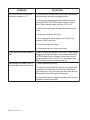
TROUBLESHOOTING GUIDE ........................................................................... 185
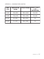
APPENDIX A: MAXIMUM WIRE LENGTHS ....................................................... 187
APPENDIX B: BACKUP BATTERY LIFE SPAN ................................................... 188
APPENDIX C: COMMUNICATION CABLE GAUGE AND MAXIMUM
LENGTH RECOMMENDATIONS ....................................................................... 189
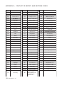
APPENDIX D: CONTACT ID REPORT AND RESTORE CODES .............................. 194
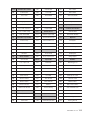
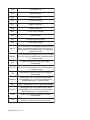
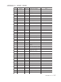
APPENDIX E: EVENT CODES ......................................................................... 197
APPENDIX F: SYSTEM KEY MENUS ................................................................ 204
GLOSSARY OF TERMS .................................................................................. 205
WIRING DIAGRAMS ...................................................................................... 207
TECHNICAL SPECIFICATIONS ......................................................................... 209
AA-9600 INSTALLATION GUIDE .................................................................... 210
REGISTRATION CARD ................................................................................... 213
6
AA-9600.rev.12
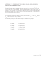
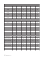
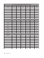
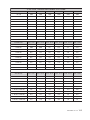
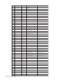
LIST OF TABLES AND FIGURES
Figure
Figure
Figure
Figure
Figure
Figure
Figure
Figure
Figure
Figure
Figure
Figure
Figure
Figure
Figure
Figure
Figure
Figure
Figure
Figure
Figure
Figure
Figure
Figure
Figure
Figure
Figure
Figure
Figure
Figure
Figure
Figure
Figure
Figure
Figure
Figure
Figure
Figure
Figure
Figure
1: AA9600 Installation Layout ............................................................................8
2: Location of the Main Board and Extension Cards ........................................... 11
3: Location of Jumpers on Main Board ............................................................. 12
4: Jumper Positions on Main Board .................................................................. 12
5: Extension Card Configuration ...................................................................... 13
6: Location of Connectors for Extension Cards.................................................. 15
7: Fastening the Extension Card Onto the Main Board ....................................... 15
8: Mounting the Enclosures ............................................................................. 16
9: Location of Mounting Holes......................................................................... 17
10: Electrical Knockouts for Battery and Transformer Hookup ............................. 17
11: Location of Microphone Jumper on Main Board ........................................... 20
12: Phone Hookup with Line Seizure ................................................................ 21
13: Phone Hookup without Line Seizure ........................................................... 22
14: Relay Output Connections (Agri-Alert, Relay Box) ........................................ 22
15: Location of the End of Line Jumper and the Communication Terminals ......... 24
16: Example of End of Line Jumper Positions .................................................... 25
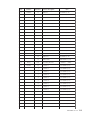
17: Example of a Zone Assignment .................................................................. 44
18: Example of Bridge-A Connection ................................................................ 47
19: Illustration of Recognition Time .................................................................. 67
20: Normally Open Circuits With EOLR ............................................................. 68
21: Normally Open Circuits with DEOLR ........................................................... 68
23: Examples of Zone Connections with EOLR .................................................. 69
22: Examples of Zone Connections Without EOLR ............................................. 69
24: Examples of Zone Connections with DEOLR ................................................ 70
25: Typical Application of Burglar Zones ........................................................... 73
26: Temperature Input ..................................................................................... 77
27: Temperature Input with Temperature Curve ................................................. 77
28: 4-20mA Input ........................................................................................... 83
29: Typical Connection for 4-20mA Input ......................................................... 83
30: AC Current Sensor Input ............................................................................ 86
31: Current Sensors’ Windings ......................................................................... 86
32: 0-5V Input ................................................................................................ 89
33: Illustration of Reset Time ........................................................................... 97
34: Pulse Timing Parameters .......................................................................... 117
35: Waiting Time .......................................................................................... 126
36: Calling a Pager Number ........................................................................... 137
37: Outdoor Temperature Compensation ......................................................... 160
38: Critical Temperature Monitoring ............................................................... 161
39: Monitoring the Indoor-Outdoor Temperature Difference ............................. 161
40: Example of Partitioning ........................................................................... 174
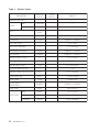
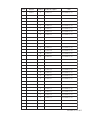
Table 1: Default Values ............................................................................................. 60
Table 2: Pager Codes Used by the Agri-Alert System ................................................. 136
Table 3: System Alarms ........................................................................................... 158
NOTICE
Every effort has been made to ensure that this manual is complete, accurate and up-to-date. The information contained in it
is however subject to change without notice due to further developments.
AA-9600.rev.12
7
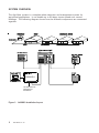
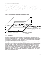
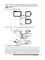
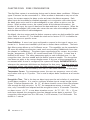
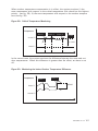
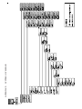
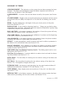
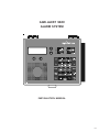
SYSTEM OVERVIEW
The Agri-Alert system is a complete alarm detection and management system for
agricultural applications. It can handle up to 96 alarm inputs spread over several
buildings. The following diagram shows how the different components are connected
together.
BRIDGE-A
TO TEMPERATURE
CONTROLLER
NETWORKS
Figure 1: AA9600 Installation Layout
8
AA-9600.rev.12
DEVICE DESCRIPTIONS
The complete system can include up to 98 devices.
AA-9600: the main system with 8 basic zones, two relays and one microphone. Two
extension cards can be added allowing 16 additional zones.
TP-800: a remote extension device that adds 8 zones and a programmable output to
the main system.
KP-400: a keypad for displaying system data from a remote location. Includes 4 dry
contact, burglar or temperature zones and one programmable output.
KPB-400: a dust- and moisture-tight keypad for displaying system data from a remote
location. Includes 4 dry contact, burglar or temperature zones and one programmable
output.
RB-800: a device containing 8 relays that the user can program as a function of zone
status.
LB-9600: a device containing 96 LEDs for indicating zone status.
BRIDGE: a computer communication device. Allows the user to operate the complete
system from a computer keyboard or modem. Datalogs up to 4 Agri-Alert systems (4
X 96 zones). When used with a Combridge-1 card, the Bridge is compatible with
AgBus, allowing the Agri-Alert to fetch temperature readings from existing controller
networks (see section 3.4.3).
KEYS TO SYMBOLS IN THE MANUAL
!
WARNING
Caution. Carefully read the following text for it contains important information which, if ignored, may cause the controller to operate improperly.
Pay attention. The following text contains very useful information.
AA-9600.rev.12
9
CHAPTER ONE: INSTALLATION
1.1 INSTALLATION PROCEDURE
What You Need:
!
WARNING
- Agri-Alert system including independent battery enclosure
- 12VDC 7Ah sealed lead acid battery
- a 16VAC/150VA transformer in a separate box
TO AVOID ELECTRICAL SHOCKS AND EQUIPMENT DAMAGE,
TURN OFF THE BREAKER ON WHICH IS CONNECTED THE UNIT
BEFORE CONFIGURING THE MAIN BOARD OR MAKING CONNECTIONS TO THE TERMINALS.
Step 1: Determine where you want to install the system. You need an
unswitched AC power outlet and a telephone plug nearby to operate the system.
Step 2: Make a list of all the sensor inputs you will be using with the Agri-Alert
system.
Step 3: Mount the Agri-Alert system and the battery enclosure on the wall (see
Section 1.3).
Step 4: Configure the main board in the Agri-Alert enclosure according to your
list of sensor inputs (see Section 1.2.1).
Step 5: If you have purchased one or two extension cards with the system,
configure them according to the remainder of the sensor inputs (see Section
1.2.2).
Step 6: Connect a ground wire (see Section 1.4.8).
Step 7: Hook up the sensors assigned to the extension cards to the terminals
provided (see Section 1.2.2).
Step 8: Plug the extension cards into the main board (see Section 1.2.2).
Step 9: Hook up the sensors, the telephone line, the microphone (if needed) and
the siren (if used) to the terminals on the main board in the Agri-Alert enclosure
(see Section 1.4).
Step 10: Hook up the battery (see 1.4.2.1) and plug the transformer into an AC
power outlet.
10
AA-9600.rev.12
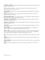
1.2 CONFIGURING THE SYSTEM
Before mounting the Agri-Alert system and making the connections, the system must
be configured to respond to the sensors you will be connecting to it. The main board
is the electronic card located inside the Agri-Alert enclosure. It can handle up to 8
sensor inputs. These inputs are called zones. Each extension card you add to the
main board provides 8 additional zones. Two extension cards can be added for a total
of 24 zones.
Figure 2: Location of the Main Board and Extension Cards
=21(6
(;7(16,21&$5'
=21(6
0$,1%2$5'
=21(6
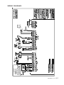
1.2.1 Main Board
Before you configure the zones, you need to determine which sensors you will be
connecting to each board and in what order. Zones are then configured using jumpers.
The diagram on the next page shows the location of the jumpers on the main board.
To configure the extension cards, see Section 1.2.2.
To configure a zone, place the corresponding jumper in the correct position for the
sensor being used. There are three jumper positions for each zone. The first position,
called DRY/TEMP, is for dry contact (normally closed with or without EOLR/DEOLR;
normally open with or without EOLR/DEOLR) and temperature inputs. The second
position is for 4-20MA inputs and the third is for 0-5VOLT and AC current sensor
inputs. Only one jumper is used to configure each zone. Initially, all zones are configured for DRY/TEMP. The zone numbers are printed on the main board. Use caution
when prying the jumpers loose.
AA-9600.rev.12
11
Figure 3: Location of Jumpers on Main Board
ZONE JUMPERS
For example, to configure Zone 6 as a 4-20mA input, place the black jumper as
shown below:
Example :
Zone 6 is configured as 4-20 mA.
Figure 4: Jumper Positions on Main Board
12
AA-9600.rev.12
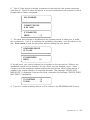
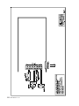
1.2.2 Extension Cards
The basic Agri-Alert system handles up to 8 different zones or sensor inputs. Up to
two extension cards can be added, each one providing 8 additional zones. Each extension card plugs into the main board located in the Agri-Alert enclosure. The figure
on the following page shows the configuration of an extension card.
ZONE
STICKER
EXTENSION
CARD
ZONE
JUMPERS
CONNECTOR
TO THE MAIN
BOARD
INPUT
TERMINALS
CONNECTOR
STICKER
Figure 5: Extension Card Configuration
STEP 1: Identifying the Cards — Before you plug the extension cards into the main
board, you need to configure the zones to correspond to the sensors you will be hooking up to each card. To do this, you must first identify the extension cards. Use the
stickers provided for assigning the cards. Each extension card needs a sticker to
identify the input terminals (Connector Sticker) and a sticker to identify the zones
(Zone Sticker). The location of these stickers is shown on the diagram above. Use the
zone number stickers to identify each individual zone.
STEP 2: Configuring the Zone Jumpers — Each zone is configured by placing a jumper
in the position corresponding to the sensor being used. This must be done before the
extension cards are plugged into the main board. There are three jumper positions for
each zone. The first position, called DRY/TEMP, is for dry contact (normally closed
with or without EOLR/DEOLR; normally open with or without EOLR/DEOLR) and temperature inputs. The second position is for 4-20MA inputs and the third is for 0-5VOLT
AA-9600.rev.12
13
and AC current sensor inputs. Only one jumper must be used for each zone. Initially,
all zones are configured for DRY/TEMP. The zone numbers are printed on the sticker.
STEP 3: Hooking up the Sensor Inputs — Before connecting the extension cards into
the main board, hook up the sensor inputs to the input terminals according to the
jumper configurations defined above.
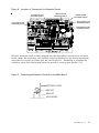
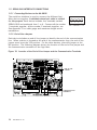
STEP 4: Connecting the Extension Cards — Once the extension cards have been
identified and configured as described above, they can be connected to the main
board. The diagram below shows the location of the connectors on the main board
used for the extension cards.
EXTENSION
CARD #1
Z9
Z10 Z11 Z12 Z13 Z14 Z15 Z16
Z9 GND Z10 Z11 GND Z12 Z13 GND Z14 Z15
14
AA-9600.rev.12
EXTENSION
CARD #2
Z17 Z18 Z19 Z20 Z21 Z22 Z23 Z24
Z16
Z17 GND Z18 Z19 GND Z20 Z21 GND Z22 Z23 GND Z24
Figure 6: Location of Connectors for Extension Cards
CONNECTOR FOR
EXTENSION CARD #1
LEFT BRACKET FOR
EXTENSION CARD #1
CONNECTOR FOR
EXTENSION CARD #2
RIGHT BRACKET FOR
EXTENSION CARD #1
LEFT BRACKET FOR
EXTENSION CARD #2
RIGHT BRACKET FOR
EXTENSION CARD #2
Once an extension card is firmly plugged into the appropriate connector on the main
board, fasten the extension card securely onto the brackets on the board (see above)
using the two screws provided with the card (Figure 6). Remember to initialize the
extension cards from the keypad once the system is running (see Section 2.2).
Figure 7: Fastening the Extension Card Onto the Main Board
(;7(16,21&$5'
%5$&.(7
%5$&.(7
0$,1%2$5'
AA-9600.rev.12
15
1.3 MOUNTING THE EQUIPMENT
The Agri-Alert system should be mounted on a wall as shown in the figure below. The
Agri-Alert enclosures are opened by pulling the latch on the bottom. The battery
enclosure is opened by pulling on the latch. Use 3/16” diameter screws to mount
each enclosure on the wall. Fasten the black caps onto the mounting holes once the
screws are tightened. Make sure the covers of the two boxes can be opened easily.
The battery enclosure has ventilation openings on the sides. Make sure they are not
obstructed. Mount the battery enclosure and the transformer 4½” from the Agri-Alert
enclosure. Use the plastic tubing provided to run the wires from the battery and the
transformer to the alarm system. These wires are provided with the system. The
bare end hooks up to the Agri-Alert system. Electrical knockouts are located on the
bottom of each enclosure for running the tube. Use a screwdriver and a hammer to
punch out the holes. Use the cable holders provided to connect the tube to the enclosure. This prevents water from seeping into the enclosure.
Figure 8: Mounting the Enclosures
BATTERY
CABLE
HOLDERS
TRANSFORMER
CABLE
HOLDERS
TUBING
16
AA-9600.rev.12
!
WARNING
IF OUTDOOR CONNECTIONS ARE USED, MOUNT THE ENCLOSURE
AS CLOSE AS POSSIBLE TO THE ENTRY POINT OF THE OUTDOOR
WIRING.
Figure 9: Location of Mounting Holes
9 3/8“
23.8 cm
7 3/8“
18.8 cm
AGRI-ALERT
BATTERY
TRANSFORMER
Figure 10: Electrical Knockouts for Battery and Transformer Hookup
AGRI-ALERT
BATTERY
BATTERY HOOKUP
BATTERY
WIRES
TUBE
TRANSFORMER
W IR E S
TUBE
1.4 CONNECTING THE EQUIPMENT
When connecting the equipment to the terminals provided on the main board and the
extension cards, strip the wires as little as possible (about 1/4”) to avoid electrical
shorts. Once the wires are connected, run them through the electrical knockouts
provided on the bottom of the Agri-Alert enclosure and use a cable holder (2 special
cable holders are provided for the battery connections and 2 additional cable holders
are included with the system — you can order additional cable holders from your
dealer if needed). Additional holes made in the enclosure will void the warranty.
AA-9600.rev.12
17
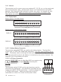
1.4.1 Sensors
The terminals used for sensor inputs are numbered Z1, Z2, Z3, etc. on the main board
and on the extension cards. Connect each sensor to a Z terminal and to the COM
terminal. Note that each COM terminal is used by two zones; for example, Z1 and
Z2 use the same COM. Make sure each sensor is connected to the proper COM.
False alarms can result if the wires are not properly connected.
1.4.2 Supply Inputs
Sensor Inputs on the Main Board:
Z1
COM
Z2
Z3
Z4
COM
Z5
COM
Z6
Z7
COM
Z8
ZONE INPUTS
Sensor Inputs on the Extension Cards:
CARD #1
Z9
COM
Z10
Z11
COM
Z12
Z13
COM
Z14
Z15
COM
Z16
COM
Z22
Z23
COM
Z24
ZONE INPUTS
CARD #2
Z17
COM
Z18
Z19
COM
Z20
Z21
ZONE INPUTS
1.4.2.1 Backup Battery Connection
The terminals marked BATTERY are used for the backup battery. The Agri-Alert
system uses a 12VDC/7Ah sealed lead acid battery. No other type of battery can be
used. The battery wires run through the tube provided, as shown in Figure 10.
Make sure the positive wire of the battery is connected to the positive terminal. See
Appendix B for normal battery life spans.
1.4.2.2 AC Power Connection
MAKE SURE that the Agri-Alert 9600 can operate using
only the battery supply BEFORE connecting the
transformer !
!
TRANSF.
RED
18
s
s
16VAC
+
BLACK
WIRE
(—)
-
BATTERY
SUPPLY INPUTS
AA-9600.rev.12
BLACK
RED
WIRE
(+)
WARNING
The terminals marked 16VAC on the main board are used for
connecting the transformer. The transformer provided with the
system is a 16VAC/150VA transformer. It must be plugged into
a 120VAC/60Hz outlet. Make sure the power source is
unswitched (i.e. there is no switch on the power outlet).
BATTERY
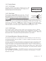
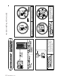
1.4.3 Terminal Outputs
1.4.3.1 0-10V Output
Terminals marked 0-10V supply a voltage from 0 to 10V
(25mA max) to an auxiliary device. The voltage can be
manually adjusted from the keyboard.
+
0-10V
-
+
SIREN
-
+
12VDC
-
OUTPUTS
1.4.3.2 Siren Output
The terminals marked SIREN are for the siren. The voltage supplied is 12VDC with a maximum current of 1A.
1.5 kOhms
1/2 W
The sound loudness of the siren should not exceed 120
decibels. Note that the battery must be hooked up if a
siren is used. Make sure the positive wire is connected to the positive terminal of the
siren. The siren circuit is monitored by the Agri-Alert system for defects and wire
troubles. This may not work properly if the impedance of the siren is too high. If this
is the case, you can add a 1.5k resistor (1/2W) to the siren circuit as close to the
siren as possible. If no siren is connected, connect a 1.5k resistor (1/2W) (included
with the system) to the siren output or disable siren monitoring (see 7.10.3).
1.4.3.3 12VDC Output
The terminals marked 12VDC provide 12VDC with a maximum current of 750mA.
This can be used to power other accessories such as temperature controllers. In the
event of a power failure, the battery backup provides 12VDC to this line. Make sure
the positive wire is connected to the positive terminal of your device.
1.4.4 External Microphone / Microphone Box Hookup
An external microphone or a microphone box can be hooked up for use with the onsite listening function (see your dealer). If neither is needed, the system uses a builtin internal microphone.
A jumper is provided on the main board for configuring the type of microphone used
for on-site listening. If neither the external microphone nor the microphone box is
needed, the jumper can be positioned at either position. Figure 11 shows the location
of the microphone jumper. Use caution when prying the jumper loose. Make sure the
jumper is placed horizontally on the top or bottom pins. Any other positions will lead
to poor results.
External Microphone Hookup – The SHIELD terminal is connected to the wire shielding. The SIGNAL and CASE terminals are connected to the microphone. The AUX
terminal is not used.
AA-9600.rev.12
19
Figure 11: Location of Microphone Jumper on Main Board
MICROPHONE
JUMPER
EXT.
AUX.
JUMPER ON
EXTERNAL MIC.
EXT.
AUX.
JUMPER ON
MIC. BOX
SHIELD
CASE
SIGNAL
AUX
MICROPHONE WIRE
MICROPHONE
Microphone Box Hookup – The SHIELD terminal is connected to the wire shielding.
The AUX terminal is connected to the microphone box. In addition, the microphone
box must be connected to the serial bus (see Section 1.5).
MICROPHONE
BOX
MICROPHONE
20
AA-9600.rev.12
SHIELD
CASE
SIGNAL
AUX
SHIELD
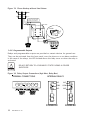
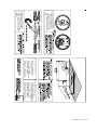
1.4.5 Phone Hookup
Two types of phone hookups are possible. In the simplest case, the Agri-Alert is
connected to the phone lines using an ordinary 6 contact phone jack (Canada: CA11;
USA: RJ11). The two wires from the phone line are connected to the LINE terminals
marked R and T. In this configuration, the user has priority over the system when
using the phone line: the system will wait for the line to free up before dialing out.
The best method is to use a line seizure modular jack designed for use with alarm
systems (Canada: CA31A or CA38A; USA: RJ31A or RJ38A). In this case, the
system has priority over other users when dialing out. A line seizure kit is available
from your dealer. The connections for this type of plug are shown in the figure below.
This plug disconnects all other phones on the line when dialing out in an emergency.
In order to do this, you must tap the phone line at its point of entry in the building.
Figure 12: Phone Hookup with Line Seizure
WALLJACK
4
PLUG
5
T
R
T1
3
6
2
7
1
R1
T1
T
R
R1
8
TOALLPHONELINES
AA-9600.rev.12
21
Figure 13: Phone Hookup without Line Seizure
THE TIP WIRE IS THE ONE WITH
THE MOST POSITIVE VOLTAGE
READING ON A VOLTMETER
TIP
RING
WALL JACK
PLUG
R
T
T
R
1.4.6 Programmable Outputs
Relays and programmable outputs are provided on certain devices for general use.
They can be activated from the front panel, over the phone or on an alarm condition.
In the case of the relays, the LED located above the relay turns on when the relay is
activated.
RELAYS RETURN TO A DISABLED STATE DURING A POWER
SHORTAGE.
!
WARNING
Figure 14: Relay Output Connections (Agri-Alert, Relay Box)
TERMINAL CONNECTIONS
INTERNAL RELAYS
N.C.
N.C.
COM.
COM.
N.O.
N.O.
DISABLED
22
AA-9600.rev.12
ENABLED
1.4.7 Connecting the Earth Ground
The earth ground terminal provides a ground for the AgriAlert system. Use a rod at least 5/8” (1.6cm) in diameter at
least 10’ (3m) long. The rod must have a clean metal surface free of paint, enamel or other nonconducting substances. Drive the rod at least 10’ (3m) into the ground. If
the bedrock is more than 47” (1.2m) deep, drive the rod into
the ground to bedrock level and bury any remainder horizontally at least 2’ (600mm) below ground level. If the bedrock
is less than 47” (1.2m) deep, bury the rod horizontally at
least 2’ (600 mm) below ground level.
EARTH
GROUND
3M METAL ROD
(ref. article 10-702, 3d of the Canadian Electricity Code C22.10-99)
Use a CSA certified wire of TEW type or a UL certified wire of type 1015: Green/
yellow, #12AWG, 600V, 105°C insulated wire. We suggest using a Belden #9912
(color code #189) or equivalent.
The rod must be connected to the wire described above. It is recommended to let the
rod going out of the ground to connect it. The wire length must not exceed 50’ (15m).
It is extremely important that the earth ground terminal be connected to
a proper ground to protect the electronic components from damage due
to lightning surges and electrostatic discharges. Do not use the electrical
ground for this purpose.
IF OUTDOOR CONNECTIONS ARE USED, MOUNT THE ENCLOSURE
AS CLOSE AS POSSIBLE TO THE ENTRY POINT OF THE OUTDOOR
WIRING.
!
WARNING
AN IMPROPER EARTH GROUND CONNECTION IMMEDIATELY
VOIDS THE SYSTEM WARRANTY WITHOUT FURTHER NOTICE.
0
0
0
0(7$//,&52'
0
!
0
0
0
%('52&.
AA-9600.rev.12
23
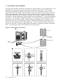
1.5 SERIAL BUS INTERFACE CONNECTIONS
1.5.1 Connecting Devices to the AA-9600
The serial bus interface is used to connect the different AgriAlert devices together. A shielded twisted pair cable is needed
for this purpose. Each device includes four terminals marked
SERIAL BUS and numbered from 1 to 4. Connect all the number
1 terminals together, all the number 2 terminals together, etc.
See Appendix C for cable gauge and maximum length recommendations.
1
2
3
4
SERIAL BUS
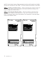
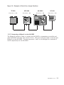
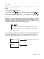
1.5.2 End of Line Jumpers
Each device includes an end of line jumper to identify the end of the communication
line. When a device is located at the end of the communication loop, the end of line
jumper must be at the YES position. For the other devices, place the jumper at the
NO position. The following diagram shows the location of the end of line jumper and
the communication terminals on the Agri-Alert.
Figure 15: Location of the End of Line Jumper and the Communication Terminals
END OF LINE
JUMPER
COMMUNICATION
TERMINALS
24
AA-9600.rev.12
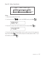
Figure 16: Example of End of Line Jumper Positions
TP 800
KPB 400
AA-9600
KP 400
End of line = YES
End of line = NO
End of line = NO
End of line = YES
1.5.3 Connecting a Bridge-A to the AA-9600
The Bridge-A module is used to connect the AA-9600 to temperature controller and
other AA-9600 networks (see section 3.4.3). Only two wires are used to connect the
Bridge-A to the AA-9600. Connect terminals 1 and 2 on the Bridge-A to terminals 2
and 3 respectively on the AA-9600.
AA-9600.rev.12
25
CHAPTER TWO: USER INTERFACE
The system displays and prompts for information by using the alphanumeric screen.
The keypad is used for data entry and for enabling and disabling the various system
functions. The speaker on the front panel delivers voice messages. A built-in piezoelectric warns of illegal entries (3 short beeps) and beeps once when a valid key is
pressed. The integrated microphone on the front panel is used to record the user ID
message and provide on-site listening. The status of some subsystems is displayed
using LEDs on the front panel.
2.1 FRONT PANEL
1
6
2
4
3
5
1 - Display Screen — An alphanumeric display used to provide information and
prompt for inputs.
2 - Cursor Keys — Used to step through menu items during data entry and for deleting the last character entered.
3 - Speaker — System identification and alarm messages.
4 - Integrated Microphone — Records the ID message and provides on-site listening
input.
5 - Keypad — User inputs and information requests.
6 - System LEDs — Status of various subsystems (see table on following page).
26
AA-9600.rev.12
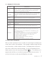
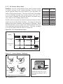
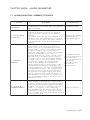
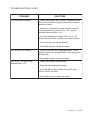
2.2 MEANING OF STATUS LEDS
L ED
MEA N I N G
A L A RM
This LED is a ctiva ted when one or more a la rm cond itions a re
d etected . The LED is turned off when the a la rm is a cknowled g ed a s
long a s the a la rm cond ition no long er exists, the reset time ha s
ela p sed a nd no other a la rms a re a ctive.
S TA N D B Y
This LED is a ctiva ted when the A g ri- A lert system is in sta nd b y mod e.
In this mod e, the system stop s monitoring the sensor inp uts for a la rm
cond itions. The LED is turned off when norma l monitoring is
resumed .
B Y PA S S
This LED is a ctiva ted when one or more zones a re b yp a ssed .
LED is turned off when no zones a re currently b yp a ssed .
A RM E D
This LED is a ctiva ted when the b urg la r zones a re a rmed .
ON L INE
This LED is a ctiva ted when the system uses the telep hone line.
16 V A C
FA I L U RE
The LED is a ctiva ted when a p ower fa ilure is d etected on the 16VA C
sup p ly circuit.
LO W
B A T T E RY
This LED is a ctiva ted when the b a ck- up b a ttery volta g e is low.
T RO U B L E
This LED is a ctiva ted when:
- a zone config ura tion conflicts with the sig na l received from the
sensor
- a wire short or op en circuit is d etected on a temp era ture or d ry
conta ct with EOLR inp ut.
- a n op en circuit is d etected on a d ry conta ct inp ut with DEOLR.
- a wire short is d etected on a d ry conta ct inp ut with DEOLR.
- a wire op en or short is d etected on a 4- 20mA inp ut.
- a softwa re p rob lem is d etected .
- a p rob lem on the mod ule's softwa re is d etected .
- a mod ule low SBI p ower.
- a communica tion p rob lem occured on a mod ule.
The
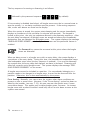
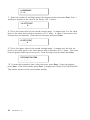
2.3 DISPLAYING A PARAMETER
When you select a parameter to input or modify, the system begins by displaying the
current value or status of the parameter. If the message to display is longer than the
size of the window, it will be scrolled to the left. The display pauses at the end of
each screen to allow time to read the message. You can exit prematurely from a
display sequence at any time by pressing the Cancel
key. This will place you in
program mode and allow you to modify the parameter values (see next section). To
exit from this function as well, press the Cancel key once again.
AA-9600.rev.12
27
If a parameter is not completely defined when you try to display it, the message
INCOMPLETE DATA appears on the screen. This may be an indication that the system will not behave as expected. If, for example, a zone input is not completely
configured, the system will not monitor the zone for alarm conditions. Before enabling
the system for normal operation, make sure all parameters are properly defined. In
the case of phone numbers and zones, the system will display a message periodically
telling the user which zones and phone numbers are incomplete. To exit from the
warning display, press the Cancel key.
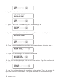
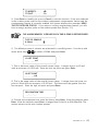
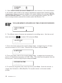
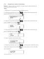
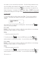
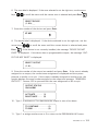
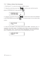
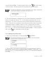
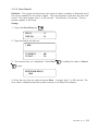
2.4 MODIFYING A PARAMETER
If you have selected a parameter and the display sequence is now finished, you can
begin modifying the parameter values. The following screen appears on the display:
TO MODIFY. . . . . (↵)
TO QUIT. . . . . . . (X)
This screen is also displayed if the display sequence described above was cancelled
prematurely. If you want to modify the parameter values at this point, press the Enter
key
to modify the parameter. The system will prompt for the information re-
quired to define the parameter. For example, if you select the Exit Delay parameter
followed by MODIFY, the system responds:
ENTER NEW DELAY
_ MIN: _ _ SEC
The number of spaces provided for input corresponds to the maximum number of
digits allowed. In this example, one space is provided for the minutes and 2 spaces
are provided for the seconds. The cursor positions itself on the first space and blinks
until a digit is entered. If no response is given within 2 minutes, the system will cancel the input session and return to the Date/Time display. If more than one value is
required in the same screen (in this example: hours and minutes), press Enter after
entering the first value to step to the following one. To enter a zero value, you cannot
simply press Enter; you must type 0 Enter.
28
AA-9600.rev.12
If you make a typing mistake, you can backstep using the back arrow key
under-
neath the display window before pressing Enter. The cursor will position itself accordingly. You can enter a negative value if this is allowed (for example, a negative temperature value) by pressing the +/- key
either before or after the digits.
After entering a value using the numerical keypad, press Enter to register the value. If
the value entered falls outside the permissible range for that parameter, the system
will beep three times and wait for you to modify the input using the back arrow key.
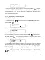
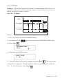
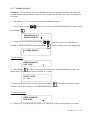
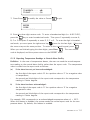
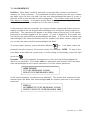
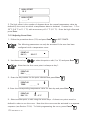
2.5 HOW TO USE THE MENUS
Menus are used to select a parameter or to assign a predetermined value to a parameter. If the menu is comprised of only two items, they are displayed on the screen at
once. For example, when you press the Clock key
QZ-
Clock
, followed by Enter to modify,
the following menu appears:
DATE . . . . . . . . . (1)
TIME . . . . . . . . . (2)
You simply type the number of the item to select that item (no need to press the Enter
key). When more than two menu items are involved, the system will display one item
at a time and allow the user to scroll through the menu using the up and down-arrow
keys
. Each menu item is followed by an arrow symbol to locate the current
position in the menu. Once a menu item is selected, other sub-menus may appear to
further define the input. For example, if you press the System key
, the following
sub-menu appears:
SYSTEM
PROGRAM ZONES
AA-9600.rev.12
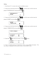
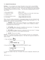
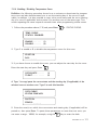
29
The first menu item is PROGRAM ZONES. The arrow following the item means you are
at the top of the menu. If you press the down-arrow
, the second item appears:
SYSTEM
PROGRAM DIALING
The arrows indicate that menu items are to be found above and below the current
item. When you reach the end of the menu, the last item will have an up-arrow . To
select a menu item, press Enter.
30
AA-9600.rev.12
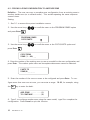
CHAPTER THREE: SYSTEM INITIALIZATION
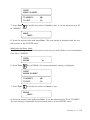
3.1 SYSTEM INSTALLATION MENUS
The system installation menus can be accessed using the System key. An installer
password is needed. This password must be entered when the INSTALLATION menu
item is selected in the SYSTEM menu. By default, the installer password is set to 9601.
Access to System Installation Menus:
1. Press the System key
. The current revision of the software is displayed. The
installer password must be entered.
SOFTWARE
REV. x.xxx
ENTER INSTALLER
PASSWORD: _ _ _ _
2. Enter the installer’s password (9601 by default) and press Enter
.
SYSTEM
PROGRAMME ZONES
3. Using the up and down-arrow keys
and press Enter
, scroll the menu to the desired item
.
To change the installer password:
1. Follow the preceding procedure to access the system installation menus.
2. Using the up and down-arrow keys
, scroll the menu until the item
displayed is PROGRAM SYSTEM and press Enter
.
SYSTEM
PROGRAM SYSTEM
3. Using the up and down-arrow keys
displayed is INST. PASSWORD and press Enter
, scroll the menu until the item
.
AA-9600.rev.12
31
PROGRAM SYSTEM
INST. PASSWORD
4. Enter a four-digit code and press Enter
. The system prompts for the pass-
word a second time.
ENTER NEW
PASSWORD: _ _ _ _
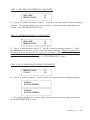
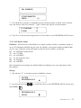
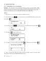
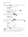
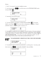
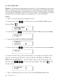
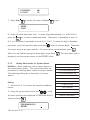
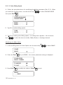
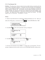
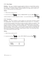
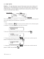
3.2 EXTENSION CARD INITIALIZATION
If you have purchased one or two extension cards with your system, you must initialize them by following the procedure given below.
1. See Section 3.1 to access the system installation menus.
2. Using the up and down-arrow keys
played is PROGRAM AUX’S and press Enter
, scroll the menu until the item dis.
PROGRAM AUX’S
EXTENSION CARD
3. Using the up and down-arrow keys
played is EXTENSION CARD and press Enter
, scroll the menu until the item dis.
CARD #1
STATUS: DISABLE
CARD #2
STATUS: DISABLE
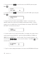
4. The system displays the current status of the extension cards.
TO MODIFY. . . . .
TO QUIT. . . . . . .
5. Press Enter
32
AA-9600.rev.12
(↵)
(X)
to modify or Cancel
to quit.
CASE 1: NO CARDS ARE PRESENTLY INITIALIZED
ADD CARD
. . . . . . . (1)
REMOVE CARD . . . . . . (2)
6. Type 1 to initialize extension card # 1. Type 2 to exit this function without making
changes. The system displays the current status of the parameters once again and
returns to the PROGRAM AUX’S menu.
CASE 2: EXTENSION CARD # 1 IS INITIALIZED
ADD CARD
. . . . . . . (1)
REMOVE CARD . . . . . . (2)
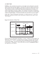
6. Type 1 to add extension card # 2. Type 2 to remove extension card # 1. Press
the Cancel key to exit this function without making changes. Extension cards must
be removed if you are planning to unplug the extension card from the main board to
make changes in the configuration. The system displays the current status of the
parameters once again and returns to the PROGRAM AUX’S menu.
CASE 3: BOTH CARDS ARE PRESENTLY INITIALIZED
REMOVE CARD . . . . . . . (1)
TO QUIT . . . . . . . . . . . . (2)
6. Type 1 to remove card #2. Type 2 to exit this function without making changes.
CARD #1
STATUS: ENABLE
CARD #2
STATUS: DISABLE
7. The system displays the current status of the parameters once again and returns
to the PROGRAM AUX’S menu.
AA-9600.rev.12
33
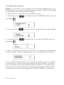
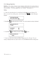
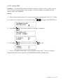
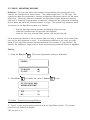
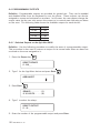
3.3 DEVICE INITIALIZATION
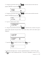
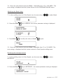
3.3.1 Add Device to Network
Each device connected to the Agri-Alert network must be identified by the user in
order for the system to recognize it. Normally, this is done during installation, after
the connections have been made. A device can also be added to an existing system.
If this is the case, the procedure below must be followed before connecting the new
device to the system.
1. See Section 3.1 to access the system installation menus.
SYSTEM
PROGRAM AUX’S
2. Using the up and down-arrow keys
, scroll the menu until the item
displayed is PROGRAM AUX’S and press Enter
.
PROGRAM AUX’S
DEVICE
2. Using the up and down-arrow keys
displayed is DEVICE and press Enter
, scroll the menu until the item
.
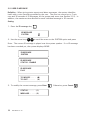
DEVICE
ADD
3. Press Enter
once again to select the ADD option.
SELECT DEVICE
(2..99) : _ _
5. Enter the device ID number and press Enter. The number 1 is reserved for the
AA9600; the number 99 is reserved for the Bridge communication module.
DEVICE CONNECTED
AND ID SET ?
YES . . . . . . . . . . . (1)
NO . . . . . . . . . . . (2)
34
AA-9600.rev.12
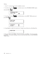
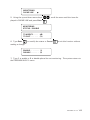
6. Type 1 if the device is already connected to the network; the system continues
with step 9. Type 2 if either the device is not yet connected to the network or the id
number has not been configured.
SBI DISABLED
CONNECT DEVICE
# XX NOW
IF CONNECTED
PRESS. . . . . . . . . .(1)
7. The serial bus interface is disabled and the system pauses to allow you to make
the connections. Type 1 to continue the installation procedure, once the device is on
line. Press cancel to end the procedure without adding the new device.
CONFIGURE DEVICE
ID TO #XX
IF CONFIGURED
PRESS. . . . . . . .
(1)
8. At this point, you must configure the id number on the new device. Refer to the
installation manual of the device to do this. When you are finished, type 1. Press
Cancel to end the procedure without adding the new device. When a new device is
installed, the system checks if it responds normally. The message “DEVICE #XX
INSTALLED” is displayed if the device exists; otherwise the message “DEVICE DOES
NOT EXIST” is displayed.
TO CONTINUE . . . (1)
TO END. . . . . . . . (2)
9. Type 1 to continue adding devices or 2 to return to the PROGRAM AUX’S menu.
AA-9600.rev.12
35
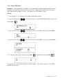
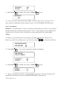
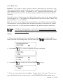
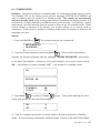
3.3.2 Remove Device from Network
Follow the procedure below to remove a device before disconnecting it from the
network.
1. See Section 3.1 to access the system installation menus.
2. Using the up and down-arrow keys
displayed is PROGRAM AUX’S and press Enter
, scroll the menu until the item
.
PROGRAM AUX’S
DEVICE
3. Use the arrow keys
to scroll the menu to the DEVICE option and press Enter.
DEVICE
REMOVE
4. Use the arrow keys
to scroll the menu to the REMOVE option and press Enter.
SELECT DEVICE
(2..99) : _ _
5. Enter the device identification number and press Enter. The number 1 is reserved
for the AA9600; the number 99 is reserved for the Bridge communication module. If
the number entered is not a valid device number, the message “DEVICE DOES NOT
EXIST” is displayed and the system goes to step 8.
DISCONNECT DEVICE
# XX NOW ?
YES . . . . . . . . . . . (1)
NO . . . . . . . . . . . (2)
6. Type 1 if you would like to disconnect the device right now. Type 2 to disconnect
the device at a later time; the system ends the procedure.
36
AA-9600.rev.12
SBI DISABLED
IF DISCONNECTED
PRESS . . . . . . . . . . (1)
7. The serial bus interface is disabled and the system pauses to allow you to disconnect the device from the network. Type 1 when the device is disconnected.
TO CONTINUE . . . (1)
TO END. . . . . . . . (2)
8. Type 1 to continue removing devices or 2 to return to the PROGRAM AUX’S menu.
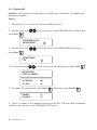
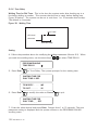
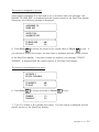
3.3.3 Edit Device Label
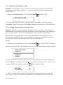
Definition: Each device is identified by a unique number and by a character string of
up to 32 characters defined by the user. By default, the system defines a label made
up of a two-character string followed by the device id number, as follows:
KP TP LB EC BG RB -
for a KPB-400 and KP-400
for a TP-800
for a LB-9600
for an extension card
for a Bridge
for a RB-800
We recommend not erasing the default label and adding your own description after
the default.
Setting:
1. See section 3.1 to access system installation menus.
SYSTEM
PROGRAM AUX’S
2. Use the arrow keys
press Enter
to scroll the menu to the PROGRAM AUX’S option and
.
PROGRAM AUX’S
DEVICE
AA-9600.rev.12
37
3. Use the arrow keys
Enter
to scroll the menu to the DEVICE option and press
.
DEVICE
EDIT LABEL
4. Use the arrow keys
Enter
to scroll the menu to the EDIT LABEL option and press
.
SELECT DEVICE
(1..99): _ _
5. Enter the device ID number and press Enter. Number 1 is reserved for the
AA9600; number 99 is reserved for the Bridge communication module. If the ID
number is not an installed device, the system displays the message “DEVICE DOES
NOT EXIST” and continues with step 7.
TP#08
BREEDER#01
6. Use the numeric keys to type the device label. For example, the number 2 key is
used to type the letters A, B and C: type 2 for A, 22 for B, 222 for C, 2222 for a,
22222 for b and 222222 for c. Use the number 1 key for special characters. Use
the arrow keys
to move around the display. Press Enter
to end
the edit session.
TO CONTINUE . . . (1)
TO END. . . . . . . . (2)
7. Type 1 to continue editing device labels or 2 to return to the PROGRAM AUX’S menu.
38
AA-9600.rev.12
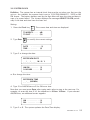
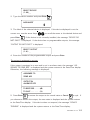
3.3.4 Upload Data To/From a UP-1000
Definition: This function is used to transfer a complete AA-9600 parameter configuration to or from a UP-1000 programmer. The procedure is as follows: (i) connect the
UP-1000 to the SBI on the AA9600 using the interface card (see UP-1000 manual);
(ii) place the AA9600 in UP-1000 mode; (iii) select the memory banks on the UP1000; (iv) select Protocol 1 on the UP-1000 and press READ or WRITE.
1. See Section 3.1 to access the system installation menus.
SYSTEM
PROGRAM AUX’S
2. Use the arrow keys
press Enter
to scroll the menu to the PROGRAM AUX’S option and
.
PROGRAM AUX’S
UPLOAD
3. Use the arrow keys
to scroll the menu to the UPLOAD option and press Enter.
UPLOAD
UP-1000
4. Use the arrow keys
Enter
to scroll the menu to the UP-1000 option and press
. During the transfer, the message “TRANSFER IN PROGRESS” is displayed.
AA-9600.rev.12
39
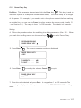
3.3.5 Upload Data to a Device
Definition: This function is used to update one or more newly installed devices. This
greatly speeds up the process of updating the device network. Make sure the SBI bus
is connected on the new device before uploading.
1. See Section 3.1 to access the system installation menus.
2. Use the arrow keys
press Enter
to scroll the menu to the PROGRAM AUX’S option and
.
PROGRAM AUX’S
UPLOAD
3. Use the arrow keys
to scroll the menu to the UPLOAD option and press Enter.
UPLOAD
AUX DEVICES
4. Use the arrow keys
press Enter
to scroll the menu to the AUX. DEVICES option and
.
ALL . . . . . . . . . . . (1)
SPECIAL . . . . . . . (2)
5. Type 1 to upload the new data to all the devices. The upload is performed and the
function is exited. Type 2 to upload the data to one or certain devices in particular.
ONE DEVICE . . . . . . . . . (1)
RETRANSMIT . . . . . . . . (2)
6. If you typed 2 at step 5 above, you can choose to upload to a device in particular.
In this case, type 1 and the system will prompt for the device number. The second
option is used when errors occur during an upload to all devices. By using this function, the user can redo the upload only to those devices that have not been updated.
If all devices are up-to-date, the message “NO DEVICE IN TROUBLE” is displayed.
40
AA-9600.rev.12
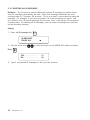
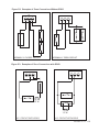
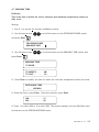
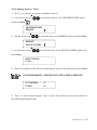
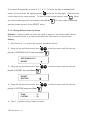
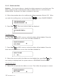
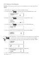
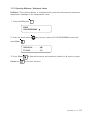
3.3.6 Upload Data to an AA9600
Definition: This function is used to upload a complete
parameter configuration from one AA9600 to another
AA9600. The procedure is as follows: (i) place the
AA9600 that will receive the new data in download
mode; (ii) connect the SBI bus between the two
AA9600s as illustrated beside; (iii) place the AA9600
that will transmit the data in upload mode.
6(5,$/%86
6(5,$/%86
$$
$$
1. See Section 3.1 to access the system installation menus.
2. Use the arrow keys
press Enter
to scroll the menu to the PROGRAM AUX’S option and
.
PROGRAM AUX’S
UPLOAD
3. Use the arrow keys
to scroll the menu to the UPLOAD option and press Enter.
UPLOAD
AA9600
4. Use the arrow keys
to scroll the menu to the AA-9600 option and press Enter.
UPLOAD . . . . . . . . . . . . (1)
DOWNLOAD. . . . . . . . . (2)
5. Type 1 to place the AA9600 in transmit mode or 2 to place the AA9600 in receive
mode. During the upload, the message “UPLOAD IN PROGRESS” is displayed on the
AA9600 that is transmitting the data; the message “DOWNLOAD IN PROGRESS” is
displayed on the AA9600 that is receiving the data.
AA-9600.rev.12
41
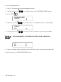
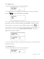
3.3.7 Display Device Information
Definition: This function is used to display zones assigned to each device.
1. See Section 3.1 to access the system installation menus.
to scroll the menu to the PROGRAM AUX’S option and
2. Use the arrow keys
press Enter
.
PROGRAM AUX’S
INFORMATION
3. Use the arrow keys
press Enter
to scroll the menu to the INFORMATION option and
.
INFORMATION
DEVICE
4. Use the arrow keys
to scroll the menu to the DEVICE option and press Enter.
SELECT DEVICE
(1..99): _ _
5. Enter the number of the device and press Enter. The number 1 is reserved for the
AA9600; the number 99 is reserved for the Bridge communication module.
KP #02
BARN 3
6. The device label is displayed. If the device selected is not the right one, use the
to scroll the menu until the correct device is selected and press
arrow keys
Enter
. If the device is not correctly installed, the message “NO DEVICE “ is
displayed and the system prompts for a new device (step 5).
KP#02
ZONE 22,23,24,25
7. The zones assigned to the device are displayed. The system then returns to the
system installation menu.
42
AA-9600.rev.12
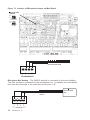
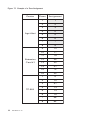
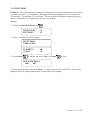
3.4 ZONE ASSIGNMENTS
Definition: The Agri-Alert can have up to 96 separate zone inputs. The first 8 zones
are reserved for the 8 basic zones on the Agri-Alert and cannot be changed. Zones 996 are spread across several devices and must be assigned at the time of installation.
Assignments can be done manually or automatically. Figure 17 gives an example of a
manual zone assignment.
Setting:
1. See 3.1 to access the system installation menus.
SYSTEM
PROGRAM ZONES
2. Use the arrow keys
press Enter
to scroll the menu to the PROGRAM ZONES option and
.
PROGRAM ZONES
ASSIGN
3. Use the arrow keys
Enter
to scroll the menu to the ASSIGN option and press
.
MANUAL . . . . . . . . . . . (1)
AUTO . . . . . . . . . . . . . . (2)
4. Type 1 to do a manual assignment (3.4.1) or 2 to do an automatic assignment
(3.4.2).
AA-9600.rev.12
43
Figure 17: Example of a Zone Assignment
D evi ce
Zones
A ssi gnment
1
1
2
2
3
3
4
4
5
5
6
6
7
7
8
8
9
12
10
17
11
18
12
39
13
20
14
21
15
72
16
23
1
9
2
10
3
51
4
13
5
14
6
15
7
96
8
64
A gri -A lert
E xtensi on
C ard #1
TP -800
44
AA-9600.rev.12
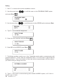
3.4.1 Manual Assignment
SELECT ZONE
(9..96): _ _
5. Enter the zone number and press Enter
.
SELECT DEVICE
(1..99): _ _
6. Enter the device number and press Enter
in Section 3.3.
. Device assignments are explained
SELECT DEVICE’S
ZONE (1..X): _
7. Enter the zone number on the device and press Enter
.
TO CONTINUE. . . . . . . . (1)
TO END. . . . . . . . . . . . (2)
8. Type 1 to do another manual assignment or 2 to quit this function.
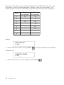
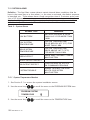
3.4.2 Automatic Assignments
In the case of automatic assignments, the user selects a device and enters the number
of zones to be assigned for the device. Zones are assigned in the order that they
physically appear on the device using the next available number in the sequence 9..96.
Zones on the device that have previously been assigned are not reassigned.
Example: The following table shows an example
of zone status before an automatic assignment is
performed.
Device
Zones
Status
Agri-Alert
1-8
reserved
9
available
10-18
assigned
19-43
available
44
assigned
45-55
assigned
56-96
available
Other
Devices
AA-9600.rev.12
45
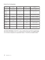
Now let’s say we want to an automatic assignment on a TP-800 with 8 zones. Suppose zones 1 and 3 are already assigned to zones 10 and 44 on the system. The
following table shows zone status before and after the automatic zone assignment.
Zone
Before
Assi gnment
After
Assi gnment
1
10
10
2
-
9
3
44
44
4
-
19
5
-
20
6
-
21
7
-
-
8
-
-
Setting:
SELECT DEVICE
(1..99): _ _
6. Enter the device number and press Enter
. Device assignments are explained
in Section 3.3.
NUMBER OF ZONES
(1..X): _ _
7. Enter the number of zones to assign and press Enter
46
AA-9600.rev.12
.
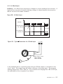
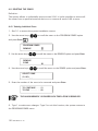
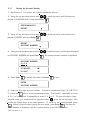
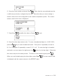
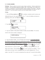
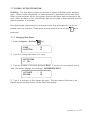
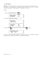
3.4.3 Assigning an External Zone
Definition: The Bridge-A communication device can be used to provide external zone
inputs to the AA-9600. Using external inputs saves on costly wiring by tapping in on an
existing wiring installation. Zone inputs can come from another AA-9600 system or
from a temperature controller. For example, two AA-9600 systems can use the same
zone input while defining separate settings for declaring alarms. Up to four AA-9600
systems can be connected together in this way. The Bridge-A also provides computer
and modem connection possibilities (see Section 1.5.3 to connect the Bridge-A module
to the AA-9600).
Figure 18: Example of Bridge-A Connection
In the example above, local zone 2 is assigned to input 3 of the temperature controller
connected to card 1 on the Bridge-A. Local zone 44 is assigned to zone 93 of the
AA9600 connected to card 2 on the Bridge-A. Local zone 17 has its own zone input.
AA-9600.rev.12
47
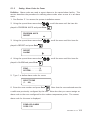
Setting:
1. See 3.1 to access the system installation menus.
2. Use the arrow keys
and press Enter
to scroll the menu to the PROGRAM ZONES option
.
PROGRAM ZONES
ASSIGN
3. Use the arrow keys
to scroll the menu to the ASSIGN option and press Enter.
MANUAL . . . . . . . . . . . (1)
AUTO . . . . . . . . . . . . . . (2)
4. Type 1 to do a manual assignment.
SELECT ZONE
(9..96): _ _
5. Enter the zone number and press Enter
.
SELECT DEVICE
(1..99): _ _
6. Enter 99 for the BRIDGE press Enter
.
SELECT CARD
(1..4): _ _
7. The Bridge module contains up to four Combridge cards used to communicate with
external networks. These cards are numbered from 1 to 4 from left to right inside the
Bridge enclosure. Enter the number of the card which communicates with the device
you will be using to assign the zone.
EXTERNAL AA9600?
YES . . . . . . . . . . . . .
NO . . . . . . . . . . . . . .
(1)
(2)
8. Type 1 if this card is communicating with another AA9600 system, or 2 if this is
another type of card.
48 AA-9600.rev.12
AA9600 card:
EXTERNAL ZONE
# (1..96): _ _
9. Enter the zone number on the external AA9600 that will be assigned to the local
zone and press Enter.
Other Cards:
CONTROL ID: _ _ _
INPUT #: _ _ _
9. Enter the controller id number from 1 to 199 (refer to the id jumper position on the
Comlink card inside the controller enclosure) and press Enter; enter the number of the
input to use on the controller and press Enter.
TO CONTINUE. . . . . . . . (1)
TO QUIT . . . . . . . . . . . . (2)
10. Type 1 to proceed with another zone assignment or 2 to quit this function.
AA-9600.rev.12
49
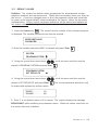
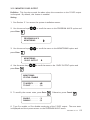
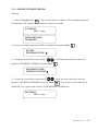
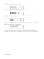
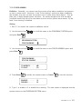
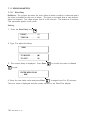
3.5 SBI INITIALIZATION
3.5.1 Disable SBI in Case of Low Battery
Definition: The Agri-Alert uses the backup battery in case of a power failure. When
the battery level is low, the user can choose to disable communication and interrupt
power to the devices to prolong the operating time of the Agri-Alert system. By
default, this parameter is set to SBI DEACTIVATED ON LO BATTERY.
Setting:
1. See Section 3.1 to access the system installation menus.
2. Use the arrow keys
press Enter
to scroll the menu to the PROGRAM AUX’S option and
.
PROGRAM AUX’S
SBI
2. Use the arrow keys
to scroll the menu to the SBI option and press Enter
.
SBI
POWER
at the POWER option.
3. Press Enter
SBI DEACTIVATED
ON LO BATTERY
TO MODIFY. . . . .
TO QUIT. . . . . . .
(↵)
(X)
4. To modify the current setting, press Enter
. Otherwise, press Cancel
.
SBI OFF ON LO BATTERY?
YES . . . . . . . . . . . . .
NO . . . . . . . . . . . . . .
(1)
(2)
5. Type 1 to disable the SBI or 2 to keep operating the SBI in case of a power failure.
The system returns to the PROGRAM AUX’S menu.
50
AA-9600.rev.12
3.5.2 Adjust SBI Speed
Definition: This parameter is useful if you experience frequent communication errors
between the Agri-Alert and the external devices. Reducing the SBI speed considerably reduces the number of errors. By default, the SBI speed is high.
Setting:
1. See Section 3.1 to access the system installation menus.
2. Use the arrow keys
press Enter
to scroll the menu to the PROGRAM AUX’S option and
.
PROGRAM AUX’S
SBI
3. Use the arrow keys
to scroll the menu to the SBI option and press Enter.
SBI
SPEED
4. Use the arrow keys
to scroll the menu to the SPEED option and press Enter.
SBI SPEED
HI
TO MODIFY. . . . .
TO QUIT. . . . . . .
(↵)
(X)
5. To modify the current speed, press Enter
. Otherwise, press Cancel
.
HI . . . . . . . . . . . . . . . . . (1)
LO . . . . . . . . . . . . . . . . (2)
6. Type 1 for a fast speed and 2 for a slow speed. The system returns to the PROGRAM AUX’S menu.
AA-9600.rev.12
51
3.5.3 Monitor SBI
Definition: This function sounds the alarm if the SBI supply is defective. By default, this
parameter is enabled.
Setting:
1. See Section 3.1 to access the system installation menus.
2. Use the arrow keys
press Enter
to scroll the menu to the PROGRAM AUX’S option and
.
PROGRAM AUX’S
MONITORING
3. Use the arrow keys
press Enter
to scroll the menu to the MONITORING option and
.
MONITORING
SBI
4. Use the arrow keys
to scroll the menu to the SBI option and press Enter
.
MONITORING
STATUS: ENABLE
TO MODIFY. . . . .
TO QUIT. . . . . . .
(↵)
(X)
5. To modify the current state, press Enter
. Otherwise, press Cancel
.
ENABLE. . . . . . . . (1)
DISABLE . . . . . . . (2)
6. Type 1 to enable, or 2 to disable monitoring of the SBI. The new state is displayed
and the system returns to the PROGRAM AUX’S menu.
52
AA-9600.rev.12
3.6 SYSTEM CLOCK
Definition: The system has an internal clock that must be set when you first turn the
unit on. As a default, the system clock is set to 12:00 PM JANUARY 1, 2003 in AM/
PM format. The battery backup used by the Agri-Alert will keep the time and date in
case of a power failure. The system displays the message ADJUST CLOCK periodically if the date and time have not been set.
Setting:
1. Press the Clock key
QZ-
Clock
. The current date and time are displayed.
TO MODIFY. . . . .
TO QUIT. . . . . . .
2. Type Enter
(↵)
(X)
to modify the current settings.
DATE
. . . . . . . . .(1)
TIME. . . . . . . . .
(2)
3. Type 1 to change the date:
ENTER NEW DATE
__/__/____ M/D/Y
AM/PM . . . . . . . . (1)
24 HOURS . . . . . . (2)
or 2 to change the time:
ENTER NEW TIME
_ _ : _ _ (HR:MIN)
4. Type 1 for AM/PM time or 2 for 24-hours time.
Note that you must press Enter after typing each value to step to the next one. For
example, to enter the time 9:14, the sequence is: 9 Enter 14 Enter. If you selected
AM/PM time, an additional screen appears:
AM . . . . . . . . . . . . (1)
PM . . . . . . . . . . . . (2)
5. Type 1 or 2. The system updates the Date/Time display.
AA-9600.rev.12
53
3.7 TEMPERATURE UNITS
Definition: Temperatures can be displayed either in Fahrenheit or Celsius units. All
temperatures will be displayed according to this definition. The default is Fahrenheit.
Setting:
1. Press the oC/oF key
o
TUV
. The current value is displayed.
F
TO MODIFY. . . . .
TO QUIT. . . . . . .
(↵)
(X)
2. To modify the current temperature units, press Enter
Cancel
. Otherwise, press
.
CELSIUS . . . . . . . . . . . . (1)
FAHRENHEIT. . . . . . . . . (2)
3. Type 1 for Celsius units, or 2 for Fahrenheit units. The new unit is displayed and
the system returns to the Date/Time display.
54
AA-9600.rev.12
3.8 DISPLAY CONTRAST
Setting:
1. Press the System key
. The current revision number of the software program
is displayed. The installer password must then be entered.
ENTER INSTALLER
PASSWORD: _ _ _ _
2. Enter the installer password (9601 by default) and press Enter
.
SYSTEM
PROGRAM SYSTEM
, scroll the menu until the item
3. Using the up and down-arrow keys
displayed is PROGRAM SYSTEM and press Enter
.
PROGRAM SYSTEM
CONTRAST
, scroll the menu until the item dis-
4. Using the up and down-arrow keys
played is CONTRAST. Type Enter
to modify the display contrast or Cancel
to exit this function.
CONTRAST
80%
80%
TO SAVE . . . . . . . . . . . (↵)
5. Use the up-arrow key
key
to increase the contrast. Use the down-arrow
to decrease the contrast. When you are finished, type Enter to save the new
setting. The system displays the new setting as a percentage. The final setting is
displayed and the system returns to the PROGRAM SYSTEM display.
AA-9600.rev.12
55
3.9 USER ID MESSAGE
Definition: When giving status reports and alarm messages, the system identifies
itself with a voice recording provided by the user. The user can record up to 7 minutes and 30 seconds of ID messages for the system and zones (see Section 3.10). In
addition, the maximum time allowed for each individual message is 30 seconds.
Setting:
1. Press the ID message key
DEF
ID message
.
ID MESSAGE
SYSTEM
2. Use the arrow keys
to scroll the menu to the SYSTEM option and press
Enter. The current ID message is played over the system speaker. If no ID message
has been recorded yet, the system displays NONE.
ID MESSAGE
SYSTEM
ID MESSAGE
STATUS: ENABLE
ID MESSAGE
PLAY
TO MODIFY. . . . .
TO QUIT. . . . . . .
(↵)
(X)
3. To modify the current message, press Enter
STATUS . . . . . . . .(1)
MESSAGE . . . . . . (2)
56
AA-9600.rev.12
. Otherwise, press Cancel
.
To Modify ID Message:
4. Type 2 to modify ID Message.
VOICE MEMORY
TOTAL: 7 MIN, 30 SEC
FOR RECORDING
PRESS 3 AND HOLD
5. Press the ID message key
DEF
ID message
and hold while you speak the message into the
microphone on the front panel.
VOICE MEMORY
ID: 30 SEC
6. The screen will count down from the maximum time remaining for one id messages until the ID message key is released.
ID MESSAGE
PLAY
7. The new message is played over the speaker and the system returns to the Date/
Time display.
To Enable / Disable ID Message:
STATUS . . . . . . . .(1)
MESSAGE . . . . . . (2)
4. Type 1 to enable or disable the ID Message.
ENABLE. . . . . . . . (1)
DISABLE . . . . . . . (2)
5. Type 1 to enable, or 2 to disable the ID Message. The new state is displayed and
the system returns to the Date/Time display.
AA-9600.rev.12
57
3.10 DELETING ALL ID MESSAGES
Definition: This function is used to delete the system ID message as well as all the
zone ID messages recorded by the user. Each new message decreases the total
recording time of 7 minutes, 46 seconds. This is true even if you rerecord a particular
message. For example, if you have recorded a 10 second message for zone 1 and
you record a new 10 second message for this zone, zone 1 will occupy 20 seconds of
recording time. By deleting all id messages, you can erase recording errors and free
up the recording memory.
Setting:
1. Press the ID message key
DEF
ID message
.
ID MESSAGE
ERASE ALL
2. Use the arrow keys
Enter
to scroll the menu to the ERASE ALL option and press
.
YES . . . . . . . . . . . . .
NO . . . . . . . . . . . . . .
(1)
(2)
3. Type 1 to erase all ID messages or 2 to quit this function.
58
AA-9600.rev.12
3.11 DEFAULT VALUES
Definition: The system has default values programmed for all parameters except
telephone numbers and user passwords. These values are present when you first turn
the unit on. If you have changed some or all of the parameter values and would like
to return to the original default values initialized at the factory, follow the procedure
outlined below. All the current parameter definitions will be erased and replaced by
the default values. Table 1 gives the default values for all system parameters.
1. Press the System key
. The current revision number of the software program
is displayed. The installer password must then be entered.
ENTER INSTALLER
PASSWORD: _ _ _ _
2. Enter the installer password (9601 by default) and press Enter
.
SYSTEM
PROGRAM SYSTEM
3. Using the up and down-arrow keys
played is PROGRAM SYSTEM and press Enter
, scroll the menu until the item dis.
PROGRAM SYSTEM
SET DEFAULTS
4. Using the up and down-arrow keys
played is SET DEFAULTS and press Enter
, scroll the menu until the item dis. The current parameter definitions will
be erased and replaced by default values.
TO SET . . . . . . . . (1)
TO QUIT . . . . . . . (2)
5. Enter 1 to set default values or 2 to cancel. The system displays the message
PLEASE WAIT while initializing the parameter values. When the screen turns back on,
the system has been initialized.
AA-9600.rev.12
59
Table 1: Default Values
PA RA MET ER
TEMPERATURE UNITS
o
F
U S ER
V A L UE
RA N G E
o
F / oC
12:00 PM
----
A M/PM
A M/PM or 24-HOURS TIME
DATE
SAT JA N 1,
2003
----
MUTE
DISA BLED
ENA BLED / DISA BLED
ID MESSA GE
DISA BLED
ENA BLED / DISA BLED
BUSY LINE TRIES
1
0 TO 3 tries
RING UNTIL A NSWER
8
1 TO 20 ring s
A NSWERING MA CHINE
DISA BLED
ENA BLED / DISA BLED
LINE SEIZURE
DISA BLED
ENA BLED / DISA BLED
3
2 TO 15 times
CA LL STA RT DELAY
1 min.
0 TO 59 minutes
TIME BETWEEN CA LLS
1 min.
0 TO 59 minutes
7
1 TO 7
WA ITING TIME FOR DIA L TONE
4 sec.
1 to 15 second s
PA USE DELAY KEY
4 sec.
1 to 255 second s
PULSE/TONE
TONE
PULSE/TONE
ENA BLED
ENA BLED / DISA BLED
80mS
50 to 250 mS
MA KE
39 mS
10 to 100 mS
BREA K
61 mS
10 to 100 mS
0.8 sec.
0.6 to 3 second s
CLOCK
TIME
D EFA U LT
V A L UE
MODE
MESSA GE REPETITIONS
# OF CA LL REPETITIONS
PHONE LINE CUT
MONITORING
DTMF SPEED
PULSE SPEED
INTERDIGIT
60
AA-9600.rev.12
- PA RA ME T E R
U S ER
V A L UE
RA N G E
30 sec.
0 TO 59 second s
DISA BLED
ENA BLED / DISA BLED
DISA BLED
ENA BLED / DISA BLED
SIREN DELAY
0 min.
0 to 20 minutes
SIREN TIME ON
5 min.
1 to 20 minutes
ENA BLED
ENA BLED / DISA BLED
30 sec.
0 to 5 minutes, 59 second s
1 min
0 to 5 minutes, 59 second s
RECA LL TIME
30 min.
from 10 min. to 12 hours, 59 minutes
A LA RM MEMORY
EMPTY
TROUBLE INFORMATION
EMPTY
ON-SITE
LISTENING
TIME
D E FA U LT
V A L UE
STATUS
RESTORE CA LLS
SIREN MONITORING
ENTRY DELAY
EXIT DELAY
DELAY
30 min.
0 to 59 minutes, 0 to 59 second s
STATUS
ENA BLED
ENA BLED / DISA BLED
0°
-10° TO 10° (F/C)
OFFSET
5°F
0°F - 36°F
STATUS
DISA BLED
ENA BLED / DISA BLED
ZONE 1
1 to 96
DISA BLED
ENA BLED / DISA BLED
50%
10 TO 100% in step s of 10%
HI
LO / HI
DEA CTIVATED
A CTIVATED / DEA CTIVATED
SBI MONITORING
ENA BLED
ENA BLED / DISA BLED
12VDC MONITORING
ENA BLED
ENA BLED / DISA BLED
FORCE A RMING
DISA BLED
ENA BLED / DISA BLED
16 VA C
FA ILURE
T° PROBE CA LIBRATION
OUTDOOR T°
COMPEN.
OUTDOOR PROBE
RELAY OUTPUTS #1 & #2
DISPLAY CONTRA ST
SBI SPEED
SBI STATE ON LOW BATTERY
AA-9600.rev.12
61
Default Zone Configurations
PA RA ME T E R
ZONE 1
ZONE 2
Z O N ES 3 - 96
RA N G E
OUTDOOR
TEMPERATURE
DRY CONTA CT
TEMPERATURE
DRY CONTA CT/TEMP./420mA /A C CURRENT/0-5V
OPEN /
CLOSED
CIRCUIT
----
N.C.
----
N.O. / N.C.
END OF LINE
RESISTOR
----
WITHOUT EOLR
----
WITH / WITHOUT EOLR
DIA LOUT
ENA BLED
ENA BLED
ENA BLED
ENA BLED / DISA BLED
SIREN
ENA BLED
ENA BLED
ENA BLED
ENA BLED / DISA BLED
1 min.
1 min.
1 min.
0 to 59 hours, 0 to 59
minutes, 0 to 59 second s
LOW SET
POINT
----
----
50°F
-40°F to 149°F
HIGH SET
POINT
----
----
85°F
-40°F to 149°F
CRITICA L
TEMPERATURE
----
----
95°F
-40°F to 149°F
SENSOR TYPE
RECOGNITION
TIME
The default reset time on all zones is 1 sec. It ranges from 0 to 59 hours, 59 minutes,
59 seconds. By default, zone 1 is a temperature zone assigned to the outdoor probe
for the outdoor temperature compensation feature. All zones are disabled initially.
62
AA-9600.rev.12
3.12 MONITOR 12VDC OUTPUT
Definition: This function sounds the alarm when the connection to the 12VDC output
is disrupted. By default, this feature is enabled.
Setting:
1. See Section 3.1 to access the system installation menus.
2. Use the arrow keys
press Enter
to scroll the menu to the PROGRAM AUX’S option and
.
PROGRAM AUX’S
MONITORING
3. Use the arrow keys
press Enter
to scroll the menu to the MONITORING option and
.
MONITORING
12VDC OUTPUT
4. Use the arrow keys
press Enter
to scroll the menu to the 12VDC OUTPUT option and
.
MONITORING
STATUS: ENABLE
TO MODIFY. . . . .
TO QUIT. . . . . . .
(↵)
(X)
5. To modify the current state, press Enter
. Otherwise, press Cancel
.
ENABLE. . . . . . . . (1)
DISABLE . . . . . . . (2)
6. Type 1 to enable, or 2 to disable monitoring of the 12VDC output. The new state
is displayed and the system returns to the PROGRAM AUX’S menu.
AA-9600.rev.12 63
3.13 TEST PROCEDURE
The Agri-Alert system has the capability of testing certain functions from the keyboard. To start the test procedure, press the Test
key. Press Cancel to skip to
the following test.
Outline of Test Procedure:
1 — TEST LEDS: The front panel LEDs are turned on and turned off, one by one, in
sequence from top to bottom and from left to right.
2 — TEST LCD: The LCD display is tested. The LCD backlight is turned off and the
display contrast is tested in steps from maximum to minimum contrast. Each character matrix is turned on, two by two, in sequence from left to right. Make sure all the
pixels in each square light up.
3 — TEST SBI: The communication link is tested.
4 — TEST BUZZER: The internal buzzer is tested (4 buzzes).
5 — TEST SIREN: Two short beeps are sent to the siren (if a siren is hooked up).
6 — SYSTEM ID: The Agri-Alert ID message is played over the speaker. Make sure
the message is audible.
7 — USER ID: The user ID message is played over the speaker. Make sure the message is audible. If no message has been recorded, the system displays: NONE.
8 — DIALOUT SEQUENCE: The dialout sequence is launched and the message “Test
call” is transmitted. If no telephone numbers are defined, the system asks the user to
acknowledge from the keyboard: “ACK ALARMS...PRESS <1>”. You can also press
Cancel to stop the dialout sequence and acknowledge the alarm from the keyboard.
64
AA-9600.rev.12
3.14 VIEWING SOFTWARE VERSION
Settings:
1. Press the System key
. The current revision number of the software program
is displayed. The installer password must then be entered.
SOFTWARE
REV. x.xxx
ENTER INSTALLER
PASSWORD: _ _ _ _
2. Enter the installer password (9601 by default) and press Enter
.
SYSTEM
PROGRAM SYSTEM
3. Using the up and down-arrow keys
played is PROGRAM SYSTEM and press Enter
, scroll the menu until the item dis.
PROGRAM SYSTEM
VERSION SOFTWARE
4. Using the up and down-arrow keys
played is VERSION SOFTWARE and press Enter
, scroll the menu until the item dis. The version of the software is
displayed. The system then returns to PROGRAM SYSTEM menu.
SOFTWARE
REV. x.xxx
AA-9600.rev.12
65
CHAPTER FOUR: ZONE CONFIGURATION
The Agri-Alert system is a monitoring device used to detect alarm conditions. Different
types of sensors can be connected to it. When an alarm is detected on any one of the
inputs, the system reports the alarm on-site and starts the dialout sequence. Each
alarm input can be enabled or disabled separately or in conjunction with other inputs.
An alarm stays active until it is acknowledged by a user, either on-site or over the
phone. When an alarm occurs, the system stores all the relevant information: the
number of the input, the type of alarm and the date and time of occurrence. When the
alarm is acknowledged, the system also stores the user who acknowledged the alarm
and the date and time of acknowledgment.
By default, the siren output and the dialout sequence option are both enabled for each
zone. Refer to section 4.1.7 to disable the siren and to section 5.2.12 to disable the
dialout sequence on specific zones.
Zone Definition: A zone is an input configured to respond to the type of sensor connected to it. Sensors are installed by the user to detect alarm conditions. The basic
Agri-Alert system allows up to 8 different zones. This capability can be expanded to
24 zones by adding two extension cards, each one providing 8 additional zones (see
the chapter on installation). The alarm types supported are dry contact, dry contact
burglar, temperature, 4-20mA, AC current sensor and 0-5V inputs. A reset time is
defined for all zones. The other parameters apply to each individual zone, i.e. the
recognition time, the siren enable and the dialout sequence enable. The recognition
time does not apply to dry contact burglar zones. If any one of these parameters is
not entered when a zone is configured, the system will display INCOMPLETE DATA
whenever the parameter definitions are displayed for that zone. Note that when you
reconfigure a zone, the system erases the alarm memory for all zones. Once a zone
is configured, it must be activated by the user to start alarm detection on that zone.
Temperature Curves: For temperature zones, the user can program a curve of reference values with up to 10 points. This is used to adjust alarm conditions as a function
of time.
Recognition Time: This is the time an alarm input must be active before it constitutes
a valid alarm condition. It is used to configure all alarm inputs except burglar inputs.
Figure 19 below illustrates this. At “A”, an alarm situation occurs when the temperature exceeds the high set point. At “B”, the temperature returns to normal. However, only 5 seconds have elapsed and the recognition time is 10 seconds. Therefore,
no alarm occurs. At “C”, a new alarm situation occurs. At “D”, (22 - 12) = 10 seconds have elapsed; the recognition time has elapsed and an alarm is reported. The
recognition time ranges from 0 to 59 hours, 0 to 59 minutes, 0 to 59 seconds. The
default is 1 minute.
66
AA-9600.rev.12
Figure 19: Illustration of Recognition Time
Temperature
A
B C
High Set Point
Alarm
D
ALARM
NO ALARM
Low Set Point
ALARM
Recognition Time = 10 S
0 S 5 S 12 S 22 S
Time
4.1 CONFIGURATION
The following section describes the different types of zones. To configure a zone,
choose the PROGRAM ZONE option after pressing the System key
followed by
SETUP (see section 3.1). Note that zones 9-96 must first be assigned to a device
before being configured (see section 3.4).
AA-9600.rev.12
67
4.1.1 Dry Contact Input
Definition: Dry contacts can be either normally open (NO) or normally closed (NC)
circuits. In addition, they can be configured for an end of line resistor (EOLR) and a
double end of line resistor (DEOLR).
End of line resistor: Adding a single or double end of line resistor will help the system
detect wiring problems. This is illustrated in the figure below. In the center diagram,
an open wire has occurred. The system detects this by reading the resistance on the
circuit. The “Trouble” LED on the front panel will turn on when this happens. However, if a short circuit occurs on one of the circuits with a single end of line resistor, it
will be interpreted as an alarm. To detect this as a wiring problem, a second end of
line resistor is needed. Figure 21 illustrates this.
Figure 20: Normally Open Circuits With EOLR
NORMAL
WIRE TROUBLE
1.5 kΩ
1/2 W
1.5 kΩ
1/2 W
ALARM
OPEN
CIRCUIT
1.5 kΩ
1/2 W
AGRI-ALERT
Figure 21: Normally Open Circuits with DEOLR
NORMAL
1.5 kΩ
1/2 W
1.5 kΩ
1/2 W
1.5 kΩ
1/2 W
OPEN
CIRCUIT
1.5 kΩ
1/2 W
1.5 kΩ
1/2 W
68
AA-9600.rev.12
ALARM
WIRE TROUBLE
AGRI-ALERT
1.5 kΩ
1/2 W
SHORT
CIRCUIT
1.5 kΩ
1/2 W
1.5 kΩ
1/2 W
Figure 22: Examples of Zone Connections Without EOLR
Z7
GND
Z8
Z7
NORMALLY CLOSED CIRCUIT
GND
Z8
NORMALLY OPEN CIRCUIT
Figure 23: Examples of Zone Connections with EOLR
Z7
GND
Z7
Z8
GND
Z8
1.5 kΩ
1/2 W
1.5 kΩ
1/2 W
N.C. CIRCUIT WITH EOLR
N.O. CIRCUIT WITH EOLR
AA-9600.rev.12
69
Figure 24: Examples of Zone Connections with DEOLR
Z7
COM
Z7
Z8
COM
Z8
1.5 kΩ
1/2 W
1.5 kΩ
1/2 W
1.5 kΩ
1/2 W
1.5 kΩ
1/2 W
1.5 kΩ
1/2 W
1.5 kΩ
1/2 W
1.5 kΩ
1/2 W
N.C. CIRCUIT WITH DEOLR
N.O. CIRCUIT WITH DEOLR
Figures 22, 23 and 24 show examples of zone connections. Note that when you add
an EOLR to a circuit, the resistor must be connected to the sensor that is furthest
from the Agri-Alert system.
When using a double end of line resistor, a maximum of three zones can
be connected on the same circuit.
70
AA-9600.rev.12
Setting:
1. See 3.1 to access the system installation menus.
2. Use the arrow keys
to scroll the menu to the PROGRAM ZONES option
.
and press Enter
PROGRAM ZONES
SETUP
3. Press Enter at the SETUP option.
SELECT ZONE
(1 .. 96): _ _
4. Type the number of the zone to configure and press Enter
display, press Cancel
. To stop the
. The current zone configuration is displayed. Default
parameter values for zones are given in Section 3.11.
TO MODIFY. . . . .
TO QUIT. . . . . . .
(↵)
(X)
5. Press Enter to modify the zone or Cancel to exit this function. If the zone selected
is the outdoor probe used for the outdoor temperature compensation feature and the
compensation feature is currently enabled, the system displays the message: DEACTIVATE OUTDOOR STATUS. If you want to use the compensation feature, you will
have to assign another probe as the outdoor probe (See Section 7.3).
THE ALARM MEMORY IS ERASED EACH TIME A ZONE IS RECONFIGURED.
TYPE OF SENSOR
DRY CONTACT
6. The different types of sensors are presented in a scrolling menu. Use the up and
down arrow keys
to select DRY CONTACT and press Enter.
BURGLAR ZONE?
YES . . . . . . . . . .
NO . . . . . . . . . .
(1)
(2)
AA-9600.rev.12
71
7. Type 2 for an ordinary dry contact input.
NORM. OPEN . . . . . . . . (1)
NORM. CLOSED . . . . . . (2)
8. Type 1 or 2 according to the configuration desired.
W/ RESISTOR . . . . (1)
W/O RESISTOR . . . (2)
9. Type 1 to configure the input with an end of line resistor. Type 2 to configure the
input without an end of line resistor.
SINGLE. . . . . . . . . . . . . (1)
DOUBLE . . . . . . . . . . . . (2)
10. Type 1 to configure the input for a single end of line resistor. Type 2 to configure
the input for a double end of line resistor.
RECOGNITION TIME
_ _ :_ _ : _ _
11. To enter the recognition time, enter the hours; press Enter. Enter the minutes;
press Enter. Enter the seconds; press Enter. It ranges from 0h;0m;0s to 59h;59m;59s.
72
AA-9600.rev.12
4.1.2 Dry Contact Burglar Input
Definition: Dry contact inputs can be configured as burglar zones. These zones are
armed or disarmed as a group using a password. The connections used are exactly as
explained for dry contact inputs (see Section 4.1.1). No recognition time is needed for
this type of zone; alarms are validated as soon as they are detected. A delay can be
defined to allow the authorized user to arm or disarm the system without setting off
an alarm. The user can also sound a chime each time a zone changes its state.
Instant Burglar Zone: In an instant burglar zone, an alarm is sounded as soon as an
alarm condition is present. This type of zone is used to protect windows, for example.
Delay Burglar Zone: This type of zone is used at the entry and exit points of a building. In a delay burglar zone, alarm conditions are not signalled until a delay has
elapsed. The Exit Delay allows the user to leave the building while arming the system. The Entry Delay allows the user to enter the building and disarm the system
without setting off an alarm. In each case, the same delay applies to all delay burglar
zones.
At-Home Arming Zones: At-Home arming zones are defined as opposed to those
zones located on the perimeter of a building. Normally, these are motion detectors. If
the system is armed and no one has left the building within the exit delay, at-home
arming zones are bypassed. The user can then move about inside the building and
protect the perimeter, i.e. windows and entry points. In order for at-home arming
zones to be bypassed, it is essential that zones around the perimeter be in a normal
state for the entire duration of the exit delay. Take for example the case when the
system is armed and a door remains open. If the door is closed before the exit delay
has elapsed, at-home arming zones will not be bypassed. In this case, the system
cannot tell if the user has left the building or not.
The following diagram shows a typical setup:
Figure 25: Typical Application of Burglar Zones
Perimeter (window)
Perimeter (door)
Motion Detector (Delay At-Home Arming Zone)
Ground Floor
Motion Detector (Instant At-Home Arming Zone)
KP
Basement
Dry Contact (Delay Burglar Zone)
KP
Dry Contact (Instant Burglar Zone)
KP
KP-400 keypad
AA-9600.rev.12
73
The key sequence for arming or disarming is as follows:
followed by the password sequence
(by default)
If force arming is disabled (see below), all burglar zones must be in a normal state to
arm the system, i.e. no alarm conditions must be present. If the arming sequence
fails, zones with alarms are listed on the display.
When the system is armed, the system starts beeping and the screen immediately
displays a countdown of the exit delay (in minutes and seconds). The keypad is
locked at this point: the only key sequence allowed is the disarming sequence. After
the exit delay has elapsed, all burglar zones are armed and alarms are immediately
declared as they are detected for all burglar zones. The system displays the message
“BURGLAR ZONES ARMED” periodically on the screen and the password feature is
enabled.
The Password key cannot be accessed at this point unless the burglar
zones are disarmed.
When an alarm occurs in a burglar zone with an entry delay, the screen displays a
countdown of the entry delay. During this time, the piezoelectric loudspeaker beeps
(the loudspeaker stops when the key sequence is entered). If no one has disarmed
the system after the entry delay has elapsed, an alarm is declared. Disarming will
affect all currently active burglar zones. The system displays the message “BURGLAR ZONES DISARMED” on the screen.
A burglar zone cannot be included in a partition. If a zone already belonging to a
partition needs to be changed to a burglar zone, it must first be removed from the
partition. Otherwise, this is done automatically by the system.
Force Arming: Normally, you cannot arm the system when alarm conditions are
present on one or more zones. However, if the “Force Arming” option has been enabled by the installer, (see sec. 7.10), the user can arm the system even if some
zones have alarms. This applies only to delay burglar zones, however. An instant
burglar zone with an alarm condition would only set off a new alarm as soon as the
system were armed.
74
AA-9600.rev.12
Setting:
1. See 3.1 to access the system installation menus.
2. Use the arrow keys
and press Enter
to scroll the menu to the PROGRAM ZONES option
.
PROGRAM ZONES
SETUP
3. Press Enter at the SETUP option.
SELECT ZONE
(1 .. 96): _ _
4. Type the number of the zone to configure and press Enter
. The current zone
configuration is displayed. To stop the display, press Cancel
. Default parameter
values for zones are given in Section 3.11.
TO MODIFY. . . . .
TO QUIT. . . . . . .
(↵)
(X)
5. Press Enter to modify the zone or Cancel to exit this function. If the zone selected
is the outdoor probe used for the outdoor temperature compensation feature and the
compensation feature is currently enabled, the system displays the message: DEACTIVATE OUTDOOR STATUS. If you want to use the compensation feature, you will
have to assign another probe as the outdoor probe (See Section 7.3).
THE ALARM MEMORY IS ERASED EACH TIME A ZONE IS RECONFIGURED.
TYPE OF SENSOR
DRY CONTACT
6. The different input types are displayed in a scrolling menu. Using the up and
down-arrow keys
and press Enter
, scroll the menu until the item displayed is DRY CONTACT
.
BURGLAR ZONE?
AA-9600.rev.12
75
YES . . . . . . . . . .
NO . . . . . . . . . .
(1)
(2)
7. Type 1 for a burglar zone input.
AT-HOME ARMING
BURGLAR ZONE?
YES . . . . . . . . . . . (1)
NO. . . . . . . . . . . . (2)
8. Type 1 if this is an at-home arming zone; otherwise type 2.
INSTANT . . . . . . . (1)
DELAY . . . . . . . . (2)
9. Type 1 if no entry delay is used for this zone. Type 2 to use an entry delay for this zone.
ACTIVATE CHIME?
YES . . . . . . . . . . . (1)
NO . . . . . . . . . . . (2)
10. Type 1 to activate the chime each time zone state changes; otherwise type 2.
NORM. OPEN . . . . . . . . (1)
NORM. CLOSED . . . . . . (2)
11. Type 1 or 2 according to the configuration desired.
W/ RESISTOR . . . . (1)
W/O RESISTOR . . . (2)
12. Type 1 to configure the input with an end of line resistor. Type 2 to configure the
input without an end of line resistor.
SINGLE . . . . . . . . . . . . . (1)
DOUBLE . . . . . . . . . . . . (2)
13. Type 1 to configure the input for a single end of line resistor. Type 2 to configure the
input for a double end of line resistor. The system returns to the zone number prompt.
76
AA-9600.rev.12
4.1.3 Temperature Input
Definition: A temperature input responds to changes in temperature readings from a
sensor. A high and low set point is entered, defining a range of temperatures between
the set points that do not set off an alarm condition (fig. 26). A temperature curve can
also be programmed (fig. 27). This allows to detect temperature alarms as a function of
a normal temperature value that changes over time.
Figure 26: Temperature Input
TEMPERATURE
ALARM 1
ALARM 2
ALARM 3
HIGH SET POINT
TEMPERATURE READING
LOW SET POINT
TIME
Figure 27: Temperature Input with Temperature Curve
TEMPERATURE
ALARM 1
TEMPERATURE + HIGH OFFSET
NORMAL TEMPERATURE
TEMPERATURE READING
TEMPERATURE - LOW OFFSET
ALARM 2
ALARM 3
TIME
AA-9600.rev.12
77
4.1.3.1 Calibration of the Temperature Probes
Definition: The system is delivered with an accuracy of ±0.1°C for the temperature
probes as long as the installation instructions concerning wiring are observed. Temperature readings can be adjusted by ± 10°F (5.5°C) with an accuracy of one tenth
of a degree to compensate for manufacturing variations.
Setting:
1. See 3.1 to access the system installation menus.
2. Use the arrow keys
and press Enter
to scroll the menu to the PROGRAM ZONES option
.
PROGRAM ZONES
CALIBRATION
3. Press Enter at the CALIBRATION option.
SELECT ZONE
(1 .. 96): _ _
4. Enter the zone number and press Enter
.
ZONE #02
BROILER #1
5. Use the arrow keys
.
to scroll the menu to the desired zone and press Enter
If the zone selected is not a temperature zone, the message “TEMPERATURE
ZONE ONLY” is displayed and the system prompts for another zone number. Otherwise the current temperature calibration value is displayed.
1.0°F
TO MODIFY. . . . .
TO QUIT. . . . . . .
6. Press Enter
78
AA-9600.rev.12
(↵)
(X)
to change the calibration value or Cancel
to quit this function.
ENTER OFFSET
_ _ _ _ °F
7. Enter the offset value (within a tenth of a degree) and press Enter
. It ranges
from -10.0 to 10.0°F (-5.6 to 5.6°C)The units are those defined by default for the
system (see Section 3.11). The new offset value is displayed and the system returns
to the PROGRAM ZONES menu.
4.1.3.2 Configuration of a Temperature Zone
1. See 3.1 to access the system installation menus.
2. Use the arrow keys
and press Enter
to scroll the menu to the PROGRAM ZONES option
.
PROGRAM ZONES
SETUP
3. Press Enter at the SETUP option.
SELECT ZONE
(1 .. 96): _ _
4. Type the number of the zone to configure and press Enter
play, press Cancel
.
. To stop the dis-
The current zone configuration is displayed. Default param-
eter values for zones are given in Section 3.11.
TO MODIFY. . . . .
TO QUIT. . . . . . .
(↵)
(X)
5. Press Enter to modify the zone or Cancel to exit this function. If the zone selected is
the outdoor probe used for the outdoor temperature compensation feature and the compensation feature is currently enabled, the system displays the message: DEACTIVATE
OUTDOOR STATUS. If you want to use the compensation feature, you will have to
assign another probe as the outdoor probe (See Section 7.3).
THE ALARM MEMORY IS ERASED EACH TIME A ZONE IS RECONFIGURED.
AA-9600.rev.12
79
TYPE OF SENSOR
TEMPERATURE
6. The different types of sensors are presented in a scrolling menu. Use the up and
down arrow keys
to select TEMPERATURE and press Enter
.
CURVE MODE?
YES . . . . . . . . . . . (1)
NO . . . . . . . . . . . (2)
7. Type 1 to program a temperature curve. The following section describes the
procedure for configuring a temperature with temperature curve. If you type 2, go to
the section entitled “Without Temperature Curve”.
With Temperature Curve
LO OFFSET
_ _ _ _ oF
8. The low offset is the number of degrees below the normal temperature value (as
defined by the curve) at which a temperature alarm is declared (see Fig. 25). It varies
from 1 oF to 20 oF (0.6 oC to 11.1 oC) with an accuracy of 0.1 oF (0.1 oC). Enter the
low offset and press Enter
.
HI OFFSET
_ _ _ _ oF
9. The high offset is the number of degrees above the normal temperature value (as
defined by the curve) at which a temperature alarm is declared (see Fig. 25). It varies
from 1 oF to 20 oF (0.6 oC to 11.1 oC) with an accuracy of 0.1 oF (0.1 oC). Enter the
high offset and press Enter
80
AA-9600.rev.12
.
POINT #1
DAY 1 75.0 °F
10. Use the arrow keys
to select the point to edit (1 to 10) and press Enter.
Note that the first curve point is always at day 1.
POINT #2
DAY: _ _ _
11. Enter the day number for the point selected and press Enter
.
POINT #2
TEMP: _ _ _ _ _ °F
12. Enter the corresponding temperature value for that day and press Enter
.
POINT #2
DAY 10,75 . 0 °F
13. Select another point to edit using the arrow keys. At least two points must be
defined in order to use the curve. Note that the curve must be enabled in a separate
sequence using the Zone key (see Section 7.5). To finish programming the curve,
press Cancel
.
RECOGNITION TIME
_ _ :_ _ : _ _
14. To enter the recognition time, enter the hours; press Enter. Enter the minutes;
press Enter. Enter the seconds; press Enter. It ranges from 0h;0m;0s to 59h;59m;59s.
The system prompts for another zone number.
AA-9600.rev.12
81
Without Temperature Curve
TEMPERATURE
SET POINTS
LO SET POINT
_ _ _ _ _ oF
8. This is the lower value of the normal temperature range (see Fig. 26). It ranges
from -40 oF to 149 oF (-40 oC to 65 oC) with an accuracy of 0.1 oF (0.1 oC). Enter the
low set point and press Enter. To enter a negative value, use the
key, either
before or after the digits.
HI SET POINT
_ _ _ _ _ oF
9. This is the upper value of the normal temperature range (see Fig. 26). It ranges
from the lower set point to 149 oF (65 oC) with an accuracy of 0.1 oF (0.1 oC). Enter
the high set point and press Enter. To enter a negative value, use the
key, either
before or after the digits. The high set point must be greater than the low set point.
CRITICAL TEMP.
_ _ _ _ _ oF
10. This is the absolute temperature limit for room temperatures. It is used in conjunction with the outdoor temperature compensation feature. When the room temperature reaches this point and the outdoor temperature compensation feature is
enabled, an alarm is set off, no matter what the outdoor temperature is (see Section
7.3). It ranges from the high set point to 149 oF (65 oC) with an accuracy of 0.1 oF
(0.1 oC). Enter the critical temperature and press Enter. To enter a negative value,
use the
key, either before or after the digits.
RECOGNITION TIME
_ _ :_ _ : _ _
11. To enter the recognition time, enter the hours; press Enter. Enter the minutes;
press Enter. Enter the seconds; press Enter. It ranges from 0h;0m;0s to 59h;59m;59s.
The system prompts for another zone number.
82
AA-9600.rev.12
4.1.4 4-20mA Input
Definition: A 4-20mA input responds to changes in current readings from a sensor. A
high and low set point is entered, defining a range of values between the set points
that do not set off an alarm condition.
Figure 28: 4-20mA Input
Current
Alarm 1
Alarm 2
Alarm 3
ALARM
High Set Point
= 16.125 mA
NO ALARM
Low Set Point
= 15.275 mA
ALARM
Time
Figure 29: Typical Connection for 4-20mA Input
4-20mA Sensor
Z1 COM
,OUT
GND
PSI
20mA >= ,OUT >= 4mA
4mA = 100 PSI
20mA = 250 PSI
In the example above, a pressure gauge using a 4-20mA output is connected to the
zone 1 input. The output from the sensor connects to the zone input. The pressure
readings range from 100 to 250 psi. For a comfort zone ranging from 180 to 200 psi,
the calculation of the set points is as follows:
AA-9600.rev.12
83
The following linear equation describes the relation between psi and mA:
mA
(
=
(20 - 4) X psi
(250 -100)
Now we can calculate the set points:
low set point =
(
(20 - 4) X 180
(250 -100)
high set point =
(
(20 - 4) X 200
(250 -100)
)
(
)
(
)
(
4 — (20 - 4) X 100
(250 -100)
4 — (20 - 4) X 100
(250 -100)
)
)
= 12.533mA
)
4 — (20 - 4) X 100 = 14.667mA
(250 -100)
Setting:
1. See 3.1 to access the system installation menus.
2. Use the arrow keys
and press Enter
to scroll the menu to the PROGRAM ZONES option
.
PROGRAM ZONES
SETUP
3. Press Enter at the SETUP option.
SELECT ZONE
(1 .. 96): _ _
4. Type the number of the zone to configure and press Enter
. The current zone
definition is displayed. Default zone configurations are described in section 3.11. To
stop the display, press Cancel
84
AA-9600.rev.12
.
TO MODIFY. . . . .
TO QUIT. . . . . . .
(↵)
(X)
5. Press Enter to modify the zone or Cancel to exit this function. If the zone selected
is the outdoor probe used for the outdoor temperature compensation feature and the
compensation feature is currently enabled, the system displays the message: DEACTIVATE OUTDOOR STATUS. If you want to use the compensation feature, you will
have to assign another probe as the outdoor probe (See Section 7.3).
THE ALARM MEMORY IS ERASED EACH TIME A ZONE IS RECONFIGURED.
TYPE OF SENSOR
4-20mA
6. The different types of sensors are presented in a scrolling menu. Use the up and
down arrow keys
to select 4-20MA and press Enter.
LO SET POINT
_ _ _ _ _ _ mA
7. This is the lower value of the normal current range. It ranges from 4 to 20 mA
with an accuracy of 0.001mA. Enter the low set point and press Enter.
HI SET POINT
_ _ _ _ _ _mA
8. This is the upper value of the normal current range. It ranges from the lower set
point to 20mA with an accuracy of 0.001mA. The value must be greater than the
low set point. Enter the high set point and press Enter.
RECOGNITION TIME
_ _ :_ _ : _ _
9. To enter the recognition time, enter the hours; press Enter. Enter the minutes; press
Enter. Enter the seconds; press Enter. It ranges from 0h;0m;0s to 59h;59m;59s. The
system returns to the zone number prompt.
AA-9600.rev.12
85
4.1.5 AC Current Sensor Input
Definition: An AC current sensor input uses a current sensor
to record changes in AC current readings. The AC current
sensor operate using 0-5V zone inputs of the Agri-Alert controller (JP4 jumper position). The user must enter the number
of wire windings through the current sensor (see Fig. 31).
Use as many windings as the load will allow for greater accuracy. Refer to the winding table beside.
A high and low set point are entered, defining a range of values
that do not set off an alarm condition. The range of values for
defining set points is based on the number of windings. When
the low set point is set to zero, the system detects only current values that exceed the high set point. This way, an alarm
is not set off each time the motor is turned off.
# WIN D IN GS#
MAX. LOAD
1
16.0 A
2
8.0 A
3
6.0 A
4
4.0 A
5
3.5 A
6
3.0 A
7
2.5 A
8
2.0 A
9
1.5 A
Figure 30: AC Current Sensor Input
Current
Alarm 1
Alarm 2
Alarm 3
ALARM
High Set Point
= 15 A
NO ALARM
Low Set Point
=3A
ALARM
aTime
Figure 31: Current Sensors’ Windings
ONCE
3 TIMES
TWICE
4 TIMES
ALWAYS WIND IN THE SAME DIRECTION!
86
AA-9600.rev.12
Wind the wire only once
through the Sentry 100-1
Sensor.
Setting:
1. See 3.1 to access the system installation menus.
2. Use the arrow keys
to scroll the menu to the PROGRAM ZONES option
.
and press Enter
PROGRAM ZONES
SETUP
3. Press Enter at the SETUP option.
SELECT ZONE
(1 .. 96): _ _
4. Type the number of the zone to configure and press Enter
. The current zone
configuration is displayed. Default parameter values for zones are given in Section
3.11. To stop the display, press Cancel
TO MODIFY. . . . .
TO QUIT. . . . . . .
.
(↵)
(X)
5. Press Enter to modify the zone or Cancel to exit this function. If the zone selected
is the outdoor probe used for the outdoor temperature compensation feature and the
compensation feature is currently enabled, the system displays the message: DEACTIVATE OUTDOOR STATUS. If you want to use the compensation feature, you will
have to assign another probe as the outdoor probe (See Section 7.3).
THE ALARM MEMORY IS ERASED EACH TIME A ZONE IS RECONFIGURED.
TYPE OF SENSOR
AC CURRENT
6. The different types of sensors are presented in a scrolling menu. Use the up and
down arrow keys
to select AC CURRENT and press Enter.
AA-9600.rev.12
87
# WINDINGS
(1..9): _
7. Enter the number of windings around the current sensor and press Enter. Only 1
winding is required in the case of the Sentry 100-1 sensor.
LO SET POINT
____ A
8. This is the lower value of the normal current range. It ranges from 0 to the value
given in the chart above with an accuracy of 0.1 amps. A value of zero means low
currents are not detected. Enter the low set point and press Enter.
HI SET POINT
____ A
9. This is the upper value of the normal voltage range. It ranges from the low set
point to the value given in the chart above with an accuracy of 0.1 amps. The value
must be greater than the low set point. Enter the high set point and press Enter.
RECOGNITION TIME
_ _ :_ _ : _ _
10. To enter the recognition time, enter the hours; press Enter. Enter the minutes;
press Enter. Enter the seconds; press Enter. It ranges from 0h;0m;0s to 59h;59m;59s.
The system returns to the zone number prompt
88
AA-9600.rev.12
4.1.6 0-5V Input
Definition: A 0-5V input responds to changes in voltage readings from a sensor. A
high and low set point is entered, defining a range of values between the set points
that do not set off an alarm condition.
Figure 32: 0-5V Input
Voltage
Alarm 1
Alarm 2
Alarm 3
ALARM
High Set Point
= 1.275 V
NO ALARM
Low Set Point
= 1.125 V
ALARM
Time
Setting:
1. See 3.1 to access the system installation menus.
2. Use the arrow keys
and press Enter
to scroll the menu to the PROGRAM ZONES option
.
PROGRAM ZONES
SETUP
3. Press Enter at the SETUP option.
SELECT ZONE
(1 .. 96): _ _
4. Type the number of the zone to configure and press Enter
. The current zone
configuration is displayed. Default parameter values for zones are given in Section
3.11. To stop the display, press Cancel
.
AA-9600.rev.12
89
TO MODIFY. . . . .
TO QUIT. . . . . . .
(↵)
(X)
5. Press Enter to modify the zone or Cancel to exit this function. If the zone selected
is the outdoor probe used for the outdoor temperature compensation feature and the
compensation feature is currently enabled, the system displays the message: DEACTIVATE OUTDOOR STATUS. If you want to use the compensation feature, you will
have to assign another probe as the outdoor probe (See Section 7.3).
THE ALARM MEMORY IS ERASED EACH TIME A ZONE IS RECONFIGURED.
TYPE OF SENSOR
0-5V
6. The different types of sensors are presented in a scrolling menu. Use the up and
down arrow keys
to select 0-5V and press Enter.
LO SET POINT
_____ V
7. This is the lower value of the normal voltage range. It ranges from 0 to 5 Volts
with an accuracy of 0.001 Volts. Enter the low set point and press Enter.
HI SET POINT
_____V
8. This is the upper value of the normal voltage range. It ranges from the lower set
point to 5 Volts with an accuracy of 0.001 Volts. The value must be greater than the
low set point. Enter the high set point and press Enter.
RECOGNITION TIME
_ _ :_ _ : _ _
9. To enter the recognition time, enter the hours; press Enter. Enter the minutes. It
ranges from 0h;0m;0s to 59h;59m;59s. The system returns to the zone number
prompt.
90
AA-9600.rev.12
4.1.7 Disable the Siren
Definition: This function allows to disable the siren on specified zones. No siren will
be activated when an alarm occurs in these zones. By default, the siren is enabled on
all zones.
1. See Section 3.1 to access the system installation menus.
2. Use the arrow keys
press Enter
to scroll the menu to the PROGRAM AUX’S option and
.
PROGRAM AUX’S
SIREN DISABLED
3. Using the up and down-arrow keys
played is SIREN DISABLED and press Enter
, scroll the menu until the item dis. Zones without siren are displayed.
NO SIREN ZONE #
4
To add a zone:
SIREN DISABLED
ADD ZONE
4. Press Enter
to ADD a zone on which the siren will be disabled or press the
down-arrow key to reactivate the dialer on a zone.
SELECT ZONE
(1 .. 96): _
5. Enter the desired zone number then press Enter
. The system displays zones
without sirens and returns to the PROGRAM AUX’S menu.
To remove a zone:
SIREN DISABLED
ADD ZONE
4. Select DEL to reactivate the siren on a zone then follow the prompts on screen.
AA-9600.rev.12
91
4.2 COPYING A ZONE CONFIGURATION TO ANOTHER ZONE
Definition: The user can copy a complete zone configuration from an existing zone to
another similar zone (or to several zones). This avoids repeating the same sequence
several times.
Setting:
1. See 3.1 to access the system installation menus.
2. Use the arrow keys
and press Enter
to scroll the menu to the PROGRAM ZONES option
.
PROGRAM ZONES
COPY/PASTE
3. Use the arrow keys
press Enter
to scroll the menu to the COPY/PASTE option and
.
COPY FROM
ZONE (1 .. 96): _ _
4. Enter the number of the existing zone to use as a model for the new configuration and
press Enter. The outdoor probe zone and incomplete data zones cannot be selected.
PASTE TO
ZONE(S) _ _ _ _ _
5. Enter the number of the zone or zones to be configured and press Enter. To configure more than one zone at once, you can enter a range: 10-20, for example, using
the
key to enter the dash.
ADD ZONE. . . . . . . . . . (1)
TO CONTINUE . . . .. . . . (2)
6. Type 1 to configure another zone using the same model; type 2 to complete the
configuration. Press Cancel to quit this function.
92
AA-9600.rev.12
4.3 DISPLAY ZONE INFORMATION
Definition: This function is used to display the device and input number of a zone.
1. See Section 3.1 to access the system installation menus.
2. Use the arrow keys
press Enter
to scroll the menu to the PROGRAM AUX’S option and
.
PROGRAM AUX’S
INFORMATION
3. Use the arrow keys
press Enter
to scroll the menu to the INFORMATION option and
.
INFORMATION
ZONE
4. Press Enter at the ZONE option.
SELECT ZONE
(1..96): _ _
5. Enter the number of the zone and press Enter.
ZONE#3
BARN#4
6. The zone number and label are displayed. If the zone selected is not the right one,
use the arrow keys
press Enter
to scroll the menu until the correct zone is selected and
.
ZONE#3 KP#01
INPUT#1
7. The zones assigned to the device are displayed. The system returns to the zone
number prompt (step 5).
AA-9600.rev.12
93
4.4 EDIT ZONE LABEL
Definition: The Agri-Alert system labels the zones from 1 to 96 as explained in the previous
section. However, the user will find it easier to use a descriptive text to identify the zones.
This function allows the user to identify each zone with a 32 character label. By default,
the zone label is “ZONE#XX” where XX is the zone number. We recommend not erasing
the default value and simply adding your description onto to end of the default.
Setting:
1. See 3.1 to access the system installation menus.
2. Use the arrow keys
and press Enter
to scroll the menu to the PROGRAM ZONES option
.
PROGRAM ZONES
EDIT LABEL
3. Use the arrow keys
to scroll the menu to the EDIT LABEL option and press Enter.
SELECT ZONE
(1 .. 96): _ _
4. Type the zone number to label and press Enter.
ZONE #02
BROILER #1
5. Use the arrow keys
to scroll the menu to the desired zone and press Enter.
ZONE #45
_
6. Use the numeric keys to type the device label. For example, the number 2 key is
used to type the letters A, B and C: type 2 for A, 22 for B, 222 for C, 2222 for a,
22222 for b and 222222 for c. Use the number 1 key for special characters. Use
the arrow keys
to move around the display. Press Enter
the edit session.
TO CONTINUE. . .
TO END. . . . . . .
(1)
(2)
7. Type 1 to label another zone or 2 to return to the PROGRAM ZONES menu.
94
AA-9600.rev.12
to end
4.5 ZONE ID MESSAGE
Definition: An audio recording can be used to identify each zone. This way, zones
can be easily identified when calling the system on the phone, for example. The user
can record up to 7 minutes and 30 seconds of ID messages for the system and zones
(see Section 3.10). In addition, the maximum time allowed for each individual message is 30 seconds.
Setting:
1. Press the ID Message key
DEF
ID message
.
ID MESSAGE
ZONE
2. Press Enter
at the ZONE option.
SELECT ZONE
(1 .. 96): _ _
3. Enter the zone number to identify and press Enter
. The current ID message
for the zone is played over the system speaker.
ID MESSAGE
ZONE #ZZ
TO MODIFY. . . . .
TO QUIT. . . . . . .
(↵)
(X)
4. To modify the current ID message, press Enter
. Otherwise, press Cancel
.
AA-9600.rev.12
95
STATUS. . . . . . . . (1)
MESSAGE . . . . . . (2)
To Modify ID Message:
5. Type 2 to modify ID Message.
VOICE MEMORY
TOTAL: 7MIN, 30 SEC
FOR RECORDING
PRESS 3 AND HOLD
6. Press the ID message key
DEF
ID message
and hold while you speak the message into the
microphone on the front panel.
VOICE MEMORY
ZONE #XX: 30 SEC
7. The screen will count down from the maximum time remaining for one id message
until the ID message key is released.
ID MESSAGE
PLAY
8. The new message is played over the speaker and the system returns to the Date/
Time display.
To Enable / Disable ID Message:
STATUS. . . . . . . . (1)
MESSAGE . . . . . . (2)
5. Type 1 to enable or disable ID Message.
ENABLE. . . . . . . . (1)
DISABLE . . . . . . . (2)
6. Type 1 to enable, or 2 to disable the ID Message. The new status is displayed and
the system returns to the Date/Time display.
96
AA-9600.rev.12
4.6 RESET TIME
Definition: After an alarm has occurred, no new alarm can be detected on the same
input until the reset time has elapsed. The zone LED on the front panel continues to
flash until the reset time has elapsed and the alarm condition has returned to normal.
This parameter is used to configure all alarm inputs except pulse count inputs. All
zones use the same reset time. Using a reset time avoids reporting a succession of
closely related alarms as separate alarms. For example, in the case of a temperature
sensor, small temperature fluctuations around one of the set points can set off a great
number of separate alarms. This can be avoided if the reset time is set to an appropriate value. Figure 33 illustrates this situation. An alarm occurs at “A” when the
temperature exceeds the high set point (assuming a recognition time equal to zero).
This is Alarm 1.
Figure 33: Illustration of Reset Time
Alarm 1 is reset
Temperature
Alarm 1
B C
A
Alarm 2
ALARM
High Set Point
D
NO ALARM
Low Set Point
ALARM
Reset Time = 10 S
0S
Time
30 S 40 S
No new alarms can be declared until Alarm 1 is reset. In order for this to happen, the
temperature must fall back to a normal state for at least 10 seconds (the reset time).
This occurs at “C”. At “D”, a new alarm can be declared (assuming a zero recognition time once again). The reset time ranges from 0 to 59 hours, 0 to 59 minutes, 0
to 59 seconds. The default is 1 second (see also the section on Recognition Time at
the beginning of this chapter).
AA-9600.rev.12
97
Setting:
1. See 3.1 to access the system installation menus.
2. Use the arrow keys
and press Enter
to scroll the menu to the PROGRAM ZONES option
.
PROGRAM ZONES
RESET TIME
3. Use the arrow keys
press Enter
to scroll the menu to the RESET TIME option and
.
RESET TIME
XX:YY:ZZ
TO MODIFY. . . . .
TO QUIT. . . . . . .
(↵)
(X)
4. Press Enter to modify the reset time. It ranges from 0h;0m;0s to 59h;59m;59s.
RESET TIME
_ _ :_ _ : _ _
5. Enter the hours; press Enter. Enter the minutes; press Enter. Enter the seconds;
press Enter. The system displays the new reset time and returns to the PROGRAM
ZONES menu.
98
AA-9600.rev.12
4.7 MIN/MAX TIME
Definition:
This is the time at which the zones’ minimum and maximum temperature values are
daily reset.
Setting:
1. See 3.1 to access the system installation menus.
2. Use the arrow keys
and press Enter
to scroll the menu to the PROGRAM ZONES option
.
PROGRAM ZONES
MIN/MAX TIME
3. Use the arrow keys
press Enter
to scroll the menu to the MIN/MAX TIME option and
.
MIN/MAX TIME
12:00AM
TO MODIFY. . . . .
TO QUIT. . . . . . .
(↵)
(X)
4. Press Enter to modify the time at which the min/max temperature values are reset.
ENTER NEW TIME
_ _ :_ _ (HR:MIN)
5. Enter the hours; press Enter. Enter the minutes; press Enter.
AM. . . . . . . . . . . . (1)
PM. . . . . . . . . . . . .(2)
6. Press 1 to select AM or 2 to select PM. The system displays the new Min/Max time
and returns to the PROGRAM ZONES menu.
AA-9600.rev.12
99
4.8 DELETING THE ZONES
Definition:
The system allows to individually remove zones 9-96. It is also possible to remove all
the zones from a specified external device or to remove all zones 9-96 at once.
4.8.1 Deleting Individual Zones
1. See 3.1 to access the system installation menus.
2. Use the arrow keys
and press Enter
to scroll the menu to the PROGRAM ZONES option
.
PROGRAM ZONES
REMOVE
3. Use the arrow keys
to scroll the menu to the REMOVE option and press Enter.
REMOVE
ZONE
4. Use the arrow keys
to scroll the menu to the ZONES option and press Enter.
SELECT ZONE
(9..96): _ _
5. Enter the number of the zone to be removed and press Enter.
TO CONTINUE . . . . (1)
TO END . . . . . . . . .(2)
THE ALARM MEMORY IS ERASED EACH TIME A ZONE IS REMOVED.
6. Type 1 to make more changes. Type 2 to exit this function; the system returns to
the PROGRAM ZONES menu.
100
AA-9600.rev.12
4.8.2 Deleting Devices’ Zones
1. See 3.1 to access the system installation menus.
2. Use the arrow keys
and press Enter
to scroll the menu to the PROGRAM ZONES option
.
PROGRAM ZONES
REMOVE
3. Use the arrow keys
to scroll the menu to the REMOVE option and press Enter.
REMOVE
DEVICE’S ZONES
4. Use the arrow keys
to scroll the menu to the DEVICE’S ZONES option and
press Enter.
SELECT DEVICE
(1..99): _ _
5. Enter the number of the device containing the zones to be deleted and press Enter.
THE ALARM MEMORY IS ERASED EACH TIME A ZONE IS REMOVED.
TO CONTINUE . . . . (1)
TO END . . . . . . . . .(2)
6. Type 1 to make more changes. Type 2 to exit this function; the system returns to
the PROGRAM ZONES menu.
AA-9600.rev.12
101
4.8.3 Deleting All Zones
1. See 3.1 to access the system installation menus.
2. Use the arrow keys
and press Enter
to scroll the menu to the PROGRAM ZONES option
.
PROGRAM ZONES
REMOVE
3. Use the arrow keys
to scroll the menu to the REMOVE option and press Enter.
REMOVE
ALL
4. Use the arrow keys
to scroll the menu to the ALL option and press Enter.
THE ALARM MEMORY IS ERASED EACH TIME A ZONE IS REMOVED.
YES. . . . . . . . . . . . (1)
NO. . . . . . . . . . . . (2)
5. Type 1 to delete all the controller’s zones (9-96) or type 2 to exit this function; the
system returns to the PROGRAM ZONES menu.
102
AA-9600.rev.12
CHAPTER FIVE: COMMUNICATION PARAMETERS
5.1 CENTRAL ALARM REPORTING CODES
Definition: The AA9600 system uses the CONTACT ID protocol for reporting alarm
events and status changes to a central alarm facility. The general format of the
information sent is as follows:
SSSS XXx YYY GG UUU CC
SSSS- account number
XX - 18 (CONTACT ID)
x - 1 (bypass/disarm); 3 (activate/arm)
YYY - event code
GG - partition number
UUU - password index
CC - checksum
The user must enter the account number which identifies the system to the facility.
The user can also change the event codes (YYY) for the various events if they are
different from the default values. Event codes include the following items:
-
alarm codes used to define an alarm type for each zone and for each type of
system alarm
-
restore codes used to indicate that the zone or system has returned to its normal state.
-
codes used to report zone and partition status changes made by the user
When an alarm occurs, or when the alarm situation is corrected, the appropriate code
is sent to the central alarm facility. If an outstanding alarm is acknowledged before
the central alarm facility is called, the report or utility code is modified as follows:
-
the first digit is changed to ‘7’
-
the second and third digits remain unchanged
See Appendix D for a table of CONTACT ID event codes.
AA-9600.rev.12
103
5.1.1
Setting the Account Number
1. See Section 3.1 to access the system installation menus.
2. Using the up and down-arrow keys
, scroll the menu until the item dis-
played is PROGRAM AUX’S and press Enter
.
PROGRAM AUX’S
REPORT
3. Using the up and down-arrow keys
played is REPORT and press Enter
, scroll the menu until the item dis.
REPORT
ACCOUNT NUMBER
4. Using the up and down-arrow keys
is ACCOUNT NUMBER and press Enter
, scroll the menu until the item displayed
. The current account number is displayed.
ACCOUNT NUMBER
2374
TO MODIFY. . . . .
TO QUIT. . . . . . .
5. Press Enter
(↵)
(X)
to modify the value or Cancel
to quit.
ENTER
ACCOUNT NUMBER _ _ _ _
6. Enter the four digit account number. To enter a hexadecimal digit (i.e. A-B-C-D-EF), press the key to enter hexadecimal mode. Then press 2 repeatedly to enter
A, B, C or 2 and press 3 repeatedly to enter D, E, F or 3. To enter the digit in hexadecimal mode, you must press the right-arrow key
(even for the last digit). Oth-
erwise the cursor stays at the same position. To return to the normal keypad, press
. When you are finished typing the four digits, press Enter
. The new account number is displayed, and the system returns to the REPORT menu.
104
AA-9600.rev.12
5.1.2
Setting Alarm Codes for Zones
Definition: Alarm codes are used to report alarms to the central alarm facility. This
section describes the procedure for defining alarm codes when a zone is in an alarm
state.
1. See Section 3.1 to access the system installation menus.
, scroll the menu until the item dis-
2. Using the up and down-arrow keys
played is PROGRAM AUX’S and press Enter
.
PROGRAM AUX’S
REPORT
3. Using the up and down-arrow keys
played is REPORT and press Enter
, scroll the menu until the item dis.
REPORT
ALARM
4. Using the up and down-arrow keys
played is ALARM and press Enter
, scroll the menu until the item dis.
ZONE . . . . . . . . . (1)
SYSTEM. . . . . . . . (2)
5. Type 1 to define alarm codes for zones.
SELECT ZONE
(1 . . 96): _ _
6. Enter the zone number and press Enter
. Note that the zone selected must be
a valid zone previously configured by the user. Note also that you cannot assign an
alarm code to the zone configured for the outdoor temperature probe. The current
alarm code for the zone is displayed.
ZONE #22 ALARM
CODE: 232
AA-9600.rev.12
105
TO MODIFY. . . . .
TO QUIT. . . . . . .
7. Press Enter
(↵)
(X)
to modify the value or Cancel
to quit.
ENTER
CODE : _ _ _
8. Enter the three digit alarm code. To enter a hexadecimal digit (i.e. A-B-C-D-E-F),
press the
key to enter hexadecimal mode. Then press 2 repeatedly to enter A,
B, C or 2 and press 3 repeatedly to enter D, E, F or 3. To enter the digit in hexadeci(even for the last digit). Otherwise
mal mode, you must press the right-arrow key
the cursor stays at the same position. To return to the normal keypad, press
When you are finished typing the three digits, press Enter
.
. The new alarm code is
displayed, and the system returns to the REPORT menu.
5.1.3
Setting Alarm Codes for System Alarms
Definition: Alarm codes are used to report alarms to
the central alarm facility. This section describes the
procedure for defining alarm codes for system alarms.
The following table gives a description of system
alarms.
LOW SYSTEM BATTERY
POWER FAILU RE
H I SYSTEM TEMPERATU RE
LO SYSTEM TEMPERATU RE
PH ON E LIN E CU T
12V D C OU TPU T FAILU RE
SIREN TROU BLE
Setting:
1. See Section 3.1 to access the system installation
menus.
LO SBI V OLTAGE
AU TO STAN D BY
SYSTEM TROU BLE
2. Using the up and down-arrow keys
, scroll
the menu until the item displayed is PROGRAM AUX’S
and press Enter
.
PROGRAM AUX’S
REPORT
106
AA-9600.rev.12
MAN U AL TRIGGER TEST
PERIOD IC TEST REPORT
3. Using the up and down-arrow keys
played is REPORT and press Enter
, scroll the menu until the item dis.
REPORT
ALARM
4. Using the up and down-arrow keys
played is ALARM and press Enter
, scroll the menu until the item dis.
ZONE . . . . . . . . . (1)
SYSTEM. . . . . . . . (2)
5. Type 2 to define system codes.
SYSTEM ALARM
LO BATTERY
6. Using the up and down-arrow keys
, scroll the menu to select the type of
system alarm required and press Enter. The current utility code for this alarm type is
displayed.
LO BATTERY
CODE: 302
TO MODIFY. . . . . (↵)
TO QUIT. . . . . . . (X)
7. Press Enter
to modify the value or Cancel
to quit.
ENTER
CODE: _ _ _
8. Enter the three digit code. To enter a hexadecimal digit (i.e. A-B-C-D-E-F), press
the
key to enter hexadecimal mode. Then press 2 repeatedly to enter A, B, C or
AA-9600.rev.12
107
2 and press 3 repeatedly to enter D, E, F or 3. To enter the digit in hexadecimal
mode, you must press the right-arrow key
(even for the last digit). Otherwise the
cursor stays at the same position. To return to the normal keypad, press
you are finished typing the three digits, press Enter
. When
. The new code is displayed,
and the system returns to the REPORT menu.
5.1.4 Setting Restore Codes for Zones
Definition: Restore codes for zones are used to report to the central alarm facility
that a zone previously in an alarm state has been restored to its normal state.
Setting:
1. See Section 3.1 to access the system installation menus.
2. Using the up and down-arrow keys
, scroll the menu until the item dis-
played is PROGRAM AUX’S and press Enter
.
PROGRAM AUX’S
REPORT
3. Using the up and down-arrow keys
played is REPORT and press Enter
, scroll the menu until the item dis.
REPORT
RESTORE
4. Using the up and down-arrow keys
played is RESTORE and press Enter
, scroll the menu until the item dis.
ZONE . . . . . . . . . (1)
SYSTEM. . . . . . . . (2)
5. Type 1 to define restore codes for zones.
108
AA-9600.rev.12
SELECT ZONE
(1 . . 96): _ _
6. Enter the zone number and press Enter
. Note that the zone selected must be
a valid zone previously configured by the user. Note also that you cannot assign a
restore code to the zone configured for the outdoor temperature probe. The current
restore code for the zone is displayed.
ZONE #22 RESTORE
CODE: 232
TO MODIFY. . . . .
TO QUIT. . . . . . .
7. Press Enter
(↵)
(X)
to modify the value or Cancel
to quit.
ENTER
CODE: _ _ _
8. Enter the three digit restore code. To enter a hexadecimal digit (i.e. A-B-C-D-E-F),
press the
key to enter hexadecimal mode. Then press 2 repeatedly to enter A,
B, C or 2 and press 3 repeatedly to enter D, E, F or 3. To enter the digit in hexadecimal mode, you must press the right-arrow key
(even for the last digit). Otherwise
the cursor stays at the same position. To return to the normal keypad, press
When you are finished typing the three digits, press Enter
.
. The new restore code
is displayed, and the system returns to the REPORT menu.
AA-9600.rev.12
109
5.1.5
Setting Restore Codes for System Alarms
Definition: Restore codes are used when a system utility has been restored to its
normal state following an alarm.
Setting:
1. See Section 3.1 to access the system installation menus.
2. Using the up and down-arrow keys
, scroll the menu until the item dis-
played is PROGRAM AUX’S and press Enter
.
PROGRAM AUX’S
REPORT
, scroll the menu until the item dis-
3. Using the up and down-arrow keys
played is REPORT and press Enter
.
REPORT
RESTORE
4. Using the up and down-arrow keys
played is RESTORE and press Enter
, scroll the menu until the item dis.
ZONE . . . . . . . . . (1)
SYSTEM. . . . . . . . (2)
5. Type 2 to define system restore codes.
SYSTEM RESTORE
LO BATTERY
6. Using the up and down-arrow keys
system alarm required and press Enter
type is displayed.
LO BATTERY
CODE: 302
110
AA-9600.rev.12
, scroll the menu to select the type of
. The current restore code for this alarm
TO MODIFY. . . . .
TO QUIT. . . . . . .
7. Press Enter
(↵)
(X)
to modify the value or Cancel
to quit.
ENTER
CODE: _ _ _
8. Enter the three digit restore code. To enter a hexadecimal digit (i.e. A-B-C-D-E-F),
press the
key to enter hexadecimal mode. Then press 2 repeatedly to enter A,
B, C or 2 and press 3 repeatedly to enter D, E, F or 3. To enter the digit in hexadecimal mode, you must press the right-arrow key
(even for the last digit). Otherwise
the cursor stays at the same position. To return to the normal keypad, press
When you are finished typing the three digits, press Enter
.
.
The new restore
code is displayed, and the system returns to the REPORT menu.
5.1.6 Reporting Temperature Readings to Central Alarm Facility
Definition: In the case of temperature alarms, the user can send the actual temperature reading to the central alarm facility rather than the report code. The temperature
value is coded into the report code as follows:
(a)
if the alarm has not yet been acknowledged:
-
the first digit of the report code is ‘B’ for a positive value or ‘C’ for a negative value
of temperature;
-
the second and third digits of the report code correspond to the temperature
reading in Celsius degrees.
b)
if the alarm has been acknowledged:
-
the first digit of the report code is ‘D’ for a positive value or ‘E’ for a negative
temperature value;
-
the second and third digits of the report code correspond to the temperature
reading in Celsius degrees.
For example, D22 corresponds to an acknowledged temperature alarm of + 22ºC.
When this feature is disabled, the system sends the normal report code for the temperature alarm. By default, this feature is enabled.
AA-9600.rev.12
111
Setting:
1. See Section 3.1 to access the system installation menus.
, scroll the menu until the item dis-
2. Using the up and down-arrow keys
.
played is PROGRAM AUX’S and press Enter
PROGRAM AUX’S
REPORT
3. Using the up and down-arrow keys
played is REPORT and press Enter
, scroll the menu until the item dis.
REPORT
TEMPERATURE
4. Using the up and down-arrow keys
played is TEMPERATURE and press Enter
, scroll the menu until the item dis.
STATUS: ENABLE
TO MODIFY. . . . .
TO QUIT. . . . . . .
(↵)
(X)
to modify the status or Cancel
5. Press Enter
to quit.
ENABLE.. . . . . . . . (1)
DISABLE . . . . . . . (2)
6. Type 1 to enable reporting of temperature values, or 2 to disable this feature. The
new status is displayed and the system returns to the REPORT menu.
112
AA-9600.rev.12
5.1.7 Reporting Zone and Partition Status Changes
Definition: Codes are defined to report when burglar zones or partitions are armed or
disarmed and when individual zones are activated or bypassed by the user. A code is
also defined for bypassing/unbypassing at-home arming zones.
Setting:
1. See Section 3.1 to access the system installation menus.
2. Using the up and down-arrow keys
played is PROGRAM AUX’S and press Enter
, scroll the menu until the item dis.
PROGRAM AUX’S
REPORT
3. Using the up and down-arrow keys, scroll the menu until the item displayed is
REPORT and press Enter
.
REPORT
STATUS CHANGE
4. Using the up and down-arrow keys
played is STATUS CHANGE and press Enter
, scroll the menu until the item dis.
STATUS CHANGE
ZONE
5. Using the up and down-arrow keys
, scroll the menu to select one of
ZONE, PARTITION or AT-HOME ARMING and press Enter
. The current event
code for the type of status change selected is displayed.
ZONE
CODE: 570
ENTER
CODE: _ _ _
AA-9600.rev.12
113
6. Enter the three digit restore code. To enter a hexadecimal digit (i.e. A-B-C-D-E-F),
press the
key to enter hexadecimal mode. Then press 2 repeatedly to enter A,
B, C or 2 and press 3 repeatedly to enter D, E, F or 3. To enter the digit in hexadeci(even for the last digit). Otherwise
mal mode, you must press the right-arrow key
the cursor stays at the same position. To return to the normal keypad, press
When you are finished typing the three digits, press Enter
.
.
The new restore
code is displayed, and the system returns to the REPORT menu.
5.1.8 Reporting Speed to the Central Alarm Facility
Definition: These parameters are used to establish communications with the central
alarm facility.
1. See Section 3.1 to access the system installation menus.
2. Using the up and down-arrow keys
played is PROGRAM AUX’S and press Enter
, scroll the menu until the item dis.
PROGRAM AUX’S
REPORT
3. Using the up and down arrow keys, scroll the menu until the item displayed is
REPORT and press Enter
.
REPORT
SPEED
4. Using the up and down-arrow keys
played is SPEED and press Enter
, scroll the menu until the item dis-
.
Modifying the Make Value
SPEED
MAKE
5. In the scrolling menu , use the down-arrow keys to select Make and press Enter
The current parameter setting is displayed
114
AA-9600.rev.12
.
SPEED
MAKE: 50 MSEC
TO MODIFY. . . . .
TO QUIT. . . . . . .
7. Press Enter
to 150MSEC.
(↵)
(X)
to modify the value or Cancel to quit. It can be adjusted from 20
MAKE
_ _ _ MSEC
8. Enter the desired value and press Enter. The new setting is displayed and the system returns to the SYSTEM menu.
Modifying the Brake Value
5. In the scrolling menu , use the down-arrow keys to select Brake. It can be adjusted
from 20 to 150MSEC.
SPEED
BRAKE
6. Press Enter
key at BRAKE; the current parameter setting is displayed
SPEED
BRAKE: 50 MSEC
TO MODIFY. . . . .
TO QUIT. . . . . . .
7. Press Enter
(↵)
(X)
to modify the value or Cancel to quit.
BRAKE
_ _ _ MSEC
8. Enter the desired value and press Enter. It can be adjusted from 20 to 150 MSEC.
The new setting is displayed and the system returns to the REPORT menu.
AA-9600.rev.12
115
5.2 DIALING INFORMATION
Definition: These parameters are used to establish communications over the telephone network when the dialout sequence is used.
Setting:
1. Press the System key
. The current revision number of the software program
is displayed. The installer password must then be entered. Enter the installer password (9601 by default) and press Enter
.
SOFTWARE
REV. x.xxx
ENTER INSTALLER
PASSWORD: _ _ _ _
2. Using the up and down-arrow keys
played is PROGRAM DIALING and press Enter
, scroll the menu until the item dis.
SYSTEM
PROGRAM ZONES
SYSTEM
PROGRAM DIALING
3. To modify a parameter, scroll the menu using the up and down arrow keys
until you reach the parameter you want to modify and press Enter.
PROGRAM DIALING
CALL START DLY
116
AA-9600.rev.12
5.2.1 Dialing Mode and Speed
Definition: The user can choose between pulse and tone dialing. Both methods have
parameters associated with dialing speed.
The default values used are correct for Canada and the United States.
When changing these parameters, make sure the new values are compatible with your local telephone network. If this is not the case, the
system may not be able to dial out.
1. DTMF Speed (Dual Tone Multiple Frequency Speed): This is the dialing speed used
on tone dialing lines. Tone dialing is available only when the central telephone office
is equipped to process the tones. Some rural areas, for example, are not equipped for
tone dialing. The speed corresponds to the length of the tone as well as the delay
between digits (or interdigit time). The value ranges from 50 to 250 milliseconds.
The default is 80 mS.
2. Pulse Speed: This is the dialing speed used on pulse dialing lines. Pulse dialing is
used only when tone dialing is not available because it is slower. Pulse dialing uses a
timed interval of circuit opening and closing called a dial pulse period. Each digit is
translated as a series of pulses. Each digit is separated by an interdigit interval (see
Figure 34). The pulse period is the sum of the make (circuit closed) and the break
(circuit opened). The make ranges from 10 to 100 msec (default 39 mS); the break
ranges from 10 to 100 msec (default 61 mS); the interdigit ranges from 0.6 to 3
seconds (default is 0.8 seconds).
Figure 34: Pulse Timing Parameters
CONNECT
MAKE
(CIRCUIT
CLOSED)
BREAK
(CIRCUIT
OPENED)
IDLE
BREAK
DIALING
“4”
INTERDIGIT
INTERVAL
DIALING
NEXT DIGIT
MAKE
AA-9600.rev.12
117
5.2.1.1 Dialing Mode
4. Follow the procedure above for modifying the dialing parameters (Section 5.2).
When you reach the scrolling menu, use the arrow keys
MODE then Enter
to select DIALING
.
PROGRAM DIALING
DIALING MODE
MODE . . . . . . . .
SPEED . . . . . . . .
(1)
(2)
5. Type 1 to modify dialing mode. The current dialing mode is displayed.
DIALING MODE
TONE
TO MODIFY. . . . .
TO QUIT. . . . . . .
6. Press Enter
(↵)
(X)
to modify the value or Cancel
TONE . . . . . . . . .
PULSE . . . . . . . .
to quit.
(1)
(2)
7. Type 1 for tone dialing, or 2 for pulse dialing. The new setting is displayed and the
system returns to the PROGRAM DIALING menu.
118
AA-9600.rev.12
5.2.1.2 Tone Dialing Speed
4. Follow the procedure above for modifying the dialing parameters (Section 5.2).
When you reach the scrolling menu, use the arrow keys
MODE then Enter
to select DIALING
.
PROGRAM DIALING
DIALING MODE
MODE . . . . . . . .
SPEED . . . . . . . .
(1)
(2)
5. Type 2 to modify dialing speed.
TONE . . . . . . . . .
PULSE . . . . . . . .
(1)
(2)
6. Type 1 to modify tone dialing speed. The current parameter setting is displayed.
DTMF SPEED
80 MSEC
TO MODIFY. . . . .
TO QUIT. . . . . . .
7. Press Enter
(↵)
(X)
to modify the value or Cancel
to quit.
DTMF SPEED
_ _ _ MSEC
8. Enter the value desired and press Enter. It ranges from 50 to 250 MSEC. The new
setting is displayed and the system returns to the PROGRAM DIALING display.
AA-9600.rev.12
119
5.2.1.3 Pulse Dialing Speed
4. Follow the procedure above for modifying the dialing parameters (Sec. 5.2). When
you reach the scrolling menu, use the arrow keys
then press Enter
to select DIALING MODE
.
PROGRAM DIALING
DIALING MODE
MODE . . . . . . . .
SPEED . . . . . . . .
(1)
(2)
5. Type 2 to modify dialing speed.
TONE . . . . . . . . .
PULSE . . . . . . . .
(1)
(2)
6. Type 2 to modify pulse dialing speed. A scrolling menu appears. Use the arrow
keys
to select the item to modify: Make, Break, or Interdigit Interval.
Modifying the Make Value:
7. In the scrolling menu for Pulse Speed, use the arrow keys
to select MAKE.
PULSE
MAKE
8. Press the Enter
key at MAKE; the current parameter setting is displayed.
PULSE SPEED
MAKE: 39MSEC
TO MODIFY. . . . .
TO QUIT. . . . . . .
9. Press Enter
to modify the value or Cancel
MAKE
_ _ _ MSEC
120
(↵)
(X)
AA-9600.rev.12
to quit.
10. Enter the value desired and press Enter. Adjustable from 10 to 100 MSEC. The
new setting is displayed and the system returns to the PROGRAM DIALING menu.
Modifying the Break Value:
7. In the scrolling menu for Pulse Speed, use the arrow keys
to select Break
PULSE
BREAK
8. Press the Enter
key at BREAK; the current parameter setting is displayed.
PULSE SPEED
BREAK: 61 MSEC
TO MODIFY. . . . .
TO QUIT. . . . . . .
9. Press Enter
(↵)
(X)
to modify the value or Cancel
to quit.
BREAK
_ _ _ MSEC
10. Enter the value desired and press Enter. Adjustable from 10 to 100 MSEC. The
new setting is displayed and the system returns to Pulse Speed scrolling menu.
Modifying the Interdigit Interval:
7. In the scrolling menu for Pulse Speed, use the arrow keys
INTERDIGIT
to select
PULSE
INTERDIGIT
8. Press the Enter
key at INTERDIGIT; the current parameter setting is displayed.
PULSE SPEED
INTERDIGIT: 0.8 SEC
AA-9600.rev.12
121
TO MODIFY. . . . .
TO QUIT. . . . . . .
9. Press Enter
(↵)
(X)
to modify the value or Cancel
to quit.
INTERDIGIT
_ _ _ SEC
10. Enter the value desired and press Enter. It ranges from 0.6 to 3 seconds. The
new setting is displayed and the system returns to the PROGRAM DIALING menu.
5.2.2 Line Seizure
Definition: This parameter is used to activate or deactivate line seizure if your system
has been wired for line seizure (see section 1.4.5). If this feature is not enabled, line
seizure will not function even if the proper wiring connections have been made.
Setting:
4. Follow the procedure above for modifying the dialing parameters (Section 5.2).
to select Line Seizure.
When you reach the scrolling menu, use the arrow keys
PROGRAM DIALING
LINE SEIZURE
. The current parameter setting is displayed.
5. Press Enter
LINE SEIZURE
STATUS: ENABLE
TO MODIFY. . . . .
TO QUIT. . . . . . .
6. Press Enter
(↵)
(X)
to modify the value or Cancel
to quit.
ENABLE. . . . . . . . (1)
DISABLE. . . . . . . (2)
7. Type 1 to enable line seizure, or 2 to disable line seizure. The new setting is displayed and the system returns to PROGRAM DIALING scrolling menu.
122
AA-9600.rev.12
5.2.3 # of Call Repetitions
Definition: When an alarm is validated, the system starts calling the phone numbers
stored in memory to deliver the alarm message. The Call Repetition determines the
number of times this procedure is accomplished within one alarm dialout sequence.
The value ranges from 1 to 7 times. The default is 7.
Setting:
4. Follow the procedure above for modifying the dialing parameters (Section 5.2).
When you reach the scrolling menu, use the arrow keys
to select #OF CALL
REPETITIONS.
PROGRAM DIALING
# OF CALL REPS.
5. Press Enter
. The current parameter setting is displayed.
# OF CALL REPS.
6 CALLS
TO MODIFY. . . . .
TO QUIT. . . . . . .
6. Press Enter
(↵)
(X)
to modify the value or Cancel
to quit.
# OF CALL REPS.
_ CALLS
7. Enter the value desired and press Enter. Ranges from 1 to 7 calls. The new setting
is displayed and the system returns to the PROGRAM DIALING scrolling menu.
AA-9600.rev.12
123
5.2.4 Message Repetitions
Definition: The number of times a voice message is delivered by the system when an
alarm condition is reported. This applies to the messages given over the phone and on
the unit speaker. The value ranges from 2 to 15 times. The default is 3.
Setting:
4. Follow the procedure above for modifying the dialing parameters (Section 5.2).
When you reach the scrolling menu, use the arrow keys
to select Message
Repeats.
PROGRAM DIALING
MESSAGE REPEATS
5. Press Enter
at MESSAGE REPETITIONS. The current parameter setting is displayed.
MESSAGE REPEATS
3 TIMES
TO MODIFY. . . . .
TO QUIT. . . . . . .
6. Press Enter
(↵)
(X)
to modify the value or Cancel
to quit.
MESSAGE REPEATS
_ _ TIMES
7. Enter the value desired and press Enter. Ranges from 2 to 15 times. The new
setting is displayed and the system returns to the PROGRAM DIALING scrolling menu.
124
AA-9600.rev.12
5.2.5 Busy Tries
Definition: The number of times a phone number is called when the local line is busy.
This parameter applies equally to all the phone numbers in the dialout sequence. The
value ranges from 0 to 3 tries. The default is 1 try. When the local line is busy and
Busy Tries is greater than zero, the busy number is placed at the end of the dialout
sequence.
Once all the other numbers have been dialed, the system returns to the busy numbers
and tries again, etc. If the number is reached before all the tries defined in Busy Tries
have been done, it is not redialed.
Note: If you have not configured the phone hookup to provide line seizure capability
and someone is using the phone when the dialout sequence is launched, the system
counts this as a try, as if all the phone numbers in the dialout sequence were busy.
If the Busy Tries parameter is set to zero, no other tries will be made in
this case and the alarms that set off the dialout sequence will automatically be acknowledged.
Setting:
4. Follow the procedure above for modifying the dialing parameters (Section 5.2).
When you reach the scrolling menu, use the arrow keys
to select BUSY TRIES.
PROGRAM DIALING
BUSY TRIES
5. Press Enter
. The current parameter setting is displayed.
BUSY TRIES
1 TIME
TO MODIFY. . . . .
TO QUIT. . . . . . .
6. Press Enter
(↵)
(X)
to modify the value or Cancel
to quit.
BUSY TRIES
_ TIMES
7. Enter the value desired and press Enter. Ranges from 0 to 3 times. The new setting is displayed and the system returns to the PROGRAM DIALING scrolling menu.
AA-9600.rev.12
125
5.2.6 Tone Delay
Waiting Time for Dial Tone: This is the time the system waits after hooking up to a
line before dialing a number. This ensures that the line is ready before dialing (see
Figure 35 below). The system can be set to wait from 1 to 15 seconds after hookup.
The default is 4 seconds.
Figure 35: Waiting Time
DIAL TONE
OFF-HOOK
ON-HOOK
WAITING TIME
Setting:
4. Follow the procedure above for modifying the dialing parameters (Section 5.2). When
you reach the scrolling menu, use the arrow keys
to select TONE DELAY.
PROGRAM DIALING
TONE DELAY
at Tone Delay. The system prompts for the waiting time.
5. Press Enter
WAITING TIME FOR
DIAL TONE: 4 SEC
TO MODIFY. . . . .
TO QUIT. . . . . . .
6. Press Enter
(↵)
(X)
to modify the value or Cancel
to quit.
WAITING TIME FOR
DIAL TONE: _ _ SEC
7. Enter the value desired and press Enter. Ranges from 1 to 15 seconds. The new
parameter setting is displayed and the system returns to the PROGRAM DIALING
scrolling menu.
126
AA-9600.rev.12
5.2.7 Pause Delay Key
Definition: This parameter is associated with the Pause key
. This key is used to
introduce a pause in a telephone number when dialing. The Pause Delay is the length
of the pause. For example, if you need to exit a local phone network before reaching
an outside line, you can use the Pause key after entering the access code (usually ‘9’
—see Section 5.3). The range is from 1 to 255 seconds. The default is 4 seconds.
Setting:
4. Follow the procedure above for modifying the dialing parameters (Sec. 5.2). When
you reach the scrolling menu, use the arrow keys
to select Pause Delay.
PROGRAM DIALING
PAUSE DELAY KEY
5. Press Enter
. The current parameter setting is displayed.
PAUSE DELAY KEY
4 SEC
TO MODIFY. . . . .
TO QUIT. . . . . . .
6. Press Enter
(↵)
(X)
to modify the value or Cancel
to quit.
PAUSE DELAY KEY
_ _ _ SEC
7. Enter the value desired and press Enter. It ranges from 1 to 255 seconds. The
new setting is displayed and the system returns to the PROGRAM DIALING scrolling
menu.
AA-9600.rev.12
127
5.2.8 Call Start Delay
Definition: The time between the validation of an alarm and the beginning of the dialout
sequence. A zero value means the dialout sequence begins immediately after an alarm
validation. When an alarm is validated, a message is delivered on-site through the
speaker on the front panel and the siren is sounded if it is enabled for the zone in alarm.
Call Delay allows someone on-site to acknowledge an alarm before the dialout sequence
is launched. Note that if the system’s voice mute is enabled, no message is delivered onsite before dialout. The value ranges from 0 to 59 minutes. The default is 1 minute.
Setting:
4. Follow the procedure above for modifying the dialing parameters (Section 5.2).
When you reach the scrolling menu, use the arrow keys
to select CALL
START DELAY.
PROGRAM DIALING
CALL START DLY
5. Press Enter
. The current parameter setting is displayed.
CALL START DLY
1 MIN
TO MODIFY. . . . .
TO QUIT. . . . . . .
6. Press Enter
(↵)
(X)
to modify the value or Cancel
to quit.
CALL START DLY
_ _ MIN
7. Enter the value desired and press Enter. It ranges from 0 to 59 minutes. The new
setting is displayed and the system returns to the PROGRAM DIALING scrolling menu.
128
AA-9600.rev.12
5.2.9 Time Between Calls
Definition: The delay after a phone number has been called, before proceeding with the
next number in the dialout sequence. If someone who has received a voice message is
unable to acknowledge the alarm at the time of the call, this parameter will delay the
dialout sequence between calls. For example, when the alarm message is received on
a pager or beeper, the user may need more time to phone back and acknowledge. If the
system is continuously dialing out, no calls can be made to the system to acknowledge
an alarm. An intercall time that is greater than zero makes this possible. The value
ranges from 0 to 59 minutes. The default is 1 minute.
Setting:
4. Follow the procedure above for modifying the dialing parameters (sec. 5.2). When you
reach the scrolling menu, use the arrow keys
to select BETWEEN CALL TIME.
PROGRAM DIALING
BETWEEN CALL TM
5. Press Enter
. The current parameter setting is displayed.
BETWEEN CALL TM
1 MIN
TO MODIFY. . . . .
TO QUIT. . . . . . .
6. Press Enter
(↵)
(X)
to modify the value or Cancel
to quit.
BETWEEN CALL TM
_ _ MIN
7. Enter the value desired and press Enter. It ranges from 0 to 59 minutes. The new
setting is displayed and the system returns to the PROGRAM DIALING scrolling menu.
AA-9600.rev.12
129
5.2.10 Alarm Recall Time
Definition: This parameter is used to relaunch the dialout sequence when an alarm has
been acknowledged but has not been reset. Recall time is the length of time between
the time the alarm is acknowledged and the time the dialout sequence is relaunched (as
long as the zone has not returned to its normal state for the duration of reset time). If
the alarm is reset before the recall time has elapsed, the planned dialout sequence is
cancelled. This parameter ranges from 0 to 12 hours, 59 minutes. The default value is
30 minutes.
Setting:
4. Follow the procedure above for modifying the dialing parameters (Section 5.2).
to select ALARM
When you reach the scrolling menu, use the arrow keys
RECALL TIME.
PROGRAM DIALING
ALARM RECALL TM
5. Press Enter
. The current parameter setting is displayed.
ALARM RECALL TM
00 HR, 30 MIN
TO MODIFY. . . . .
TO QUIT. . . . . . .
6. Press Enter
(↵)
(X)
to modify the value or Cancel
to quit.
ALARM RECALL TM
_ _ : _ _ (HR:MIN)
7. Enter the value desired and press Enter. It ranges from 0h;0m to 12h59m. The
new setting is displayed and the system returns to the PROGRAM DIALING scrolling
menu.
130
AA-9600.rev.12
5.2.11 Restore Calls
Definition: This feature launches the dialout sequence when a zone in alarm returns
to its normal state to advise of the change. It can be enabled or disabled and the
default setting is DISABLED.
Setting:
4. Follow the procedure above for modifying the dialing parameters (Sec 5.2). When
you reach the scrolling menu, use the arrow keys
to select RESTORE CALLS.
PROGRAM DIALING
RESTORE CALLS
5. Press Enter
. The current parameter setting is displayed.
RESTORE CALLS
STATUS : DISABLE
TO MODIFY. . . . .
TO QUIT. . . . . . .
6. Press Enter
(↵)
(X)
to modify the value or Cancel
ENABLE . . . . . . .
DISABLE . . . . . .
to quit.
(1)
(2)
7. Type 1 to enable restore calls, or 2 to disable restore calls. The new setting is
displayed and the system returns to PROGRAM DIALING scrolling menu.
AA-9600.rev.12
131
5.2.12 Disable the Dialer
Definition: This function allows to disable the dialing sequence in specified zones. The
dialout sequence will not be launched when an alarm occurs in a zone that has a
disabled dialer. By default, the dialer is enabled on all zones.
4. Follow the procedure above for modifying the dialing parameters (Section 5.2). When
you reach the scrolling menu, use the arrow keys
to select DIALER DISABLED.
PROGRAM DIALING
DIALER DISABLED
. The zones without dialer are displayed.
5. Press Enter
NO DIALER ZONE #
4
To add a zone:
to ADD a zone on which the dialer will be disabled. Press the
6. Press Enter
down-arrow key to remove a zone from the dialer-disabled list.
DIALER DISABLED
ADD ZONE
7. Press Enter
to ADD a zone on which the dialer will be disabled. Press the
down-arrow key to remove a zone from the dialer-disabled list.
SELECT ZONE
(1 . . 96) : _
8. Select the zone on which the dialer must be disabled then press Enter
. The
new setting is displayed and the system returns to PROGRAM DIALING menu.
To remove a zone:
6. Select DEL to reactivate the dialer on a zone. Then follow the prompts on screen.
DIALER DISABLED
DEL ZONE
132
AA-9600.rev.12
5.3 PHONE NUMBERS
Definition: Phone numbers are used to report alarm conditions. Various methods are
available: voice messages, paging and beeper calls. Each number can contain up to
32 digits. A maximum of 16 phone numbers can be stored by the system. The order
of the numbers stored in memory defines the dialout sequence used when an alarm is
validated, i.e. the first number stored is the first number called in an alarm.
Setting:
1. Press the Phone numbers key
Phone
numbers
. The numbers currently stored in memory are
displayed along with their parameter definitions. To stop the display and enter programming mode, press the Cancel key
TO MODIFY. . . . .
TO QUIT. . . . . . .
2. Press Enter
.
(↵)
(X)
to modify.
SELECT PHONE
NUMBER (1 .. 16): _ _
3. Type the number of the phone number to modify and press Enter. The current
value for this phone number is displayed.
ENTER PHONE #n
4. Type the phone number. Up to 20 digits can be entered. If you press the Enter
key without entering any digits, the current phone number is erased from memory and
the message PHONE NUMBER DELETED is displayed. Special characters are available
for use with tone dialing: use the Asterisk (*)
or Pound (#)
Trouble
keys to enter
these characters in a phone number. Each one of these characters counts as one
digit in the number. Press the Pause
key to enter a pause in the dialing. This is
useful when an access code is needed to reach an outside telephone line. For example, if you dial “9” to access the telephone lines and wait 3 seconds before dialing
AA-9600.rev.12
133
the number, you can use the Pause key feature. The Pause Delay parameter can be
set to the smallest value needed for dialing pauses, for example 1 second. In the
phone number definition, press the pause
key as many times as needed for the
length of the pause. For example, 9 - Pause - Pause - Pause - 1234567 will wait three
seconds before dialing the seven-digit number (note that the Pause key is displayed as
P on the screen).
5. Once all the digits have been entered, press Enter. The new phone number is
displayed. The system then prompts for the type of system associated with the
number.
PHONE NUMBER OF
HOME
The possible types are presented in a scrolling menu. Use the arrow keys
select the type and press Enter.
to
5.3.1 Home
Definition: When this type of number is called, the system delivers a voice message
describing the alarm condition to a home telephone.
Setting:
1. Follow the procedure above (5.3).
2. Use the arrow keys
to select the HOME option press Enter
. The
system prompts for another phone number. If you are finished, press Cancel
.
5.3.2 Cellular
Definition: When this type of number is called, the system delivers a voice message
describing the alarm condition to a cellular telephone.
Setting:
1. Follow the procedure above (5.3).
2. Use the arrow keys
to select the CELLULAR option press Enter
system prompts for another phone number. If you are finished, press Cancel
134
AA-9600.rev.12
. The
.
5.3.3 Beeper
Definition: This type of number is used with beeper systems. When the number is
dialed, the beeper unit simply beeps.
Setting:
1. Follow the procedure above (5.3).
2. Use the arrow keys
to select the BEEPER option press Enter
. The
system prompts for another phone number. If you are finished, press Cancel
.
5.3.4 Pager
Definition: This type of number is used to access a numeric pager system. When a
pager device is paged, a code number is displayed on the pager screen. The AgriAlert uses this number to transmit information to the user. The code is in the form of
a telephone number and contains the following information:
1SS - AAAA
AAAA: is the four-digit code describing the type of alarm.
SS: is the two-digit code of the site where the alarm occurred.
1: is a place-holder
SS is the site where the Agri-Alert is installed. AAAA is an alarm code generated by
the Agri-Alert. The site number is defined by the user. For example, if two AgriAlerts are installed on separate sites, the user can identify each site with a unique
code number. In the example below, alarm code 3000 is used as a test code.
Number displayed on the pager device
Site 01
Site 02
101 - 3000
102 - 3000
AA-9600.rev.12
135
Table 2 below defines the codes used. RESTORE ZONE means the zone returns to its
normal state.
Table 2: Pager Codes Used by the Agri-Alert System
PA GER CODE
MEA NING
1001, 1002, . . . , 1096
A LA RM ZONE 1, 2, . . . , 96
2001, 2002, . . . , 2096
RESTORE ZONE 1, 2, . . . , 96
3000
TEST
PROBLEM
ENCOUNTERED
PROBLEM RESTORED
8001
LOW BATTERY
8002
16VA C FA ILURE
8003
HIGH SYSTEM TEMPERATURE
8004
LOW SYSTEM TEMPERATURE
8005
PHONE LINE CUT
8006
12VDC OUTPUT DEFECT
8007
SIREN DEFECT
8008
SBI OUTPUT
8009
SYSTEM A UTO STA NDBY
8010
SYSTEM TROUBLE
9001
BATTERY O. K.
9002
16VA C O. K.
9003
SYSTEM TEMPERATURE O. K.
9004
SYSTEM TEMPERATURE O. K.
9005
PHONE LINE O. K.
9006
12VDC OUTPUT O. K.
9007
SIREN O. K.
9008
SBI OUTPUT O. K.
Figure 36 below shows the sequence of events. The Agri-Alert first dials the number
of the pager device. When the pager system responds, the Agri-Alert waits for the
voice message from the pager system to finish. In the diagram, this is called the
message delay. The diagram shows an additional delay used to ensure that the pager
system is ready to receive the code number from the Agri-Alert system. This is up to
the system (usually 3 seconds). Following this, the Agri-Alert dials the seven digit
code number or numbers to be displayed on the pager device. When configuring a
number as a pager number, the user enters the value: Message Delay when the
system prompts for the Delay for Pager.
136
AA-9600.rev.12
Figure 36: Calling a Pager Number
MESSAGE
DELAY
DIALING
PAGER
NUMBER
ADDITIONAL
DELAY
DIALING
CODE
NUMBER
Time
AGRI-ALERT DIALS
PAGER SYSTEM ANSWERS AGRI-ALERT TRANSMITS
Setting:
1. Follow the procedure above (5.3).
2. Use the arrow keys
to select the BEEPER option press Enter
.
ENTER CODE TO
PAGE (0 .. 99): _ _
3. Enter the two digit code used to identify the site and press Enter
.
DELAY FOR PAGER
(0 .. 59 SEC): _ _
4. Enter the total delay (Message Delay) used to wait for the end of the pager message and press Enter
are finished, press Cancel
. The system prompts for another phone number. If you
.
AA-9600.rev.12
137
5.3.5 Alarm Report
Definition: This type of number is used to report an alarm to a central alarm monitoring facility. The protocol used is CONTACT ID (see section 5.1). Only one such number is allowed. If a phone number is already defined as an alarm report number, the
option is removed from the scrolling menu.
Setting:
1. Follow the procedure at 5.3.
2. Use the arrow keys
to select ALARM REPORT and press Enter
. The
system prompts for another telephone number. If you are finished, press Cancel
.
5.3.6 Test Report
Definition: This type of number is used to report to a central alarm monitoring facility
on a regular basis. The protocol used is CONTACT ID (see section 5.1). The report
confirms that everything is functioning normally and that no alarms are pending. Only
one such number is allowed. If a phone number is already defined as an test report
number, the option is removed from the scrolling menu. The reporting interval can be
defined in terms of hours or days. In the first case, the next report is scheduled starting from midnight. In the second case, the report is always sent at the same time of
day and the user defines the number of days between reports. We recommend defining a reporting period during the night.
Setting:
1. Follow the procedure at 5.3.
2. Use the arrow keys
to select TEST REPORT and press Enter
REPORT PERIOD
DAYS . . . . . . . . . (1)
HOURS . . . . . . . . (2)
138
AA-9600.rev.12
.
Reporting period at regular intervals (hours):
3. Type 2 to define a reporting interval in terms of hours:
REPORT PERIOD
(1..24 HRS) : _ _
4. Enter the number of hours between test reports and press Enter
.
Reporting period at a preset time:
3. Type 1 above to define a preset time for reporting:
REPORT PERIOD
(1..30 DAYS) : _ _
REPORT HOUR
_ _ : _ _ (HR:MIN)
4. Enter the number of days between reports and press Enter. Enter the hours (12hour or AM/PM format) and press Enter; enter the minutes and press Enter.
AM . . . . . . . . . . . (1)
PM . . . . . . . . . . . . (2)
5. Type 1 for AM or 2 for PM.
If you are finished, press Cancel
The system prompts for another telephone number.
.
AA-9600.rev.12
139
5.4 ON SITE LISTENING
Definition: This feature allows the user to listen to on-site sounds during a status
report or an alarm report. The integrated microphone on the control panel is used for
this purpose. An external microphone can also be hooked up for on-site listening. The
user can enable or disable on-site listening and adjust the listening time. The default
setting is DISABLED with a listening time of 30 seconds.
Setting:
1. Press the On-site Listening key
PRS
On-site
Listening
. The status (Enabled/Disabled) is displayed,
followed by the current listening time.
STATUS: ENABLE
DELAY: 10 SEC.
TO MODIFY. . . . .
TO QUIT. . . . . . .
2. Press Enter
(↵)
(X)
to modify or Cancel
STATUS . . . . . . .
DELAY . . . . . . . .
to quit.
(1)
(2)
To enable or disable on-site listening:
ENABLE . . . . . . . (1)
DISABLE. . . . . . . . (2)
3. Type 1 to change the current status.
STATUS . . . . . . .
DELAY . . . . . . . .
(1)
(2)
4. Type 1 to enable or 2 to disable on-site listening. The new status is displayed and
the system returns to the Date/Time display.
To adjust on-site listening time:
3. Type 2 to change the current state.
140
AA-9600.rev.12
ENTER NEW DELAY
_ _ SEC
4. Enter the new delay and press Enter. It ranges from 0 to 59 seconds. The system
displays the new delay setting and returns to the Date/Time display.
AA-9600.rev.12
141
5.5 RINGS / ANSWERING MACHINE
Definition: The user can define the number of rings before an incoming call is answered, for example for a status report. The values range from 1 to 20 rings. The
system can also be configured to connect a telephone answering device on the same
phone line. When this feature is enabled, the Agri-Alert system answers incoming
calls only if a special ring sequence is followed. Otherwise, the telephone answering
device takes the call after a preset number of rings. The special ring sequence used
to connect to the Agri-Alert system is as follows:
— dial the Agri-Alert phone number and hang-up after one ring
— redial the number after 30 seconds have elapsed
— after the first ring, the Agri-Alert system will answer the call
If the answering machine is set to answer after one ring, it must be set to more than
one ring for this sequence to work. If an answering machine is not used, any calls
made to the Agri-Alert system are answered after the number of rings defined. By
default, the number of rings is set to 8 and the answering machine feature is disabled.
Setting:
1. Press the Ring key
Ring
. The current parameter setting is displayed.
8 RINGS
TO MODIFY. . . . .
TO QUIT. . . . . . .
2. Press Enter
(↵)
(X)
to modify the value or Cancel
to quit.
DO YOU HAVE ANSWERING MACHINE?
YES . . . . . . . . . .
NO . . . . . . . . . .
(1)
(2)
To Enable / Disable Answering Machine:
3. Type 1 to use an answering machine with the Agri-Alert system. The system
returns to the Date/Time display.
142
AA-9600.rev.12
To Set Number of Rings:
3. Type 2 to disable the answering machine feature and set the number of rings
before the Agri-Alert system answers a call.
ENTER NEW NUMBER
OF RINGS: _ _
4. Type the new number of rings and press Enter. It ranges from 1 to 20 rings. The
system displays the new value and returns to the Date/Time display.
5.6 SYSTEM’S VOICE MUTE
Definition: When an alarm condition is validated, an alarm message is immediately
delivered through the unit speaker. You can turn the speaker on or off. By default,
the mute function is disabled and the speaker is turned on.
Setting:
1. Press the System key
. The current revision number of the software program
is displayed. The installer password must then be entered.
ENTER INSTALLER
PASSWORD: _ _ _ _
2. Enter the installer password (9601 by default) and press Enter
.
SYSTEM
PROGRAM SYSTEM
3. Using the up and down-arrow keys
played is PROGRAM AUX’S and press Enter
, scroll the menu until the item dis.
PROGRAM SYSTEM
SYST.VOICE MUTE
4. Using the up and down-arrow keys
, scroll the menu until the item dis-
played is SYSTEM’S VOICE MUTE and press Enter
.
SYST.VOICE MUTE
STATUS: DISABLE
AA-9600.rev.12
143
(↵ )
(X)
TO MODIFY
TO QUIT
5. The status (Enabled/Disabled) is displayed. Press Enter to modify the status.
ENABLE . . . . . . .
DISABLE . . . . . .
(1)
(2)
6. Type 1 to enable restore calls, or 2 to disable the speaker. The new setting is
displayed and the system returns to Program Aux’s scrolling menu.
5.7 PHONE LINE CUT MONITORING
Definition: This function sets off an alarm if the phone line is cut. By default, this
feature is enabled.
Setting:
1. Press the System key
. The current revision number of the software program
is displayed. The installer password must then be entered.
ENTER INSTALLER
PASSWORD: _ _ _ _
2. Enter the installer password (9601 by default) and press Enter
.
SYSTEM
PROGRAM AUX’S
3. Using the up and down-arrow keys
, scroll the menu until the item dis-
played is PROGRAM AUX’S and press Enter
.
PROGRAM AUX’S
MONITORING
4. Using the up and down-arrow keys
played is MONITORING and press Enter
144
AA-9600.rev.12
, scroll the menu until the item dis.
MONITORING
PHONE LINE
5. Using the up and down-arrow keys
played is PHONE LINE and press Enter
, scroll the menu until the item dis.
MONITORING
STATUS: DISABLE
TO MODIFY. . . . .
TO QUIT. . . . . . .
6. Type Enter
(↵)
(X)
to modify the status or Cancel
to exit this function without
making a change.
ENABLE . . . . . . . . (1)
DISABLE . . . . . . . (2)
7. Type 1 to enable or 2 to disable phone line cut monitoring. The system returns to
the PROGRAM AUX’S. menu.
AA-9600.rev.12
145
CHAPTER SIX: SPECIAL FUNCTIONS
6.1 TROUBLE INFORMATION
Definition: When the Trouble LED lights up on the front panel, the user can query the
system for more information. When a problem is detected on a device, the device is
identified using a two-character string followed by the device id number, as follows:
KP TP LB EC BG RB -
for a KPB-400 AND KP-400
for a TP-800
for a LB-9600
for an extension card
for a Bridge
for a RB-800
If a TROUBLE message is displayed for a device, the possible causes are: (i) the
device is disconnected from the SBI communication bus; (ii) a wire is cut; (iii) there is
more than one device with the same id number (iv) an end of line is incorrectly configured. If the message LO SBI VOLTAGE is displayed for a device, check the end of line
jumpers. If a trouble is detected on a zone (SHORT PROBE, OPEN PROBE, TROUBLE),
check wiring.
1. Press the Trouble key
. The system displays the information on the trouble
situation. If no trouble has been detected, the system displays NO TROUBLE.
ZONE #3
SHORT PROBE
TO ERASE . . . . . . (1)
TO QUIT . . . . . . . (2)
2. Type 1 to reset the trouble flag. Note that if the problem has not been corrected,
the trouble LED will remain on. Type 2 to exit this function. The system returns to
the Date/Time display.
146
AA-9600.rev.12
6.2 STANDBY MODE
Definition: When the system is in standby mode, no monitoring of alarm inputs is done.
The Standby LED on the display panel and the message SYSTEM ON STANDBY are
used to indicate that the system is in Standby mode. The system can automatically
switch to standby mode when a long power failure has drained the backup battery to a
critical level. A pager message (code 8009) and a vocal message (“Low battery; system
deactivated”) are sent warning that the system is about to go into standby mode. When
normal voltage is restored to the battery, the system returns to its normal mode of
operations. If the system is already in standby mode when the problem is detected, no
messages are sent.
Setting:
1. Press the On/Off key
. The system prompts for a password.
ENTER MASTER
PASSWORD: _ _ _ _
2. Type the master password and press Enter
. If an incorrect password is
entered, the system responds with the message “WRONG PASSWORD” and returns
to the Date/Time display. Otherwise, the system displays the current system status:
ON — the system is running normally; OFF — the system is in standby mode.
OK
STATUS: ON
TO MODIFY. . . . .
TO QUIT. . . . . . .
3. Press Enter
(↵)
(X)
to modify or Cancel
to quit. The system displays the new
status and returns to the Date/Time display.
ON . . . . . . . . . . . (1)
OFF . . . . . . . . . . . (2)
4. Type 1 to operate the system in normal mode or 2 place the system in Standby
mode. The new setting is displayed, and the system returns to the Date/Time display.
AA-9600.rev.12
147
6.3 EVENT BUFFER
Definition: The Agri-Alert keeps a record of all system events such as alarms, arming/disarmings, acknowledgments, dialouts, calls made to the system, parameter
adjustments, etc. The event buffer can contain up to 2000 events. When the buffer
is full, the oldest events are deleted to make way for the most recent events. Data
stored for each event are as follows:
Date
Event Number
#1190:
09:59PM
08 OCT 2000
(0234)
Event Code
Time
Event codes are given in Appendix E. The first two digits indicate the event type and
the two last digits give the parameter (if applicable).
Display:
1. Press the System key
. The current revision number of the software program
is displayed. The installer password must then be entered.
ENTER INSTALLER
PASSWORD: _ _ _ _
2. Enter the installer password (9601 by default) and press Enter
.
SYSTEM
PROGRAM SYSTEM
3. Using the up and down-arrow keys
played is PROGRAM SYSTEM and press Enter
, scroll the menu until the item dis.
PROGRAM SYSTEM
EVENT
4. Using the up and down-arrow keys
played is EVENT and press Enter
148
AA-9600.rev.12
.
, scroll the menu until the item dis-
ENTER MASTER
PASSWORD: _ _ _ _
5. Enter the master password (by default 9600 - see the user manual) and press
Enter. The most recent event is displayed.
#1190:
08 OCT 2000
09:59PM
(0234)
6. Use the arrow keys
to scroll the events in the buffer. Press Enter
to
display the item number and password for the event selected. The item number
describes the item concerned by the event, for example, the zone or device number
(when applicable). Item numbers are explained in Appendix E.
ITEM#01
PASSWORD: 9600
7. Use the arrow keys
to scroll to another event in the buffer. Press Cancel
to quit.
AA-9600.rev.12
149
6.4 PROGRAMMABLE OUTPUTS
Definition: Programmable outputs are provided for general use. They can be enabled
and disabled either from the keyboard or over the phone. These outputs can also be
assigned to a zone and activated on an alarm. In this case, the user cannot change the
output state; he/she can only restore the output to its normal state following an alarm
on the zone. The following table shows the available outputs for each device:
Agri-Alert
2 outputs
TP-800
1 output
RB-800
8 outputs
KP-400
1 output
KPB-400
1 output
6.4.1 Switched Outputs on the Agri-Alert 9600
Definition: Use the following procedure to modify the state of a programmable output.
This procedure is also used to restore an output to its normal state when an alarm has
occurred on the zone assigned to it.
1. Press the Output key
.
SELECT DEVICE
(1..99)_ _
2. Type 1 for the Agri-Alert device and press Enter
.
AGRI-ALERT
.
3. Press Enter
RELAYS . . . . . . . . (1)
0-10 VOLTS . . . . . (2)
4. Type 1 to select the relays.
SELECT OUTPUT
(1..2) : _
5. Enter the number of the programmable output and press Enter.
150
AA-9600.rev.12
The output is assigned to a zone:
If the output is assigned to a zone and is not in an alarm state, the message “ASSIGNED TO ZONE #ZZ” is displayed and the system returns to the Date/Time display.
Otherwise, the following message is displayed.
ASSIGNED TO
ZONE #33
OUTPUT IN
ALARM STATE
TO RESTORE. . . . . (↵)
TO QUIT. . . . . . . (X)
6. Press Enter
to restore the output to its normal state or Cancel
to quit. If
you choose to restore the output, the new state is displayed and the system returns
to the Date/Time display. If the device does not respond, the message “DEVICE
TROUBLE” is displayed and the system returns to the Date/Time display.
The output is not assigned to a zone:
OUTPUT# 1
STATE: DISABLE
TO MODIFY. . . . .
TO QUIT. . . . . . .
6. Press Enter
(↵)
(X)
to change the state or Cancel
to quit.
ENABLE . . . . . . . (1)
DISABLE . . . . . . . (2)
7. Type 1 to enable or 2 to disable the output. The new status is displayed and the
system returns to the Date/Time display.
AA-9600.rev.12
151
6.4.2 0-10V Output on the Agri-Alert 9600
Definition: The Agri-Alert system includes a 0-10V output. The voltage on the output
can be adjusted from 1 to 100%.
Setting:
1. Press the Output key
.
SELECT DEVICE
(1..99)_ _
2. Type 1 for the Agri-Alert device and press Enter
.
AGRI-ALERT
3. Press Enter
.
RELAYS . . . . . . . . (1)
0-10 VOLTS . . . . . (2)
4. Type 2 to select the 0-10V output.
OUTPUT
22%
ENTER VALUE
(1%..100%): _ _ _
5. Enter the output voltage as a percentage and press Enter. The new value is displayed and the system returns to the Date/Time display.
6.4.3 Switched Outputs on Other Devices
Definition: Use the following procedure to modify the state of a programmable output. This procedure is also used to restore an output to its normal state when an
alarm has occurred on the zone assigned to it.
1. Press the Output key
152
AA-9600.rev.12
.
SELECT DEVICE
(1..99)_ _
2. Type the device number and press Enter
.
AGRI-ALERT
3. The label of the selected device is displayed. If the device displayed is not the
correct one, use the arrow keys
press Enter
to scroll the menu to the desired device and
. If the device is not correctly installed, the message “DEVICE DO
NOT EXIST” is displayed. If the device has no programmable outputs, the message
“OUTPUT DO NOT EXIST” is displayed.
SELECT OUTPUT
(1..X) : _
4. Enter the number of the programmable output and press Enter.
The output is assigned to a zone:
If the output is assigned to a zone and is not in an alarm state, the message “ASSIGNED TO ZONE #ZZ” is displayed and the system returns to the Date/Time display.
Otherwise, the following message is displayed.
ASSIGNED TO
ZONE #33
OUTPUT IN
ALARM STATE
TO RESTORE. . . . . (↵)
TO QUIT. . . . . . . (X)
5. Press Enter
to restore the output to its normal state or Cancel
to quit. If
you choose to restore the output, the new state is displayed and the system returns
to the Date/Time display. If the device does not respond, the message “DEVICE
TROUBLE” is displayed and the system returns to the Date/Time display.
AA-9600.rev.12
153
The output is not assigned to a zone:
OUTPUT# 1
STATE: DISABLE
TO MODIFY. . . . .
TO QUIT. . . . . . .
5. Press Enter
(↵)
(X)
to change the state or Cancel
to quit.
ENABLE . . . . . . . (1)
DISABLE . . . . . . . (2)
6. Type 1 to enable or 2 to disable the output. The new status is displayed and the
system returns to the Date/Time display.
6.4.4 Assigning a Programmable Output to a Zone
Definition: By assigning an output to a zone, the user can enable or disable the output
according to the alarm state of the zone. Each output can be assigned to one zone
only.
Setting:
1. See Section 3.1 to access the system installation menus.
2. Use the arrow keys
to scroll the menu to the PROGRAM AUX’S item.
PROGRAM AUX’S
OUTPUT
3. Use the arrow keys
to scroll the menu to the OUTPUT item.
OUTPUT
ASSIGN
4. Press Enter
to select the ASSIGN item.
ASSIGN OUTPUT TO
ZONE (1..96) : _ _
5. Enter the number of the zone and press Enter.
ZONE#33
BROILER 2
154
AA-9600.rev.12
6. The zone label is displayed. If the zone selected is not the right one, use the arrow
keys
to scroll the menu until the correct zone is selected and press Enter
.
SELECT DEVICE
(1..99): _ _
7. Enter the number of the device and press Enter.
KP #02
8. The device label is displayed. If the device selected is not the right one, use the
arrow keys
Enter
to scroll the menu until the correct device is selected and press
. If the device is not correctly installed, the message “DEVICE DO NOT
EXIST” is displayed. If the device has no programmable outputs, the message “OUTPUT DO NOT EXIST” is displayed.
SELECT OUTPUT
(1..X) : _
9. Enter the number of the output (as needed) and press Enter. If the zone is already
assigned to an output, the current zone assignment is displayed and the system
prompts to modify or to quit. If the output is already assigned to another zone, the
system displays the zone number assigned to the output and prompts: “REASSIGN
OUTPUT?”. Answer YES to proceed with the new assignment or NO to quit.
OUTPUT STATUS
ON ALARM
ACTIVATE . . . . . . (1)
DEACTIVATE . . . . (2)
10. Type 1 to activate or 2 to deactivate the output in case of an alarm.
TO CONTINUE . . . .. . . . (1)
TO END . . . . . . . . .. . . . (2)
11. Type 1 to assign another zone or 2 to return to the PROGRAM AUX’S menu.
AA-9600.rev.12
155
6.4.5 Removing a Zone Assignment
Definition: This function is used to remove a zone assignment on an output (see 6.4.4).
Setting:
1. See Section 3.1 to access the system installation menus.
2. Use the arrow keys
to scroll the menu to the PROGRAM AUX’S item.
PROGRAM AUX’S
OUTPUT
3. Use the arrow keys
to scroll the menu to the OUTPUT item.
OUTPUT
DEASSIGN
4. Use the arrow keys
to scroll the menu to the DEASSIGN item.
SELECT ZONE
(1..96) : _ _
5. Enter the number of the zone assigned to an output and press Enter.
ZONE#33
BROILER 2
6. The zone label is displayed. If the zone selected is not the right one, use the arrow
keys
to scroll the menu until the correct zone is selected and press Enter
. If no output is assigned to this zone, the system displays the message “NONE”.
DEASSIGN
OUTPUT?
YES . . . . . . . . . . . (1)
NO . . . . . . . . . . . (2)
7. Type 1 to deassign the zone or 2 to leave the assignment.
TO CONTINUE . . .. . . . . (1)
TO END . . . . . . . .. . . . . (2)
8. Type 1 to deassign another zone or 2 to quit this function.
156 AA-9600.rev.12
CHAPTER SEVEN: ALARM PARAMETERS
7.1 ALARM VALIDATION: SUMMARY OF EVENTS
A C T IO N
RE S P ONS E
PA RA ME TE RS
1 . A N A L A R M IS
D E TE C TE D .
The s ys te m me a s ure s the ti me e la p s e d s i nc e
the d e te c ti o n o f the a la rm unti l R e c o g n i ti o n
T i m e i s re a c he d .
R e c o g n i t i o n Ti m e
2 . A N A L A R M IS
V A L ID A T E D .
W he n R e c o g n i ti o n T i m e ha s e la p s e d , A vo i c e
me s s a g e i s d e li ve re d o n-s i te to re p o rt the
a la rm (unle s s the s ys te m' s vo i c e mute i s
e na b le d ).
The s ys te m me a s ure s the ti me e la p s e d s i nc e
va li d a ti o n unti l C a l l Sta rt D e l a y i s re a c he d .
If a s i r e n i s c o nne c t e d t o t he s i r e n o ut p ut , i t
i s a c ti va te d a fte r D e l a y B e fo re S i re n ha s
elapsed.
S ys te m' s Vo i c e Mute
C all Start D elay
D elay B efore S i ren
3 . D IA L O U T
B E G IN S .
W he n the C a l l Sta rt D e l a y ha s e la p s e d , e a c h
p ho ne numb e r i n the d i a lo ut s e q ue nc e i s
c a lle d ; e a c h c a ll i s s e p a ra te d b y the T i m e
B e t we e n C a l l . I f t h i s i s a n o r d i n a r y p h o n e
o r c e l l ul a r num b e r, a vo i c e m e s s a g e i s
d e li ve re d . The numb e r o f ti me s the me s s a g e
i s d e li ve re d d e p e nd s o n the va lue o f
M e s s a g e R e p e t i t i o n s . If t he s ys t e m ' s vo i c e
mute func ti o n i s d i s a b le d , thi s me s s a g e i s
a l s o d e l i ve r e d o n- s i t e . F o r a p a g e r num b e r,
a n a la rm c o d e i s s e nt to the p a g e r s ys te m.
F o r a b e e p e r num b e r, t he b e e p e r uni t i s
c a l l e d F o r a n a l a r m r e p o r t num b e r, t he
c e ntra l a la rm fa c i li ty i s c a lle d a nd a c o d e i s
tra ns mi tte d d e s c ri b i ng the a la rm typ e (the
c urre nt te mp e ra ture c a n a ls o b e tra ns mi tte d
fo r te mp e ra ture a la rms ). B us y numb e rs a re
p la c e d a t the e nd o f the d i a lo ut s e q ue nc e
a nd re d i a le d a c c o rd i ng to B u s y L i n e Tri e s .
D i a lo ut c o nti nue s unti l e i the r the a la rm i s
a c k no wle d g e d , o r the d i a lo ut s e q ue nc e ha s
b e e n e xe c ute d a c c o rd i ng to the va lue o f# o f
C al l R epeti ti ons.
4 . A L A R M IS
A C K NOWLE D GE D .
D i a l o ut s e q ue nc e i s s t o p p e d . If a n a l a r m
re p o rt numb e r i s d e fi ne d , the c e ntra l a la rm
fa c i li ty i s c a lle d to re p o rt the a c k no wle d g e d
a la rm e ve n i f the d i a lo ut s e q ue nc e ha s b e e n
s t o p p e d . If a s i r e n i s c o nne c t e d t o t he s i r e n
On S i te L i s te ni ng
o ut p ut , i t i s s t o p p e d . If t he a l a r m w a s
a c k no wle d g e d o ve r the p ho ne a nd i f On S i te
L i s te n i n g i s e na b le d , the us e r c a n li s te n to
o n-s i te s o und s a c c o rd i ng to the d e la y d e fi ne d
fo r o n-s i te li s te ni ng .
Ti m e B e t w e e n C a l l s
Me s s a g e Re p e ti ti o ns
B u s y L i n e Tr i e s
# o f C a ll Re p e ti ti o ns
To n e D e l a y
P a us e D e la y K e y
D i al Speed
Report C odes
AA-9600.rev.12
157
7.2 SYSTEM ALARMS
Definition: The Agri-Alert system detects certain internal alarm conditions that behave in the same way as a zone alarm, i.e. the siren is activated, the dialout sequence
is launched, etc. These alarms have a fixed recognition time of 2 minutes and a reset
time of 45 minutes if no one is present or 2 minutes is someone is present ( i.e. the
display backlight is turned on – the reset time for low battery and system trouble
alarms is always 45 minutes). The table below describes these alarms:
Table 3: System Alarms
ALAR M TYPE
MEAN IN G
LOW BATTERY
BATTERY VOLTAGE IS LESS
THAN 10.5 V FOR MORE THAN
2 MIN.
LOW SYSTEM
TEMPERATURE
SYSTEM TEMPERATURE
FALLS BELOW 36oF (2oC ) FOR
MORE THAN 2 MIN.
HIGH SYSTEM
TEMPERATURE
SYSTEM TEMPERATURE
RISES ABOVE 167oF (75oC )
FOR MORE THAN 2 MIN.
SIREN D EFEC T
SIREN WIRE TROUBLE / SIREN
MALFUNC TION
12VD C OUTPUT D EFEC T
SBI OUTPUT D EFEC T
LOW VOLTAGE D ETEC TED
ON C OMMUNIC ATION BUS
SYSTEM TROUBLE
WIRING TROUBLE ON ZONE
INPUTS OR SYSTEM
MALFUNC TION
7.2.1 System Temperature Readout
1. See Section 3.1 to access the system installation menus.
2. Use the arrow keys
to scroll the menu to the PROGRAM SYSTEM item.
PROGRAM SYSTEM
TEMPERATURE
3. Use the arrow keys
158
AA-9600.rev.12
to scroll the menu to the TEMPERATURE item.
4. Using the up and down-arrow keys
, scroll the menu until the item dis-
played is TEMPERATURE and press Enter
.
SYSTEM TEMP.
74.0oF
5. The system returns to the PROGRAM SYSTEM display.
7.2.2 Backup Battery Voltage Readout
See Appendix B for normal battery life spans.
1. See Section 3.1 to access the system installation menus.
2. Use the arrow keys
to scroll the menu to the PROGRAM SYSTEM item.
PROGRAM SYSTEM
BACKUP BATTERY
3. Using the up and down-arrow keys
played is BACKUP BATTERY and press Enter
, scroll the menu until the item dis.
BACKUP BATTERY
12.3 V
4. If the voltage is less than 10 volts, the system displays the warning “LO BATTERY”
before displaying the current voltage. The system returns to the PROGRAM SYSTEM
display.
AA-9600.rev.12
159
7.3 OUTDOOR TEMPERATURE COMPENSATION ON TEMPERATURE ALARMS
Definition: In situations where the outdoor temperature is high, the room temperature
will rise as warm air enters the building through ventilation inlets. If the high set point
defined above is not adjusted to take this into account, a high temperature alarm may
be needlessly set off. To avoid this situation, the system can compensate for high
outdoor temperatures when monitoring temperature alarms. When this feature is
activated and the outdoor temperature is close to the high set point, the room temperature is monitored with respect to the outdoor temperature. An alarm is set off
only if the room temperature rises above the outdoor temperature by a certain value
called the offset. In addition to this, the system also uses a critical high temperature
as an absolute limit on room temperature. When room temperature reaches the critical high temperature, an alarm is set off. To use this feature, an outdoor temperature
probe must be connected to a temperature zone. The probe must have a palecoloured (white or grey) PVC casing and should be installed near an air intake.
Critical Temperature: The absolute temperature limit for room temperatures. When
the room temperature reaches this point, an alarm is set off, no matter what the
outdoor temperature is.
Offset: In general, the room temperature is greater than the outdoor temperature by a
certain number of degrees, called the offset. The offset determines when an alarm is
set off. It is the number of degrees the room temperature can rise above the outdoor
temperature without setting off an alarm.
The diagram below shows when the outdoor temperature compensation feature takes
effect (if it has been enabled by the user). When the outdoor temperature is greater
or equal to the high set point less the offset, the system uses the outdoor temperature
as the reference point for monitoring high temperature alarms.
Figure 37: Outdoor Temperature Compensation
Temperature
Normal Alarm
Monitoring
Outdoor T°
Compensation
High Set Point
OFFSET
Outdoor T°
Time
160
AA-9600.rev.12
When outdoor temperature compensation is in effect, the system monitors (i) the
room temperature with respect to the critical temperature (this check has the highest
priority - see fig. 38); (ii) the room temperature with respect to the outdoor temperature (see fig. 39).
Figure 38: Critical Temperature Monitoring
Temperature
Alarm 1
Alarm 2
Alarm 3
ALARM
Critical T°
NO ALARM
Room T°
Time
In the second case, the system monitors the difference between the room and outdoor temperatures. When this difference is greater than the offset, an alarm is set
off.
Figure 39: Monitoring the Indoor-Outdoor Temperature Difference
Temperature
Room T°
Alarm 1
Alarm 2
OFFSET
Outside T°
Time
AA-9600.rev.12
161
7.3.1 To Make an Outdoor Probe Assignment
1. See Section 3.1 to access the system installation menus.
2. Using the up and down-arrow keys
, scroll the menu until the item dis-
played is PROGRAM AUX’S and press Enter
.
PROGRAM AUX’S
OUTDOOR PROBE
3. Using the up and down-arrow keys
is OUTDOOR PROBE and press Enter
, scroll the menu until the item displayed
. The system prompts for the outdoor probe
number.
SELECT PROBE
(1..96): _ _
4. Enter the zone number of the outdoor probe and press Enter. By default, zone 1 is
assigned to the outdoor probe. If a different zone number was previously defined as
the outdoor probe, zone 1 will take the default zone settings. The new probe assignment is displayed and the system returns to the PROGRAM AUX’S menu.
OUTDOOR PROBE
ZONE #1
162
AA-9600.rev.12
7.3.2 To Activate / Deactivate the Outdoor Temperature Compensation
1. Press the Outdoor
key. The system displays the current status, outdoor
probe assignment and temperature offset value.
OUTDOOR
PARAMETERS
STATUS
DISABLE
OUTDOOR PROBE
ZONE #1
OFFSET TEMP.
5.0°F
TO MODIFY. . . . .
TO QUIT. . . . . . .
2. Press Enter
Cancel
(↵)
(X)
to modify the outdoor temperature compensation settings or
to quit. The system displays a menu.
STATUS. . . . . . . . (1)
OFFSET TEMP . . . (2)
3. Type 1 to change the status of the outdoor compensation feature.
ENABLE. . . . . . . . (1)
DISABLE . . . . . . . (2)
4. Type 1 to enable, or 2 to disable outdoor compensation feature. The new setting
is displayed and the system returns to the Date/Time display.
AA-9600.rev.12
163
7.3.3 To Set the Offset Temperature
1. Press the Outdoor
key. The system displays the current status, outdoor
probe assignment and temperature offset value.
OUTDOOR
PARAMETERS
STATUS
DISABLED
OUTDOOR PROBE
ZONE #1
OFFSET TEMP.
5.0°F
TO MODIFY. . . . .
TO QUIT. . . . . . .
2. Press Enter
Cancel
(↵)
(X)
to modify the outdoor temperature compensation settings or
to quit.
STATUS. . . .. . . . (1)
OFFSET TEMP . . . (2)
3. Type 2 to change the offset temperature. By default, the offset is 5°F.
OFFSET TEMP.
_ _ _ _ °F
4. Enter the offset temperature and press Enter. It ranges from 0 to 36°F (0 to 20°C)
The system displays the new setting and returns to the Date/Time display.
164
AA-9600.rev.12
7.4 ALARM MEMORY
Definition: Each alarm condition detected by the Agri-Alert system is recorded in
memory for future reference. The parameters stored in memory are the zone number,
the alarm type, the time, the date, the user who acknowledged the alarm (if a user is
defined) and the time and date of acknowledgment. The system stores only the last
fifty alarms in memory. It should be noted that if the zones are reconfigured at any
time, the alarm memory recorded up to that time is erased.
If the password feature is enabled, the system requires a password before acknowledging an alarm from the keypad (acknowledging over the phone always requires a
password). This password will appear in the alarm memory listing only if the master
password is currently logged onto the system. If a user is logged on, the system will
not identify the password that acknowledged the alarm. If, at the time the alarm was
acknowledged, the password feature was not enabled, the alarm memory listing will
not contain the password that acknowledged the alarm.
To access alarm memory, press the Alarm Memory
key. If no alarm events are
presently stored in memory, the system returns the message: NONE. To step to the
next alarm entry while the current entry is still scrolling on the display, press the rightarrow key
.
Examples: In the first example, the password of the user that acknowledged the
alarm is not identified. This means either no password was entered when the alarm
was acknowledged or the current password is not the master password.
SIREN TROUBLE
AT 12:47 PM ON AUG 14 2000
ACK AT 01:16 PM ON AUG14 2000
In the second example, the password is identified. This means that a password was
entered when the alarm was acknowledged and the current password is the master
password.
ZONE #1
HI CURRENT AT 12:47 PM ON AUG 14 2000
ACK BY 1234 AT 01:16 PM ON AUG14 2000
AA-9600.rev.12
165
7.5 ZONE STATUS DISPLAY
Definition: You can display zone status information at any time by using the Zone
key. This key also allows you to modify certain zone parameters such as set points
without having to reconfigure the zone. The current zone definition and data readings
are displayed along with the zone status. The information displayed depends on the
type of zone:
1.
2.
3.
4.
5.
Dry contact zones:
Temperature zones:
4-20mA zones:
AC current sensor zones :
0-5V zones:
OPEN / CLOSE
temperature reading, set points and critical temp.
current reading and set points
current reading and set points
voltage reading and set points
When using the outdoor temperature compensation feature, the zone assigned to the
outdoor probe is identified by the message OUTDOOR PROBE (See Section 7.3). The
different zone states are summarized below:
1. DISABLED: When a zone is first configured, it is in disabled state, until the
user activates it using the Activate key. When a zone is disabled, no alarms
are detected on the zone input.
2. ACTIVATED: Alarm detection is enabled on the zone input. To change the
state to BYPASSED, use the Bypass/Activate key.
3. BYPASSED: No alarm detection is performed on the zone input. To change
the state to ACTIVATED, use the Bypass/Activate key.
4. ALARM: The zone is in alarm.
Example: The example that follows shows the display sequence for a temperature
zone. This is the most complicated sequence. The other zone types are treated in a
similar manner.
1. Press the Zone key
Zone
.
ZONE
DISPLAY/MODIFY
2. Press the Enter key
to select the DISPLAY/MODIFY option.
SELECT ZONE
(1 .. 96): _ _
3. Enter the number of the zone. The state of the zone is displayed, followed by the
status.
166
AA-9600.rev.12
ZONE #1
BARN #2
4. The label of the selected zone is displayed. If the zone displayed is not the correct
one, use the arrow keys
Enter
to scroll the menu to the desired zone and press
.
ZONE # 1
75.0°F
ZONE # 1 CLR. (1)
MIN: 75.0°F MAX: 75.2°F
ZONE # 1
ACTIVATED
SET POINTS
LO: 55.0 oF,
HI: 85.0 oF
CRITICAL TEMP.
95 oF
TEMP. CURVE
ENABLE
TEMP. CURVE
DAY : 17
LO OFFSET
15.0 oF
HI OFFSET
15.0 oF
RECOGNITION TIME
00:04:59
TO MODIFY. . . . .
TO QUIT. . . . . . .
(↵)
(X)
AA-9600.rev.12
167
The temperature curve status is displayed only if the zone has been
configured with a temperature curve. If the curve is currently activated,
the offset values are also displayed and the set points displayed are
calculated according to the curve settings.
The critical temperature is displayed only if the outdoor temperature
compensation feature is activated (see section 7.3).
You can reset the minimum and maximum temperature values displayed
by pressing 1 while the minimum and maximum values are displayed.
5.
Press Enter
to modify the current set points or Cancel
to quit.
ZONE #1
SET POINTS
6. User-adjustable parameters are displayed in a scrolling menu. Use the arrow keys
to scroll the menu to the desired parameter and press Enter
Cancel
. Press
to quit
7.5.1 Adjusting Set Points
1. Follow the procedure above (7.5) and press Enter
SET POINTS
LO: 55.0 oF,
at SET POINTS.
HI: 85.0 oF
LO SET POINT
_ _ _ _ _ oF
2. This is the lower value of the normal temperature range. It ranges from -40 oF to
149 oF (-40 oC to 65 oC) with an accuracy of 0.1 oF (0.1 oC). Enter the low set point
and press Enter. To enter a negative value, use the
key, either before or after
the digits.
HI SET POINT
_ _ _ _ _ oF
3. This is the upper value of the normal temperature range. It ranges from the low set
point to 149 oF (65 oC) with an accuracy of 0.1 oF (0.1 oC). Enter the high
168 AA-9600.rev.12
set point and press Enter. To enter a negative value, use the
key, either before
or after the digits. The high set point must be greater than the low set point.
The following parameter can be accessed only if the outdoor temperature
compensation feature is activated (see Section 7.3).
CRITICAL TEMP.
_ _ _ _ _ oF
4. The critical temperature is displayed only if the outdoor temperature compensation
feature is activated (see Section 7.3). It is the absolute temperature limit for room
temperatures. It is used in conjunction with the outdoor temperature compensation
feature. When the room temperature reaches this point and the outdoor temperature
compensation feature is enabled, an alarm is set off, no matter what the outdoor
temperature is. It ranges from the high set point to 149 oF (65 oC) with an accuracy
of 0.1 oF (0.1 oC). Enter the critical temperature and press Enter. To enter a negative
value, use the
key, either before or after the digits.
7.5.2 Adjusting Curve Offset Values
1. Follow the procedure above (7.5) and press Enter
at OFFSETS.
The following parameters can only be accessed if the zone has been
configured with a temperature curve.
LO OFFSET
15.0 oF
LO OFFSET
_ _ _ _ _ oF
2. The low offset is the number of degrees below the normal temperature value (as
defined by the curve) at which a temperature alarm is declared. It varies from 1 oF to
20 oF (0.6 oC to 11.1 oC) with an accuracy of 0.1 oF (0.1 oC). Enter the low offset and
press Enter .
AA-9600.rev.12
169
HIGH OFFSET
15 oF
HIGH OFFSET
_ _ _ _ oF
3. The high offset is the number of degrees above the normal temperature value (as
defined by the curve) at which a temperature alarm is declared. It varies from 1 oF to
20 oF (0.6 oC to 11.1 oC) with an accuracy of 0.1 oF (0.1 oC). Enter the high offset and
press Enter.
7.5.3 Adjusting Curve Points
1. Follow the procedure above (7.5) and press Enter
at SET POINTS.
The following parameters can only be accessed if the zone has been
configured with a temperature curve.
POINT #1
DAY 1,
2. Use the arrow keys
50.0°F
to select the point to edit (1 to 10) and press Enter
.
Note that the first curve point is always at day 1.
POINT #2
DAY : _ _ _
3. Enter the day number for the point selected and press Enter
.
POINT #2
TEMP.
_ _ _ _ _ °F
4. Enter the corresponding temperature value for that day and press Enter
POINT #2
DAY 10
.
75 . 0 °F
5. Select another point to edit using the arrow keys. At least two points must be
defined in order to use the curve. Note that the curve must be activated in a separate
sequence (see Section 7.5.4). To finish programming the curve, press Cancel
170
AA-9600.rev.12
.
7.5.4 Enabling / Disabling Temperature Curve
Definition: the following procedure shows how to activate or deactivate the temperature curve and also demonstrates how to set the starting day of the curve (if applicable). In addition, it is also possible to copy a the curve status and the curve starting
day of a zone (if applicable) and to paste it on another zone of the same type. This
avoids repeating the same sequence several times when programming similar zones.
1. Follow the procedure above (7.5) and press Enter
at STATUS CURVE.
TEMP. CURVE
STATUS: ENABLED
ENABLE. . . . . . .
DISABLE. . . . . . .
(1)
(2)
2. Type 1 to enable or 2 to disable the temperature curve for this zone.
START ON
DAY : _ _ _
3. If you have chosen to enable the curve, you can adjust the start day for the curve.
Enter the start day and press Enter
COPY/PASTE . . . . . .
TO EXIT. . . . . . . . . .
.
(1)
(2)
4. Type 1 to copy/paste the curve status and the starting day (if applicable) of the
selected zone on another zone. Type 2 to exit this function.
COPY CURVE
STATUS ZONE #XX
PASTE ON
ZONE(S): _ _ _ _ _
5. Enter the zone(s) on which the curve status and starting day (if applicable) will be
pasted on, then press Enter. To paste these parameters on more than one zone, you
can enter a range: 10-20, for example, using the
key to enter the dash.
AA-9600.rev.12
171
7.5.5 Adjusting the Recognition Time
Definition: The recognition time is the time an alarm input must be active before it
constitutes a valid alarm condition. It is used to configure all alarm inputs except
burglar inputs.
1. Follow the procedure above (7.5) and press Enter
at REC. TIME.
RECOGNITION TIME
_ _ :_ _ : _ _
2. To enter the recognition time, enter the hours; press Enter. Enter the minutes;
press Enter. Enter the seconds; press Enter. Ranges from 0h:0m:0s to 59h:59m:59s.
7.5.6 Copying Zone Set Points to Another Zone
Definition: The user can copy the high set point, the low set point, the critical temperature and the curve points from an existing zone to another zone of the same type
(or to several zones). This avoids repeating the same sequence several times.
Note that the curve parameters can only be copied/pasted if the operation is performed from the AA-9600 unit. If the operation is made from a keypad module, only
the set points and the critical temperature will be copied/pasted.
Setting:
1. Follow the procedure above (7.5) and press Enter
at COPY/PASTE. The zone
selected on section 7.5 is the reference zone from which the set points will be copied.
COPY SET POINTS
ZONE # 3
PASTE TO
ZONE(S): _ _ _ _ _
2. Enter the zone(s) on which the set points of the reference zone will be pasted on
and press Enter. To paste the set points to more than one zone at once, you can enter
a range: 10-20, for example, using the
key to enter the dash.
ADD ZONE. . . . . . . . . . (1)
TO CONTINUE . . . . .. . . (2)
3. Type 1 to paste the set points of the reference zone to another zone using the
same model; type 2 to complete the operation. Press Cancel to quit this function.
172
AA-9600.rev.12
7.5.7 Resetting Minimum / Maximum Values
Definition: This function allows to instantaneously reset the minimum and maximum
temperature readings of the temperature zones.
1. Press the Zone key
Zone
.
ZONE
CLEAR MIN/MAX
2. Press the down-arrow
press Enter
key twice to select the CLEAR MIN/MAX menu and
.
CLEAR ALL. . . . .
TO QUIT. . . . . . .
3. Press Enter
Cancel key
(↵)
(X)
to clear all minimum and maximum values for all zones or press
to exit this function.
AA-9600.rev.12
173
7.6 PARTITIONS
Definition: Zones can be grouped into partitions, relating alarm systems located in the
same area. This makes it easy to activate or bypass several zones at once, if they
are physically located in the same area or if they are logically connected together.
Figure 40 below gives an example of this. If, for example, the animals in Building 2
are evacuated, the alarm systems for the entire building can be turned off at once.
Up to 16 different partitions can be programmed into the system. If changes are
made to a partition, all zones associated with the partition are bypassed. Note that
burglar zones cannot be included in a partition. If a zone belonging to a partition is
redefined as a burglar zone, it will be removed from the partition.
Figure 40: Example of Partitioning
Temperature Sensors
ZONE 2
ZONE 3
ROOM 1
ROOM 2
ZONE 5
ROOM 3
ZONE 1
ROOM 4
ZONE 4
BUILDING 1
Partition 1
Agri-Alert
9600
BUILDING 2
Partition 2
Setting:
1. Press the Partitions key
. The partitions currently stored in memory are dis-
played. To stop the display, press the Cancel key
.
ENTER PARTITION
(1 .. 16): _ _
2. Type the number of the partition to modify and press Enter.
TO MODIFY. . . . .
TO QUIT. . . . . . .
3. Press Enter
174
AA-9600.rev.12
to modify.
(↵)
(X)
7.6.1 Adding a zone
1. Follow the procedure above (7.6) to select a partition.
PARTITION #1
ADD ZONE
2. The different options are presented in a scrolling menu. Use the up and down
arrow keys
to select ADD ZONE and press Enter.
PARTION #1
ADD
ZONE: _ _ _ _ _
3. The zones currently included in the partition are displayed on the first line. Enter
the number of the zone to add to the partition and press Enter. To select more than
one zone at once, you can enter a range: 10-20, for example, using the
key to
enter the dash. If you choose a zone that is already assigned to another partition, the
system responds with the message: ZONE IS ALREADY SELECTED. The system
displays the new partition definition.
PARTITION #1
ZONE #1, 2, 3, 4
TO CONTINUE. . . .(1)
TO END . . . . . . . . (2)
4. Type 1 to make more changes. Type 2 to exit this function; the system returns to
the Date/Time display.
7.6.2 Deleting a zone
1. Follow the procedure above (7.6) to select a partition.
PARTITION #1
DEL ZONE
AA-9600.rev.12
175
2. The different options are presented in a scrolling menu. Use the up and down
arrow keys
to select DEL ZONE and press Enter.
#1) 1, 2, 3, 4
DEL ZONE: _ _
3. Enter the number of the zone to delete from the partition and press Enter. The
system displays the new partition definition.
PARTITION #1
ZONE #1, 2, 3
TO CONTINUE. . . .(1)
TO END . . . . . . . . (2)
4. Type 1 to make more changes. Type 2 to exit this function; the system returns to
the Date/Time display.
7.6.3 Deleting a partition
1. Follow the procedure above (7.6) to select a partition.
PARTITION #1
DEL PARTITION
2. The different options are presented in a scrolling menu. Use the up and down
arrow keys
to select DEL PARTITION and press Enter. The system displays
the message PARTITION DELETED.
TO CONTINUE. . . .(1)
TO END . . . . . . . . (2)
3. Type 1 to make more changes. Type 2 to exit this function; the system returns to
the Date/Time display.
176
AA-9600.rev.12
7.7 BYPASS / ACTIVATE FUNCTION
Definition: The Agri-Alert system can activate or bypass individual zones and partitions. When a zone is bypassed, no alarm detection is performed on the zone input.
When a zone becomes active, the system monitors the alarm input connected to the
zone. When an alarm occurs, the relevant data are recorded in alarm memory and the
dialout sequence is launched.
Note that burglar zones cannot be activated in this way although they can be bypassed one zone at a time. These zones are activated with the dot key
and a
password.
7.7.1 Changing Zone Status
1. Press the Bypass / Activate
ZONE . . . . . . . . .
PARTITION . . . . .
key.
(1)
(2)
2. Type 1 to change the status of a zone;
ENTER ZONE
(1 .. 96): _ _
3. Type the number of the zone and press Enter. If the zone is not properly configured, the system displays the message: INCOMPLETE DATA.
ACTIVATE . . . . . . (1)
BYPASS . . . . . . . . (2)
5. Type 1 to activate, or 2 to bypass the zone. The new state of the zone is displayed and the system returns to the Date/Time display.
AA-9600.rev.12
177
7.7.2 Changing Partition Status
1. Press the Bypass / Activate
ZONE . . . . . . . . .
PARTITION . . . . .
key.
(1)
(2)
2. Type 2 to change the status of a partition.
ENTER PARTITION
(1 .. 16): _ _
3. Type the number of the partition and press Enter. If the partition does not exist,
the system responds with the message: PARTITION NONE.
ACTIVATE . . . . . . (1)
BYPASS . . . . . . . (2)
4. Type 1 to activate or 2 to bypass the partition. The new status of the partition is
displayed and the system returns to the Date/Time display.
7.7.3 Viewing Bypassed Zones
1. Press the Zone key
Zone
.
ZONE
DISPLAY BYPASS
BYPASSED
ZONE # 4,8
2. Press down-arrow key and press Enter to select
PASS option. The bypassed zones are displayed.
178
AA-9600.rev.12
to select the DISPLAY BY-
7.8 ENTRY DELAY
Definition: The time needed to disarm the burglar zones when entering the site before
an alarm is set off. This applies to all burglar zones and ranges from 0 to 5 minutes,
59 seconds. The default is 30 seconds. The entry delay countdown begins when an
alarm is detected in a burglar zone with an entry delay.
Setting:
1. Press the Entry/Exit Delay key
Entry/Exit
Delay
.
ENTRY DELAY . . . (1)
EXIT DELAY . . . . . (2)
2. Type 1 to adjust the entry delay.
ENTRY DELAY
0 MIN, 30 SEC
TO MODIFY. . . . .
TO QUIT. . . . . . .
3. Press Enter
(↵)
(X)
to adjust the entry delay or Cancel
to quit.
ENTER NEW DELAY
_ MIN : _ _ SEC
4. Enter the new delay and press Enter. It ranges from 0m:0s to 5m:59s. The system
displays the new setting and returns to the Date/Time display.
AA-9600.rev.12
179
7.9 EXIT DELAY
Definition: The time needed to exit the site before the system starts monitoring the
alarm inputs. This applies only to burglar zone and is common to all zones. It ranges
from 0 to 5 minutes, 0 to 59 seconds. The default is 1 minute.
Setting:
1. Press the Entry/Exit Delay key
Entry/Exit
Delay
.
ENTRY DELAY . . . (1)
EXIT DELAY . . . . . (2)
2. Type 2 to adjust the exit delay.
EXIT DELAY
1 MIN, 00 SEC
TO MODIFY. . . . .
TO QUIT. . . . . . .
3. Press Enter
(↵)
(X)
to adjust the exit delay or Cancel
to quit.
ENTER NEW DELAY
_ MIN : _ _ SEC
4. Enter the new delay and press Enter. It ranges from 0m:0s to 5m:59s. The system
displays the new setting and returns to the Date/Time display.
180
AA-9600.rev.12
7.10 FORCE ARMING
Definition: Normally, you cannot arm the system when alarm conditions are present
on one or more zones. However, if the “Force Arming” option has been enabled by
the installer, the user can arm the system even if some zones have alarms. This applies only to delay burglar zones, however. An instant burglar zone with an alarm
condition would only set off a new alarm as soon as the system were armed. By default, force arming is disabled.
Setting:
1. See 3.1 to access the system installation menus.
2. Use the arrow keys
and press Enter
to scroll the menu to the PROGRAM SYSTEM option
.
PROGRAM SYSTEM
FORCE ARMING
3. Use the arrow keys
press Enter
to scroll the menu to the FORCE ARMING option and
.
FORCE ARMING
STATUS: ENABLE
TO MODIFY. . . . .
TO QUIT. . . . . . .
4. Press Enter
(↵)
(X)
to modify the current status or Cancel
to exit this function.
ENABLE . . . . . . . (1)
DISABLE . . . . . . . (2)
5. Type 1 to enable or 2 to disable force arming. The new status is displayed and the
system returns to the PROGRAM SYSTEM menu.
AA-9600.rev.12
181
7.11 SIREN PARAMETERS
7.11.1 Siren Delay
Definition: The system activates the siren when an alarm condition is detected and if
the siren is enabled for the zone in alarm. The siren is activated after a user-defined
delay has elapsed. The value ranges from 0 to 20 minutes. The default is 0 minutes.
This parameter applies to all zones.
Setting:
1. Press the Siren Delay key
Siren delay
.
DELAY. . . . . . . . . (1)
TIME ON . . . . . . . (2)
2. Type 1 to adjust the delay.
1 MIN
TO MODIFY. . . . .
TO QUIT. . . . . . .
(↵)
(X)
3. The current delay is displayed. Press Enter
to modify the value or Cancel
to quit.
ENTER NEW DELAY
_ _ MIN
4. Enter the new delay value and press Enter
. It ranges from 0 to 20 minutes.
The new value is displayed and the system returns to the Date/Time display.
182
AA-9600.rev.12
7.11.2 Siren Time On
Definition: The system activates the siren when an alarm condition is detected and if
the siren is enabled for the zone in alarm. The siren duration is the time the siren will
sound. The value ranges from 1 to 20 minutes. The default is 5 minutes. This parameter applies to all zones.
Setting:
1. Press the Siren Delay key
Siren delay
.
DELAY. . . . . . . . . (1)
TIME ON . . . . . . . (2)
2. Type 2 to adjust the time on.
1 MIN
TO MODIFY. . . . .
TO QUIT. . . . . . .
(↵)
(X)
3. The current time on is displayed. Press Enter
to modify the value or Cancel
to quit.
ENTER NEW DELAY
_ _ MIN
4. Enter the new time on value and press Enter. It ranges from 1 to 20 minutes. The
new value is displayed and the system returns to the Date/Time display.
AA-9600.rev.12
183
7.11.3 Siren Monitoring
Definition: This function sets off an alarm if the siren connection is cut. By default,
this feature is enabled.
Setting:
1. See Section 3.1 to access the system installation menus.
2. Using the up and down-arrow keys
, scroll the menu until the item dis-
played is PROGRAM AUX’S and press Enter
.
PROGRAM AUX’S
MONITORING
3. Using the up and down-arrow keys
played is MONITORING and press Enter
, scroll the menu until the item dis.
MONITORING
SIREN
4. Using the up and down-arrow keys
played is SIREN and press Enter
, scroll the menu until the item dis-
.
MONITORING
STATUS: ENABLE
TO MODIFY. . . . .
TO QUIT. . . . . . .
(↵)
(X)
5. The current status is displayed. Press Enter
to modify the value or Cancel
to quit.
ENABLE . . . . . . . . (1)
DISABLE . . . . . . . (2)
6. Type 1 to enable or 2 to disable siren monitoring. The system returns to the
PROGRAM AUX’S menu.
184
AA-9600.rev.12
TROUBLESHOOTING GUIDE
PROBLEM
The SIREN does not function.
SOLUTIONS
1- Check if load exceeds circuit capacity. Remember that the
reset time is 45 minutes if no one is present and 2 minutes if
someone is present.
2- If no siren is connected to the siren terminals, a resistor
must be connected in its place (1.5kΩ, ½ W). See the
installation manual (section 1.4.3.1).
3- If the siren impedance is too high, add a 1,5K Ω, ½W
resistor to the siren circuit, as close to the siren as possible.
4- The siren wire or siren may be defective.
5- If the problem persists, contact your dealer.
The TROUBLE LED turns on.
1- Press the TROUBLE key for more information. Fix the
problem if possible and choose ERASE in the menu to reset
the trouble flag.
2- If the problem persists, contact your dealer.
The 16 VAC LED turns on and
electrical power is OK.
1- Check if load exceeds circuit capacity.
2- Check the wall transformer and wiring.
3- Use a voltmeter to check voltage at the 16VAC input
terminals (16VAC minimum).
4- If the problem persists, contact your dealer.
AA-9600.rev.12
185
PROBLEM
The LOW BATTERY LED turns on
and electrical power is OK.
SOLUTIONS
1- Remember that the reset time is 45 minutes; the counter is
started only once the display backlight turns off.
2- Check battery voltage by pressing the System key and
selecting BACKUP BATTERY from the Program System
menu. Normal voltage should read from 12V to 14V.
3- Check that the load does not exceed the capacity of the
circuit.
4- Check the transformer and wiring.
5- Use a voltmeter to check voltage at the 16VAC input
terminals (16VAC minimum).
6- Check the wiring to the battery.
7- If the problem persists, contact your dealer.
System goes into Standby mode by
itself.
Disable standby mode (using the On/Off key). Check battery
voltage by pressing the System key and selecting BACKUP
BATTERY option from the Program System menu. Normal
voltage should read from 12V to 14V. If the voltage is low,
follow instructions above for power failure led.
The message DISTURBED LINE is
displayed when the system dials out.
1- Check telephone line wiring.
2- Enable line seizure even if this feature is not used and the
connections have not been made. This will disable the offhook moniter test. Press the System key then select the Line
Seizure option from the Program Dialing menu.
3- If the problem persists, unplug the telephone jack from the
AA9600 and contact you dealer.
186
AA-9600.rev.12
APPENDIX A: MAXIMUM WIRE LENGTHS
WIRE
TYPE
SIREN / 12VDC /
0-10V /
MICROPHONE
TEMPERATURE
PROBE
OTHER PROBES
#16 AWG
250 m (820')
2000 m (6560')
50 m (164')
#18 AWG
125 m (410')
1300 m (4265')
30 m (98')
#20 AWG
62 m (205')
800 m (2624')
N.A.
#22 AWG
31 m (102')
500 m (1640')
N.A.
AA-9600.rev.12
187
APPENDIX B: BACKUP BATTERY LIFE SPAN
TEMPERATURE
CURRENT (mA)
0oC / 32oF
350mA minimum charge
SBI ,12VDC,SIREN OUTPUTS NOT USED
3500mA maximum charge
S B I - 2A
12VDC - 750mA
SIREN - 1A
188
AA-9600.rev.12
20oC / 68oF
40°C / 104°F
32 hours
32 hours
20 min
20 min
APPENDIX C: COMMUNICATION CABLE GAUGE AND MAXIMUM
LENGTH RECOMMENDATIONS
On the following pages, maximum distances are given for connecting TP-800 and
KPB-400 devices to the AA-9600. Note that each device has an auxiliary load. For
example, if you connect 2 TP-800 devices and 2 KPB-400 devices to the Agri-Alert,
the maximum length for a 22 AWG wire is 1468 feet where each TP-800 and KPB400 has an auxiliary load of 20mA.
The maximum resistance in Ohms is given by the formula: Rmax = 196 / Pload where
Pload is the load power rating in Watts.
The following chart gives the Ohms ratings for different wire gauges:
22 AWG
32.4 Ω/1000ft
20 AWG
20.2 Ω/1000ft
18 AWG
12.78 Ω/1000ft
16 AWG
8.04 Ω/1000ft
AA-9600.rev.12
189
22 AWG GAUGE - M AXIM UM DISTANCE FROM AA-9600 IN FEET
# OF TP- 800's
AUX - 0 mA
AUX - 10 mA
AUX - 20 mA
AUX - 30 mA
AUX - 40 mA
AUX - 50 mA
1 TP- 800
10000
9452
7756
6575
5707
5041
2 TP- 800
6049
4726
3878
3288
2853
2521
3 TP- 800
4033
3151
2585
2192
19 0 2
1680
4 TP- 800
3025
2363
1939
1644
1427
12 6 0
5 TP- 800
2420
18 9 0
1551
1315
1141
10 0 8
6 TP- 800
2016
1575
1293
1096
951
840
7 TP- 800
17 2 8
1350
1108
939
8 15
720
8 TP- 800
1512
1182
969
822
713
630
9 TP- 800
1344
10 5 0
862
731
634
560
10 TP- 800
1210
945
776
658
571
504
# OF KPB- 400's
AUX - 0 mA
AUX - 10 mA
AUX - 20 mA
AUX - 30 mA
AUX - 40 mA
AUX - 50 mA
1 KPB- 400
6049
5306
4726
4260
3878
3558
2 KPB- 400
3025
2653
2363
2130
19 3 9
1779
3 KPB- 400
2 0 16
1769
15 7 5
1420
1293
1186
4 KPB- 400
1 5 12
13 2 7
1182
1065
969
890
5 KPB- 400
1 2 10
1061
945
852
776
712
6 KPB- 400
1008
884
788
710
646
593
7 KPB- 400
864
758
675
609
554
508
8 KPB- 400
756
663
591
533
485
445
9 KPB- 400
672
590
525
473
431
395
10 KPB- 400
605
531
473
426
388
356
# OF KPB- 400's
AND TP- 800's
AUX - 0 mA
AUX - 10 mA
AUX - 20 mA
AUX - 30 mA
AUX - 40 mA
AUX - 50 mA
1 TP- 800 / 1 KPB- 400
4033
3399
2937
2585
2309
2086
2 TP- 800 / 2 KPB- 400
2016
1699
1468
12 9 3
1154
1043
3 TP- 800 / 3 KPB- 400
1344
1133
979
862
770
695
4 TP- 800 / 4 KPB- 400
10 0 8
850
734
646
577
521
5 TP- 800 / 5 KPB- 400
807
680
587
5 17
462
417
6 TP- 800 / 6 KPB- 400
672
566
489
431
385
348
7 TP- 800 / 7 KPB- 400
576
486
420
369
330
298
8 TP- 800 / 8 KPB- 400
504
425
367
323
289
261
9 TP- 800 / 9 KPB- 400
448
378
326
287
257
232
10 TP- 800 / 10 KPB- 400
403
340
294
259
231
209
190
AA-9600.rev.12
20 AWG GAUGE - M AXIM UM DISTANCE FROM AA-9600 IN FEET
# OF TP- 800
AUX - 0 mA
AUX - 10 mA
AUX - 20 mA
AUX - 30 mA
AUX - 40 mA
AUX - 50 mA
1 TP- 800
10000
10 0 0 0
10 0 0 0
10000
9154
8086
2 TP- 800
9703
7580
6220
5273
4577
4043
3 TP- 800
6469
5054
4 14 7
3516
3051
2695
4 TP- 800
4851
3790
3110
2637
2288
2021
5 TP- 800
3881
3032
2488
2109
1831
1617
6 TP- 800
3234
2527
2073
17 5 8
1526
1348
7 TP- 800
2772
2166
17 7 7
15 0 7
1308
1155
8 TP- 800
2426
1895
15 5 5
1318
1144
1011
9 TP- 800
2156
1685
13 8 2
1172
10 17
898
10 TP- 800
1941
1516
12 4 4
10 5 5
915
809
# OF KPB- 400
AUX - 0 mA
AUX - 10 mA
AUX - 20 mA
AUX - 30 mA
AUX - 40 mA
AUX - 50 mA
1 KPB- 400
9703
8511
7580
6833
6220
5708
2 KPB- 400
4851
4256
3790
3417
3110
2854
3 KPB- 400
3234
2837
2527
2278
2073
1903
4 KPB- 400
2426
2128
1895
17 0 8
1555
1427
5 KPB- 400
19 4 1
1702
1516
1367
1244
1142
6 KPB- 400
1617
14 19
12 6 3
1139
1037
951
7 KPB- 400
13 8 6
1216
10 8 3
976
889
815
8 KPB- 400
1213
1064
948
854
777
713
9 KPB- 400
10 7 8
946
842
759
691
634
10 KPB- 400
970
851
758
683
622
571
# OF KPB- 400
AND TP- 800
AUX - 0 mA
AUX - 10 mA
AUX - 20 mA
AUX - 30 mA
AUX - 40 mA
AUX - 50 mA
1 TP- 800 / 1 KPB- 400
6469
5451
4 7 10
4 14 7
3703
3346
2 TP- 800 / 2 KPB- 400
3234
2726
2355
2073
1852
1673
3 TP- 800 / 3 KPB- 400
2156
1817
1570
1382
1234
1115
4 TP- 800 / 4 KPB- 400
1617
13 6 3
1178
1037
926
836
5 TP- 800 / 5 KPB- 400
12 9 4
1090
942
829
741
669
6 TP- 800 / 6 KPB- 400
1078
909
785
691
617
558
7 TP- 800 / 7 KPB- 400
924
779
673
592
529
478
8 TP- 800 / 8 KPB- 400
809
681
589
518
463
418
9 TP- 800 / 9 KPB- 400
719
606
523
461
411
372
10 TP- 800 / 10 KPB- 400
647
545
471
4 15
370
335
AA-9600.rev.12
191
18 AWG GAUGE - M AXIM UM DISTANCE FROM AA-9600 IN FEET
# OF TP- 800's
AUX - 0 mA
AUX - 10 mA
AUX - 20 mA
AUX - 30 mA
AUX - 40 mA
AUX - 50 mA
1 TP- 800
10 0 0 0
10 0 0 0
10000
10000
10000
10000
2 TP- 800
10 0 0 0
10 0 0 0
9831
8335
7234
6390
3 TP- 800
10224
7988
6554
5557
4823
4260
4 TP- 800
7668
5991
4916
4168
3617
3195
5 TP- 800
6135
4793
3932
3334
2894
2556
6 TP- 800
5112
3994
3277
2778
2411
2 13 0
7 TP- 800
4382
3423
2809
2381
2067
1826
8 TP- 800
3834
2995
2458
2084
1809
15 9 8
9 TP- 800
3408
2663
2185
1852
1608
1420
10 TP- 800
3067
2396
1966
1667
1447
1278
# OF KPB- 400's
AUX - 0 mA
AUX - 10 mA
AUX - 20 mA
AUX - 30 mA
AUX - 40 mA
AUX - 50 mA
1 KPB- 400
10 0 0 0
10 0 0 0
10000
10000
9831
9021
2 KPB- 400
7668
6727
5991
5400
4916
4511
3 KPB- 400
5112
4484
3994
3600
3277
3007
4 KPB- 400
3834
3363
2995
2700
2458
2255
5 KPB- 400
3067
2691
2396
2160
19 6 6
1804
6 KPB- 400
2556
2242
1997
1800
16 3 9
1504
7 KPB- 400
2191
1922
1712
1543
1404
12 8 9
8 KPB- 400
19 1 7
16 8 2
1498
1350
1229
1128
9 KPB- 400
17 0 4
14 9 5
1331
1200
1092
1002
10 KPB- 400
15 3 4
1345
1198
1080
983
902
# OF KPB- 400's
AND TP- 800's
AUX - 0 mA
AUX - 10 mA
AUX - 20 mA
AUX - 30 mA
AUX - 40 mA
AUX - 50 mA
1 TP- 800 / 1 KPB- 400
10000
8616
7445
6554
5854
5288
2 TP- 800 / 2 KPB- 400
5112
4308
3722
3277
2927
2644
3 TP- 800 / 3 KPB- 400
3408
2872
2482
2185
19 5 1
1763
4 TP- 800 / 4 KPB- 400
2556
2154
1861
1639
1463
1322
5 TP- 800 / 5 KPB- 400
2045
17 2 3
1489
1311
1171
10 5 8
6 TP- 800 / 6 KPB- 400
17 0 4
1436
1241
1092
976
881
7 TP- 800 / 7 KPB- 400
1461
1231
1064
936
836
755
8 TP- 800 / 8 KPB- 400
1278
1077
931
819
732
661
9 TP- 800 / 9 KPB- 400
1136
957
827
728
650
588
10 TP- 800 / 10 KPB- 400
10 2 2
862
744
655
585
529
192
AA-9600.rev.12
16 AWG GAUGE - M AXIM UM DISTANCE FROM AA-9600 IN FEET
# OF TP- 800's
AUX - 0 mA
AUX - 10 mA
AUX - 20 mA
AUX - 30 mA
AUX - 40 mA
AUX - 50 mA
1 TP- 800
10000
10000
10000
10000
10000
10 0 0 0
2 TP- 800
10000
10000
10000
10000
10000
10 0 0 0
3 TP- 800
10000
10000
10000
8833
7666
6772
4 TP- 800
12189
9523
7813
6624
5750
5079
5 TP- 800
9751
7618
6251
5300
4600
4063
6 TP- 800
8126
6348
5209
4416
3833
3386
7 TP- 800
6965
5442
4465
3785
3285
2902
8 TP- 800
6095
4761
3907
3312
2875
2539
9 TP- 800
5 4 17
4232
3473
2944
2555
2257
10 TP- 800
4876
3809
3125
2650
2300
2032
# OF KPB- 400's
AUX - 0 mA
AUX - 10 mA
AUX - 20 mA
AUX - 30 mA
AUX - 40 mA
AUX - 50 mA
1 KPB- 400
10000
10000
10000
10000
10000
10000
2 KPB- 400
10000
10000
9523
8584
7813
7 17 0
3 KPB- 400
8 12 6
7128
6348
5723
5209
4780
4 KPB- 400
6095
5346
4761
4292
3907
3585
5 KPB- 400
4876
4277
3809
3434
3125
2868
6 KPB- 400
4063
3564
3174
2861
2604
2390
7 KPB- 400
3483
3055
2721
2453
2232
2049
8 KPB- 400
3047
2673
2381
2 14 6
1953
17 9 3
9 KPB- 400
2709
2376
2116
19 0 8
1736
1593
10 KPB- 400
2438
2138
1905
1717
1563
14 3 4
# OF KPB- 400's
AND TP- 800's
AUX - 0 mA
AUX - 10 mA
AUX - 20 mA
AUX - 30 mA
AUX - 40 mA
AUX - 50 mA
1 TP- 800 / 1 KPB- 400
10000
10000
10000
10000
9305
8406
2 TP- 800 / 2 KPB- 400
8126
6848
5917
5209
4652
4203
3 TP- 800 / 3 KPB- 400
5417
4565
3945
3473
3102
2802
4 TP- 800 / 4 KPB- 400
4063
3424
2959
2604
2326
2102
5 TP- 800 / 5 KPB- 400
3250
2739
2367
2084
1861
1681
6 TP- 800 / 6 KPB- 400
2709
2283
1972
1736
15 5 1
1401
7 TP- 800 / 7 KPB- 400
2322
1957
1691
14 8 8
1329
1201
8 TP- 800 / 8 KPB- 400
2032
1712
1479
13 0 2
1163
1051
9 TP- 800 / 9 KPB- 400
18 0 6
15 2 2
1315
1158
1034
934
10 TP- 800 / 10 KPB- 400
16 2 5
13 7 0
1183
1042
930
841
AA-9600.rev.12
193
APPENDIX D: CONTACT ID REPORT AND RESTORE CODES
100
Medical Alarms
140
General Alarms
301
16VAC Input Trouble
100
Medi cal
140
Zone Alarm
302
Low system battery
101
Pendant transmi tter
141
Pooli ng loop open
303
RAM checksum bad
102
Fai l to report i n
142
Pooli ng loop close
304
ROM checksum bad
110
Fire Alarms
143
Expansion module failure
305
System reset
110
Fi re alarm
144
Sensor tamper
306
Panel program changed
111
Smoke
145
Expansion module temper
307
Self-test fai lure
112
C ombusti on
146
Si lent alarm
308
Auto-standby
113
Water Flow
150-160
24 H our N on-B urglary
309
Battery test fai lure
114
Heat
150
24 Hour non-burg
310
Ground fault
115
Pull Stati on
151
Gas detected
320
Sounder/R elay Troubles
116
D uct
152
Refri gerati on
320
Sounder/relay
117
Flame
153
Loss of heat
321
D efecti ve Si ren
118
Near alarm
154
Water leakage
322
Bell 2
120
Panic Alarms
155
Foi l break
323
Alarm relay
120
Pani c alarm
156
D ay Trouble
324
Trouble relay
121
D uress
157
Low bottled gas level
325
Reversi ng
122
Si lent
158
Hi gh temp
330-340
System Peripheral Troubles
123
Audi ble
159
Low temp
330
System Peri phral
130
B urglar Alarms
161
Low of ai r flow
331
Polli ng loop open
130
Burglary
200-210
Fire supervisory
332
Polli ng loop close
131
Peri meter
200
Fi re supervi sory
333
Exp. module fai lure
132
Interi or
201
Low water pressure
334
Repeater fai lure
133
24 Hour
202
Low C C 2
335
Local pri nter pacer out
134
Entry/Exi t
203
Gate valve sensor
336
Local pri nter fai lure
135
D ay/Ni ght
204
Low water level
337
Exp. Mod D C Loss
136
Outdoor
205
Pump acti vated
338
Exp. Mod Low Batt.
137
Tamper
206
Pump fai lure
339
Exp. Mod Reset
138
Near Alarm
300-310
System Troubles
341
Exp. Mod Tamper
139
194
Si lent Burg
AA-9600.rev.12
300
Hi gh Internal Temp.
Low Internal Temp.
12VD C Output Trouble
SBI Output Trouble
System Trouble
350-360
Communication Troubles
403
Automatic O/C
521
Bell 1 disable
350
Communication
404
Late to O/C
522
Bell 2 disable
351
Telco 1 fault
405
Deterred O/C
523
Alarm relay disable
352
Telco 2 fault
406
Cancel
524
Trouble relay disable
353
Long range radio
407
Remote arm/disarm
525
Reversing relay disable
354
Fail to communicate
408
Quick Arm
530-540
System peripheral Disables
355
Loss of radio supervision
409
Keyswitch O/C
550-560
Communication Disables
356
Loss of central cooling
410
Remote Access
551
Dialer disabled
357
Radio Xmtr VSWR
411
Callback request made
552
Radio xmitter disabled
370
Protection Loop Troubles
412
Succes-download access
570
B yp asses
370
Protection loop
413
Unsuccessfull access
570
Zone bypass
371
Protection loop open
414
System shutdown
571
Fire bypass
372
Protection loop short
415
Dialer shutdown
572
24 Hour zone bypass
373
Fire trouble
420
Access Control
573
Burg. bypass
374
Exit alarm
421
Acces denied
574
Group bypass
380
Sensor Troubles
422
Access report by user
575
Swinger bypass
380
Sensor trouble
440-450
Special O/C
600
Test/Misc.
381
Loss of super.- RF
441
Armed Stay
601
Manual trigger test
382
Loss of super. - RPM
450
O/C by Exception
602
Periodic test report
383
Sensor tamper
451
Early O/C
603
Periodic RF Xmission
384
RF xmtr. low battery
452
Late O/C
604
Fire test
385
Smoke Hi-Sens.
453
Fail to O/C
605
Status report to follow
386
Smoke Low Sens.
455
Auto Arm Fail
606
Listen-in to follow
387
Intrusion Hi Sens.
456
O/C Partial Arm
607
Walk Test Mode
388
Intrusion Low Sens
457
Exit Error
608
OFF normal condition
389
Detector Self Test Fail
458
At-Home Arming
609
Video transmitter active
400
Open/Close
459
Recent Close
611
Fire test : point tested
400
Open/Close
500 - 510
System disables
612
Fire test : point not tested
401
O/C by user
520
Sounder/Relay disables
621
Event log reset
402
Partition O/C
520
Sounder/Relay disables
622
Event log 60% full
AA-9600.rev.12
195
623
Event log 90 % full
624
Event log overflow
625
Time/Date Reset
626
Time/Date inaccurate
627
Program mode Entry
628
Program mode Exit
629
1&1/3 day no read log
630
Sched change
631
Exception Schedule change
632
Acces Sched. change
700-7FF
An alarm has been acknowledged by the user before
being signalled to the central alarm facility. The last 2
digits of the code correspond to the last 2 digits of the
original alarm code.
B00-B65
An unacknowledged temperature alarm has occurred.
The last 2 digits correspond to the current temperature
in °C (positive value).
B FF
Probe is defective and alarm has not been
acknowledged.
C01-C40
An unacknowledged temperature alarm has occurred.
The last 2 digits correspond to the current temperature
in °C (negative value).
C FF
Probe wiring is defective and alarm has not been
acknowledged.
D00-D65
A temperature alarm has occurred and has been
acknowledged. The last 2 digits correspond to the
current temperature in °C (positive value).
D FF
Probe is defective and alarm has been acknowledged
E01-E40
A temperature alarm has occurred and has been
acknowledged. The last 2 digits correspond to the
current temperature in °C (negative value).
E FF
Probe wiring is defective and alarm has been
acknowledged.
FFF
This code is used when the user does not wish to
transmit an alarm to the central alarm facility.
196
AA-9600.rev.12
APPENDIX E: EVENT CODES
Code
Function
Parame te r
01
Telephone
0
Digits 1- 32
Index N umber (1- 16)
1
Pager type or tel.
Index N umber (1- 16)
2
Pager Code
Index N umber (1- 16)
3
Pager Delay
Index N umber (1- 16)
4
Transmit Call
Index N umber (1- 16)
5
Receive Call
Index N umber (1- 16)
6
Voice Repetitions
7
Wait for dial tone
8
Intercall Time/busy signal
9
Busy Line Tries
10
Call Delay
11
DTMF Speed
12
Pause Delay
13
Answering Machine
14
Pulse
15
Rings/Max. Call sequences
16
Max. Call Sequences
17
Make Interval
18
Break Interval
19
Interdigit Interval
20
State of Phone Line Cut
Monitor
21
Phone Line Cut Monitor Trouble
22
Daytime Phone Group
23
N ighttime Phone Group
24
Weekend Phone Group
25
Phone Group Zone
02
03
04
Test Report
Delays
O utdoor Probe
Parame te r D e s cription
0
Hour / minute
1
Day Interval
0
Entry Delay
1
Exit Delay
2
AC Power Failure
3
Siren Delay Activated
4
Listening Delay
5
Temp. Siren Delay
0
Zone N umber
1
Compensation Status
2
O ffset
Ite m
AA-9600.rev.12
197
Code
Function
Parame te r
05
Time
0
Reset Time
1
Recall Delay
0
Status of Burglar Zones
1
keyboard locked
0
Card#1
1
Card#2
2
Restore
3
12h/24h
4
ID MSG
5
Line Seizure
6
°C/°F
7
O n- Site Listening
8
AC Power Failure
9
Password Status
10
O n/O ff
11
SBI Battery Low
12
Siren Monitoring
13
SBI Monitoring
14
12VDC Monitoring
06
Arming
07
Status
Ite m
08
Default Parameters
0
Default Parameter Status
09
Password
0
Installer
1
Master
2
User
User N umber (1- 10)
0
Zone Status
Zone N umber (1- 96)
1
Bypass Status
Zone N umber (1- 96)
2
Zone Type
Zone N umber (1- 96)
3
Recognition Time
Zone N umber (1- 96)
4
O bservation Period
Zone N umber (1- 96)
5
Critical Temperature
Zone N umber (1- 96)
6
Low Set Point
Zone N umber (1- 96)
7
High Set Point
Zone N umber (1- 96)
8
Min. Value
Zone N umber (1- 96)
9
Max. Value
Zone N umber (1- 96)
10
Relay Device ID
Zone N umber (1- 96)
11
Relay Status on Alarm
Zone N umber (1- 96)
12
Device Relay #
Zone N umber (1- 96)
13
Trouble
Zone N umber (1- 96)
14
Siren/Dialout
Zone N umber (1- 96)
15
Trouble Status
Zone N umber (1- 96)
16
Trouble Status All Zones
10
198
Parame te r D e s cription
AA-9600.rev.12
Zones
Code
Function
Parame te r
Parame te r D e s cription
Ite m
11
Partitions
0
Partition #1
Zone Number (1- 96)
1
Partition #2
Zone Number (1- 96)
2
Partition #3
Zone Number (1- 96)
3
Partition #4
Zone Number (1- 96)
4
Partition #5
Zone Number (1- 96)
5
Partition #6
Zone Number (1- 96)
6
Partition #7
Zone Number (1- 96)
7
Partition #8
Zone Number (1- 96)
8
Partition #9
Zone Number (1- 96)
9
Partition #10
Zone Number (1- 96)
10
Partition #11
Zone Number (1- 96)
11
Partition #12
Zone Number (1- 96)
12
Partition #13
Zone Number (1- 96)
13
Partition #14
Zone Number (1- 96)
14
Partition #15
Zone Number (1- 96)
15
Partition #16
Zone Number (1- 96)
16
Partition Status
Partition Number (1- 16)
Relay Status (Device #)
0 - disabled; 1 - enabled
12
Relays
0- 97
13
Database
0
Local Zone 1
Device Number (1- 99)
1
Local Zone 2
Device Number (1- 99)
2
Local Zone 3
Device Number (1- 99)
3
Local Zone 4
Device Number (1- 99)
4
Local Zone 5
Device Number (1- 99)
5
Local Zone 6
Device Number (1- 99)
6
Local Zone 7
Device Number (1- 99)
7
Local Zone 8
Device Number (1- 99)
8
Local Zone 9
Device Number (1- 99)
9
Local Zone 10
Device Number (1- 99)
10
Local Zone 11
Device Number (1- 99)
11
Local Zone 12
Device Number (1- 99)
12
Local Zone 13
Device Number (1- 99)
13
Local Zone 14
Device Number (1- 99)
14
Local Zone 15
Device Number (1- 99)
AA-9600.rev.12
199
200
Code
Function
13
Database
AA-9600.rev.12
Parame te r Parame te r De s cription
Ite m
15
Local Zone 16
Device Number (1- 99)
16
Local Zone 17
Device Number (1- 99)
17
Local Zone 18
Device Number (1- 99)
18
Local Zone 19
Device Number (1- 99)
19
Local Zone 20
Device Number (1- 99)
20
Local Zone 21
Device Number (1- 99)
21
Local Zone 22
Device Number (1- 99)
22
Local Zone 23
Device Number (1- 99)
23
Local Zone 24
Device Number (1- 99)
24
Local Zone 25
Device Number (1- 99)
25
Local Zone 26
Device Number (1- 99)
26
Local Zone 27
Device Number (1- 99)
27
Local Zone 28
Device Number (1- 99)
28
Local Zone 29
Device Number (1- 99)
29
Local Zone 30
Device Number (1- 99)
30
Local Zone 31
Device Number (1- 99)
31
Local Zone 32
Device Number (1- 99)
32
Local Zone 33
Device Number (1- 99)
33
Local Zone 34
Device Number (1- 99)
34
Local Zone 35
Device Number (1- 99)
35
Local Zone 36
Device Number (1- 99)
36
Local Zone 37
Device Number (1- 99)
37
Local Zone 38
Device Number (1- 99)
38
Local Zone 39
Device Number (1- 99)
39
Local Zone 40
Device Number (1- 99)
40
Local Zone 41
Device Number (1- 99)
41
Local Zone 42
Device Number (1- 99)
42
Local Zone 43
Device Number (1- 99)
43
Local Zone 44
Device Number (1- 99)
44
Local Zone 45
Device Number (1- 99)
45
Local Zone 46
Device Number (1- 99)
46
Local Zone 47
Device Number (1- 99)
Code
Function
13
Database
Parame te r Parame te r De s cription
Ite m
47
Local Zone 48
Device Number (1- 99)
48
Local Zone 49
Device Number (1- 99)
49
Local Zone 50
Device Number (1- 99)
50
Local Zone 51
Device Number (1- 99)
51
Local Zone 52
Device Number (1- 99)
52
Local Zone 53
Device Number (1- 99)
53
Local Zone 54
Device Number (1- 99)
54
Local Zone 55
Device Number (1- 99)
55
Local Zone 56
Device Number (1- 99)
56
Local Zone 57
Device Number (1- 99)
57
Local Zone 58
Device Number (1- 99)
58
Local Zone 59
Device Number (1- 99)
59
Local Zone 60
Device Number (1- 99)
60
Local Zone 61
Device Number (1- 99)
61
Local Zone 62
Device Number (1- 99)
62
Local Zone 63
Device Number (1- 99)
63
Local Zone 64
Device Number (1- 99)
64
Local Zone 65
Device Number (1- 99)
65
Local Zone 66
Device Number (1- 99)
66
Local Zone 67
Device Number (1- 99)
67
Local Zone 68
Device Number (1- 99)
68
Local Zone 69
Device Number (1- 99)
69
Local Zone 70
Device Number (1- 99)
70
Local Zone 71
Device Number (1- 99)
71
Local Zone 72
Device Number (1- 99)
72
Local Zone 73
Device Number (1- 99)
73
Local Zone 74
Device Number (1- 99)
74
Local Zone 75
Device Number (1- 99)
75
Local Zone 76
Device Number (1- 99)
76
Local Zone 77
Device Number (1- 99)
77
Local Zone 78
Device Number (1- 99)
AA-9600.rev.12
201
Code
Function
13
Database
14
15
202
AA-9600.rev.12
Temp. Curve
Reserved
Parame te r Parame te r De s cription
Ite m
78
Local Zone 79
Device Number (1- 99)
79
Local Zone 80
Device Number (1- 99)
80
Local Zone 81
Device Number (1- 99)
81
Local Zone 82
Device Number (1- 99)
82
Local Zone 83
Device Number (1- 99)
83
Local Zone 84
Device Number (1- 99)
84
Local Zone 85
Device Number (1- 99)
85
Local Zone 86
Device Number (1- 99)
86
Local Zone 87
Device Number (1- 99)
87
Local Zone 88
Device Number (1- 99)
88
Device ID
Device Number (1- 99)
89
Slave Type
Device Number (1- 99)
90
Relay Status
Device Number (1- 99)
0
Curve Status
Zone Number (1- 96)
1
Activation Date
Zone Number (1- 96)
2
High Offset
Zone Number (1- 96)
3
Low Offset
Zone Number (1- 96)
4
Point #1
Zone Number (1- 96)
5
Point #2
Zone Number (1- 96)
6
Point #3
Zone Number (1- 96)
7
Point #4
Zone Number (1- 96)
8
Point #5
Zone Number (1- 96)
9
Point #6
Zone Number (1- 96)
10
Point #7
Zone Number (1- 96)
11
Point #8
Zone Number (1- 96)
12
Point #9
Zone Number (1- 96)
13
Point #10
Zone Number (1- 96)
Code
Function
Parame te r Parame te r De s cription
Ite m
16
Alarms
0
Zones
Zone Number (1- 96)
17
Acknowledge
0
Zones
Zone Number (1- 96)
18
Erase Memory
0
Erase Memory Status
19
Copy/Paste
0
Zones
20
Call Alarm FacilityStatus Change
0
Zone Number (1- 96)
AA-9600.rev.12
203
APPENDIX F: SYSTEM KEY MENUS
GLOSSARY OF TERMS
ACKNOWLEDGMENT: The indication to the system that an alarm message has been
received. The alarm acknowledgment stops the dialout sequence and can be executed over the phone or from the keypad.
ALARM MEMORY: A record of the ten last alarms stored by the system (see Section
7.4).
AT-HOME ARMING: Burglar zones around the perimeter are armed but at-home zones
are bypassed after exit delay has elapsed if no one has left the building (see section
4.1.2).
BREAK: On pulse dialing lines, the length of the open circuit portion of the pulse
period (see Section 5.2.1.3).
BURGLAR ZONE: A zone used for detecting break-ins. Delays are provided to allow
authorized entries and exits. All burglar zones are armed or disarmed as a group using
a special key sequence (see Section 4.1.2).
BUSY LINE TRIES: In the dialout sequence, the number of times the system will retry
a line when the number is busy. (see Section 5.2.5).
CALL START DELAY: The time between the validation of an alarm and the beginning
of the dialout sequence (see Section 5.2.8).
CALL SEQUENCES: In the dialout sequence, the number of times the phone numbers
in memory are called for a given alarm (See Section 5.2.3).
DEFAULT: A value permanently stored in memory and used to define a parameter in
the absence of a user-defined value (see Section 3.10).
DIALOUT SEQUENCE: Upon validation of an alarm, the calling of the phone numbers
in memory according to a specified order until each number is reached a specified
number of times (see Section 5.2).
DTMF SPEED (Dual Tone Multiple Frequency Speed): The dialing speed used on tone
dialing lines (see Section 5.2.1.2).
EOLR (End Of Line Resistor): A resistor added to an alarm circuit and used for detecting wire problems (see Section 4.1.1).
ENTRY DELAY: The time delay for entering the site without setting off an alarm (see
Section 7.8).
EXIT DELAY: The time delay for exiting the site without setting off an alarm (see
Section 7.9). This applies to burglar zones only.
EXTENSION CARD: An electronic card that plugs into the main board and allows 8
additional zone definitions (marked V-102) (see Section 1.2.2).
FORCE ARMING: Delay burglar zones are armed even if they are in an alarm state
(see section 7.10).
INTERCALL TIME: In the dialout sequence, the delay after a phone number has been
called, before proceeding with the next number (see Section 5.2.9).
AA-9600.rev.12
205
INTERDIGIT INTERVAL: On pulse dialing lines, the length of the interval between each
digit (see Section 5.2.1.3).
LED: Light Emitting Diode — An electronic device used to indicate the status of
various functions on the front panel.
MAIN BOARD: The electronic card located at the bottom of the Agri-Alert enclosure
(see Section 1.2.1).
MAKE: On pulse dialing lines, the length of the closed circuit portion of the pulse
period (see Section 5.2.1.3).
MESSAGE REPETITIONS: The number of times a voice message is delivered when an
alarm condition is reported (See Section 5.2.4).
NORMALLY CLOSED DEVICE: A device that triggers an alarm by opening a closed
circuit path (see Section 4.1.1).
NORMALLY OPEN DEVICE: A device that triggers an alarm by closing an open circuit
path (see Section 4.1.1).
PARTITION: A group of zones used for activating or bypassing several zones at once
(see Section 7.6).
PULSE SPEED: This is the dialing speed used on pulse dialing lines, consisting of a
make, a break and an interdigit interval (see Section 5.2.1.3).
RECALL TIME: The length of time between the time the alarm is acknowledged and
the time the dialout sequence is relaunched (as long as the zone has not returned to
its normal state for the duration of reset time (see Section 5.2.10).
SBI: Communication bus used to connect the Agri-Alert devices together (see section
1.5).
SENSOR: A device connected to the Agri-Alert used to detect alarm conditions (see
Section 1.4.1).
SIREN DURATION: The duration of the siren when an alarm condition is reported (see
Section 7.10.1).
ZONE: An input configured to respond to the sensor connected to it (See Section
4.1).
206
AA-9600.rev.12
WIRING DIAGRAMS
MAKE SURE that
the Agri-Alert 9600
can operate using
only the battery
supply BEFORE
connecting the
transformer !
207
AA-9600.rev.12
208
AA-9600.rev.12
TECHNICAL SPECIFICATIONS
TYPE:
AA9600
SUPPLY INPUT
16VAC:
BATTERY:
16Vac, 130VA, 50-60Hz
Rechargeable, sealed, lead-acid, 12V-7AH
OUTPUTS
AUXILIARY RELAY 1-2:
SERIAL BUS:
0-10VDC:
SIREN:
12VDC:
28Vdc, 5A max.
28Vdc, 2A max.
0-10Vdc, 25mA max.
12Vdc, 1A max.
12Vdc, 750mA max.
OPERATING TEMPERATURE:
POLLUTION DEGREE :
INSTALLATION CATEGORY:
ALTITUDE:
HUMIDITY:
CLEANING:
32 TO 104°F (0 TO 40°C) Indoor use only
2
2
7900 Ft.Max (2000 Meters Max)
95% max.
Gentle soap and water.
TYPE:
TRANSFORMER BOX
SUPPLY INPUT:
115/230Vac ±10% (SW1 SWITCH), 50-60Hz, 100 W max.
Fuse F1 = 3A FAST BLOW
OUTPUT:
16Vac, 130Va
OPERATING TEMPERATURE:
POLLUTION DEGREE :
INSTALLATION CATEGORY:
ALTITUDE:
HUMIDITY:
CLEANING:
32 TO 104°F (0 TO 40°C) Indoor use only
2
2
7900 Ft.Max (2000 Meters Max)
95% max.
Gentle soap and water.
AA-9600.rev.12
209
210
AA-9600.rev.12
21
21
21
21
21
21
21
21
21
21
2))
2))
2))
2))
2))
2))
2))
2))
2))
2))
21
21
21
21
21
21
21
21
21
21
2))
2))
2))
2))
2))
2))
2))
2))
2))
2))
6
5
(
.
$
(
5
%
2 - Pour faciliter l’entretien, laisser
un espace libre de 12 pouces
(30 cm) autour de l’appareil.
Ceci permettera d’enlever le
couvercle et de dévisser le
dissipateur de chaleur.
6
5
8
(7
&
1
2
-6
,
'
3 - Always use watertight
connectors.
4 - Passer les fils à travers la paroi
inférieure du boîtier. Ne jamais
percer le dessus ni les côtés
du boîtier.
3 - Toujours utiliser des
connecteurs étanches.
AA-9600 INSTALLATION GUIDE
-81&7,21%2;
%2 7('(-21&7,21
5 - Be sure that all incoming
cables connect directly to
connectors. NO wire looping
should touch the top board.
The controller is not a junction
box.
6 - Always use 18 AWG (1mm)
shielded cables to extend
probes. Solder all joints and use
a heat shrink when extending
probes.
8 - Install low voltage wires
(probes, computer link or
potentiometer wires) at
least 12 inches (30 cm)
away from high voltage wires
(230-120VAC, 24VDC).
Always cross high and low
voltage wires at a 90° angle.
8 - Installer les fils de basse
tension (sonde, potentiomètre
ou connexion à l’ordinateur) à
au moins 12 pouces (30cm)
des fils de haute tension
(230-120 VAC, 24VDC).
Toujours croiser les fils de
haute et basse tension à 90°.
211
AA-9600.rev.12
212
AA-9600.rev.12
REGISTRATION CARD
AGRI-ALERT 9600
Please fill out the following form to receive information on future updates.
Name_________________________________________________________________________
Address_________________________________________________________________________
City___________________________________________________________________________
Phone number_____________________________
Fax_______________________________________
Purchased from____________________________
Date Purchased____________________________
Serial Number_____________________________
Software Version Number__________________ (Press the System key)
Fax this page to:
FAX: (450) 926-2780
AA-9600.rev.12
213