1
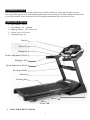
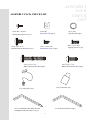
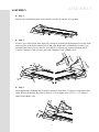
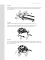
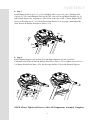
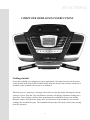
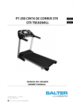
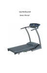
SAFETY HINTS IMPORTANT: THIS UNIT IS INTENDED FOR HOUSEHOLD USE ONLY SAFETY PRECAUTIONS Thank you for purchasing our product. Even though we go to great efforts to ensure the quality of each product, occasional errors and/or omissions do occur. In any event should you find this product to be defective or missing a part please contact our Customer Service Department. Your treadmill was designed and built for optimum safety. However, certain precautions apply whenever you use your treadmill. Be sure to read the manual before assembly and operation. Also, please note the following safety precautions: DANGER: To reduce the risk of electric shock, always unplug the treadmill from the electrical outlet immediately after using and before cleaning. 1. Read OWNER OPERATING MANUAL and all accompanying literature and follow it carefully before using your treadmill. 2. If dizziness, nausea, chest pains, or any other abnormal symptoms are experienced while using this equipment, STOP the workout at once. CONSULT A PHYSICIAN IMMEDIATELY. 3. Never leave the treadmill unattended when plugged in. Unplug from the outlet when not in use and before removing or replacing parts. 4. Never operate the treadmill if it has a damaged cord or plug, if it is not working properly, if it has been dropped, damaged, or exposed to water. 5. Do not pull the treadmill by the power supply cord or use cord as a handle. Keep cord away from heated surfaces and open flames. 6. Fitness equipment must always be installed and used on a flat surface. Do not use outdoors or near water. 7. Do not insert any objects into any openings. 8. Keep children and pets away from this equipment at all times while exercising. 9. Handicapped individuals should have medical approval and close supervision when using this treadmill. 10.Do not place hands or feet under the treadmill. Always keep hands and legs off of the treadmill when others are using it. 11.Never turn on treadmill while standing on treadbelt. Always return the treadmill to slow speed to provide for safe dismount and low speed restart. a-To disconnect, turn all controls to the off position, then remove plug from outlet. b-Use the treadmill only for it is intended use as described in this manual. c-Warm up 5 to 10 minutes before each workout and cool down 5 to 10 minutes afterward. This allows your heart rate to gradually increase and decrease and will help prevent straining muscles. d-Never hold your breath while exercising. Breathing should remain at a normal rate in conjunction with the level of exercise being performed. e-Start your program slowly and very gradually increase your speed and distance. f-Always wear suitable clothing and footwear while exercising. Do not wear loose fitting clothing that could become entangled with the moving parts of your treadmill. g-Do not walk or jog barefoot, in stocking feet or loose fitting shoes or slippers. h-Care must be taken when lifting or moving the equipment, so as not to injure your back. Always use proper lifting techniques. 12. If the supply cord is damaged, it must be replaced by the manufacturer, its service agent or similarly qualified persons in order to avoid a hazard. 13. The appliance is not to be used by children or persons with reduced physical, sensory or mental capabilities, or lack of experience and knowledge, unless they have been given supervision or instruction 14. Children being supervised not to play with the appliance WARNING: Before beginning any exercise program consult your physician. This is especially important for individuals over the age of 35 or persons with pre-existing health problems. Read all instructions before using any fitness equipment. We assume no responsibility from personal injury or property damage sustained by or through the use of this product. CAUTION!! Please be careful when opening this unit. 1 SZ10a-A766CE-1004B INTRODUCTION The treadmill has been designed and constructed to provide trouble free usage and enjoyable exercise. You can greatly improve your understanding and benefits of exercising by carefully reading the instructions given in this manual. Please familiarize yourself with the maintenance advice provided for you. SPECIFICATIONS Drive Motor: 3.0 hp Speed Range: 1.0 – 18 kmph Running Surface: 510 x 1400 m/m Incline Level: 0-15 levels Folding Design: Yes Console Safety Key Handpulse Incline Adjustment Switch Handgrip Tube Speed Adjustment Switch Beverage Holder Handrail Running Belt Wheel Main Frame MAX.USER WEIGHT 130 KGS 2 ASSEMBLY PACK CHECK LIST ASSEMBLY PACK CHECK LIST #140. M5 × 10 m/m Phillips Head Screw (8 pcs) #130. 5/16" ×1/2" Button Head Socket Bolt (8 pcs) #128. M5 Speed Nut Clip (6pcs) #113. Ø10 Split Washer (4pcs) #119. 3.5×12 m/m Sheet Metal Screw (4 pcs) #139. 3/8"× 1-3/4" Button Head Socket Bolt (4pcs) #120. 5 × 16 m/m Tapping Screw (6 pcs) #159. 5/16" × 3/4" Button Head Socket Bolt (4pcs) #134. Lubricant (1pc) #75. Safety Key (1pc) #132. M6 Allen Wrench (1pc) #131. Combination M5 Allen Wrench & Phillips Head Screw Driver (1 pc) 3 ASSEMBLY ASSEMBLY ■ Step 1. Remove the treadmill from the carton and lay it aside on smooth, level ground. ■ Step 2. Locate 6 pcs of M5 Speed Nut Clips(128), which are included in the hardware kit, at the front and each side of the unit as shown below and guide Right and Left Handrails (4) and (5) go through Frame Base Cap (L) and (R), (62) and (63), respectively, as shown further below. Connect Computer Cable (Lower) (49) with Computer Cable (Middle) (50). 62 5 63 4 50 49 ■ Step 3. Insert Right and Left Handrails (4) and (5) into the Frame Base (2) and use Combination M5 Allen Wrench & Phillips Head Screw Driver (131) to tighten 8 pcs of 5/16" × 1/2" Button Head Socket Bolts (130). 4 ASSEMBLY ■ Step 4. Install Frame Base Caps (L and R) (62 and 63) on the Base Frame (2) and secure with 6 pcs of 5 × 16mm Tapping Screws (120) by using Combination M5 Allen Wrench & Phillips Head Screw Driver (131). ■ Step 5. Connect Speed Adjustment Switch W/Cable (54) with Speed Cable (Upper) (37). Connect Incline Adjustment Switch W/Cable (55) with Incline Cable (Upper) (38). Connect Computer Cable (Middle) (50) with Computer Cable (Upper) (48). 37 48 54 50 38 55 ■ Step 6. Insert Console Assembly (52) into Right and Left Handrails (4 and 5) and secure with 4 pcs of 3/8" × 1- 3/4" Button Head Socket Bolts (139) with 4 pcs of Ø10 Split Washers (113) by using M6_Allen Wrench (132). 52 113 132 113 139 139 4 5 5 ASSEMBLY ■ Step 7. Install Handgrip Side Cap (L) (L), (141), Handgrip Side Cap (L) (R), (142), Handgrip Side Cap (R) (L), (143) and Handgrip Side Cap (R) (R), (144) on Left and Right Handrails (4), (5) and Console Support (6), respectively. Then secure with 8 pcs of M5 × 10m/m Phillips Head Screws (140) and 4 pcs of 3.5 ×12m/m Sheet Metal Screws (119) by using Combination M5 Allen Wrench & Phillips Head Screw Driver (131). 119 140 131 140 140 119 140 ■ Step 8. Install Handrail Support (26) between Left and Right Handrails (4) and (5) and use Combination M5 Allen Wrench & Phillips Head Screw Driver (131) to tighten 4 pcs of 5/16" × 3/4" Button Head Socket Bolts (159). Put Beverage Holder (158) on the Handrail Support. 159 159 5 159 4 26 159 158 NOTE: Please Tighten All Screws After All Components Assembly Complete. 6 FUNCTIONS COMPUTER OPERATION INSTRUCTIONS Getting started: Power the treadmill on by plugging it into an appropriate wall outlet, then turn on the power switch located at the front of the treadmill below the motor hood. Ensure that the safety key is installed, as the treadmill will not power on without it. When the power is turned on, a message will scroll across the dot matrix showing the current software version. Then the Time and Distance windows will display Odometer readings for a short time, Time window will show how many hours the treadmill has been in use and the Distance window will show how many miles (or Kilometers if the treadmill is set to metric readings) the treadmill has gone. The treadmill will then enter idle mode, which is the starting point for operation. 7 FUNCTIONS Quick-Start Operation: STEP 1: Attach the Safety key to wake display up (if not already on). STEP 2: Press the Start key to begin belt movement then adjust to the desired speed using the Fast / Slow keys (console or handgrip). You may also use the rapid speed keys 2 through 12 to adjust the speed. STEP 3: To slow tread-belt press and hold the Slow key (console or handgrip) to the desired speed. You may also press the rapid speed adjust keys, 2 through 12. STEP 4: To stop the tread-belt press Stop key or pull away Safety key. Pause/Stop/Reset Feature: STEP 1: When the treadmill is running the pause feature may be utilized by pressing the red Stop key once. This will slowly decelerate the tread-belt to a stop. The incline will go to zero percent. The Time, Distance and Calorie readings will hold while the unit is in the pause mode. After 5 minutes the display will reset and return to the start up screen. STEP 2: To resume your exercise, when in Pause mode, press the Start key. The speed and incline will return to their previous settings. Pause is executed when the Stop button is pressed once. If the Stop key is pressed a second time, the program will end and a workout summary will be displayed. If the Stop button is pressed a third time, the console will return to the idle mode (start up) screen. If the Stop button is held down for more than 3 seconds the console will reset. Incline Feature: Incline may be adjusted anytime after belt movement. Press and hold the Adjust ▲▼ keys (console or handgrip) to achieve desired level of effort. You may also choose a more rapid increase / decrease by selecting desired key, 2 through 12, on left hand side of console (incline). The display will indicate incline position as adjustments are made. Dot Matrix Center Display (Program Operation): Twenty colums of dots (8 high) indicate each segment of a workout. The dots are only to show an approximate level (speed/incline) of effort. They do not necessarily indicate a specific value - only an approximate percent to compare levels of intensity. In operation the Speed / Incline dot matrix window will build a profile “picture” as values are changed during a workout. When the Speed indicator which is above dot matrix is lit the Dot matrix displays the Speed profile and when the Incline indicator is lit the Dot Matrix displays the Incline profile. You may change the Dot Matrix profile view which you desired by pressing the SELECT button. After scrolling through the three profiles which include incline, speed and incline+ speed profile, by pressing the SELECT button, the Dot matrix will automatically scroll through the three displays showing each 8 one for five seconds. FUNCTIONS 0.4km (1/4 mile) Track: The 0.4km (1/4 mile) track will be displayed around the dot matrix window. The flashing dot indicates your progress. Once the 0.4km (1/4 mile) is complete this feature will begin again. The amount of laps are accumulated in the laps window which is below PULSE. Pulse Grip Feature: The Pulse (Heart Rate) console window will display your current heart rate in beats per minute during the workout. You must use both stainless steel sensors on the front cross bar to display your pulse or the wireless chest strap. Pulse value displays anytime the upper display is receiving a Pulse signal. Calorie Display: Displays the cumulative calories burned at any given time during your workout. Note: This is only a rough guide used for comparison of different exercise sessions, which cannot be used for medical purposes. Optional: There is an Audio Input Jack on the front of the console and built-in speakers. You may plug any low-level audio source signal into this port. Audio sources include MP3, Ipod, portable radio, CD player or even a TV or computer audio signal. There is an audio patch cable included to and also a headphone jack for private listening. To Turn Treadmill Off (Blank out Display): Two methods accomplish this: Use either one. (1) Display will automatically turn off (blank out) after 10 minutes (no key operations) in Pause / Stop mode. (2) Remove safety key. Programmable Features Factory preset programs, 2 user defined programs, one Manual program (P0) and P1-P5 programs. Each preset program has a maximum speed level that is displayed when a desired workout is chosen. The maximum speed that the particular program will achieve will be displayed in the Speed window. Also included are two user programs (User 1 and User 2) for custom workouts. To Select a Program: STEP 1: Press the PROGRAM ▲▼ key to select desired program which include Manual (P0) and P1P5. Press enter to select the program. The display will prompt you through the programming or you can just press Start to begin the program with default values. STEP 2: If enter was pressed, the Time window will display with the default value of 20 minutes. You may use any of the up/down, fast/slow keys to adjust the time. After adjusting, or to accept the default value, press enter. (Note: You may press start at any time during the programming to start the program.) 9 FUNCTIONS STEP 3: The Calorie window will now be displaying a value, which is your Body Weight. Entering the correct body weight will affect the calorie count. Use the Up/Down keys, Fast/Slow to adjust, then press enter. A note about the Calorie display: No exercise machine can give you an exact calorie count because there are too many factors which determine exact calorie burn for a particular person. Even if someone is the exact same body weight, age and height, their calorie burn may be very different than yours. The Calorie display is to be used as a reference only to monitor improvement from workout to workout. STEP 4: The Calorie window will display the preset top speed of the selected program. Use the Up/Down, Fast/Slow keys to adjust, and then press enter. Each program has various speed changes through out, this allows you to limit the highest speed the program can reach. User Programs: STEP 1: Select User 1 or User 2 via the PROGRAM key then press Enter. Note that the dot matrix display portion will have a single row of dots at the bottom (Unless there is a previously stored program). STEP 2: Note the Time window is flashing. Use the Adjust ▲▼ keys to adjust up from 10 minutes (if desired). Press ENTER key. This is a must to continue even if time is not adjusted. STEP 3: The Calorie window will now be blinking a bodyweight value. Enter your bodyweight and press Enter. STEP 4: The first column (segment) will now be blinking. Using the Fast / Slow or rapid keys, adjust the speed level to your desired effort for the first segment then press enter. The second column will now be blinking. Repeat the above process until all segments have been programmed. The first column will be blinking again. This is for the incline programming. Repeat the above process to program all segments for incline. STEP 5: Press the Start button to begin the workout and also save the program to memory.] LUBE INDICATOR: Every 180 hours or 1000km of use apply one half bottle of lubricant per exact situation between running belt and running board. ERROR MESSAGE: 1. LS: Treadmill doesn’t receive the speed signal for 8 seconds. 2. E1: Memory of console malfunction or CPU accessing problem. 3. E2: Incline position error. 10 FUNCTIONS Program P1 SPEED PROGRAM P1 INCLINE PROGRAM P2 SPEED PROGRAM P2 INCLINE PROGRAM P3 SPEED PROGRAM P3 INCLINE PROGRAM P4 SPEED PROGRAM P4 INCLINE PROGRAM P5 SPEED PROGRAM P5 INCLINE PROGRAM 11 UNFOLDING FOLDING TRANSPORT Do not attempt to move the unit unless it is in the folded and locked position. Be sure the power cord is secured to avoid possible damage. Use both handrails to maneuver the unit to the desired position. ■ Unfoldong The Treadmill: Apply slight forward pressure* on the treadmill running deck with one hand. Pull down on the unlocking lever and slowly lower the running deck to the floor. The deck will lower unassisted when it reaches about waist high. (As shown Figure 1.) *At the rear roller area to relieve pressure on the locking system. ■ Folding The Treadmill: Make certain the treadmill is at minimum incline. Lift the treadmill running deck until it is secured by the locking telescoping tube assembly in center back of base. (As shown Figure 2&3.) ■Transport The treadmill is equipped with four transport wheels which are engaged when the treadmill is folded. After folding simply roll the treadmill away. (As shown Figure 4.) 12 BELT TRACKING ADJUSTMEANT If during use you notice that walking belt either shifts to the right or the left of center, first remove "Safety Key" and unplug equipment from AC power source. Using M6 Allen wrench provided, turn left rear roller adjustment as indicated below clockwise no more the 1/4" of a turn. Remove M6 Allen wrench, insert "Safety Key" and insert AC power cord into AC outlet. Turn on your treadmill and observe after running a few minutes to see if problem has been corrected. This may take several adjustments, so repeat the above procedure. 13 TREADMILL LUBRICATION Your treadmill should require little maintenance other then periodically applying lubricant. Lubricating under the treadbelt will ensure superior performance and extend its life expectancy. HOW TO CHECK TREADBELT FOR PROPER LUBRICATION? Lift one side of the treadbelt and feel the top surface of the treadboard. If the surface is slick to the touch, then no further lubrication is required. If the surface is dry to the touch, apply one packet of lubricant or half of the bottle of lubricant. HOW TO APPLY LUBRICANT? 1. Lift one side of treadbelt. 2. Pour one half of the lubricant bottle under the center of the treadbelt on the top surface of the treadboard. 3. Walk on the treadmill at a slow speed for 3 to 5 minutes to evenly distribute lubricant. NOTE: DO NOT over lubricate treadboard. Any excess lubricant that comes out should be wiped off. IMPORTANT: ONLY USE HALF THE BOTTLE OF LUBRICANT PER APPLICATION LUBRICATION SCHEDULE. 1. If it’s necessary, it’s better to lubricate half a bottle when user open carton to use at first time. 2. We suggest if user doesn’t apply lubricant at first time, after the first 25 hours of use (2-3 months ) need to apply one half bottle of lubricant. 3. Every 180 hours or 1000km of use apply one half bottle of lubricant per exact situation. 14 AEROBIC EXERCISE Aerobic exercise is any sustained activity that sends oxygen to your muscles via your heart and lungs. Aerobic exercise improves the fitness of your lungs and heart - your body’s most important muscle. Aerobic exercise fitness is promoted by any activity that uses your large muscle -arms, legs, or buttock, for example. Your heart beats quickly and you breathe deeply. An aerobic exercise should be part of your entire exercise routine. WEIGHT TRAINING Along with aerobic exercising which helps get rid of and keep off the excess fat that our bodies can store, weight training is an essential part of the exercise routine process. Weight training helps tone, build and strengthen muscle. If you are working above your target zone, you may want to do a less amount of reps. And as always ,consult your physician before beginning any exercise program. MUSCLE CHART CYCLE The exercise routine that is performed on the cycle will develop the lower body muscle group as well as condition the circulatory system and provide a good aerobic workout . These muscle groups are highlighted on the muscle chart below. 15 WARM UP Quadriceps Stretch With one hand against a wall for balance, reach behind you and pull your right foot up. Bring your heel as close to your buttocks as possible. Hold for 15 counts and repeat with left foot up. Inner Thigh Stretch Sit with the soles of your feet together with your knees pointing outward. Pull your feet as close into your groin as possible. Gently push your knees towards the floor. Hold for 10 counts Toe Touches Slowly bend forward from your waist, letting you back and shoulders relax as you stretch toward your toes. Reach down as far as you can and hold for 15 counts. Hamstring Stretches Sit with your right leg extended. Rest the sole of your left foot against your right inner thigh. Stretch toward your toe as far as possible. Hold for 15 counts Relax and then repeat with left leg extended. 16 OVERVIEW CHART 17 NO. 1 2 3 4 5 6 7 8 9 10 11 12 13 14 15 16 17 18 19 20 21 21~2 22 23 24 25 26 27 28 29 30 31 32 34 35 36 37 38 39 39~2 39~3 39~4 39~5 40 41 42 43 44 45 46 47 48 49 50 51 52 DESCRIPTION Main Frame Frame Base Incline Bracket Right Upright Left Upright Console Support Deck Cross Brace Outer Slide Inner Slide Link Link Shaft Shaft Bushing Fastening Bracket Clevis Pin Fastening Bushing Dual Torsion-Spring Release Lever ChenChin Torsion-Spring Cylinder Drive Belt Front Roller W/Pulley Magnet Rear Roller Running Deck Running Belt PVC Handgrip Handdrail Support Steel Rope Tension Wire Clamp Wire Tie Mount Bottom Frame Cover Steel Cable Top Frame Cover Motor Incline Motor Controller 800m/m_Speed Cable (Upper) 800m/m_Incline Cable (Upper) Handpulse Assembly 650m/m_Handpulse Wire, Coiled Handpulse Top Cover Handpulse Bottom Cover Handpulse End Cap 1200m/m_Sensor W/Cable Breaker Power Socket On/Off Switch Power Cord 100m/m_Connecting Wire (Black) 300m/m_Connecting Wire (White) 300m/m_Connecting Wire (Black) 800m/m_Computer Cable (Upper) 1150m/m_Computer Cable (Lower) 1100m/m_Computer Cable (Middle) Sensor Rack Console Assembly 18 PARTS LIST O'TY 1 1 1 1 1 1 1 1 1 1 1 2 2 1 1 1 1 1 1 1 1 2 1 1 1 2 1 1 1 8 1 1 1 1 1 1 1 1 2 1 2 2 2 1 1 1 1 1 1 1 1 1 1 1 1 1 NO. 52~1 52~2 52~5 52~6 52~14 52~15 52~16 52~17 52~18 52~19 52~20 52~21 52~22 52~25 52~27 52~28 52~30 52~31 52~32 52~33 53 54 55 56 57 58 59 60 61 62 63 64 65 66 67 68 69 70 71 72 73 74 75 76 77 80 81 82 83 84 85 86 87 88 89 90 DESCRIPTION Console Top Cover Console Bottom Cover Drink Bottle Holder (L) Drink Bottle Holder (R) Front Console Cover (Top) Front Console Cover (Bottom) 300m/m_Safety Switch Module W/ Cable Fan Deflector Fan Grill Fan Grill Anchor 700m/m_Speaker W/Cable 250m/m_Speaker W/Cable Amplifier Controller Receiver, HR Assembly Speaker Iron Net (L) Speaker Iron Net (R) Badge 400m/m_Amplifier Cable 3 × 10m/m_Sheet Metal Screw 400m/m_Console Ground Wire Motor Top Cover 300m/m_Speed Adjustment Switch W/Cable 300m/m_Incline Adjustment Switch W/Cable Cushion Ø75 ×35L_Transportation Wheel(A) Ø62 × Ø32 × 30L_Transportation Wheel(B) Square End Cap 300m/m_Foot Rail 615m/m_Foot Rail Frame Base Cover (L) Frame Base Cover (R) Left Connecting Cap (Top) Left Connecting Cap (Bottom) Right Connecting Cap (Top) Right Connecting Cap (Bottom) Rear Adjustment Base (L) Rear Adjustment Base (R ) Motor Cover Anchor(D) Ø10 × Ø24 × 3T_Nylon Washer (A) Ø50 × Ø13 × 3T_Nylon Washer (B) Adjustment Foot Pad Motor Bracket Ellipse Safety Key Belt Guide Sleeve for Frame Base Front Wheel 1/2" × 1-1/4"_Carriage Bolt 1/2" × 1" _Hex Head Bolt 3/8" × 4-1/2"_Socket Head Cap Bolt(Alloy Steel) 3/8" × 3-3/4"_Hex Head Bolt 3/8" × 1-1/2"_Hex Head Bolt 3/8" × 3/4"_Hex Head Bolt 3/8" × 2"_Thumb Head Socket Bolt 5/16" × 1"_Button Head Socket Bolt 5/16" × 2-3/4"_Button Head Socket Bolt M8 × 60m/m_Hex Head Bolt M8 × 80m/m_Socket Head Cap Bolt 19 PARTS LIST O'TY 1 1 1 1 1 1 1 1 2 4 1 1 1 1 1 1 1 1 2 1 1 1 1 6 2 2 2 2 2 1 1 1 1 1 1 1 1 5 2 4 2 1 1 2 2 2 2 1 1 1 4 2 2 2 1 2 NO. 91 92 93 94 95 96 97 98 99 100 101 102 103 104 105 106 107 108 109 110 111 112 113 114 115 116 117 118 119 120 121 124 125 126 127 128 129 130 131 132 133 134 136 137 139 140 141 142 143 144 145 146 147 148 149 150 DESCRIPTION M8 × 50m/m_Flat Head Countersink Bolt M8 × 25m/m_Flat Head Countersink Bolt M3 × 10m/m_Phillips Head Screw M5 × 20m/m_Phillips Head Screw M8 × 12m/m_Hex Head Bolt 5/16" × 42 m/m_Button Head Socket Bolt M5_Nyloc Nut 1/2"_Nyloc Nut 3/8"_Nyloc Nut 5/16"_Nyloc Nut M8_Nyloc Nut 3/8"_Nut M3_Nut Ø35 × Ø5/16" × 1.5T_Flat Washer Ø25 × Ø10 × 1.5T_Flat Washer Ø19 × Ø10 × 1.5T_Flat Washer Ø5 × Ø10 × 1.0T_Flat Washer Ø5/16" × Ø18 × 1.5T_Flat Washer Ø5 × Ø13 × 1.0T_Flat Washer Ø1/4" × 19 × 1.5T_Flat Washer Ø6.5 × Ø25 × 1.5T_Concave Washer M8_Split Washer Ø10_Split Washer M3_Split Washer M5_Star Washer 4 × 12m/m_Sheet Metal Screw 5 × 16m/m_Tapping Screw 5 × 19m/m_Tapping Screw 3.5 × 12m/m_Sheet Metal Screw 5 × 16m/m_Tapping Screw Ø13 × Ø32 × 2.5T_Flat Washer 3 × 12 m/m_Tapping Screw 4 × 50m/m_Sheet Metal Screw 3.5 × 16 m/m_Tapping Screw 3 × 10 m/m_Sheet Metal Screw M5_Speed Nut 3 × 8m/m_Sheet Metal Screw 5/16" × 1/2"_Button Head Socket Bolt Combination M5 Allen Wrench & Phillips Head Screw Driver M6_Allen Wrench Controller Back Plate Lubricant Oval End Cap 3.5 × 32m/m_Sheet Metal Screw 3/8" × 1-3/4"_Button Head Socket Bolt M5 × 10m/m_Phillips Head Screw Left Handgrip Side Cap (L) Left Handgrip Side Cap(R) Right Handgrip Side Cap(L) Right Handgrip Side Cap (R) Cushion Spacer(L) Cushion Spacer(R) Top Motor Cover Plate Pedal Cover Pedal Cover(Inner) Chest Strap 20 PARTS LIST O'TY 2 6 1 1 2 1 1 4 4 3 1 3 1 2 4 4 2 1 1 2 8 2 8 1 4 20 46 1 35 13 2 4 2 8 2 6 6 8 1 1 1 1 2 8 4 12 1 1 1 1 1 1 1 2 16 1 NO. 151 152 153 154 157 158 159 160 161 162 163 164 DESCRIPTION 1000m/m_Ground Wire 13m/m_Bolt Cap 400m/m_Audio Cable Plastic Washer 3.5 × 18m/m_Sheet Metal Screw Beverage Holder 5/16" × 3/4"_Button Head Socket Bolt M5_Split Washer Filter 240m/m_Choke 600m/m_Connecting Cable Of Motor 200m/m × 764 × 764_Connecting Wire (White) 21 PARTS LIST O'TY 1 2 1 4 6 1 4 4 1 1 1 1