1
BreezeCOMPACT
System Manual
Release Version:1.0
May 2012
P/N 216013
Document History
Document History
Topic
Description
Date Issued
BreezeCOMPACT System Manual
First publication of a System Manual for
a new product
May 2012
BreezeCOMPACT System Manual
ii
Legal Rights
Legal Rights
© Copyright 2012 Alvarion Ltd. All rights reserved.
The material contained herein is proprietary, privileged, and confidential and owned by Alvarion or its
third party licensors. No disclosure thereof shall be made to third parties without the express written
permission of Alvarion Ltd.
Alvarion Ltd. reserves the right to alter the equipment specifications and descriptions in this publication
without prior notice. No part of this publication shall be deemed to be part of any contract or warranty
unless specifically incorporated by reference into such contract or warranty.
Trade Names
Alvarion®, BreezeCOM®, WALKair®, WALKnet®, BreezeNET®, BreezeACCESS®, BreezeLINK®,
BreezeMAX®, BreezeLITE®, BreezePHONE®, 4Motion®, and/or other products and/or services referenced
here in are either registered trademarks, trademarks or service marks of Alvarion Ltd.
All other names are or may be the trademarks of their respective owners.
“WiMAX Forum” is a registered trademark of the WiMAX Forum. “WiMAX,” the WiMAX Forum logo,
“WiMAX Forum Certified”, and the WiMAX Forum Certified logo are trademarks of the WiMAX Forum.
Statement of Conditions
The information contained in this manual is subject to change without notice. Alvarion Ltd. shall not be
liable for errors contained herein or for incidental or consequential damages in connection with the
furnishing, performance, or use of this manual or equipment supplied with it.
Warranties and Disclaimers
All Alvarion Ltd. (“Alvarion“) products purchased from Alvarion or through any of Alvarion's authorized
resellers are subject to the following warranty and product liability terms and conditions.
Exclusive Warranty
(a) Alvarion warrants that the Product hardware it supplies and the tangible media on which any
software is installed, under normal use and conditions, will be free from significant defects in materials
and workmanship for a period of fourteen (14) months from the date of shipment of a given Product to
Purchaser (the "Warranty Period"). Alvarion will, at its sole option and as Purchaser's sole remedy, repair
or replace any defective Product in accordance with Alvarion' standard R&R procedure.
(b) With respect to the Firmware, Alvarion warrants the correct functionality according to the attached
documentation, for a period of fourteen (14) month from invoice date (the "Warranty Period")". During
the Warranty Period, Alvarion may release to its Customers firmware updates, which include additional
performance improvements and/or bug fixes, upon availability (the "Warranty"). Bug fixes, temporary
patches and/or workarounds may be supplied as Firmware updates.
Additional hardware, if required, to install or use Firmware updates must be purchased by the Customer.
Alvarion will be obligated to support solely the two (2) most recent Software major releases.
ALVARION SHALL NOT BE LIABLE UNDER THIS WARRANTY IF ITS TESTING AND EXAMINATION DISCLOSE
THAT THE ALLEGED DEFECT IN THE PRODUCT DOES NOT EXIST OR WAS CAUSED BY PURCHASER'S OR
ANY THIRD PERSON'S MISUSE, NEGLIGENCE, IMPROPER INSTALLATION OR IMPROPER TESTING,
UNAUTHORIZED ATTEMPTS TO REPAIR, OR ANY OTHER CAUSE BEYOND THE RANGE OF THE INTENDED
USE, OR BY ACCIDENT, FIRE, LIGHTNING OR OTHER HAZARD.
BreezeCOMPACT System Manual
i
Legal Rights
Disclaimer
(a) The Software is sold on an "AS IS" basis. Alvarion, its affiliates or its licensors MAKE NO
WARRANTIES, WHATSOEVER, WHETHER EXPRESS OR IMPLIED, WITH RESPECT TO THE SOFTWARE AND
THE ACCOMPANYING DOCUMENTATION. ALVARION SPECIFICALLY DISCLAIMS ALL IMPLIED
WARRANTIES OF MERCHANTABILITY AND FITNESS FOR A PARTICULAR PURPOSE AND
NON-INFRINGEMENT WITH RESPECT TO THE SOFTWARE. UNITS OF PRODUCT (INCLUDING ALL THE
SOFTWARE) DELIVERED TO PURCHASER HEREUNDER ARE NOT FAULT-TOLERANT AND ARE NOT
DESIGNED, MANUFACTURED OR INTENDED FOR USE OR RESALE IN APPLICATIONS WHERE THE
FAILURE, MALFUNCTION OR INACCURACY OF PRODUCTS CARRIES A RISK OF DEATH OR BODILY
INJURY OR SEVERE PHYSICAL OR ENVIRONMENTAL DAMAGE ("HIGH RISK ACTIVITIES"). HIGH RISK
ACTIVITIES MAY INCLUDE, BUT ARE NOT LIMITED TO, USE AS PART OF ON-LINE CONTROL SYSTEMS IN
HAZARDOUS ENVIRONMENTS REQUIRING FAIL-SAFE PERFORMANCE, SUCH AS IN THE OPERATION OF
NUCLEAR FACILITIES, AIRCRAFT NAVIGATION OR COMMUNICATION SYSTEMS, AIR TRAFFIC CONTROL,
LIFE SUPPORT MACHINES, WEAPONS SYSTEMS OR OTHER APPLICATIONS REPRESENTING A SIMILAR
DEGREE OF POTENTIAL HAZARD. ALVARION SPECIFICALLY DISCLAIMS ANY EXPRESS OR IMPLIED
WARRANTY OF FITNESS FOR HIGH RISK ACTIVITIES.
(b) PURCHASER'S SOLE REMEDY FOR BREACH OF THE EXPRESS WARRANTIES ABOVE SHALL BE
REPLACEMENT OR REFUND OF THE PURCHASE PRICE AS SPECIFIED ABOVE, AT ALVARION'S OPTION.
TO THE FULLEST EXTENT ALLOWED BY LAW, THE WARRANTIES AND REMEDIES SET FORTH IN THIS
AGREEMENT ARE EXCLUSIVE AND IN LIEU OF ALL OTHER WARRANTIES OR CONDITIONS, EXPRESS OR
IMPLIED, EITHER IN FACT OR BY OPERATION OF LAW, STATUTORY OR OTHERWISE, INCLUDING BUT
NOT LIMITED TO WARRANTIES, TERMS OR CONDITIONS OF MERCHANTABILITY, FITNESS FOR A
PARTICULAR PURPOSE, SATISFACTORY QUALITY, CORRESPONDENCE WITH DESCRIPTION,
NON-INFRINGEMENT, AND ACCURACY OF INFORMATION GENERATED. ALL OF WHICH ARE EXPRESSLY
DISCLAIMED. ALVARION' WARRANTIES HEREIN RUN ONLY TO PURCHASER, AND ARE NOT EXTENDED
TO ANY THIRD PARTIES. ALVARION NEITHER ASSUMES NOR AUTHORIZES ANY OTHER PERSON TO
ASSUME FOR IT ANY OTHER LIABILITY IN CONNECTION WITH THE SALE, INSTALLATION, MAINTENANCE
OR USE OF ITS PRODUCTS.
Limitation of Liability
(a) ALVARION SHALL NOT BE LIABLE TO THE PURCHASER OR TO ANY THIRD PARTY, FOR ANY LOSS OF
PROFITS, LOSS OF USE, INTERRUPTION OF BUSINESS OR FOR ANY INDIRECT, SPECIAL, INCIDENTAL,
PUNITIVE OR CONSEQUENTIAL DAMAGES OF ANY KIND, WHETHER ARISING UNDER BREACH OF
CONTRACT, TORT (INCLUDING NEGLIGENCE), STRICT LIABILITY OR OTHERWISE AND WHETHER BASED
ON THIS AGREEMENT OR OTHERWISE, EVEN IF ADVISED OF THE POSSIBILITY OF SUCH DAMAGES.
(b) TO THE EXTENT PERMITTED BY APPLICABLE LAW, IN NO EVENT SHALL THE LIABILITY FOR DAMAGES
HEREUNDER OF ALVARION OR ITS EMPLOYEES OR AGENTS EXCEED THE PURCHASE PRICE PAID FOR
THE PRODUCT BY PURCHASER, NOR SHALL THE AGGREGATE LIABILITY FOR DAMAGES TO ALL PARTIES
REGARDING ANY PRODUCT EXCEED THE PURCHASE PRICE PAID FOR THAT PRODUCT BY THAT PARTY
(EXCEPT IN THE CASE OF A BREACH OF A PARTY'S CONFIDENTIALITY OBLIGATIONS).
Radio Frequency Interference Statement
The Base Transceiver Station (BTS) equipment has been tested and found to comply with the limits for a
class A digital device, pursuant to ETSI EN 301 489-1 rules and Part 15 of the FCC Rules. These limits are
designed to provide reasonable protection against harmful interference when the equipment is operated
in commercial, business and industrial environments. This equipment generates, uses, and can radiate
radio frequency energy and, if not installed and used in accordance with the instruction manual, may
cause harmful interference to radio communications. Operation of this equipment in a residential area is
likely to cause harmful interference in which case the user will be required to correct the interference at
the user's own expense.
BreezeCOMPACT System Manual
ii
Legal Rights
FCC and Industry Canada Radiation Hazard Warning
To comply with Industry Canada exposure requirements, and FCC RF exposure requirements in Section
1.1307 and 2.1091 of FCC Rules, the antenna used for this transmitter must be fixed-mounted on
outdoor permanent structures with a separation distance of at least 205 cm from all persons.
Industry Canada Statement
Users can obtain Canadian information on RF exposure and compliance from the Canadian
Representative:
Nick Dewar
[email protected]
Canadian Radio Standards Specifications (RSS) Compliance Statement
This device has been designed to operate with the antennas listed in Section 1.4.8, and having a
maximum gain of 18 dBi. Antennas not included in this list or having a gain greater than 18 dBi are
strictly prohibited for use with this device.
To reduce potential radio interference to other users, the antenna type and its gain should be so chosen
that the Equivalent Isotropically Radiated Power (EIRP) is not more than that permitted for successful
communication.
R&TTE Compliance Statement
This equipment complies with the appropriate essential requirements of Article 3 of the R&TTE Directive
1999/5/EC.
Safety Considerations - General
For the following safety considerations, “Instrument” means the BreezeCOMPACT units' components
and their cables.
Grounding
BTS chassis is required to be bonded to protective grounding using the bonding stud or screw provided
with each unit.
Safety Considerations - DC Powered Equipment
CAUTION
ATTENTION
Risk of electric shock and energy hazard.
Risque de décharge électrique et d'electrocution.
Restricted Access Area: The DC powered
equipment should only be installed in a Restricted
Access Area.
Zone d’Accès Limité: L’alimentation en courant
continue doit être installée dans une zone a accès
limité
Installation Codes: The equipment must be
installed according to the latest edition of the
country national electrical codes. For North
America, equipment must be installed in
accordance with the US National Electrical Code
and the Canadian Electrical Code.
Normes d’installation: les équipements doivent
être installes d’après les dernières normes en
vigueur. Pour l’Amérique du nord les équipements
doivent être installés d’après les normes
électriques nationales US et les normes électriques
Canadiennes.
BreezeCOMPACT System Manual
iii
Legal Rights
Overcurrent Protection: A readily accessible
Listed branch circuit overcurrent protective device,
rated 10A must be incorporated in the building
wiring.
Protection de surintensité: Une protection de
surintensité de 10A doit être installée sur le circuit
d’alimentation.
CAUTION: This equipment is designed to permit
connection between the earthed conductor of the
DC supply circuit and the grounding conductor at
the equipment. See installation instructions.
ATTENTION: Cet équipement est prévu pour
permettre une mise a la terre entre le courant
continu et le reste de l’installation. Voir les
instructions d’installation.
The equipment must be connected directly to the
L’appareil doit être connecté a la terre de
DC Supply System grounding electrode conductor.
All equipment in the immediate vicinity must be
grounded in the same way, and not be grounded
elsewhere.
The DC supply system is to be local, i.e. within the
same premises as the equipment.
l’allimentation en courant continu.
Tout appareil dans la proximité immédiate doit être
connecté a la terre de la même manière et pas
autrement.
L’alimentation du système en courant continu doit
être local et remplir les mêmes conditions que le
matériel.
There shall be no disconnect device between the
grounded circuit conductor of the DC source (return)
and the point of connection of the grounding
electrode conductor.
Le circuit de terre doit être ininterrompu entre la
source et les différents appareils
Caution
To avoid electrical shock, do not perform any servicing unless you are qualified to do so.
Pour éviter tout choque électrique ne pas intervenir sur les circuits électriques si vous n’êtes pas qualifié
pour
Line Voltage
Before connecting this instrument to the power line, make sure that the voltage of the power source
matches the requirements of the instrument.
Laser
CLASS 1 LASER PRODUCT
APPAREIL A` LASER DE CLASSE 1
The system can be equipped with Class 1
laser products, which comply with IEC
60825-1, IEC 60825-2 and UL recognized
laser or CDRH CFR Title 21, part 1040.
Classe du Laser
The system does not emit hazardous light,
and the beam is totally enclosed during
normal operation, as long as the
equipment is operated in accordance with
the applicable safety instructions
BreezeCOMPACT System Manual
Le système peut être équipe d’un laser de classe 1 selon la
norme IEC 60825-1, IEC 60825-2 et reconnu comme UL laser
ou CDRH CFR titre 21 ,partie 1040.
Le système n’émet pas de lumière apparente et le rayon est
entièrement protégé pendant l’utilisation normal du système par
l’utilisateur tant que les appareils sont utilisés en suivant les
instructions de sécurité.
iv
Legal Rights
Laser Safety Statutory Warning
All personnel involved in equipment installation, operation, and maintenance must be aware that laser
radiation is invisible. Therefore, although protective devices generally prevent directly exposure to the
beam, personnel must strictly observe the applicable safety precautions, and in particular, must avoid
staring into optical connectors, either directly or using optical instruments.
Remember that observing safety precautions is not a matter of personal choice; ignoring safety puts all
people within the line-of-sight in danger.
Précautions de sécurité réglementaire pour laser
Tout personnel impliqué dans l’installation, le fonctionnement et la maintenance de l’installation
doivent savoir que les radiations laser sont invisibles . Donc , bien que généralement les protections
évitent tout contact direct avec les rayons émis, le personnel doit observer strictement les précautions
de sécurité et en particulier , les connecteurs optiques , aussi bien directement ou avec des instruments
d’optique.
Souvenez vous que remplir les précautions de sécurité n’est en aucun cas un choix personnel; ignorer les
règles de sécurité mets toutes les personnes en présence en danger.
Radio
The instrument transmits radio energy during normal operation. To avoid possible harmful exposure to
this energy, do not stand or work for extended periods of time in front of its antenna. The long-term
characteristics or the possible physiological effects of radio frequency electromagnetic fields have not
been yet fully investigated.
Outdoor Units and Antennas Installation and Grounding
Ensure that outdoor units, antennas and supporting structures are properly installed to eliminate any
physical hazard to either people or property. Make sure that the installation of the outdoor unit, antenna
and cables is performed in accordance with all relevant national and local building and safety codes.
Even where grounding is not mandatory according to applicable regulation and national codes, it is
highly recommended to ensure that the outdoor unit and the antenna mast are grounded and suitable
lightning protection devices are used so as to provide protection against voltage surges and static
charges. In any event, Alvarion is not liable for any injury, damage or regulation violations associated
with or caused by installation, grounding or lightning protection.
Disposal of Electronic and Electrical Waste
Disposal of Electronic and Electrical Waste
Pursuant to the WEEE EU Directive electronic and electrical waste must not be disposed of with unsorted waste.
Please contact your local recycling authority for disposal of this product.
BreezeCOMPACT System Manual
v
Important Notice
Important Notice
This user manual is delivered subject to the following conditions and restrictions:
This manual contains proprietary information belonging to Alvarion Ltd. Such information is supplied
solely for the purpose of assisting properly authorized users of the respective Alvarion products.
No part of its contents may be used for any other purpose, disclosed to any person or firm or
reproduced by any means, electronic and mechanical, without the express prior written permission of
Alvarion Ltd.
The text and graphics are for the purpose of illustration and reference only. The specifications on
which they are based are subject to change without notice.
The software described in this document is furnished under a license. The software may be used or
copied only in accordance with the terms of that license.
Information in this document is subject to change without notice. Corporate and individual names
and data used in examples herein are fictitious unless otherwise noted.
Alvarion reserves the right to alter the equipment specifications and descriptions in this publication
without prior notice. No part of this publication shall be deemed to be part of any contract or
warranty unless specifically incorporated by reference into such contract or warranty.
The information contained herein is merely descriptive in nature, and does not constitute an offer for
the sale of the product described herein.
Any changes or modifications of equipment, including opening of the equipment not expressly
approved by Alvarion Ltd. will void equipment warranty and any repair thereafter shall be charged for.
It could also void the user's authority to operate the equipment.
Some of the equipment provided by Alvarion and specified in this manual, is manufactured and
warranted by third parties. All such equipment must be installed and handled in full compliance with the
instructions provided by such manufacturers as attached to this manual or provided thereafter by
Alvarion or the manufacturers. Non-compliance with such instructions may result in serious damage
and/or bodily harm and/or void the user's authority to operate the equipment and/or revoke the
warranty provided by such manufacturer.
BreezeCOMPACT System Manual
vi
About This Manual
About This Manual
This manual describes the BreezeCOMPACT solution, and details how to install, operate and manage the
BTS equipment.
This manual is intended for technicians responsible for installing, setting and operating the
BreezeCOMPACT BTS equipment, and for system administrators responsible for managing the system.
This manual contains the following chapters and appendices:
Chapter 1 - System description: Describes the BreezeCOMPACT system.
Chapter 2 - Installation: Describes how to install the BTS equipment.
Chapter 3 - Commissioning: Describes how to configure basic parameters and validate units'
operation.
Chapter 4 - Operation and Administration: Describes how to use the Monitor program for
configuring parameters, checking system status and monitoring performance.
BreezeCOMPACT System Manual
i
Contents
Contents
Chapter 1 - System Description ............................................................................. 1
1.1 About WiMAX .......................................................................................................2
1.1.1 Introduction to WiMAX ......................................................................................... 2
1.1.2 WiMAX Network Reference Model ........................................................................ 2
1.2 The BreezeCOMPACT Solution...............................................................................9
1.2.1 BreezeCOMPACT Highlights................................................................................... 9
1.2.2 Network Architectures.......................................................................................... 9
1.2.3 System Topologies.............................................................................................. 10
1.2.4 Antennas ............................................................................................................ 12
1.2.5 GPS...................................................................................................................... 12
1.3 Element Management Systems ...........................................................................13
1.3.1 AlvariSTAR........................................................................................................... 13
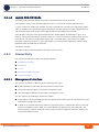
1.4 Specifications ....................................................................................................14
1.4.1 Modem & Radio .................................................................................................. 14
1.4.2 Sensitivity (per channel)* ................................................................................... 15
1.4.3 Data Communication (Ethernet Interfaces) ........................................................ 15
1.4.4 Configuration and Management ......................................................................... 16
1.4.5 Standards Compliance, General .......................................................................... 16
1.4.6 Environmental..................................................................................................... 16
1.4.7 Mechanical and Electrical .................................................................................... 17
1.4.8 Antennas ............................................................................................................ 18
1.4.9 BMAX-4M-GPS Receiver Specifications ............................................................... 25
Chapter 2 - BreezeCOMPACT Installation.............................................................. 26
2.1 Introduction.......................................................................................................27
2.2 Unpacking and Inspecting ...................................................................................28
2.2.1 Package Content................................................................................................. 29
2.2.2 Additional Installation Requirements.................................................................. 29
2.2.3 Mounting Options ............................................................................................... 30
2.3 BreezeCOMPACT Installation...............................................................................33
BreezeCOMPACT System Manual
ii
Contents
2.3.1 Installing the BTS on a Pole ................................................................................ 33
2.4 Pole Mounting without an Attached Antenna (Standalone) .................................34
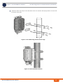
2.5 Pole Mounting with an Attached Antenna ...........................................................38
2.5.1 Package Content................................................................................................. 38
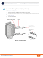
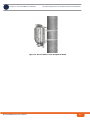
2.5.2 Mounting the BTS and Antenna on the Carriage ................................................ 39
2.5.3 Wall Mount Installation ....................................................................................... 44
2.6 GPS Installation..................................................................................................46
2.6.1 Package Content................................................................................................. 46
2.6.2 Additional Installation Requirements.................................................................. 46
2.6.3 Installing the GPS ................................................................................................ 46
2.6.4 Connecting the GPS ............................................................................................ 49
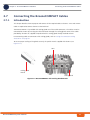
2.7 Connecting the BreezeCOMPACT Cables ..............................................................52
2.7.1 Introduction ........................................................................................................ 52
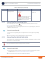
2.7.2 Connecting the Grounding Cable ........................................................................ 55
2.7.3 Connecting the Optical Data Cable ..................................................................... 55
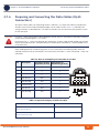
2.7.4 Preparing and Connecting the Data Cables (RJ-45 Connectors) ......................... 56
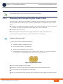
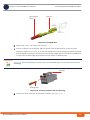
2.7.5 Preparing and Connecting the Power Cable........................................................ 58
2.7.6 Connecting the GPS Cable................................................................................... 61
2.7.7 Using the Connector Sealing Accessories ........................................................... 61
2.7.8 Connecting to Antennas ..................................................................................... 64
2.8 System Initial Verification ..................................................................................65
Chapter 3 - Commissioning .................................................................................. 66
3.1 Introduction.......................................................................................................67
3.2 Configuring Parameters Required for Management Connectivity..........................68
3.2.1 Configuring the BTS Number............................................................................... 68
3.2.2 Configuring the Management Interface Connectivity Mode Parameter .............. 68
3.2.3 Configuring the IP Interfaces Parameters ........................................................... 68
3.2.4 Configuring the L1 and L2 Parameters (if necessary)......................................... 69
3.2.5 Configuring the SNMP Authorized Manager and Traps Manager ........................ 70
3.2.6 Applying the Configuration ................................................................................. 70
3.3 Activating the Unit .............................................................................................72
3.3.1 Creating the BS ................................................................................................... 72
3.3.2 Defining the Antenna(s) ..................................................................................... 74
3.3.3 Configuring Radio Cluster Parameters ................................................................ 74
BreezeCOMPACT System Manual
iii
Contents
3.3.4 Configuring Antenna Associations ...................................................................... 75
3.3.5 Applying the Configuration ................................................................................. 75
Chapter 4 - Operation and Administration .......................................................... 76
4.1 BTS System Management ...................................................................................77
4.2 The Monitor Program..........................................................................................78
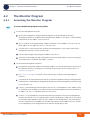
4.2.1 Accessing the Monitor Program .......................................................................... 78
4.2.2 Using the Monitor Program................................................................................. 79
4.3 IP Addresses Configuration.................................................................................81
4.3.1 IP Address Configuration Restrictions ................................................................ 81
4.3.2 IP Subnets ........................................................................................................... 81
4.4 The Main Menu...................................................................................................82
4.5 BTS Menu...........................................................................................................83
4.5.1 General ............................................................................................................... 83
4.5.2 Connectivity ........................................................................................................ 84
4.5.3 Unit Control ........................................................................................................ 90
4.5.4 Management ....................................................................................................... 95
4.6 Sector Menu ......................................................................................................98
4.6.1 Sector Definition................................................................................................. 98
4.6.2 Radio Cluster....................................................................................................... 98
4.6.3 Antenna Association........................................................................................... 99
4.7 BS Menu ..........................................................................................................100
4.7.1 Add ................................................................................................................... 100
4.7.2 Select ................................................................................................................ 102
4.8 Chassis Menu ...................................................................................................123
4.8.1 General ............................................................................................................. 123
4.8.2 Ports Control..................................................................................................... 123
4.9 GPS Menu ........................................................................................................125
4.9.1 General Configuration....................................................................................... 125
4.9.2 Inventory & Statuses ........................................................................................ 127
4.10 RH Menu.........................................................................................................129
4.10.1 General ............................................................................................................. 129
4.10.2 Ports ................................................................................................................. 129
4.11 Antenna Menu ................................................................................................131
BreezeCOMPACT System Manual
iv
Contents
4.11.1 Antenna Number............................................................................................... 131
4.11.2 Antenna Product Type ...................................................................................... 131
4.11.3 Mechanical Down Tilt ........................................................................................ 131
4.11.4 Electrical Down Tilt ........................................................................................... 131
4.11.5 Longitude.......................................................................................................... 132
4.11.6 Latitude ............................................................................................................ 132
4.11.7 Tower Height .................................................................................................... 132
4.11.8 Heading............................................................................................................. 132
4.11.9 Cable Loss ......................................................................................................... 132
BreezeCOMPACT System Manual
v
Figures
Figures
Figure 1-1: Mobile WiMAX Network Reference Model .................................................................... 3
Figure 1-2: ASN Reference Model containing Multiple ASN-GWs.................................................... 3
Figure 1-3: Centralized Network Reference Model......................................................................... 6
Figure 1-4: Distributed Network Reference Model ......................................................................... 7
Figure 1-5: One Sector, One Carrier ............................................................................................. 11
Figure 1-6: One Sector, Dual Carrier............................................................................................. 11
Figure 1-7: Two Sectors, Two Carriers (One Carrier per Sector)................................................... 12
Figure 2-1: Mounting the Sun-guard Cover................................................................................... 34
Figure 2-2: Pole Mounting without the Carriage........................................................................... 35
Figure 2-3: BTS Installed on the Pole............................................................................................ 35
Figure 2-4: Attaching the Clamps ................................................................................................. 36
Figure 2-5: BTS Installed on Poles Using Metal Bands .................................................................. 37
Figure 2-6: The Carriage, Part of the Antenna Mounting Kit ........................................................ 39
Figure 2-7: Preparing the BTS for Installation .............................................................................. 40
Figure 2-8: BTS Installed on the Carriage ..................................................................................... 41
Figure 2-9: Installing the GPS Bracket .......................................................................................... 41
Figure 2-10: Assembling the Antenna on the Carriage................................................................. 42
Figure 2-11: BTS and Attached Antenna Mounted on a 1”-4” Pole .............................................. 43
Figure 2-12: BTS and Attached Antenna Mounted Using Metal Bands ......................................... 44
Figure 2-13: Mounting the Carriage on the Wall........................................................................... 45
Figure 2-14: Pole Mounting the GPS Using Metal Bands (4” Pole)................................................ 47
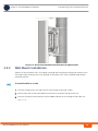
Figure 2-15: Installing the GPS Bracket ........................................................................................ 48
Figure 2-16: GPS installed on the Carriage ................................................................................... 48
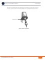
Figure 2-17: GPS Components ...................................................................................................... 49
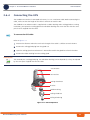
Figure 2-18: Connecting the GPS Cable ........................................................................................ 50
Figure 2-19: GPS Bottom View...................................................................................................... 50
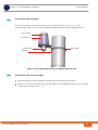
Figure 2-20: GPS Grounding.......................................................................................................... 51
BreezeCOMPACT System Manual
vi
Figures
Figure 2-21: BreezeCOMPACT with Sealing Gland Wrench............................................................ 52
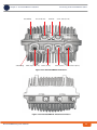
Figure 2-22: BreezeCOMPACT Connectors .................................................................................... 53
Figure 2-23: BreezeCOMPACT Antenna Connectors...................................................................... 53
Figure 2-24: Open Barrel Terminal................................................................................................ 58
Figure 2-25: Crimped Wire ............................................................................................................ 59
Figure 2-26: Inserting a Contact into the Housing ....................................................................... 59
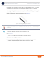
Figure 2-27: Power Cable for BreezeCOMPACT ............................................................................. 60
Figure 2-28: Sealing Gland Special Wrench................................................................................... 62
Figure 2-29: Small (7.9) Sealing Gland Components..................................................................... 63
Figure 2-30: Large (10.5) Sealing Gland Components .................................................................. 63
Figure 2-31: Antenna Connections ............................................................................................... 64
BreezeCOMPACT System Manual
vii
Tables
Tables
Table 1-1: General Modem & Radio Specifications....................................................................... 14
Table 1-2: Per Channel Sensitivity, AWGN @ PER=1%................................................................... 15
Table 1-3: Data Communication (Ethernet Interfaces) ................................................................. 15
Table 1-4: Configuration and Management .................................................................................. 16
Table 1-5: Standards Compliance, General ................................................................................... 16
Table 1-6: Environmental Specifications....................................................................................... 16
Table 1-7: Mechanical & Electrical Specifications ......................................................................... 17
Table 1-8: Attached Antenna 3.3-3.8 DDS 65º (P.N. 300726) Specifications ............................... 18
Table 1-9: ANT BS-EDT-DDP-65°-3.3-3.8GHz (P.N. 323109) Specifications.................................. 19
Table 1-10: ANT,BS,3.3-3.8GHz, DS,Sec.65°,16.5dBi min (P.N. 300644) Specifications ............... 20
Table 1-11: ANT,BS,3.3-3.8GHz, DS,Sec.90°,15.5dBi min (P.N. 300645) Specifications ............... 21
Table 1-12: ANT-DDP-65°-3.3-3.8GHz (P.N. 300720) Specifications ............................................ 22
Table 1-13: ANT-DDP-90°-3.3-3.8GHz (P.N. 300719) Specifications ............................................ 23
Table 1-14: ANT BS 3.3-3.8GHz, 90° V (P.N. 300616) Specifications............................................ 24
Table 1-15: BMAX-4M-GPS Receiver, Mechanical & Electrical Specifications................................ 25
Table 2-1: Mounting Options ........................................................................................................ 31
Table 2-2: BTS Connectors............................................................................................................ 54
Table 2-3: Wire to Pin Mapping for Data Cable for the BTS.......................................................... 56
Table 2-4: Approved Category 5E Ethernet Cables ....................................................................... 56
Table 2-5: Power Cable Pin-out .................................................................................................... 60
Table 2-6: GPS Cable Pinout.......................................................................................................... 61
Table 2-7: BreezeCOMPACT LEDs.................................................................................................. 65
Table 4-1: First Zone Minimum Size Recommended Value Range............................................... 107
Table 4-2: Calculating the Upper Limit Value (Y) for Minimum and Maximum Size ..................... 108
BreezeCOMPACT System Manual
viii
Tables
Table 4-3: DL:UL Ratios .............................................................................................................. 111
BreezeCOMPACT System Manual
ix
Chapter 1 - System Description
In This Chapter:
“About WiMAX” on page 2
“The BreezeCOMPACT Solution” on page 9
“Element Management Systems” on page 13
“Specifications” on page 14
Chapter 1 - System DescriptionAbout WiMAX
Chapter 1 - System Description
1.1
About WiMAX
1.1.1
Introduction to WiMAX
About WiMAX
Emanating from the broadband world and using all-IP architecture, mobile WiMAX is the leading
technology for implementing personal broadband services. No other technology offers a full set of
chargeable and differentiated voice, data, and premium video services in a variety of wireless fashions fixed, portable and mobile - that increase revenue and reduce subscriber churn.
WiMAX technology is the solution for many types of high-bandwidth applications at the same time
across long distances and will enable service carriers to converge the all-IP-based network for triple-play
services data, voice, and video.
WiMAX with its QoS support, longer reach, and high data capacity is positioned for fixed broadband
access applications in rural areas, particularly when distance is too large for DSL and cable, as well as in
urban/suburban areas of developing countries. Among applications for residential are high speed
Internet, Voice Over IP telephony and streaming video/online gaming with additional applications for
enterprise such as Video conferencing, Video surveillance and secured Virtual Private Network (with
need for high security). WiMAX technology allows covering applications with media content requesting
more bandwidth.
WiMAX allows portable and mobile access applications, with incorporation in notebook computers and
PDAs, allowing for urban areas and cities to become “metro zones” for portable and mobile outdoor
broadband wireless access. As such WiMAX is the natural complement to 3G networks by offering
higher bandwidth and to Wi-Fi networks by offering broadband connectivity in larger areas.
The WiMAX Forum is an organization of leading operators and communications component and
equipment companies. The WiMAX Forum’s charter is to promote and certify the compatibility and
interoperability of broadband wireless access equipment that conforms to the Institute for Electrical and
Electronics Engineers (IEEE) 802.16 and ETSI HiperMAN standards. The ultimate goal of the WiMAX
Forum is to accelerate the introduction of cost-effective broadband wireless access services into the
marketplace. Standards-based, interoperable solutions enable economies of scale that, in turn, drive
price and performance levels unachievable by proprietary approaches, making WiMAX Forum Certified
products.
1.1.2
WiMAX Network Reference Model
Figure 1-1 and Figure 1-2 show the basic mobile WiMAX network architecture, with a single ASN-GW
and with multiple ASN-GWs, as defined by the WiMAX Forum NWG
BreezeCOMPACT System Manual
2
Chapter 1 - System DescriptionAbout WiMAX
Chapter 1 - System Description
About WiMAX
.
Figure 1-1: Mobile WiMAX Network Reference Model
Figure 1-2: ASN Reference Model containing Multiple ASN-GWs
The various components and entities involved in the networking architecture are:
1.1.2.1
Access Service Network (ASN)
An ASN is defined as a complete set of network functions needed to provide radio access to a WiMAX
subscriber. The ASN provides the following mandatory functions:
BreezeCOMPACT System Manual
3
Chapter 1 - System DescriptionAbout WiMAX
Chapter 1 - System Description
About WiMAX
WiMAX Layer-2 (L2) connectivity with WiMAX mobile station (MS)
Transfer of AAA messages to the WiMAX subscriber's home network service provider (H-NSP) for
authentication, authorization and session accounting for subscriber sessions
Network discovery and selection of the WiMAX subscriber's preferred NSP
Relay functionality for establishing Layer-3 (L3) connectivity with a WiMAX MS (i.e. IP address
allocation)
Radio resource management
ASN-CSN tunneling
ASN anchored mobility
An ASN is comprised of network elements such as one or more base transceiver stations and one or
more ASN gateways. An ASN may be shared by more than one connectivity service network (CSN).
1.1.2.2
Connectivity Service Network (CSN)
A CSN is defined as a set of network functions that provide IP connectivity services to WiMAX
subscribers. A CSN may offer the following functions:
MS IP address and endpoint parameter allocation for user sessions
Internet access
AAA proxy or server
Policy and admission control based on user subscription profiles
ASN-CSN tunneling support
WiMAX subscriber billing and inter-operator settlement
WiMAX services such as location-based services, connectivity for peer-to-peer services, provisioning,
authorization and/or connectivity to IP multimedia services, and facilities to support lawful intercept
services such as those compliant with Communications Assistance Law Enforcement Act (CALEA)
procedures
A CSN is comprised of network elements such as routers, proxy/servers, user databases, and
inter-working gateway devices.
1.1.2.3
Network Access Provider (NAP)
An NAP is a business entity that provides WiMAX radio access infrastructure to one or more WiMAX
network service providers (NSPs). A NAP implements this infrastructure using one or more ASNs.
1.1.2.4
Network Service Provider (NSP)
An NSP is a business entity that provides IP connectivity and WiMAX services to WiMAX subscribers
compliant with the established service level agreement. The NSP concept is an extension of the Internet
service provider (ISP) concept, providing network services beyond Internet access. To provide these
BreezeCOMPACT System Manual
4
Chapter 1 - System DescriptionAbout WiMAX
Chapter 1 - System Description
About WiMAX
services, an NSP establishes contractual agreements with one or more NAPs. An NSP may also establish
roaming agreements with other NSPs and contractual agreements with third-party application providers
(e.g. ASP, ISP) for the delivery of WiMAX services to subscribers. From a WiMAX subscriber standpoint,
an NSP may be classified as a home or visited NSP.
1.1.2.5
Base Station (BS)
The WiMAX BS is an entity that implements the WiMAX MAC and PHY in compliance with the IEEE
802.16e standard. A BS operates on one frequency assignment, and incorporates scheduler functions
for uplink and downlink resources.
The basic functionality of the BS includes:
IEEE 802.16e OFDMA PHY/MAC entity
R6 and R8 functionality according to NWG definitions
Extensible Authentication Protocol (EAP) relay
Control message authentication
User traffic authentication and encryption
Handover management
QoS service flow management entity
1.1.2.6
ASN Gateway (ASN-GW)
The ASN-GW is a network entity that acts as a gateway between the ASN and CSN. The ASN functions
hosted in an ASN-GW may be viewed as consisting of two groups - the decision point (DP) and
enforcement point (EP). The EP includes bearer plane functions, and the DP includes non-bearer plane
functions.
The basic DP functionality of the ASN-GW includes:
Implementation of EAP Authenticator and AAA client
Termination of RADIUS protocol against the selected CSN AAA server (home or visited AAA server) for
MS authentication and per-MS policy profile retrieval
Storage of the MS policy profile
Generation of authentication key material
QoS service flow authorization entity
AAA accounting client
The basic EP functionality of the ASN-GW includes:
Classification of downlink data into generic routing encapsulation (GRE) tunnels
Packet header suppression functionality
DHCP functionality
BreezeCOMPACT System Manual
5
Chapter 1 - System DescriptionAbout WiMAX
Chapter 1 - System Description
About WiMAX
Handover functionality
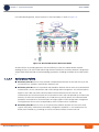
The WIMAX Forum NWG has adopted two different approaches for ASN architecture - centralized and
distributed: In the centralized approach there is at least one central ASN-GW, and the BTS operates in
transparent mode, as shown in Figure 1-3.
Figure 1-3: Centralized Network Reference Model
BreezeCOMPACT System Manual
6
Chapter 1 - System DescriptionAbout WiMAX
Chapter 1 - System Description
About WiMAX
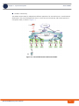
In the distributed approach, the BTS operates in ASN-GW mode, as shown in Figure 1-4.
Figure 1-4: Distributed Network Reference Model
Alvarion believes in providing operators with the flexibility to select the mobile WiMAX network
topology that best suits their needs and existing network architecture. Therefore, 4Motion is designed to
support both distributed and centralized topology approaches according to WiMAX Forum NWG profile
C.
1.1.2.7
Reference Points
Reference point R1 consists of the protocols and procedures between the MS and ASN as per the
air-interface (PHY and MAC) specifications (IEEE 802.16e).
Reference point R2 consists of protocols and procedures between the MS and CSN associated with
authentication, services authorization and IP host configuration management. This reference point is
logical in that it does not reflect a direct protocol interface between the MS and CSN. The
authentication part of reference point R2 runs between the MS and CSN operated by the home NSP,
however, the ASN and CSN operated by the visited NSP may partially process the aforementioned
procedures and mechanisms. Reference point R2 might support IP host configuration management
running between the MS and CSN (operated by either the home NSP or visited NSP).
Reference point R3 consists of the set of control plane protocols between the ASN and CSN to
support AAA, policy enforcement and mobility management capabilities. It also encompasses the
bearer plane methods (e.g. tunneling) to transfer user data between the ASN and CSN.
BreezeCOMPACT System Manual
7
Chapter 1 - System DescriptionAbout WiMAX
Chapter 1 - System Description
About WiMAX
Reference point R4 consists of the set of control and bearer plane protocols originating/terminating
in various functional entities of an ASN that coordinate MS mobility between ASNs and ASN-GWs. R4
is the only interoperable reference point between similar or heterogeneous ASNs.
Reference point R5 consists of the set of control plane and bearer plane protocols for
internetworking between the CSN operated by the home NSP and that operated by a visited NSP.
Reference point R6 consists of the set of control and bearer plane protocols for communication
between the BS and ASN-GW. The bearer plane consists of an intra-ASN data path between the BS
and ASN gateway. The control plane includes protocols for data path establishment, modification and
release control in accordance with the MS mobility events.
Reference point R8 consists of the set of control plane message flows and optional bearer plane
data flows between the base stations to ensure a fast and seamless handover. The bearer plane
consists of protocols that allow data transfer between base stations involved in the handover of a
certain MS.
It is important to note that all reference points are logical and do not necessarily imply a physical or even
direct connection. For instance, the R4 reference point between ASN-GWs might be implemented across
the NAP internal transport IP network, in which case R4 traffic might traverse several routers from the
source to the destination ASN-GW.
BreezeCOMPACT System Manual
8
Chapter 1 - System DescriptionThe BreezeCOMPACT Solution
Chapter 1 - System Description
1.2
The BreezeCOMPACT Solution
1.2.1
BreezeCOMPACT Highlights
The BreezeCOMPACT Solution
BreezeCOMPACT is a small, lightweight, all-outdoor single box base transceiver station enabling easy
installation and maintenance and reduced Total Cost of Ownership (TCO).
BreezeCOMPACT enhances Alvarion's 4Motion product portfolio of BreezeMAX Macro and Micro BTS
systems with a compact all-outdoor 4x4 platform enabling extended and flexible installation capabilities
while sustaining 4Motion leading technological advantages and ecosystem.
BreezeCOMPACT is a weatherized carrier-class WiMAX 802.16e platform, based on Software Defined
Radio (SDR) that is SW upgradable for new technologies such as Time-Division Long-Term Evolution
(TD-LTE) and IEEE. It is an integral part of 4Motion end-to-end solution. BreezeCOMPACT BTS
complements Alvarion's Macro BTS products for coverage and capacity extension as well as rural
deployment scenarios.
BreezeCOMPACT is a reliable platform utilizing the mature field-proven 4Motion modules and
ecosystem elements (e.g. ASN-GW, AAA, and WiMAX™ devices), hence delivering high product
availability.
Portable and mobile subscribers can connect to BreezeCOMPACT base station through various end-user
terminals such as USB dongles, Self Installed (SI) Residential Gateways (RGW), and Outdoor CPEs.
Alvarion's Compact, Micro and Macro solutions share similar functionality with same ecosystem,
allowing flexible mix & match approach to address various operator deployment needs.
Alvarion believes that compliance with standard-driven open architecture protects the infrastructure
investment, and opens the system to a variety of fully interoperable end-user devices. As such, 4Motion
is designed with open architecture and interfaces according to the WiMAX Forum networking working
group (NWG) profile C, which supports openness and enables flat as well as hierarchical topologies. In
addition, by keeping the radio resource management functionality in the Base Transceiver Station only,
Profile C delivers a faster, optimized handover mechanism.
1.2.2
Network Architectures
BreezeCOMPACT supports different network architectures:
External ASN-GW
Embedded ASN-GW Local Authentication
Embedded ASN-GW Centralized Authentication
INFORMATION
In the current release only External ASN-GW network architecture is supported.
BreezeCOMPACT System Manual
9
Chapter 1 - System DescriptionThe BreezeCOMPACT Solution
Chapter 1 - System Description
The BreezeCOMPACT Solution
Following is a description of each of these working modes:
1.2.2.1
External ASN-GW
The ASN-GW is a separate entity (centralized architecture) that communicates with the BTS over R6
interface. Service components (Service Profiles and Service Flows) are configured in the external
ASN-GW. MS authentication and services provisioning are managed by a centralized AAA server, based
on user credentials (user name and password).
1.2.2.2
Embedded ASN-GW Local Authentication
The ASN-GW functionality resides in the BTS (distributed architecture). Service components (Service
Profiles and Service Flows) are configured in the internal ASN-GW of each BTS. MSs list and services
provisioning including authentication are managed locally by the internal ASN-GW (AAA server not
needed), based on the SU MAC address.
1.2.2.3
Embedded ASN-GW Centralized Authentication
The ASN-GW functionality resides in the BTS (distributed architecture). Service components (Service
Profiles and Service Flows) are configured locally in the BTS. MS authentication and service provisioning
are managed centrally by an external AAA server, based on user credentials (user name and password).
1.2.3
System Topologies
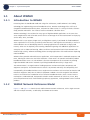
BreezeCOMPACT supports different system topologies:
One Sector, One Carrier
One Sector, Dual Carrier
Two Sector, Two Carriers (One Carrier per Sector)
INFORMATION
In the current release only One Sector, One Carrier topology with a 10 MHz bandwidth is supported.
In the current release only 4Rx by 2Tx (4x2) and 2Rx by 2Tx (2x2) configurations are supported.
Following is a description of each of these topologies:
1.2.3.1
One Sector, One Carrier
This is the basic configuration based on a single BS, supporting a single 4x4 sector with a bandwidth of
5, 7, or 10 MHz.
BreezeCOMPACT System Manual
10
Chapter 1 - System DescriptionThe BreezeCOMPACT Solution
Chapter 1 - System Description
The BreezeCOMPACT Solution
Figure 1-5: One Sector, One Carrier
1.2.3.2
One Sector, Dual Carrier
Two BSs support a single 4x4 sector with a total bandwidth of 20 (10+10) or 14 (7+7) MHz.
Figure 1-6: One Sector, Dual Carrier
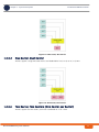
1.2.3.3
Two Sector, Two Carriers (One Carrier per Sector)
Two BSs support two 2x2 sectors, each with a bandwidth of 10 or 7 MHz.
BreezeCOMPACT System Manual
11
Chapter 1 - System DescriptionThe BreezeCOMPACT Solution
Chapter 1 - System Description
The BreezeCOMPACT Solution
Figure 1-7: Two Sectors, Two Carriers (One Carrier per Sector)
1.2.4
Antennas
In the 4Motion architecture, the antenna is approached as an independent element. This provides the
operator with the flexibility to select the antennas source according to its supplier policy. To ensure the
availability of antennas that complement the 4Motion solution, Alvarion works closely with several
antenna suppliers to ensure availability of antennas that comply with its requirements.
In cases where the operator prefers other antenna vendors, Alvarion can provide a recommended
antenna specification based on the required antennas types.
Antennas may support mechanical down-tilt (MDT) using a suitable mounting kit, or electrical down-tilt
(EDT) that may be either fixed or adjustable using a special adjustment screw.
In addition to a range of standard commercial antennas, Alvarion offers also a special attached antenna
design for convenient installation on top of the BreezeCOMPACT unit.
For details on antennas offered by Alvarion refer to “Antennas” on page 18.
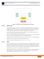
1.2.5
GPS
GPS is used to synchronize the air link frames of Intra-site and Inter-site located Base Transceiver Stations
to ensure that in all Base Stations the air frame will start at the same time, and that all Base Stations will
switch from transmit (downlink) to receive (uplink) at the same time. This synchronization is necessary to
prevent Intra-site and Inter-site interference and Base Stations saturation (assuming that all Base Stations
are operating with the same frame size and with the same DL/UL ratio).
The all-outdoor GPS Receiver is a pole mountable GPS receiver and antenna in a single environmentally
protected enclosure that is powered from the unit. GPS signals chaining (not supported in current
release) enables using a single GPS receiver for several collocated units.
BreezeCOMPACT System Manual
12
Chapter 1 - System DescriptionElement Management Systems
Chapter 1 - System Description
1.3
Element Management Systems
Element Management Systems
The end-to-end IP-based architecture of the system enables full management of all components, using
standard management tools. An SNMP agent in the NPU implements proprietary MIBs for remote setting
of operational modes and parameters of the Base Transceiver Station equipment. Security features
incorporated in the equipment restrict the access for management purposes.
Alvarion offers the following management tool:
1.3.1
AlvariSTAR
AlvariSTAR is a comprehensive carrier-class Element Management System (EMS) for Alvarion’s Broadband
Wireless Access systems. AlvariSTAR is designed for today's most advanced Network Operation Centers
(NOCs), providing the network Operation, Administration and Maintenance (OA&M) staff and managers
with all the network surveillance, monitoring and configuration and service provisioning capabilities
required to effectively manage the network while keeping the resources and expenses at a minimum.
AlvariSTAR offers the network's OA&M staff with a unified, scalable and distributable management
system. Utilizing distributed client-server architecture, the user is provided with a robust, scalable and
fully redundant management system in which all single points of failure can be avoided.
AlvariSTAR provides the following management functionality:
Device Discovery
Device Inventory
Topology
Fault Management
Configuration Management
Service Management
Data Collection
Performance Monitoring
Device embedded software upgrade
Template-based configuration modification of multiple BTS simultaneously.
Preparation of offline configuration files for a single BTS or for mass configuration of new BTSs.
Dynamic Web Portal including a live map, graphs, quick search and more
Predefined Reports
Security Management
Event Forwarding to other Network Management Systems.
BreezeCOMPACT System Manual
13
Chapter 1 - System DescriptionSpecifications
Chapter 1 - System Description
1.4
Specifications
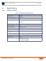
1.4.1
Modem & Radio
Specifications
Table 1-1: General Modem & Radio Specifications
Item
Description
Frequency Band
3400-3675
Central Frequency Resolution
0.125 MHz
Operation Mode
TDD
Channel Bandwidth
5 MHz
7 MHz
10 MHz
Bandwidth Support
Up to 20 MHz
Ports Configuration
4x4
Maximum Tx Power
27 dBm per channel
Tx Power Control Range
10 dB, in 1 dB steps
Tx Power Accuracy
+/- 1 dB
Maximum Input Power @
antenna port
-45 dBm before saturation, -35 dBm before damage
Noise Figure
5 dB
Modulation
OFDM modulation, 1024/512 FFT points; QPSK, QAM16, QAM64
Access Method
OFDMA
FEC
Convolutional Turbo Coding:
1/2, 3/4 for QPSK and QAM16.
1/2, 2/3, 3/4, 5/6 for QAM64
BreezeCOMPACT System Manual
14
Chapter 1 - System DescriptionSpecifications
Chapter 1 - System Description
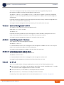
1.4.2
Specifications
Sensitivity (per channel)*
Table 1-2: Per Channel Sensitivity, AWGN @ PER=1%
Modulation & Coding
Sensitivity (dBm),
5 MHz Bandwidth
Sensitivity (dBm),
7 MHz Bandwidth
Sensitivity (dBm),
10 MHz Bandwidth
QPSK 1/2 Repetition 6
-102
-100
-99
QPSK 1/2 Repetition 4
-101
-99
-98
QPSK 1/2 Repetition 2
-99
-97
-96
QPSK 1/2
-96
-94
-93
QPSK 3/4
-93
-91
-90
16QAM 1/2
-90
-88
-87
16QAM 3/4
-85
-83
-82
64QAM1/2
-84
-82
-81
64QAM2/3
-82
-79
-78
64QAM3/4
-80
-78
-77
64QAM5/6
-78
-76
-75
* For second order receive diversity configurations sensitivity is improved by 3 dB. For fourth order
receive diversity configurations sensitivity is improved by 6 dB.
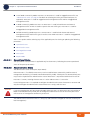
1.4.3
Data Communication (Ethernet Interfaces)
Table 1-3: Data Communication (Ethernet Interfaces)
Item
Description
Standard Compliance
IEEE 802.3 CSMA/CD
DAT 1 (optional, if an SFP is installed)
1000 Mbps Base-X optical fiber interface, Half/Full Duplex
with Auto Negotiation.
DAT 2
100/1000 Mbps Base-T twisted-pair electrical interface,
Half/Full Duplex with Auto Negotiation.
DAT 3
10/100 Mbps Base-T twisted-pair electrical interface, Half/Full
Duplex with Auto Negotiation. When using PoE, connect
only equipment approved by Alvarion.
BreezeCOMPACT System Manual
15
Chapter 1 - System DescriptionSpecifications
Chapter 1 - System Description
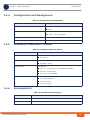
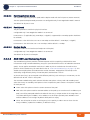
1.4.4
Specifications
Configuration and Management
Table 1-4: Configuration and Management
Item
Description
Management (Out Of Band, In Band)
SNMP
Telnet
SNMP Agents
SNMP Ver. 2 client
MIB II (RFC 1213), Private MIBs
1.4.5
Software Upgrade
Using TFTP
Configuration Upload/Download
Using TFTP
Standards Compliance, General
Table 1-5: Standards Compliance, General
Type
Standard
EMC
ETSI EN 301 489-1/4
FCC Part 15
EN60950-1 (CE)
Safety
UL 60950-1 (US/C)
Environmental
ETS 300 019:
Part 2-1 T 1.2 & part 2-2 T 2.3 for indoor & outdoor
Part 2-3 T 3.2 for indoor
Part 2-4 T 4.1E for outdoor
ETSI EN 302 326
Radio
FCC Part 90 Subpart Z
IC RSS-192 issue1
IC RSS-197 issue 3
1.4.6
Environmental
Table 1-6: Environmental Specifications
Type
Details
Operating Temperature
-40°C to 55°C
Operating Humidity
5%-95%, weather protected
BreezeCOMPACT System Manual
16
Chapter 1 - System DescriptionSpecifications
Chapter 1 - System Description
1.4.7
Specifications
Mechanical and Electrical
Table 1-7: Mechanical & Electrical Specifications
Item
Description
Dimensions
242.7 x 343 x 166.9 mm
Weight
8.2 Kg
Power Source
-40 to -60 VDC
Power Consumption
125 W peak
BreezeCOMPACT System Manual
17
Chapter 1 - System DescriptionSpecifications
Chapter 1 - System Description
Specifications
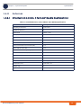
1.4.8
Antennas
1.4.8.1
Attached, 3.3-3.8 GHz, 4 Ports 65º Double Dual Slant (xx)
Table 1-8: Attached Antenna 3.3-3.8 DDS 65º (P.N. 300726) Specifications
Item
Description
Frequency Band (MHz)
3300-3800
Number of Elements
4
Polarization
Linear, +/-45°
Gain (dB)
18
Azimuth Beamwidth (degrees)
65
Elevation Beamwidth (degrees)
6.5
Maximum Power (W)
150
Cross-polarization Discrimination (dB)
>15
Front-to-Back Ratio (dB)
>30
Electrical Downtilt Range (degrees)
0
Isolation Between Ports (dB)
>30
Return Loss (dB)
>15
RF Interface Impedance (Ohm)
50
RF Connectors
4 x N-Type jacks with RF cable tails
Dimensions (mm)
720x 266 x 52
Weight (Kg)
4
Regulatory Compliance
RoHS Compliance
BreezeCOMPACT System Manual
18
Chapter 1 - System DescriptionSpecifications
Chapter 1 - System Description
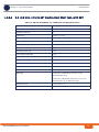
1.4.8.2
Specifications
3.3 -3.8 GHz, 4 Ports 65º Double Dual Slant (xx), with EDT
Table 1-9: ANT BS-EDT-DDP-65°-3.3-3.8GHz (P.N. 323109) Specifications
Item
Description
Frequency Band (MHz)
3300-3800
Number of Elements
4
Polarization
Linear, 2 x +/-45°
Gain (dB)
18
Azimuth Beamwidth (degrees)
65
Elevation Beamwidth (degrees)
6.5° with nullfill
Elevation Side Lobe Level (dB)
<-18
Maximum Power (W)
150
Front-to-Back Ratio (dB)
>30
Electrical Downtilt Range
0° - 10° independently continuously adjustable
Isolation Between Ports (dB)
>30
Return Loss (dB)
>15
RF Interface Impedance (Ohm)
50
RF Connectors
4 x N-Type jack
Mounting
F-042-GL-E: Fixed clamps for 50-115 mm
diameter pipe, 5Kg
T-045-GL-E: Adjustable clamps for 50-115 mm
diameter pipe, 0-10° down tilt, 6Kg
Dimensions (mm)
750 x 300 x 115
Weight (Kg)
10
BreezeCOMPACT System Manual
19
Chapter 1 - System DescriptionSpecifications
Chapter 1 - System Description
1.4.8.3
Specifications
3.3 -3.8 GHz, 2 Ports 65º Dual Slant (x)
Table 1-10: ANT,BS,3.3-3.8GHz, DS,Sec.65°,16.5dBi min (P.N. 300644) Specifications
Item
Description
Frequency Band (MHz)
3300-3800
Number of Elements
2
Polarization
Linear, +/-45°
Gain
16.5dBi +/- 0.5dB
VSWR
1.5:1 (max)
Azimuth Beamwidth (degrees)
65 +/-5
Elevation Beamwidth (degrees)
6 +/-1
Maximum Power (W)
50
Cross-polarization Discrimination (dB)
-15
Front-to-Back Ratio (dB)
>25
Isolation Between Ports (dB)
>25
RF Interface Impedance (Ohm)
50
Lightning Protection
DC grounded
RF Connectors
2 x N-Type jacks
Mounting
Fully adjustable pipe mount (1.63” to 4.5” pipe)
with 0-15° down tilt
Dimensions (mm)
711 x 171 x 90
Weight (Kg)
2.6 (excluding mounting kit)
Regulatory Compliance
RoHS Compliance
BreezeCOMPACT System Manual
20
Chapter 1 - System DescriptionSpecifications
Chapter 1 - System Description
1.4.8.4
Specifications
3.3 -3.8 GHz, 2 Ports 90º Dual Slant (x)
Table 1-11: ANT,BS,3.3-3.8GHz, DS,Sec.90°,15.5dBi min (P.N. 300645) Specifications
Item
Description
Frequency Band (MHz)
3300-3800
Number of Elements
2
Polarization
Linear, +/-45°
Gain
15.5dBi +/- 0.5dB
VSWR
1.5:1 (max)
Azimuth Beamwidth (degrees)
85 +/-5
Elevation Beamwidth (degrees)
6 +/-1
Maximum Power (W)
50
Cross-polarization Discrimination (dB)
-17
Front-to-Back Ratio (dB)
>25
Isolation Between Ports (dB)
>25
RF Interface Impedance (Ohm)
50
Lightning Protection
DC grounded
RF Connectors
2 x N-Type jacks
Mounting
Fully adjustable pipe mount (1.63” to 4.5” pipe)
with 0-15° down tilt
Dimensions (mm)
711 x 171 x 90
Weight (Kg)
2.6 (excluding mounting kit)
Regulatory Compliance
RoHS Compliance
BreezeCOMPACT System Manual
21
Chapter 1 - System DescriptionSpecifications
Chapter 1 - System Description
1.4.8.5
Specifications
3.3 -3.8 GHz, 4 Ports 65º Double Dual Slant (xx)
Table 1-12: ANT-DDP-65°-3.3-3.8GHz (P.N. 300720) Specifications
Item
Description
Frequency Band (MHz)
3300-3800
Number of Elements
4
Polarization
Linear, 2 x +/-45°
Gain
18dBi
Azimuth Beamwidth (degrees)
65
Elevation Beamwidth (degrees)
7
Maximum Power (W)
150
Cross-polarization Discrimination (dB)
>15
Front-to-Back Ratio (dB)
>30
Isolation Between Ports (dB)
>30
Return Loss (dB)
>15
Upper Sidelobe Suppression (dB)
>18
RF Interface Impedance (Ohm)
50
Lightning Protection
DC grounded
RF Connectors
4 x N-Type jack
Electrical Downtilt
4° (fixed)
Mounting
Adjustable mounting kit (optional) for 50-115mm
pole, with +2° to -10° tilt range
Dimensions (mm)
720 x 260 x 55
Weight (Kg)
7 (excluding mounting kit)
BreezeCOMPACT System Manual
22
Chapter 1 - System DescriptionSpecifications
Chapter 1 - System Description
1.4.8.6
Specifications
3.3 -3.8 GHz, 4 Ports 90º Double Dual Slant (xx)
Table 1-13: ANT-DDP-90°-3.3-3.8GHz (P.N. 300719) Specifications
Item
Description
Frequency Band (MHz)
3300-3800
Number of Elements
4
Polarization
Linear, 2 x +/-45°
Gain
17dBi
Azimuth Beamwidth (degrees)
90
Elevation Beamwidth (degrees)
7
Maximum Power (W)
150
Cross-polarization Discrimination (dB)
>15
Front-to-Back Ratio (dB)
>30
Isolation Between Ports (dB)
>30
Return Loss (dB)
>15
Upper Sidelobe Suppression (dB)
>18
RF Interface Impedance (Ohm)
50
Lightning Protection
DC grounded
RF Connectors
4 x N-Type jack
Electrical Downtilt
4° (fixed)
Mounting
Adjustable mounting kit (optional) for 50-115mm
pole, with +2° to -10° tilt range
Dimensions (mm)
720 x 260 x 55
Weight (Kg)
7 (excluding mounting kit)
BreezeCOMPACT System Manual
23
Chapter 1 - System DescriptionSpecifications
Chapter 1 - System Description
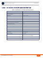
1.4.8.7
Specifications
3.3 -3.8 GHz, 90º Vertical
Table 1-14: ANT BS 3.3-3.8GHz, 90° V (P.N. 300616) Specifications
Item
Description
Frequency Band (MHz)
3300-3800
Number of Elements
1
Polarization
Vertical
Gain
14.5dBi (min)
VSWR
1.8:1 (max)
Azimuth Beamwidth (degrees)
90
Elevation Beamwidth (degrees)
7
Maximum Power (W)
10
RF Interface Impedance (Ohm)
50
Lightning Protection
DC grounded
RF Connectors
2 x N-Type jacks
Mounting
Tilt Mounting Kit for 2” to 4.5” Dia. pole
Dimensions (mm)
766 x 150 x 86
Weight (Kg)
2.2 (excluding mounting kit)
Regulatory Compliance
ESTI EN 302 085 V.1.1.2 (2001-02) CS3
RoHS Compliance
BreezeCOMPACT System Manual
24
Chapter 1 - System DescriptionSpecifications
Chapter 1 - System Description
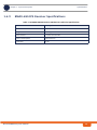
1.4.9
Specifications
BMAX-4M-GPS Receiver Specifications
Table 1-15: BMAX-4M-GPS Receiver, Mechanical & Electrical Specifications
Item
Description
Dimensions
8.8 x 10.4 x 16 cm
Weight
0.38 Kg
Power Source
12 VDC from the BTS
Power Consumption
2W maximum
Connector
RJ-45
BreezeCOMPACT System Manual
25
Chapter 2 - BreezeCOMPACT
Installation
In this Chapter:
“Introduction” on page 27
“Unpacking and Inspecting” on page 28
“BreezeCOMPACT Installation” on page 33
“Connecting the BreezeCOMPACT Cables” on page 52
“System Initial Verification” on page 65
“GPS Installation” on page 46
Chapter 2 - BreezeCOMPACT InstallationIntroduction
Chapter 2 - BreezeCOMPACT Installation
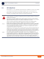
2.1
Introduction
Introduction
BreezeCOMPACT is a small, lightweight, optimized single box, all-outdoor base station system enabling
easy installation and maintenance, thus reducing the operator's Total Cost of Ownership (TCO).
BreezeCOMPACT allows flexible mounting options including rooftops, walls, poles and top towers
installation, thus providing an effective solution for installation-constrained areas.
CAUTION
ONLY experienced installation professionals who are familiar with local building and safety codes and,
wherever applicable, are licensed by the appropriate government regulatory authorities should install
outdoor units and antennas.
Failure to do so may void the product warranty and may expose the end user or Service Provider to
legal and financial liabilities. Alvarion and its resellers or distributors are not liable for injury, damage or
regulation violations associated with the installation of Outdoor Units or antennas.
Français
SEULS les installateurs professionnels expérimentés qui sont familiers avec les codes locaux des
bâtiments et de la sécurité et, lorsque cela s'applique, qui sont autorisés par les autorités
gouvernementales de régulation, doivent installer les unités extérieures et les antennes. Le non-respect
de cette clause peut invalider la garantie du produit et exposer l'utilisateur final ou le prestataire de
services à des responsabilités légales et financières. Le fabricant et ses revendeurs ou distributeurs ne
sont pas responsables pour toute blessure, dommage ou violation de la réglementation associée à
l'installation d'unités extérieures ou d'antennes.
Italiano
ATTENZIONE: SOLO professionisti esperti che hanno familiarità con le norme di costruzione locali e coi
codici di sicurezza e, ove applicabile, sono autorizzati dalle autorità governative competenti possono
installare unità esterne ed antenne. Assicurarsi che le unità esterne, antenne e strutture di supporto
siano installate correttamente per eliminare ogni pericolo fisico a persone o cose. In caso contrario, ciò
può invalidare la garanzia del prodotto e può esporre l'utente finale o il fornitore di servizi a
responsabilità legali ed economiche. Anche quando la messa a terra non è obbligatoria in base alla
normativa regolatoria applicabile e ai codici nazionali, è obbligatorio garantire che l'unità esterna e il
palo dell'antenna siano messi a terra e idonei dispositivi di protezione contro i fulmini siano utilizzati in
modo da fornire protezione contro le sovratensioni e le scariche statiche. In ogni caso, il Fornitore e i
suoi rivenditori non sono responsabili per eventuali danni fisici, danni ad oggetti o violazioni del
regolamento associati con o causati dall' installazione, la messa a terra o di protezione contro i fulmini.
BreezeCOMPACT System Manual
27
Chapter 2 - BreezeCOMPACT InstallationUnpacking and Inspecting
Chapter 2 - BreezeCOMPACT Installation
2.2
Unpacking and Inspecting
Unpacking and Inspecting
1 Examine the shipping container for damage. If you notice any damage, notify the carrier that
delivered the unit immediately and enter a service call in Alvarion's SSM (www.alvarion.com >
Customer Service area).
2 Check the items against this manual. If any items are missing, notify your agent immediately.
3 Remove the packing material without damaging it.
4 Components susceptible to damage from static electricity are packed in static resistant bags. Unpack
these items in a static-free environment to avoid damage.
BreezeCOMPACT System Manual
28
Chapter 2 - BreezeCOMPACT InstallationUnpacking and Inspecting
Chapter 2 - BreezeCOMPACT Installation
2.2.1
Unpacking and Inspecting
Package Content
BTS (weight: 9 kg)
Mounting kit (for 1''-4'' poles) including:
»
4 x heavy duty metal clamps
»
4 x M8 threaded rods
»
4 x M8x22 Hex screws
»
8 x M8 nuts
»
8 x M8 flat washers
»
8 x M8 spring washers
Hook for carrying the assembly up the pole
Sealing gland wrench
For poles up to 6'' - an additional kit containing 4 metal bands (ordered separately)
For poles larger than 6” and for wall mount - two large heavy duty metal clamps (ordered separately)
2.2.2
Additional Installation Requirements
The following items are also required to install the BTS:
INFORMATION
Items marked with an asterisk (*) are available from Alvarion.
Power Supply: High power AC/DC Power Supply unit
Power cable*: a 50m cable with connectors, or a 250m power cable drum.
Ethernet cable*: a 250m CAT5e cable drum (connectors not included)
Optional items for optical solution connection*:
»
SFP (small form-factor pluggable - optical transceiver) with each cable
»
Optical Fiber cable with LC connectors (50m or 100m)
Antenna(s)* and RF cable(s)* for connecting the antenna(s) to the BTS (applicable for units without
integral antennas). External antennas are connected via LMR-400 1m / 0.5m cables.
Antenna mounting kit*
For installation without an attached antenna - sun-guard cover*
BreezeCOMPACT System Manual
29
Chapter 2 - BreezeCOMPACT InstallationUnpacking and Inspecting
Chapter 2 - BreezeCOMPACT Installation
Unpacking and Inspecting
GPS mounting kit*
GPS bracket* for mounting on an attached antenna carriage
Mounting bands* (for 4" to 6" poles)
Grounding 10 AWG cable with an appropriate termination
Installation tools and materials
Wall mounting bracket*
For wall mount installation - four suitable dowels and screws
Complementary products:
»
Maintenance Cabinet - required for backup batteries, power system, AC/DC power adaptors and
local transport/backhauling equipment
»
Auxiliary Box - required for Dry Contact alarms, connectivity controllers, and easy access to
technical support
2.2.3
Mounting Options
Use the following table as a reference for installation, depending on your system configuration.
BreezeCOMPACT System Manual
30
Chapter 2 - BreezeCOMPACT Installation
Unpacking and Inspecting
Table 2-1: Mounting Options
Configuration
Option
Use these items/kits
Refer to
Standalone (without an
attached antenna)
Pole mount - poles
between 1” - 4”
Pole mount kit (four clamps),
supplied with the unit.
“To mount the BTS on a pole of up to 4”
(using clamps):” on page 34
Example
Sun-guard cover
Pole mount - poles up
to 6”
Metal bands
Pole mount kit (two clamps only)
“To mount the BTS on a pole of up to
6”(using metal bands):” on page 36
Sun-guard cover
With an attached
antenna
Pole mount - poles
between 1” - 4”
Antenna
Pole mount kit
Antenna mounting kit (includes
carriage and parts to attach the
antenna)
BreezeCOMPACT System Manual
“Pole Mounting with an Attached
Antenna” on page 38
“To prepare for mounting on a 1”-4”
pole:” on page 39
“To mount the antenna:” on page 42
31
Chapter 2 - BreezeCOMPACT Installation
Unpacking and Inspecting
Table 2-1: Mounting Options
Configuration
Option
Use these items/kits
Refer to
With an attached
antenna
Pole mount - poles up
to 6”
Pole mount kit (supplied with the
unit)
1 “To prepare for mounting on a pole up
to 6'' (using metal bands):” on page 42
Metal bands
2 “To mount the antenna:” on page 42
Example
Antenna
Antenna mounting kit (includes
carriage and parts to attach the
antenna)
Standalone
Wall mount
Wall mount kit
“Wall Mount Installation” on page 44
Sun-guard cover
With an attached
antenna
Wall mount
Antenna
1 “To mount the antenna:” on page 42
Antenna mounting kit (includes
carriage and parts to attach the
antenna)
2 “Wall Mount Installation” on page 44
Wall mount kit
BreezeCOMPACT System Manual
32
Chapter 2 - BreezeCOMPACT InstallationBreezeCOMPACT Installation
Chapter 2 - BreezeCOMPACT Installation
2.3
BreezeCOMPACT Installation
BreezeCOMPACT Installation
INFORMATION
Install the unit with the bottom panel, including the LEDs, facing downward. Note the direction arrows
(UP) on the sides of the BTS.
CAUTION
The weight of the BTS is 9 kg and the weight of the Pole Mounting Kit is approximately 5 kg. Make sure
to plan the installation accordingly. It is recommended to use a harness and carrying hook to lift the
units.
Install the unit using the supplied kit only.
2.3.1
Installing the BTS on a Pole
The BTS can be installed on poles of various sizes using the supplied mounting kits.
For poles of 1''-4'' in diameter, use the supplied metal clamps.
For larger poles (up to 6”) use the metal bands and two clamps out of the four included in the pole
mount kit.
When an attached antenna is to be installed together with the BTS, use the carriage mounting kit, which
includes a carriage and parts to attach the antenna. Install the BTS and the antenna on the ground and
then lift the assembly up the pole using the carrying hook.
CAUTION
Do not use the hook for lifting the assembly when the GPS is installed on the carriage. This may damage
the GPS. Tie the carriage on both sides and carefully lift it up the pole.
BreezeCOMPACT System Manual
33
Chapter 2 - BreezeCOMPACT InstallationPole Mounting without an Attached Antenna (Standalone)
Chapter 2 - BreezeCOMPACT Installation
Pole Mounting without an Attached Antenna (Standalone)
2.4
Pole Mounting without an Attached Antenna
(Standalone)
When not using the attached antenna, mount the BTS on the pole using the pole mount kit supplied
with the BTS. Attach the sun-guard cover to protect from extreme heat.
To mount the sun-guard cover:
Thread the screws through the designated holes in the cover and attach to the BTS. Fasten firmly.
Sun-guard
Screws
Holes
Figure 2-1: Mounting the Sun-guard Cover
To mount the BTS on a pole of up to 4” (using clamps):
Refer to Figure 2-2 and Figure 2-3.
1 Thread the four rods through the nuts, washers, spring washers, and two clamps, and fasten the
clamps to the BTS mounting holes.
2 Attach the BTS with the mounted clamps to the pole.
BreezeCOMPACT System Manual
34
Chapter 2 - BreezeCOMPACT InstallationPole Mounting without an Attached Antenna (Standalone)
Chapter 2 - BreezeCOMPACT Installation
Pole Mounting without an Attached Antenna (Standalone)
3 Thread the other two clamps to the rods and use the nuts washers and spring washers to fasten and
fix the BTS to the pole.
Figure 2-2: Pole Mounting without the Carriage
Figure 2-3: BTS Installed on the Pole
BreezeCOMPACT System Manual
35
Chapter 2 - BreezeCOMPACT InstallationPole Mounting without an Attached Antenna (Standalone)
Chapter 2 - BreezeCOMPACT Installation
Pole Mounting without an Attached Antenna (Standalone)
To mount the BTS on a pole of up to 6”(using metal bands):
Refer to Figure 2-4 and Figure 2-5.
1 Thread two metal bands through the designated grooves in two clamps.
2 Attach the clamps to the BTS and use the screws, washers and spring washers to fasten the clamps to
the BTS (Figure 2-4)
3 Close and fasten the bands.
Grooves for Metal Bands
Clamps
Screws, Washers
and Spring Washers
Metal Bands on
Clamps
Figure 2-4: Attaching the Clamps
BreezeCOMPACT System Manual
36
Chapter 2 - BreezeCOMPACT InstallationPole Mounting without an Attached Antenna (Standalone)
Chapter 2 - BreezeCOMPACT Installation
Pole Mounting without an Attached Antenna (Standalone)
Figure 2-5: BTS Installed on Poles Using Metal Bands
BreezeCOMPACT System Manual
37
Chapter 2 - BreezeCOMPACT InstallationPole Mounting with an Attached Antenna
Chapter 2 - BreezeCOMPACT Installation
Pole Mounting with an Attached Antenna
2.5
Pole Mounting with an Attached Antenna
When using the attached antenna, you first mount the BTS on the carriage, then also the antenna (and
optionally GPS), and finally lift the assembly up the pole, attach the clamps/metal bands and fasten the
screws.
2.5.1
Package Content
Antenna
Antenna mounting kit, including:
»
One carriage
»
2 x Antenna tilting arms
»
6 x M8 Hex nuts
»
6 x M8x22 screws
»
6 x M8 flat washers
»
6 x M8 spring washers
Pole mount kit - use the following parts:
»
Clamps/metal bands depending on pole diameter
»
4 rods
»
8 x nuts, washers, and spring washers
BreezeCOMPACT System Manual
38
Chapter 2 - BreezeCOMPACT InstallationPole Mounting with an Attached Antenna
Chapter 2 - BreezeCOMPACT Installation
Pole Mounting with an Attached Antenna
Holes for external
antenna kit
screws (x4)
Grooves for
metal bands
Holes for fastening
screws (x6)
Holes for pole
mounting rods (x4)
Holes for external
antenna kit screws (x2)
Figure 2-6: The Carriage, Part of the Antenna Mounting Kit
2.5.2
CAUTION
Mounting the BTS and Antenna on the Carriage
The weight of BTS is 9 Kg and the weight of the Pole Mounting Kit is approximately 5 kg. Plan the
installation accordingly. It is recommended to use a harness to lift the units.
Install the unit using the supplied kit only.
To prepare for mounting on a 1”-4” pole:
1 Attach the M8x20 nuts, washers and spring washers to the BTS and slightly fasten.
BreezeCOMPACT System Manual
39
Chapter 2 - BreezeCOMPACT InstallationPole Mounting with an Attached Antenna
Chapter 2 - BreezeCOMPACT Installation
Pole Mounting with an Attached Antenna
Carrying hook
M8x20 nuts, washers
and spring washers
Figure 2-7: Preparing the BTS for Installation
2 Hang the BTS screws on the BTS carriage hanging hooks. Locate the carriage hooks between the
washers and the BTS.
3 Insert the four threaded rods through the holes in the carriage. If you intend to mount the GPS on the
carriage, thread the rods through the GPS bracket as well (Refer to “To install the GPS on the
carriage:” on page 47’ and Figure 2-9).
4 Attach nuts, washers and spring washers to both sides of the threaded rods and fasten to fix the rods
in place on the carriage (Figure 2-8).
BreezeCOMPACT System Manual
40
Chapter 2 - BreezeCOMPACT InstallationPole Mounting with an Attached Antenna
Chapter 2 - BreezeCOMPACT Installation
Pole Mounting with an Attached Antenna
M8x20 nuts, washers and
spring washers on both
sides of the carriage
Hanging hooks
Figure 2-8: BTS Installed on the Carriage
M8x20 nuts, washers and
spring washers on both
sides of the carriage
GPS Bracket (optional)
Figure 2-9: Installing the GPS Bracket
BreezeCOMPACT System Manual
41
Chapter 2 - BreezeCOMPACT InstallationPole Mounting with an Attached Antenna
Chapter 2 - BreezeCOMPACT Installation
Pole Mounting with an Attached Antenna
To prepare for mounting on a pole up to 6'' (using metal bands):
1 Mount the BTS on the carriage as described in step 1-2 above.
2 Thread two metal bands through the grooves on the carriage.
To mount the antenna:
1 Attach the antenna tilting arms to the carriage using screws, washers and spring washers. Do not
over tighten.
2 Assemble the antenna and fasten the two lower screws to the carriage and the upper two to the
brackets.
Attached Antenna
Antenna Fastening
Screws (x4)
Antenna Tilting
Arms (x2)
Antenna Alignment
Screw (x2)
Figure 2-10: Assembling the Antenna on the Carriage
BreezeCOMPACT System Manual
42
Chapter 2 - BreezeCOMPACT InstallationPole Mounting with an Attached Antenna
Chapter 2 - BreezeCOMPACT Installation
Pole Mounting with an Attached Antenna
To mount the assembly on the pole:
1 Lift the assembly up the pole using the hook.
2 For 1”-4” poles attach the other two clamps; For up to 6” poles close the metal bands and fasten.
3 Fasten all the screws. Apply torques of 80 [Lib*In] = 9 [N*m] to the M8 screws.
4 Tilt the antenna as necessary and fasten the alignment screws (for wall mount tilting is limited).
Figure 2-11: BTS and Attached Antenna Mounted on a 1”-4” Pole
BreezeCOMPACT System Manual
43
Chapter 2 - BreezeCOMPACT InstallationPole Mounting with an Attached Antenna
Chapter 2 - BreezeCOMPACT Installation
Pole Mounting with an Attached Antenna
Figure 2-12: BTS and Attached Antenna Mounted Using Metal Bands
2.5.3
Wall Mount Installation
The BTS can be installed on walls. This requires attaching and fastening the carriage with the BTS to the
wall using suitable securing means (not supplied). The location of the screws should be planned with
maximum precision.
To install the BTS on a wall:
1 Place the carriage on the wall and mark the exact location of the holes to drill.
2 Drill the holes and use four metal dowels and screws to secure the carriage to the wall.
3 Insert the tilt control screws (M8x20) into the middle-side hole of the carriage on both sides (see
Figure 2-13).
BreezeCOMPACT System Manual
44
Chapter 2 - BreezeCOMPACT InstallationPole Mounting with an Attached Antenna
Chapter 2 - BreezeCOMPACT Installation
Pole Mounting with an Attached Antenna
Antenna
Connections
Holes for
wall mount
Screws (to be
fastened using
dowels
Figure 2-13: Mounting the Carriage on the Wall
4 Hang the BTS on the BTS carriage hanging hooks (see “To prepare for mounting on a 1”-4” pole:” on
page 39).
5 Attach and fasten all the screws.
BreezeCOMPACT System Manual
45
Chapter 2 - BreezeCOMPACT InstallationGPS Installation
Chapter 2 - BreezeCOMPACT Installation
2.6
GPS Installation
GPS Installation
GPSs are used to synchronize the air link frames of Intra-site and Inter-site located sectors to ensure that
in all sectors the air frame starts at the same time, and that all sectors switch from transmit (downlink) to
receive (uplink) at the same time. This synchronization is necessary to prevent Intra-site and Inter-site
sectors interference and saturation (assuming that all sectors are operating with the same frame size and
with the same DL/UL ratio).
Usually the GPS is installed on the top of the tower or on the pole. However it can be installed on the
carriage with a special mounting kit.
CAUTION
Do not use the hook for lifting the assembly when the GPS is installed on the carriage. This may damage
the GPS. Tie the carriage on both sides and carefully lift it up the pole.
Make sure to position the GPS such that there is no obstacle (buildings, antennas, chimney, large trees,
etc.) casting a shadow over the GPS antenna. The GPS antenna should have 360° open sky with no
obstacles.
2.6.1
Package Content
GPS receiver +antenna attached to a mounting bracket for pole mount
Optional: GPS bracket kit for mounting on an attached antenna carriage, including
»
GPS Carriage bracket
»
Locking bracket
»
Screws, washers, spring washers
Metal Bands (for pole mounting on poles up to 4”)
GPS Quick installation guide
2.6.2
Additional Installation Requirements
Cable (GPS to BTS) - Shielded Cat.5E Ethernet cable, outdoor grade, up to 100m
A grounding cable with appropriate terminations for connecting the indoor unit's ground terminal to
the rack or to a ground connection.
Installation tools
2.6.3
Installing the GPS
Install the GPS either on the pole using metal bands, or on the carriage using the special mounting
bracket.
BreezeCOMPACT System Manual
46
Chapter 2 - BreezeCOMPACT InstallationGPS Installation
Chapter 2 - BreezeCOMPACT Installation
GPS Installation
To install the GPS on a pole:
Use the metal bands to attach and fasten the GPS to a pole of up to 4” (See Figure 2-14). For
wall-mounting, thread 4mm screws (not supplied) through the designated holes and tighten firmly.
GPS Antenna
GPS Receiver
Sealing Gland
Metal band
Bracket
Figure 2-14: Pole Mounting the GPS Using Metal Bands (4” Pole)
To install the GPS on the carriage:
1 Thread the upper two rods through the carriage and also through the GPS bracket.
2 Attach nuts, washers and spring washers to both sides of the threaded rods and fasten to fix the rods
in place on the carriage (Figure 2-15).
BreezeCOMPACT System Manual
47
Chapter 2 - BreezeCOMPACT InstallationGPS Installation
Chapter 2 - BreezeCOMPACT Installation
M8x20 nuts, washers and
spring washers on both
sides of the carriage
GPS Installation
GPS Bracket (optional)
Figure 2-15: Installing the GPS Bracket
3 Attach the GPS bracket to the carriage bracket, add the locking bracket and fasten the two screws.
Locking Bracket
and Screws
GPS Carriage
Bracket
Figure 2-16: GPS installed on the Carriage
BreezeCOMPACT System Manual
48
Chapter 2 - BreezeCOMPACT InstallationGPS Installation
Chapter 2 - BreezeCOMPACT Installation
2.6.4
GPS Installation
Connecting the GPS
The Outdoor GPS Receiver is connected to the BTS via a Cat. 5E Ethernet cable. Before connecting the
cable, make sure that the length of the cable is sufficient to reach the BTS.
The shielded Cat.5E Ethernet cable is supplied with a rubber bushing and a sealing gland nut. During
installation, you replace the sealing gland nut and rubber bushing that are on the GPS with the same
parts that are supplied with the cable.
To connect the GPS cable:
Refer to Figure 2-17.
1 Measure the distance and make sure that the length of the cable is sufficient to reach the BTS.
2 Remove the sealing gland plug from the gland nut.
3 Open the sealing gland nut and remove it. Do not disassemble the gland base from the bracket.
4 Remove the rubber bushing from the sealing gland.
INFORMATION
The removed parts (sealing gland plug, nut and rubber bushing) can be disposed of, as they are replaced
by the same parts supplied with the GPS cable.
GPS Antenna
GPS Receiver
Sealing Gland Base
Bracket
Rubber Bushing
Sealing Gland Nut
Sealing Gland Plug
Figure 2-17: GPS Components
BreezeCOMPACT System Manual
49
Chapter 2 - BreezeCOMPACT InstallationGPS Installation
Chapter 2 - BreezeCOMPACT Installation
GPS Installation
5 Insert the GPS cable through the sealing gland base (Figure 2-18)
6 Crimp both ends of the GPS data cable as described in “Connecting the GPS Cable” on page 61.
7 Connect one end to the RJ-45 connector at the bottom of the GPS (Figure 2-19).
Rubber Bushing
Gland Nut
Figure 2-18: Connecting the GPS Cable
Grounding
Sealing Gland
with RJ-45
Connector
Figure 2-19: GPS Bottom View
8 Tighten the rubber bushing on the cable inside the gland base.
9 Tighten the gland nut.
10 Connect the other end of the data cable to the GPS IN connector located on the BTS panel (see
Figure 2-22).
BreezeCOMPACT System Manual
50
Chapter 2 - BreezeCOMPACT InstallationGPS Installation
Chapter 2 - BreezeCOMPACT Installation
GPS Installation
11 Connect the grounding cable to the grounding screw located on the bottom panel of the GPS
bracket. Connect the other end of the grounding cable to a good ground (earth) connection
Grounding screw
Figure 2-20: GPS Grounding
BreezeCOMPACT System Manual
51
Chapter 2 - BreezeCOMPACT InstallationConnecting the BreezeCOMPACT Cables
Chapter 2 - BreezeCOMPACT Installation
Connecting the BreezeCOMPACT Cables
2.7
Connecting the BreezeCOMPACT Cables
2.7.1
Introduction
This chapter describes how to prepare and connect all the required cables to the BTS. A DC and a DATA
cable are required to connect the BTS to the backhaul.
The BreezeCOMPACT is provided with sealing glands on all the cable connectors. The cables are to be
connected to the BTS by inserting the cable connector through the sealing gland. Some of the cables
provided by Alvarion are supplied crimped and with a sealing gland already attached to them.
For connecting cables to connectors with sealing glands, refer to “Using the Connector Sealing
Accessories” on page 61.
To ensure proper sealing of the glands use only the special wrench supplied with the BTS (see
Figure 2-21).
LEDs
Sealing gland
wrench
Sealing gland
Figure 2-21: BreezeCOMPACT with Sealing Gland Wrench
BreezeCOMPACT System Manual
52
Chapter 2 - BreezeCOMPACT InstallationConnecting the BreezeCOMPACT Cables
Chapter 2 - BreezeCOMPACT Installation
Connecting the BreezeCOMPACT Cables
Grounding
Grounding
GPS IN (RJ-45)
PWR (6-pin mini-fit)
Monitor
DAT3 (RJ-45)
SYNC OUT (RJ-45)
DAT2 (RJ-45)
DAT1(Fiber Optics)
Figure 2-22: BreezeCOMPACT Connectors
Figure 2-23: BreezeCOMPACT Antenna Connectors
BreezeCOMPACT System Manual
53
Chapter 2 - BreezeCOMPACT InstallationConnecting the BreezeCOMPACT Cables
Chapter 2 - BreezeCOMPACT Installation
Connecting the BreezeCOMPACT Cables
Table 2-2: BTS Connectors
Connection
Connector Type
Functionality
Cable
PWR
6-pin mini-fit Molex
Power connection, DC in -40 to -60
VDC at connector input.
Shielded 16AWG
Maximum consumption: 105W, AVG
125W peak without PoE
DAT1
DAT2
Cage for Small Form Factor
Pluggable (SFP) Optical
Transceivers Gigabit Ethernet
For data and Inband management
RJ-45 female
For data and Inband management
OM3 50um multimode
optical cable
Length: ≤100m
Shielded CAT-5e
Length: ≤100m
DAT3
RJ-45 female
For Out Of Band management or
Data + Inband management:
PoE Data + DC Out
Shielded CAT-5e
Length: ≤100m
CAUTION
PoE Data + DC In (depending on
configuration, for future use)
PoE in ≤ 70W (allowed only for 2x2,
for future use)
PoE out for camera connection
≤ 20W, up to 1.2A
OOB management
or
Data +IB management
or
Future Ethernet chain
(GND)
GPS IN
SYNC OUT
The current limit of 1.5A
on the power pins of
DAT3 is relevant only in
case the input voltage to
the BTS is normal polarity.
Two grounding screws
Connection to ground (earth)
10AWG + a cable to
connect between the two
GND connections
RJ-45 female
Connection to GPS to the master BTS
via RS-422 signals,
or
Chaining GPS signals connection from
master BTS from previous GPS out
connector (future option).
Shielded CAT-5e
Chaining GPS signals connection from
master BTS from previous GPS out
connector (future option).
Shielded CAT-5e
RJ-45 female
BreezeCOMPACT System Manual
Length: ≤20m
Length: ≤20m
54
Chapter 2 - BreezeCOMPACT InstallationConnecting the BreezeCOMPACT Cables
Chapter 2 - BreezeCOMPACT Installation
Connecting the BreezeCOMPACT Cables
Table 2-2: BTS Connectors (Continued)
Connection
Connector Type
Functionality
Cable
ANT1 - ANT4
4 x N-Type jack, 50 Ohm,
lightning protected
Connection to external antenna(s). See
Section 2.7.8.
LMR-400
CAUTION
Length: ≤1m
To prevent lightning damage to the unit,
connect only DC ground lightning
protected antennas with short LMR-400
cables (0.5m/1m) to these ANT1-4
connectors.
2.7.2
Connecting the Grounding Cable
The two Grounding screws (marked
) are located on the connectors panel of the unit (see
Figure 2-22). Use 10 AWG cable for grounding.
When grounding the unit, use the GND (ground) screws on the unit as grounding points, and connect
an additional cable between them.
To connect the grounding cable:
1 Connect one end of a grounding cable to the ground terminal and firmly tighten the grounding
screw.
2 Connect the opposite end of the grounding cable to a ground connection.
2.7.3
Connecting the Optical Data Cable
The OM3 optical cable is supplied ready for connection, including a sealing gland. The cable is available
from Alvarion in 50m and 100m lengths.
NOTE!
DAT2 must be disabled in order for connectivity with DAT1 to function.
To connect the optical cable:
1 Connect one end of the cable to the DAT 1 connector on the BTS (for connecting cables using the
sealing glands refer to “Using the Connector Sealing Accessories” on page 61).
2 Connect the other end of the cable to the management equipment.
BreezeCOMPACT System Manual
55
Chapter 2 - BreezeCOMPACT InstallationConnecting the BreezeCOMPACT Cables
Chapter 2 - BreezeCOMPACT Installation
Connecting the BreezeCOMPACT Cables
2.7.4
Preparing and Connecting the Data Cables (RJ-45
Connectors)
To prepare a Data cable(s) for connecting to DAT 2 and DAT 3, use either the cable kit available from
Alvarion or one of the authorized indoor-outdoor CAT 5E cables listed in Table 2-4, and follow the
wiring instructions as detailed herein. The cable kit includes an RJ-45 connector and a protective cover
for the connector.
CAUTION
For DAT 3 - When connecting any data equipment (switch, hub, PC) to the DAT 3 connector, use only a
4-wire cable, connecting pins 1, 2, 3 and 6.
Power on pins 4, 5, 7 and 8 may damage your equipment, as power might be fed towards the network
device connected to the BTS. Therefore these pins should not be connected. It is recommended not to
crimp these pairs.
When feeding power to a backhauling system, use an 8-wire cable. The following table shows the
required wire pair pin-to-pin connections, for 4-wire and 8-wire cables. + means connected, - means not
connected.
Table 2-3: Wire to Pin Mapping for Data Cable for the BTS
Pin
Description
Connection to Data
Equipment (4-wire)
Connection for
Backhauling (8-wire)
1
Ethernet TXP
3
3
2
Ethernet TXN
3
3
3
Ethernet RXN
3
3
4
PoE 48V Pos.
N/A
3
5
PoE 48V Neg.
N/A
3
6
Ethernet RXN
3
3
7
PoE 48V Pos
N/A
3
8
PoE 48V Neg.
N/A
3
1 2 3 4 5 6 7 8
1 +2
4+5
7 +8
3+ 6
Table 2-4: Approved Category 5E Ethernet Cables
Manufacturer
Part Number
UNIXTAR
www.unixtar.com.tw
C5ES4P24
WESTERN
www.westernwire.org
KF804E1D
BreezeCOMPACT System Manual
56
Chapter 2 - BreezeCOMPACT InstallationConnecting the BreezeCOMPACT Cables
Chapter 2 - BreezeCOMPACT Installation
Connecting the BreezeCOMPACT Cables
To assemble the RJ-45 connector:
1 Thread the RJ-45 plastic cover on the
cable.
2 Reveal 5cm of outer sleeve, then reveal
4cm of the inner sleeve.
3 Release all wires and arrange them in
order, then cut them to 1cm lengths.
4 Insert the wires into the shielded
connector and press it using a standard
tool
5 Solder the shield drain wire to the
connector as in the picture). Note the Pin
assignment for each cable.
6 Push the plastic cover into place.
To connect the data cable:
For connecting cables to connectors with sealing glands, refer to “Using the Connector Sealing
Accessories” on page 61.
1 Connect one end of the cable to the DAT3 connection on the BTS.
2 Connect the other end of the data cable the backhauling equipment.
CAUTION
When connecting any data equipment that does not support PoE (switch, hub, PC) to the DAT 3
connector, use only a 4-wire cable. Note that a DC Power hazard sticker appears near the DAT 3
connector.
BreezeCOMPACT System Manual
57
Chapter 2 - BreezeCOMPACT InstallationConnecting the BreezeCOMPACT Cables
Chapter 2 - BreezeCOMPACT Installation
Connecting the BreezeCOMPACT Cables
INFORMATION
The combined lengths of the Ethernet cables should not exceed 100m.
2.7.5
Preparing and Connecting the Power Cable
The power cable is supplied either crimped with a connector or open ended. If the cable is open-ended,
use the procedure below to prepare it for connection, depending on the supplied cable type (4-wire or
6-wire).
Cable type (for already crimped cables): Outdoor 4 wires 16AWG shielded. Two wires are connected
to -48VDC, two wires are connected to return signal and 1 wire to the Ground.
Connector type: 6-pin mini-fit.
Maximum power consumption:105W (average, without PoE), 125W (peak, without PoE)
A readily accessible disconnect device is incorporated external to the equipment.
To prepare the power cable:
1 Make sure you have the following components:
»
Outdoor shielded 4x16AWGpower cable
»
Five terminals for Mini-Fit 16 AWG wires
»
Mini-fit 6-pin housing that fits the terminals
»
A crimping tool for preparing the wires, suitable for 20-16 AWG/0.1-1.5 mm2 wires with open
barrel terminals. It is recommended to use the Samtec CAT-HT-169-1620-11.
Figure 2-24: Open Barrel Terminal
2 Insert the cable through the sealing gland.
3 Remove as small a length as possible of the cable's external jacket to expose the wires.
4 Insert a terminal into the appropriate Pressmaster slot.
5 Insert the wire into the terminal within the slot and squeeze the tool's handles to crimp the terminal.
BreezeCOMPACT System Manual
58
Chapter 2 - BreezeCOMPACT InstallationConnecting the BreezeCOMPACT Cables
Chapter 2 - BreezeCOMPACT Installation
Connecting the BreezeCOMPACT Cables
Wire external
jacket
Terminal
Figure 2-25: Crimped Wire
6 Repeat steps 3 and 4 for each of the five wires.
7 To insert a contact into the housing, align the contact with the desired cavity at the rear of the
housing as shown in Figure 2-26. In all rows the locking lance must be facing away from the housing
latch to engage the contact in the cavity. Push the contact straight into the cavity until an audible click
is heard. Give the lead a light tug to confirm that the contact is locked in place.
INFORMATION
Figure 2-26 reflects the direction in which the pins are connected. Make sure that you connect the pins
accordingly.
Housing
latch
Locking lance
Figure 2-26: Inserting a Contact into the Housing
8 Connect the wires to the mini-fit connector as follows (see Figure 2-27):
BreezeCOMPACT System Manual
59
Chapter 2 - BreezeCOMPACT InstallationConnecting the BreezeCOMPACT Cables
Chapter 2 - BreezeCOMPACT Installation
Connecting the BreezeCOMPACT Cables
Table 2-5: Power Cable Pin-out
Connector pin
Signal Name
4 pin cable
6 pin cable
1
48V_RTN
Black
Black
2
48V_RTN
Green
Green
4
+48V
Red
Red
5
+48V
White
White
Orange (not connected)
Blue (not connected)
6
Shield
3
Not Connected
Shield
Shield
9 Add shield to the drain wire.
10 Attach suitable terminal rings to the side that connects to the power source.
11 When connecting to a circuit breaker, see Figure 2-27 below for the location on the cable. Use a 10A
breaker.
Figure 2-27: Power Cable for BreezeCOMPACT
To connect the power cable:
For connecting cables to connectors with sealing glands, refer to “Using the Connector Sealing
Accessories” on page 61.
1 Connect the cable to the PWR connector on the unit and close the sealing gland.
BreezeCOMPACT System Manual
60
Chapter 2 - BreezeCOMPACT InstallationConnecting the BreezeCOMPACT Cables
Chapter 2 - BreezeCOMPACT Installation
Connecting the BreezeCOMPACT Cables
2 Connect the other end of the power cable (with the terminal rings) to the DC power source.
3 Connect the shield of the cable to the grounding point of the power supply.
4 Connect the AC/DC power supply to the mains
The system is now powered-up.
2.7.6
Connecting the GPS Cable
The GPS data cable is supplied open-ended.
1 Crimp both sides of the cable with RJ-45 connectors, as described in “To assemble the RJ-45
connector:” on page 57. Refer to Figure 1 for Pin assignment (The pin assignment is identical for both
sides, regardless of color standard).
Table 2-6: GPS Cable Pinout
Pin #
GPS RJ45
Pair
Function
Pin #
BTS
1
2T
1PPS_P from GPS
1
2
2R
1PPS_N from GPS
2
3
3T
RX_P from GPS
3
4
1R
VCC 12V
4
5
1T
GND
5
6
3R
RX_N from GPS
6
7
4T
TX_N to GPS
7
8
4R
TX_P to GPS
8
Shield
Shield
2 Connect the cable from the GPS to the GPS IN connector located on the BTS panel (see Figure 2-22).
2.7.7
Using the Connector Sealing Accessories
The outdoor equipment is supplied with the connectors sealed with either flexible plastic covers, plastic
caps or sealing glands. Some of the cables provided by Alvarion are supplied crimped and with a sealing
gland already attached to them.
When there is a flexible cover and you need to use the connector, remove the cover and connect the
cable. Use appropriate sealing methods to ensure protection against rain and moisture.
When there is a cap covering the connector and you need to use the connector, add a sealing gland
before connecting the cable.
BreezeCOMPACT System Manual
61
Chapter 2 - BreezeCOMPACT InstallationConnecting the BreezeCOMPACT Cables
Chapter 2 - BreezeCOMPACT Installation
Connecting the BreezeCOMPACT Cables
For connectors with a sealing gland, insert the cable into the gland before connecting it, as described in
the procedures below. There are two sizes of sealing glands, labeled 10.5 and 7.9 on their plug.
After connecting each cable, make sure that the nut of each sealing gland is properly tightened and that
the sealing gland is tightly attached to protective body of the connector to ensure proper sealing against
rain and moisture.
Use only the special wrench supplied with the equipment (see Figure 2-28).
Figure 2-28: Sealing Gland Special Wrench
NOTE!
Unused connectors should always be sealed with the cover firmly tightened to the protective body of
the connector.
To connect a cable to a connector with a small gland (7.9):
Refer to Figure 2-17.
1 Release the sealing gland nut from the gland base and remove the plug.
2 Thread the cable through the released nut.
3 Insert the cable through the gland and push it until it is connected to the unit connector.
4 Return the sealing nut to the gland and firmly tighten to ensure proper sealing.
BreezeCOMPACT System Manual
62
Chapter 2 - BreezeCOMPACT InstallationConnecting the BreezeCOMPACT Cables
Chapter 2 - BreezeCOMPACT Installation
Connecting the BreezeCOMPACT Cables
Sealing Gland Base with
connector underneath
Plug
Sealing Gland Nut
Figure 2-29: Small (7.9) Sealing Gland Components
To connect a cable to a connector with a large gland (10.5):
Refer to Figure 2-30.
1 Remove the sealing gland from the unit.
2 Release the sealing gland nut from the gland base and remove the plug.
3 Remove the rubber bushing from the sealing gland.
4 Thread the cable through the released nut and the rubber bushing.
5 Crimp the cable and assemble the appropriate connector.
6 Connect the cable to the connector on the outdoor unit.
7 Insert the rubber bushing into the gland base.
8 Return the gland base to the outdoor unit and tighten firmly.
9 Return the gland nut to the gland base and firmly tighten to ensure proper sealing.
Sealing Gland Base
Rubber Bushing
Sealing Gland Nut
Sealing Gland Plug
Figure 2-30: Large (10.5) Sealing Gland Components
BreezeCOMPACT System Manual
63
Chapter 2 - BreezeCOMPACT InstallationConnecting the BreezeCOMPACT Cables
Chapter 2 - BreezeCOMPACT Installation
Connecting the BreezeCOMPACT Cables
2.7.8
Connecting to Antennas
Four N-type connectors are used for the optional external antenna connection (see Figure 2-31). The
connectors must have an impedance of 50 Ohm and lightning protected.
Figure 2-31: Antenna Connections
To connect the RF cable:
1 Connect one end of the coaxial RF cable to the of the RF cable to the antenna ports.
2 Connect the other end to the connector port (marked ANT1 to ANT4) located on the rear panel of
the unit. Use a straight port configuration (antenna port 1 to ANT1 port on BTS, port 2 to ANT2, etc.)
3 Seal the RF connectors properly to protect against rain and moisture.
INFORMATION
The recommended minimum distance between any two antennas in neighboring sectors is 0.5 m.
The minimum distance between any two antennas in the same sector (space diversity configuration) is
1.3 m, that is 10 lambda (λ), where λ=C/Frequency (Hz). C is the speed of light in centimeters per
second which is equal to 29,979,245,800.
BreezeCOMPACT System Manual
64
Chapter 2 - BreezeCOMPACT InstallationSystem Initial Verification
Chapter 2 - BreezeCOMPACT Installation
2.8
System Initial Verification
System Initial Verification
After powerup, the BTS automatically starts a self-testing procedure to verify that the BTS has been
correctly assembled and installed on site, all its components are functioning properly, and that it is now
ready for commissioning. During the self-test, the LEDs indicate the working status of the various
components.
To perform testing:
1 Verify that the BTS is connected to an AC power source.
2 Upon completion of the internal test and boot up (up to 5 minutes), verify that the following LEDs are
lit as follows:
Table 2-7: BreezeCOMPACT LEDs
Name
Description
Functionality
PWR
Power indication
Off:There is no 4*V to the internal main power supply module
RED: Power is provided to the unit and the internal main power
supply module is OK
Green: All the internal digital power supply rails are OK
ALRM
Alarm indication
Lights at power up
Turns off after power up is complete
Lights on runtime in case of critical failure
GPS
GPS status indication
Lights at power up
Turns off after power up is complete
Lights when the GPS is reporting at least four satellites or more
reception.
Blinks (0.5 Sec on, 0.5 Sec off) when the number of satellites
decreases from 4 to 3 or 2 satellites or the min. configured value.
Turns off when only one satellite is received, or the minimum
configured value of GPS is not operational or not installed.
Lights again when the unit is regaining satellites reception of 4
satellites or more.
Upon power-up completion, the BTS is ready for basic network definition.
BreezeCOMPACT System Manual
65
Chapter 3 - Commissioning
In This Chapter:
“Introduction” on page 67
“Configuring Parameters Required for Management Connectivity” on page 68
“Activating the Unit” on page 72
Chapter 3 - CommissioningIntroduction
Chapter 3 - Commissioning
3.1
Introduction
Introduction
After completing the installation process some basic unit's parameters must be configured locally using
the Monitor program to enable discovery by the Element Management System and remote management
of the unit.
Refer to “The Monitor Program” on page 78 for information on how to access the Monitor program
using Telnet and how to use it.
It is assumed that the unit is a new one (was never configured after being shipped from factory).
Otherwise, it is recommended to reset the unit to its factory default values before proceeding with
following configuration steps: Enter the Monitor program and select BTS>Unit Control>ShutDown
Operation>Update>resettoFactoryDefault (you will be prompted to confirm the requested action).
BreezeCOMPACT System Manual
67
Chapter 3 - CommissioningConfiguring Parameters Required for Management Connectivity
Chapter 3 - Commissioning
Configuring Parameters Required for Management Connectivity
3.2
Configuring Parameters Required for
Management Connectivity
The following section describes the minimum mandatory configuration actions required to allow remote
management of the site and to enable discovery by the Element Management System:
Configuring the BTS Number
Configuring the Management Interface Connectivity Mode Parameter
Configuring the IP Interfaces Parameters
Configuring the L1 and L2 Parameters (if necessary)
Configuring the SNMP Authorized Manager and Traps Manager
Applying the Configuration
3.2.1
Configuring the BTS Number
In the Main menu of the Monitor program, select BTS>General>Update and configure the BTS number.
The BTS Number must be unique in the Radio Access Network. The default (0) is not a legitimate value.
3.2.2
Configuring the Management Interface Connectivity
Mode Parameter
The default Connectivity Mode is inband. If a different Connectivity Mode is required, select
BTS>Connectivity>Management Interface>Update. You will be prompted to configure the Connectivity
Mode.
3.2.3
Configuring the IP Interfaces Parameters
Note that configuration of certain parameters may depend on the value to be configured for the BS
Bearer IP Address.
Select BTS>Connectivity>IP Interfaces>Update. You will be prompted to configure the following
parameters (for some parameters you may just press Enter to keep the default value):
Bearer Subnet Mask (the default is 255.255.255.0).
Bearer Next Hop Gateway. Must be within the range defined by BS Bearer IP Address and Bearer
Subnet Mask. The default is 0.0.0.0. Must be changed to a valid value if IP addresses of core network
equipment is not within the range defined by BS Bearer IP Address and Bearer Subnet Mask.
Bearer VLAN ID (default 11).
Default Authenticator IP. The default is 0.0.0.0. Must be changed to a valid value if IP address of
default authenticator ASN-GW is not within the range defined by BS Bearer IP Address and Bearer
Subnet Mask.
BreezeCOMPACT System Manual
68
Chapter 3 - CommissioningConfiguring Parameters Required for Management Connectivity
Chapter 3 - Commissioning
Configuring Parameters Required for Management Connectivity
External Management IP Address. Must be unique in the managed network. The default is
192.168.1.1. Note that in Unified Connectivity Mode the External Management IP Address should be
within the addresses range defined by BS Bearer IP Address and Bearer Subnet Mask.
External Management Subnet Mask. The default is 255.255.255.0. In Unified Connectivity Mode
should be configured to the value of the Bearer Subnet Mask.
External Management Next Hop Gateway. Must be within the range defined by External
Management IP Address and External Management Subnet Mask. The default is 0.0.0.0 (must be
changed to a valid value if IP address of external management equipment is not within the range
defined by External Management IP Address and External Management Subnet Mask). In Unified
Connectivity Mode should be configured to the value of the Bearer Next Hop Gateway.
External Management VLAN ID. The default is 12. In Unified Connectivity Mode should be configured
to the value of the Bearer VLAN ID. Otherwise it must differ from the Bearer VLAN ID.
Local Management IP Address and Local Management Subnet Mask. You may change the Local
Management IP Address (the default is 172.31.0.1) and Local Management Subnet Mask (the default
is 255.255.255.0). However, it is recommended to always maintain the default value to ensure
availability of known IP parameters for local connectivity.
3.2.4
Configuring the L1 and L2 Parameters (if necessary)
3.2.4.1
Selecting the Active Port
By default the Administrative State of DAT2 (Data Port 2) is up and that of DAT1 (Data Port 1) is down. If
an SFP is installed and DAT1 should be used for remote management (In Band or unified Connectivity
Mode):
Select Data Port 2 (BTS>Connectivity>L1 & L2>Select>Port Number>2). Select the Update option.
You will be prompted to configure the Administrative State and the Port Negotiation Mode, Port
Speed and Duplex Mode. Change the Administrative State to down.
Select Data Port 1 (BTS>Connectivity>L1 & L2>Select>Port Number>1). Select the Update option.
You will be prompted to configure the Administrative State and the Port Negotiation Mode, Port
Speed and Duplex Mode. Change the Administrative State to up. Typically other parameters should
not be changed (default Port Negotiation Mode is auto. If manual configuration of port parameters is
required, refer to Modifying the Ports Speed and Duplex Mode below).
3.2.4.2
Modifying the Ports Speed and Duplex Mode
The default Port Negotiation Mode of all ports is auto. Typically auto negotiation mode should be used.
However, if manual setting of physical interface parameters is required for any of the active ports:
Select the applicable port (BTS>Connectivity>L1 & L2>Select>Port Number>1/2/3). Select the Update
option.
Configure the Port Negotiation Mode parameter to manual.
BreezeCOMPACT System Manual
69
Chapter 3 - CommissioningConfiguring Parameters Required for Management Connectivity
Chapter 3 - Commissioning
Configuring Parameters Required for Management Connectivity
Configure the required Port Speed. Note that for Port Number 1 only 1000 Mbps is supported.
Configure the required Duplex Mode.
3.2.5
Configuring the SNMP Authorized Manager and Traps
Manager
3.2.5.1
Configuring the Authorized Manager
By default the unit is supplied with one SNMP Traps Manager with the following parameters:
Manager Number: 1
Community Read Only: public
Community Read and Write: private
If different communities are used by the management system, you should add an SNMP Authorized
Manager with the correct communities or update the existing one.
To add an Authorized Manager select BTS>Management>Authorized Managers>Add. You will be
prompted to configure the Manager Number, the Community Read Only and the Community Read and
Write.
To update the default Authorized Manager, select BTS>Management>Authorized Managers>Select, at
the Manager Number prompt enter 1 and select the Update option. You will be prompted to configure
the Community Read Only and the Community Read and Write.
3.2.5.2
Configuring the SNMP Traps Manager
By default the unit is supplied with one SNMP Traps Manager with the following parameters:
IP Address: 192.168.1.60
Port Number: 162 (this is the default port number used by the management system)
Community: public
Enable Traps Distribution: enable
If different parameters are used by the management system, you should add an SNMP Traps Manager
with the correct parameters (the IP Address of an existing SNMP Traps Manager cannot be updated).
To add an SNMP Traps Manager select BTS>Management>SNMP Traps Managers>Add. You will be
prompted to configure the IP Address, the Port Number, the Community and the Enable Traps
Distribution parameter.
3.2.6
Applying the Configuration
To apply the changes, reset the unit (select BTS>Unit Control>Shutdown operation>Update and select
the reset option).
After the unit reboots, it should be discoverable and manageable from remote by the EMS station.
BreezeCOMPACT System Manual
70
Chapter 3 - CommissioningConfiguring Parameters Required for Management Connectivity
Chapter 3 - Commissioning
Configuring Parameters Required for Management Connectivity
INFORMATION
Once the unit can be discovered by the management system, the best way to complete the
commissioning process is by using offline configuration files pre-prepared using the Mass Configuration
Wizard. For more details refer to the Using the Mass Configuration Wizard section in the Management
System Infrastructure Manual and to the Using the Offline Tool Wizard section in the Device Driver
Manual.
If you do not use pre-prepared offline configuration files, the following section provide details on how to
configure additional parameters required for activating the unit using either the management system
(after discovering the unit), or the Monitor program.
BreezeCOMPACT System Manual
71
Chapter 3 - CommissioningActivating the Unit
Chapter 3 - Commissioning
3.3
Activating the Unit
Activating the Unit
To activate the unit you must:
1 Create the BS
2 Define the Antenna(s)
3 Configure Radio Cluster parameters
4 Define Antenna Associations
After properly completing the above steps the unit will start operating using default values for all other
parameters. Additional parameters should be configured according to Radio Network Planning (RNP)
guidelines and other instructions provided by the System Administrator.
This section includes:
Creating the BS
Defining the Antenna(s)
Configuring Radio Cluster Parameters
Configuring Antenna Associations
Applying the Configuration
3.3.1
Creating the BS
3.3.1.1
Using the Monitor Program
Select BS>Add. You will be prompted to configure the following mandatory parameters:
BS Number (must be 1)
BS ID LSB (must be unique in the Radio Access Network)
Operator ID
Cell ID
Segment Number
Total Uplink Duration
Basic Map Repetition
DL Data Permutation Base
UL Feedback zone Permutation base
UL Data Permutation Base
Bearer IP Address
Paging Group ID (if other than 0, should be unique in the Radio Access Network)
BreezeCOMPACT System Manual
72
Chapter 3 - CommissioningActivating the Unit
Chapter 3 - Commissioning
Activating the Unit
Refer to “Add” on page 100 for details on these parameters.
3.3.1.2
Using the Management System
1 Right-click the BS node in the navigation tree and select Create to open the New BS window. In the
current release only BS Number 1 option is available for BS Number. Configure the following
parameters:
»
BS ID LSB (must be unique in the Radio Access Network)
»
Operator ID (the default is 255.243.41. The same Operator ID should be used for all BSs in the
Radio Access Network)).
The new BS will be added to the list of BSs available in the BS node.
2 Select the BS and configure the following parameters (for some parameters you may use the default
value/option):
In Radio>Basic>General:
»
Idle Mode Enable: Mark the check-box to enable Idle Mode. The default is Idle Mode disabled
(not checked).
»
Paging Group ID: Applicable only if Idle Mode is enabled. The default is 0 which must be
changed. Paging Group ID should be unique in the Radio Access Network.
»
Click Apply.
In Radio>Basic>Air Frame Structure General:
»
Cell ID (the default is 0).
»
Segment Number (the default is 0).
»
Total Uplink Duration (the default is 3).
»
Click Apply.
In Radio>Basic>Air Frame Structure Zones:
»
First Zone-Basic Map (the default is 6).
»
Downlink Data Zone-Permutation Base (the default is 0).
»
Uplink Feedback Zone-Permutation Base (the default is 0).
»
Uplink Data Zone-Permutation Base (the default is 0).
»
Click Apply.
BreezeCOMPACT System Manual
73
Chapter 3 - CommissioningActivating the Unit
Chapter 3 - Commissioning
Activating the Unit
In Radio>R6/R8 Bearer Interface>Bearer & Authentication:
»
Bearer Interface-IP Address.
»
Click Apply.
3.3.2
Defining the Antenna(s)
3.3.2.1
The Default Antenna
By default, one Antenna object exists, with the following properties:
Antenna Number: 1
Antenna Product Type: default4portDS
Mechanical Down Tilt: 0
Electrical Down Tilt: 0
Longitude: 000.000,E
Latitude: 00.000,N
Height: 0
Heading: 0
Cable Loss: 0.5
According to actually installed antenna(s), you may update any of the existing antenna object
parameters (excluding its number) and/or add antenna(s).
3.3.2.2
Using the Monitor Program
To add the Antenna Product Type of actually used antenna(s) using the Monitor program select
Antenna>Add. You will be prompted to define all Antenna parameters (including the Antenna Number).
To update the parameters of the default antenna select Antenna>Select. You will be prompted to select
the Antenna Number. Enter 1 and select the update option. You will be prompted to configure all
parameters.
3.3.2.3
Using the Management System
In the management system, use the Equipment>External>Antenna screen to update the parameters of
the default antenna and/or to add antenna(s). Click Apply after completing all configuration changes for
each Antenna.
3.3.3
Configuring Radio Cluster Parameters
Using the Monitor Program
Select Sector>Radio Cluster Update and configure the following mandatory parameters:
BreezeCOMPACT System Manual
74
Chapter 3 - CommissioningActivating the Unit
Chapter 3 - Commissioning
Activating the Unit
Bandwidth
Center Frequency
TX Power
Using the Management System
Select Sector 1, in the Radio Cluster section configure the Bandwidth, Center Frequency and TX Power
parameters of Radio Cluster 1 and click Apply.
3.3.4
Configuring Antenna Associations
Using the Monitor Program
Select Sector>Antenna Association>Add.
You will be prompted to configure the following parameters:
RF Port Number: Enter 1.
Antenna Number: Enter the relevant Antenna Number as configured in the Antenna menu.
Antenna Port Number: Enter the relevant Antenna Port Number.
Repeat the Antenna Association configuration for RF Port Number 2 to 4.
Using the Management System
In the Association section of Sector 1 screen click Add Association and enter the relevant Antenna
Number and Antenna Port Number for RF Port 1.
Repeat the process for RF Port Number 2 to 4.
Click Apply.
3.3.5
Applying the Configuration
To apply the changes, reset the unit:
In the Monitor program, select BTS>Unit Control>ShutDown Operation>Update and select the reset
option for the Shutdown Operation parameter.
In the management system, select the Equipment>Chassis screen. In the Shut Down Operation section
select the Reset option for the Shut Down Type parameter and click Apply.
BreezeCOMPACT System Manual
75
Chapter 4 - Operation and
Administration
In This Chapter:
“BTS System Management” on page 77
“The Monitor Program” on page 78
“IP Addresses Configuration” on page 81
“The Main Menu” on page 82
“BTS Menu” on page 83
“Sector Menu” on page 98
“BS Menu” on page 100
“Chassis Menu” on page 123
“GPS Menu” on page 125
“RH Menu” on page 129
“Antenna Menu” on page 131
Chapter 4 - Operation and AdministrationBTS System Management
Chapter 4 - Operation and Administration
4.1
BTS System Management
BTS System Management
The BTS can be managed using any of the following options:
SNMP based management using AlvariSTAR/AlvariCRAFT (or another network management system
customized to support management of the system).
Using Telnet to access the embedded Monitor application.
INFORMATION
Even if supported by network routing, remote management from a station behind an MS (via the
wireless link) should be avoided.
This chapter describes how to manage the system using the Monitor application. For information on
managing the system using AlvariSTAR/AlvariCRAFT refer to the applicable documentation.
INFORMATION
Generally, it is recommended to use the Monitor program only for initial configuration to enable remote
management, and to perform additional configuration and maintenance using AlvariSTAR/AlvariCRAFT.
BreezeCOMPACT System Manual
77
Chapter 4 - Operation and AdministrationThe Monitor Program
Chapter 4 - Operation and Administration
4.2
The Monitor Program
4.2.1
Accessing the Monitor Program
The Monitor Program
To access the Monitor program using Telnet:
1 Via the Local Management interface
a Direct local management using the Monitor program can be performed via the Local
Management interface. The default local management IP Address is 192.168.0.1, and the default
Subnet Mask for this address is 255.255.255.0.
b The PC used for accessing the Monitor program should be set to IP address 192.168.0.2 or any
other address in the range 192.168.0.2 - 192.168.0.254.
c
Connect the PC to the Ethernet port used for Local Management. In the current release Local
Management interface is always on DAT3 port.
d Run the Telnet program connecting to IP address 192.1‘68.0.1.
e The Enter the password message is displayed. Enter the password and press the Enter key to get
to the Main menu. The default password is “installer”.
2 Via the External Management interface
a Management using either SNMP or the Monitor program can also be performed via the External
Management interface. For details on the connectivity parameters of this interface refer to “IP
Interfaces” on page 85.
b See “L1 & L2” on page 87 for details on the Ethernet port used for External Management
interface.
c
Connection of the applicable Ethernet port to the remote management device should typically be
performed via a network device configured to support the External Management Interface VLAN
ID (the default is 12).
d If the PC is connected to the Ethernet port of the unit via a switching device, the IP address of the
PC should be set to an address in the subnet of the External Management Interface (the default is
IP Address 192.168.1.1 and Subnet Mask 255.255.255.0).
e If access is via a routing device, the Next Hop Gateway parameter of the External Management
Interface (the default is 0.0.0.0 meaning none) must be configured to a valid value (in the subnet
of the External Management Interface). The IP address of the routing device’s port connected to
the unit should be set to the address of the Next Hop Gateway. The IP address of the PC should
be set according to the IP configuration of the relevant routing device’s port.
BreezeCOMPACT System Manual
78
Chapter 4 - Operation and AdministrationThe Monitor Program
Chapter 4 - Operation and Administration
f
The Monitor Program
Run the Telnet program connecting to the IP address of the External Management interface.
g The Enter the password message is displayed. Enter the password and press the Enter key to get
to the Main menu. The default password is “installer”.
4.2.2
Using the Monitor Program
This section describes the Monitor program structure and navigation rules.
The header of each menu or submenu specifies the unit type, the management IP address, the
running SW version and the name of the menu/submenu including the path from the Main menu.
Each menu or submenu displays a list of numbered options. To access an option, enter the number of
the required option at the > prompt.
At any point in the program, you can use the Esc key to return to the previous menu (one level up)
without applying any change.
Common action options in menus associated with a single entity object (or a group of parameters
associated with a single entity object) are:
»
Show option, enabling to view the current configuration of the applicable parameters. For some
objects some additional status information is displayed.
»
Update option, enabling to update the configuration of one or more parameters:
◊
Single parameter configuration: displaying a list of numbered parameters. To configure a
parameter, enter the number of the required parameter at the > prompt. The availability
and/or value range of certain parameters may change according to the value selected for a
previous parameter belonging to the same or another group. The current value is displayed
for each parameter. To keep the current value - press Enter. To change it - enter a new value
and press Enter.
◊
Transaction mode configuration: You will be prompted to configure all parameters one by
one. The current value is displayed for each parameter. To keep the current value - press Enter.
To change it - enter a new value and press Enter. The new configuration will take effect only
after completing the entire configuration process for the relevant entity/group of parameters.
BreezeCOMPACT System Manual
79
Chapter 4 - Operation and AdministrationThe Monitor Program
Chapter 4 - Operation and Administration
The Monitor Program
Common action options in menus associated with multiple entities objects are:
»
Show All option, enabling to view main details of all existing entities.
»
Add option, allowing to add a new entity. You will be prompted to configure all mandatory
parameters one by one. The new configuration will take effect only after completing the entire
configuration process for the relevant entity.
»
Select option, enabling to select a specific entity (typically by its’ number). Common action
options for a selected entity (or for logic parameters group of a selected entity) are:
◊
Show option, enabling to view the current configuration of the applicable parameters. For
some objects some additional status information is displayed.
◊
Update option, allowing to update one or more parameters of the entity/group of
parameters. You will be prompted to configure all parameters one by one 9transaction mode
configuration). The current value is displayed for each parameter. To keep the current value press Enter. To change it - enter a new value and press Enter. The new configuration will take
effect only after completing the entire configuration process for the relevant entity/group of
parameters.
Delete option, enabling deletion of the specific entity from the database.
Press the Tab key for context sensitive help text (where applicable).
If an erroneous value was entered - the reason of the error or help text will be displayed, and the
parameter entry text will be displayed again.
If the Monitor program is not used for the period of time defined by the Monitor Inactivity Time-out
(see “Monitor Inactivity Timeout” on page 90), the session will be terminated automatically.
Select the Exit option in the Main menu to exit the program and terminate the session.
BreezeCOMPACT System Manual
80
Chapter 4 - Operation and AdministrationIP Addresses Configuration
Chapter 4 - Operation and Administration
4.3
IP Addresses Configuration
4.3.1
IP Address Configuration Restrictions
IP Addresses Configuration
1 The following IP addresses should not be used and will be rejected:
0.0.0.0
224.0.0.0 - 255.255.255.255 (Multicasts, RFC 3171 D, RFC 1700 E)
4.3.2
IP Subnets
In a binary representation (32 bits) a Subnet Mask string must comprise a series of contiguous binary '1's
starting from the MSB, followed by a series of contiguous binary '0's.
Subnet Masks 0.0.0.0 (all zeros, meaning “nothing”) and 255.255.255.255 (all ones, meaning “this
address only”) are illegal and will be rejected.
BreezeCOMPACT System Manual
81
Chapter 4 - Operation and AdministrationThe Main Menu
Chapter 4 - Operation and Administration
4.4
The Main Menu
The Main Menu
The Main menu of the Monitor program includes the following options:
1 - BTS (see “BTS Menu” on page 83)
2 - Sector (see “Sector Menu” on page 98)
3 - BS (see “BS Menu” on page 100)
4 - Chassis (see “Chassis Menu” on page 123)
5 - GPS (see “GPS Menu” on page 125)
6 - RH (see “RH Menu” on page 129)
7 - Antenna (see “Antenna Menu” on page 131)
X - Exit (select to exit the Monitor program and terminate the Telnet session)
BreezeCOMPACT System Manual
82
Chapter 4 - Operation and AdministrationBTS Menu
Chapter 4 - Operation and Administration
4.5
BTS Menu
BTS Menu
The BTS menu includes the following options:
General
Connectivity
Unit Control
Management
4.5.1
General
The BTS General submenu enables viewing the current values and updating the general BTS parameters.
The BTS General parameters are:
BTS Number
BTS Name
BTS Address
Contact Person
Legacy ASN-GW Mode
4.5.1.1
BTS Number
A BTS identifier for management purposes. Must be unique in the entire Radio Access Network.
The range is from 1 to 999999.
The default is 0. A different number (unique in the Radio Access Network) must be configured to
support proper management by the management system.
A change in BTS Number will take effect after next reset.
4.5.1.2
BTS Name
An optional descriptive parameter. A string of up to 32 printable characters.
The default is null (an empty string).
4.5.1.3
BTS Address
An optional descriptive parameter. A string of up to 70 printable characters.
The default is null (an empty string).
4.5.1.4
Contact Person
An optional descriptive parameter. A string of up to 32 printable characters.
The default is null (an empty string).
BreezeCOMPACT System Manual
83
Chapter 4 - Operation and AdministrationBTS Menu
Chapter 4 - Operation and Administration
4.5.1.5
BTS Menu
Legacy ASN-GW Mode
The Legacy ASN-GW Mode defines functionality supported by the external ASN-GW:
Select enable if using a Cisco ASN GW (supports only IP CS services). BS should support only IPv4
CS-type. It means BS should verify whether this type is received from CPE within the registration request
and if so include it in the attachment request towards the ASN-GW. All other CS types supported by CPE
and received in registration request will be ignored and not forwarded to the ASN-GW.
Select disable if using any other approved ASN GW. BS should support the following CS-types: IPv4,
Ethernet, VLAN, IPv4-over-Ethernet, Pv4-over-VLAN. This means it should verify whether these types are
received from CPE within the registration request and if so include them in the attachment request
towards the ASN-GW. All other CS types supported by CPE and received in registration request will be
ignored and not forwarded to the ASN-GW.
The default is disable.
A change in Legacy ASN-GW Mode will take effect after next reset.
4.5.2
Connectivity
The Connectivity submenu includes the following options:
Management Interface
IP Interfaces
L1 & L2
ASN-GW Load Balancing Pools
QoS Marking Rules
4.5.2.1
Management Interface
The system uses different IP domains for the following traffic types:
Bearer IP domain for subscriber data and ASN/CSN control traffic.
External Management domain for remote management traffic.
Local Management domain for local (direct) management traffic.
The unit supports the following IP connectivity modes:
Out Of Band: In the Out Of Band connectivity mode different Ethernet ports are used for bearer traffic
and external management traffic.
In Band: In the In Band connectivity mode the sane Ethernet port is used for both bearer traffic and
external management traffic. VLANs are used to differentiate between the two traffic types. The
bearer VLAN ID is used for the bearer traffic and the external management VLAN ID is used for the
external management traffic.
BreezeCOMPACT System Manual
84
Chapter 4 - Operation and AdministrationBTS Menu
Chapter 4 - Operation and Administration
BTS Menu
Unified: In the Unified connectivity mode the bearer traffic and external management traffic are
unified. The same Ethernet port is used for both traffic types that share the same VLAN ID.
Refer to “L1 & L2” on page 87 for details on the ports used for each traffic type according to the current
Connectivity Mode.
The Management Interface submenu enables viewing the current values and updating the following
parameter:
4.5.2.1.1
Connectivity Mode
The connectivity mode to be used by the system (see description above).
The available options are inband, outofband and unified.
The default is inband.
A change in Connectivity Mode will take effect after next reset.
4.5.2.1.2
Actual Connectivity Mode
The Actual Connectivity Mode is applicable only for the Show menu, indicating the current connectivity
mode. The Actual Connectivity Mode affects configuration rules for Bearer and External Management
parameters.
4.5.2.2
IP Interfaces
The IP Interfaces submenu enables viewing the current values and updating the IP Interfaces’
parameters. The IP Interfaces parameters are:
Bearer Subnet Mask
Bearer Next Hop Gateway
Bearer VLAN ID
Default Authenticator IP
External Management IP Address
External Management Subnet Mask
External Management Next Hop Gateway
External Management VLAN ID
Local Management IP Address
Local Management Subnet Mask
Note that allowed value range for certain parameters may depend on the value configured (or to be
configured) for the BS Bearer IP Address (see “IP Address” on page 116).
Changes in IP Interfaces parameters will take effect after next reset.
4.5.2.2.1
Bearer Subnet Mask
The subnet mask used with the BS Bearer IP Address.
BreezeCOMPACT System Manual
85
Chapter 4 - Operation and AdministrationBTS Menu
Chapter 4 - Operation and Administration
BTS Menu
The default is 255.255.255.0.
A change in Bearer Subnet Mask will take effect after next reset.
4.5.2.2.2
Bearer Next Hop Gateway
The IP Address of the Default Gateway for bearer traffic.
The Bearer Next Hop Gateway must be within the range defined by BS Bearer IP Address and Bearer
Subnet Mask.
The default is 0.0.0.0 (must be changed to a valid value if IP addresses of core network equipment is not
within the range defined by BS Bearer IP Address and Bearer Subnet Mask).
A change in Bearer Next Hop Gateway will take effect after next reset.
4.5.2.2.3
Bearer VLAN ID
The VLAN ID to be used with bearer traffic.
Valid values are 11-100, 110-4094.
The default is 11.
A change in Bearer VLAN ID will take effect after next reset.
4.5.2.2.4
Default Authenticator IP
The IP Address of the default authenticator ASN-GW.
The default is 0.0.0.0 (must be changed to a valid value).
A change in Default Authenticator will take effect after next reset.
4.5.2.2.5
External Management IP Address
The IP address of the External Management interface. Must be unique in the managed network.
The default is 192.168.1.1.
In Unified Connectivity Mode the External Management IP Address should be within the addresses range
defined by BS Bearer IP Address and Bearer Subnet Mask.
A change in External Management IP Address will take effect after next reset.
4.5.2.2.6
External Management Subnet Mask
The Subnet Mask of the External Management interface.
The default is 255.255.255.0.
In Unified Connectivity Mode the External Management Subnet Mask should be configured to the same
value as the Bearer Subnet Mask.
A change in External Management IP Address will take effect after next reset.
4.5.2.2.7
External Management Next Hop Gateway
The IP Address of the Default Gateway for external management traffic.
BreezeCOMPACT System Manual
86
Chapter 4 - Operation and AdministrationBTS Menu
Chapter 4 - Operation and Administration
BTS Menu
The External Management Next Hop Gateway must be within the range defined by External
Management IP Address and External Management Subnet Mask.
The default is 192.168.1.1 (an IP address 0.0.0.0 is a valid value if IP address of external management
equipment is within the range defined by External Management IP Address and External Management
Subnet Mask).
In Unified Connectivity Mode the External Management Next Hop Gateway should be configured to the
same value as the Bearer Next Hop Gateway.
A change in External Management Next Hop Gateway will take effect after next reset.
4.5.2.2.8
External Management VLAN ID
The VLAN ID to be used with external management traffic.
Valid values are 11-100, 110-4094.
The default is 12.
In Unified Connectivity Mode the External Management VLAN ID should be configured to the same
value as the Bearer VLAN ID. Otherwise, it must differ from the Bearer VLAN ID.
A change in External Management VLAN ID will take effect after next reset.
4.5.2.2.9
Local Management IP Address
The IP address of the Local Management interface.
The default is 172.31.0.1.
It is recommended to refrain from changing the Local Management IP Address so that it can always be
used as the known default address for local management.
A change in Local Management IP Address will take effect after next reset.
4.5.2.2.10 Local Management Subnet Mask
The Subnet Mask of the Local Management interface.
The default is 255.255.255.0.
It is recommended to refrain from changing the Local Management Subnet Mask.
A change in Local Management Subnet Mask will take effect after next reset.
4.5.2.3
L1 & L2
The L1 & L2 option enables viewing or updating the parameters of the following Ethernet ports:
DAT1 (Data Port 1): An optional 100/1000 Base-X optical fiber interface. Applicable only if a suitable
SFP (Small Form-factor Pluggable) optical interface is installed.
DAT2 (Data Port 2): A 100/1000 Base-T twisted-pair electrical interface.
DAT3 (Data Port 3): A 10/100 Base-T twisted-pair electrical interface.
Functionality of these ports depends on the Connectivity Mode (see “IP Interfaces” on page 85):
BreezeCOMPACT System Manual
87
Chapter 4 - Operation and AdministrationBTS Menu
Chapter 4 - Operation and Administration
BTS Menu
Out of Band Connectivity Mode: Data Port 1 or Data Port 2 is used for tagged bearer traffic (see
“Administrative State” on page 88 for details on selecting the active port when both port are
applicable). Data Port 3 is used for tagged external management traffic and for untagged local
management traffic.
In Band Connectivity Mode: Data Port 1 or Data Port 2 is used for both bearer and external
management traffic. VLANs are used to separate the two traffic types. Data Port 3 is used for
untagged local management traffic.
Unified Connectivity Mode: Data Port 1 or Data Port 2 is used for both bearer and external
management traffic. Both traffic types share the same VLAN. Data Port 3 is used for untagged local
management traffic.
The L1 & L2 option enables selecting any of the applicable ports for viewing or updating the following
parameters:
Operational State
Administrative State
Port Negotiation Mode
Port Speed
Duplex Mode
4.5.2.3.1
Operational State
The Operational State parameter is applicable only for Show menu, indicating the current operational
status of the port (Up or Down).
4.5.2.3.2
Administrative State
The administrative status of the port (Up or Down).
Either Data Port 1 (if available) or Data Port 2 can be used for bearer connectivity (and for external
management connectivity in In Band or Unified connectivity mode). If both ports are connected only one
may be active. By default the Administrative State of Data Port 2 is Up and the Administrative State of
Data Port 1 is Down, meaning that Data Port 2 is active and Data Port 1 is not active.
For activating Data Port 1 it is required to configure the Administrative State of Data Port 2 to Down and
only then configure the Administrative State of Data Port 1 to Up, and vice versa.
CAUTION
If you are managing the unit from remote through either Data Port 1 or Data Port 2 port (using either In
Band or Unified connectivity mode), do not change the Administrative State of the active port since it
will cause loss of management connectivity to the unit.
The Administrative State of Data Port 3 is always Up and cannot be changed (to maintain the ability for
local management).
BreezeCOMPACT System Manual
88
Chapter 4 - Operation and AdministrationBTS Menu
Chapter 4 - Operation and Administration
4.5.2.3.3
BTS Menu
Port Negotiation Mode
The mode for negotiating the port speed and the duplex mode with the link partner (Auto or Manual).
The Port Speed and Duplex Mode parameters are configurable only if Port Negotiation Mode is Manual.
The default for all ports is Auto.
4.5.2.3.4
Port Speed
The port speed to be used for the physical interface.
Configurable only if Port Negotiation Mode is set to Manual.
For Data Port 1 (if applicable) only 1000 Mbps (1 Gigabit) is supported (the 100 Mbps option should not
be selected).
For Data Port 2 the valid values are 100 or 1000 Mbps and the default is 1000 Mbps (1 Gigabit).
For Data Port 3 the valid values are 10 or 100 Mbps and the default is 10 Mbps.
4.5.2.3.5
Duplex Mode
The duplex mode for the interface (Full Duplex or Half Duplex).
Configurable only if Port Negotiation Mode is set to Manual.
The default for all ports is Full-Duplex.
4.5.2.4
ASN-GW Load Balancing Pools
The Load Balancing feature provides a WiMAX operator with the capability to build resilient ASN
infrastructure using ASN-GW redundancy. Every BS is provisioned with two lists of redundant ASN-GWs
(pools). The BS applies round-robin mechanism in order to pick an Authenticator for each MS that
performs initial network entry (for more details refer to “ASN-GW Load Balancing” on page 119). This
should eventually distribute the load between Anchor ASN-GWs. Geographical site backup can be
achieved by using different priority of ASN-GW pools (Authenticator “metric”.
At the unit (BTS) level, up to two pools (with different priorities), each with up to 10 ASN-GWs, can be
defined. Each BS will “inherit” these pools.
The ASN-GW Load Balancing Pools submenu includes two options: Primary Pool and Secondary Pool.
Select the Primary or Secondary Pool option to view or update the pool’s content. The options available
for each pool are:
Show: Select this option to view the current content of the pool.
Add: Select this option to add an ASN-GW address to the pool (up to a maximum of 10 addresses per
pool). You will be prompted to define the Index for the entry (a unique number in the range from 1 to
10) before defining the IP Address. An IP Address must be unique per both pools. Broadcast and
Multicast addresses are not legal. By default both pools are empty.
Select: Use this option to select an existing entry in the pool by it’s Index. You can then view the
entry’s IP Address, update the IP Address, or delete the entry.
BreezeCOMPACT System Manual
89
Chapter 4 - Operation and AdministrationBTS Menu
Chapter 4 - Operation and Administration
BTS Menu
Note that you should not populate the Secondary Pool if the Primary Pool is empty. Also, you should not
delete all entries from the Primary Pool if the Secondary Pool is not empty.
A change in the content of the pools will take effect after next reset.
4.5.2.5
QoS Marking Rules
The QoS Marking Rules option enables viewing or updating the values of 802.1P Priority and/or DSCP
marking for outgoing external management traffic.
The QoS Marking Rules parameters are:
802.1P Priority
DSCP
4.5.2.5.1
802.1P Priority
The 802.1P (VLAN) Priority of management traffic.
The range is 0-7.
The default is 0.
4.5.2.5.2
DSCP
The DSCP value of management traffic.
The range is 0-63.
The default is 0.
4.5.3
Unit Control
The Unit Control menu enables various general control functions such as resetting the BTS, managing
the SW versions of the BTS and uploading/downloading configuration backup files.
The Unit Control menu includes the following options:
Monitor Inactivity Timeout
SW Version Control
ShutDown Operation
Configuration Files Control
TFTP Server
4.5.3.1
Monitor Inactivity Timeout
The Monitor Inactivity Timeout (min.) parameter determines the amount of inactive time following
which the unit automatically exits the Monitor program.
The time out duration can range from 0 to 60 minutes. 0 means no inactivity timeout.
The default value is 10 minutes.
BreezeCOMPACT System Manual
90
Chapter 4 - Operation and AdministrationBTS Menu
Chapter 4 - Operation and Administration
4.5.3.2
BTS Menu
SW Version Control
The BTS can contain two SW versions:
Operational: Each time the BTS resets it will reboot using the version defined as Operational.
Shadow: Normally the Shadow version is the backup version. Each time a new SW File is downloaded
to the BTS, it will be stored as a Shadow version, replacing the previous Shadow Version.
The typical process of upgrading to a new SW version includes the following steps:
1 Download the new SW File to the BTS. It will be stored as the Shadow version.
2 Reset and run the BTS from its Shadow version. Note that at this stage, if a reset were to occur, the
BTS will return to the previous Operational version.
3 If you want to continue using the new version, swap the Shadow and Operational versions. The new
(currently running) version is now defined as Operational, and will be used each time the BTS reboots.
The previous version is defined now as Shadow.
Each SW version includes two identifiers:
SW File, which is the name of the downloaded SW file. This name does not necessarily include clear
identification of the SW version number.
SW Version, which provides the SW version number.
The SW Version Control menu includes the following options:
Show SW Versions
Show SW Download Status
Load to Shadow
Reset and Run from Shadow
Set Running Version As Operational
4.5.3.2.1
Show SW Versions
Select this option to view the current available versions and the running version:
Operational SW File
Shadow SW File
Running From: The Source of the current SW (Operational or Shadow)
4.5.3.2.2
Show SW Download Status
Select this option to view the status of the last requested download operation.
4.5.3.2.3
Load to Shadow
The Load to Shadow option enables initiating a process of loading a new SW file to the BTS. The loaded
SW file will be stored as the new Shadow file.
BreezeCOMPACT System Manual
91
Chapter 4 - Operation and AdministrationBTS Menu
Chapter 4 - Operation and Administration
BTS Menu
The IP address of the TFTP Server holding the SW file to be loaded is defined by the TFTP Server
parameter (see “Configuration Files Control” on page 93). You will be prompted to enter the File Path
And File Name (up to 50 characters) and to confirm the requested operation.
4.5.3.2.4
Reset and Run from Shadow
Select the Reset and Run from Shadow option to reset the BTS and run the Shadow version after power
up. To avoid unintentional actions you will be prompted to confirm the request.
4.5.3.2.5
Set Running Version As Operational
When the BTS is running the Shadow version (after selecting Reset and Run from Shadow), it will boot
from the Operational version after the next reset. Select the Set Running Version As Operational option
if you want to swap versions so that the running version will become the Operational version and will be
the version to be used after reset. To avoid unintentional actions you will be prompted to confirm the
request.
4.5.3.3
ShutDown Operation
The ShutDown Operation submenu enables selecting one of the following options:
shutdown: Select this option to shut down the system. To avoid unintentional shut down, you will
be prompted to confirm the request.
NOTE!
Before shutting down the system, it is recommended that you save the configuration file. The last saved
configuration is used for rebooting the system.
After shutting down the system you cannot restart it from remote. To start up the unit (after shut
down), switch off and then switch on the power supply to the unit.
reset: Select this option to reset the BTS. To avoid unintentional reset, you will be prompted to
confirm the reset request. Changes to some of the configurable parameters are applied only after
reset.
resettoFactoryDefault: Select this option to restore the factory default configuration of all BTS
parameters. All parameters will revert to their default values after the next reset. To avoid
unintentional action, you will be prompted to confirm the request.
NOTE!
Reset to default configuration may affect the ability for remote management of the unit.
noAction: Select this option to exit the Shutdown Operation submenu without any action.
resettoFactoryDefaultwithConnectivity: Select this option to restore factory default configuration
without changing any of the parameters required for maintaining management connectivity to the
unit. To avoid unintentional action, you will be prompted to confirm the request.
BreezeCOMPACT System Manual
92
Chapter 4 - Operation and AdministrationBTS Menu
Chapter 4 - Operation and Administration
BTS Menu
The parameters that are maintained without any change include:
4.5.3.4
»
BTS Number
»
All IP Interfaces parameters
»
All L1 & L2 parameters
»
SNMP Traps Managers configurations
»
Authorized Managers configurations
Configuration Files Control
The Configuration Files Control submenu enables viewing the backup configuration files that are
currently stored in the unit’s configuration backup directory, creating a backup file of the current BTS
configuration, managing the optional automatic mechanism for automatically creating backup files on a
daily basis, and downloading a configuration file to the BTS from either the internal configuration
backup directory or an external TFTP server.
The Files Control menu includes the following menu options:
Automatic Configuration Backup
Show Configuration Files
Create Backup Configuration File
Restore From External File
Restore From Local File
4.5.3.4.1
Automatic Configuration Backup
A configuration backup file of the device’s configuration is created automatically every day. The
Automatic Configuration Backup submenu enables viewing and modifying the Daily Backup Time for
execution of the automatic backup process.
The format of the Daily Backup Time is HH:MM, where HH is between 0 to 23, MM is between 0 to 59.
The default is 00:00 (midnight)
4.5.3.4.2
Show Configuration Files
Select the Show Configuration Files option to view the Configuration File Name of each of the zipped
configuration backup files (up to 3) stored in the unit’s configuration backup directory. The file’s name
includes its creation date and time in the format YYYYMMDDHHMM.xml.gz.
4.5.3.4.3
Create Backup Configuration File
Select the Create Backup Configuration File to view the process status of the last request for creating a
configuration backup file or to initiate a manual request for creation of a backup file. The BTS holds the
last 3 backup files.
BreezeCOMPACT System Manual
93
Chapter 4 - Operation and AdministrationBTS Menu
Chapter 4 - Operation and Administration
4.5.3.4.4
BTS Menu
Restore From External File
The Restore From External File submenu includes the following options:
Show: Select this option to view the details of the last request for restoring a configuration file from
an external TFTP server. The displayed details include:
»
File Name
»
TFTP Server IP Address
»
Process Status
Update: Select this option to initiate a new process of restoring a configuration file from an external
TFTP server. You will be prompted to define the following parameters:
»
File Name: The path to and file name of the file to be downloaded. A string comprising 1 to 254
characters.
»
TFTP Server IP Address: The IP address of the TFTP Server from which the file should be loaded.
The default is 192.168.1.1 (same as the default for External Management IP Address).
»
INFORMATION
4.5.3.4.5
Start Download?: Select the download File option to initiate the process.
To avoid loss of connectivity behind a router, the External Management parameters are not changed
when loading a Full backup file to the BTS. The values of these parameters configured in the target BTS
before the loading process, are maintained.
Restore From Local File
he Restore From Local File submenu includes the following options:
Show: Select this option to view the details of the last request for restoring a configuration file from
the unit’s memory. The displayed details include:
»
Restore From Local Backup: noAction or restoretoRAM
»
Local File Name
Update: Select this option to initiate a new process of restoring a local configuration file. You will be
prompted to define the following parameters:
»
Restore From Local Backup: Select noAction or restoretoRAM. If you selected restoretoRAM,
you will be prompted to select the name of the local file.
»
Local File Name: The name of the local backup file to be restored. A string comprising 1 to 30
characters. Must be the name of one of the existing backup file (see “Show Configuration Files”
on page 93).
BreezeCOMPACT System Manual
94
Chapter 4 - Operation and AdministrationBTS Menu
Chapter 4 - Operation and Administration
4.5.3.5
BTS Menu
TFTP Server
The TFTP Server option enables viewing or updating the TFTP Target IP Address, which is the IP address
of the TFTP server to be used for SW download. Typically the TFTP server is in the same station used for
management, and the TFTP Server IP address is identical to the External Management IP Address.
The default TFTP Target IP Address is 192.168.1.1 (same as the default for External Management IP
Address).
4.5.4
Management
The Management menu includes the following options:
SNMP Traps Managers
Authorized Managers
4.5.4.1
SNMP Traps Managers
Up to 5 SNMP Traps Managers can be defined. By default the unit is supplied with one SNMP Traps
Manager with the following parameters:
IP Address: 192.168.1.60
Port Number: 162
Community: public
Enable Traps Distribution: enable
The SNMP Trap Managers menu includes the following options:
Show
Add
Select
4.5.4.1.1
Show
Select this option to view the details of the currently defined SNMP Traps Managers.
4.5.4.1.2
Add
Select this option to add a new SNMP Traps Manager. The SNMP Traps Manager parameters are:
IP Address
Port Number
Community
Enable Traps Distribution
4.5.4.1.2.1
IP Address
The IP address of the Traps Manager.
BreezeCOMPACT System Manual
95
Chapter 4 - Operation and AdministrationBTS Menu
Chapter 4 - Operation and Administration
4.5.4.1.2.2
BTS Menu
Port Number
The port number on which the Trap Manager will listen for messages from the Agent. The range is from
1 to 65535. The port on which the management system listens for traps is 162.
4.5.4.1.2.3
Community
The name of the SNMP Read Community used by the Trap Manager. Traps are sent toward those
Managers for which this parameter is configured. A string of up to 10 printable characters,
case-sensitive. The default used by the management system is public.
4.5.4.1.2.4
Enable Traps Distribution
Indicates whether the sending of traps to the management station is enabled or disabled.
4.5.4.1.3
Select
Use this option to select one of the existing SNMP Traps Managers by its IP address. You can then view
the details of the selected manager, update its parameters (excluding the IP address) or delete it.
The Selected Manager submenu includes the following options:
Show: For viewing the details of the selected Manager.
Update: For updating the properties of the selected Manager (for details see Section 4.5.4.1.2
above).
Delete: For deleting the selected Manager from the database.
4.5.4.2
Authorized Managers
An SNMP Manager comprises a pair of SNMP Communities (Community Read Only and Community
Read and Write). A management station is permitted to manage the BTS using SNMP only if it uses one
of the configured SNMP Communities (or a pair of SNMP Communities). A maximum of five SNMP
Managers can be configured. The Authorized Managers submenu enables defining the properties of
management stations that are allowed to manage the BTS using SNMP.
By default the unit is supplied with one Authorized Manager with the following parameters:
Manager Number: 1
Community Read Only: public
Community Read and Write: private
The Authorized Manager submenu includes the following options:
Show
Add
Select
4.5.4.2.1
Show
Select this option to view the details of all currently defined authorized managers.
BreezeCOMPACT System Manual
96
Chapter 4 - Operation and AdministrationBTS Menu
Chapter 4 - Operation and Administration
4.5.4.2.2
BTS Menu
Add
Select this option to add a new authorized manager. Up to 5 Authorized Managers can be defined. The
following parameters can be configured:
Manager Number
Community Read Only
Community Read and Write
4.5.4.2.2.1
Manager Number
A unique number from 1 to 5.
4.5.4.2.2.2
Community Read Only
The SNMP Read Community to be used by the Authorized Manager. A null Community Read Only
means that the read (get) operation can only be performed using the Community Read and Write.
Valid Community strings: Up to 10 printable characters, case sensitive.
The default is public.
4.5.4.2.2.3
Community Read and Write
The SNMP Read/Write Community to be used by the Authorized Manager. A null Read/Write
Community means that the Authorized Manager has Read Only access rights.
Valid Community strings: Up to 10 printable characters, case sensitive.
The default is private.
INFORMATION
To enable management by AlvariSTAR/AlvariCRAFT, the Read and Write Communities are mandatory
and both must be defined (other than null).
Duplication of Communities pairs is not allowed (each Read/Write Community pair must be unique).
4.5.4.2.3
Select
This option enables selecting an existing authorized manager for viewing or updating its properties or
for deleting it from the database. The selection is based on the authorized manager's number.
The Selected Manager submenu includes the following options:
Show: For viewing the details of the selected Manager.
Update: For updating the properties of the selected Manager (for details see Section 4.5.4.2.2
above).
Delete: For deleting the selected Manager from the database.
BreezeCOMPACT System Manual
97
Chapter 4 - Operation and AdministrationSector Menu
Chapter 4 - Operation and Administration
4.6
Sector Menu
Sector Menu
In the current release the unit supports a single sector.
The Sector menu includes the following options:
Sector Definition
Radio Cluster
Antenna Association
4.6.1
Sector Definition
The Sector Definition menu enables viewing or modifying the following informational parameters:
4.6.1.1
Name
The sector name. An optional descriptive string of up to 32 printable characters.
The default is null (an empty string).
4.6.1.2
Heading
The sector heading (the center angle of the sector), in degrees.
An optional descriptive value in the range from 0 to 359.
The default is 0.
4.6.1.3
Width
The planned sector coverage, in degrees.
A value in the range from 0 to 359.
The default is 0.
4.6.2
Radio Cluster
Radio Cluster is a virtual object enabling definition of the bandwidth, frequency and transmit power
parameters. The values configured for these parameter determine the bandwidth and frequency of
relevant BS(s) and the Tx power of all relevant Radio Head Tx ports. The Radio Cluster concept simplifies
configuration of these parameters, especially in installations using dual-carrier operation (One Sector
Dual Carrier topology, not supported in current release).
The Radio Cluster menu enables viewing or modifying the following parameters:
4.6.2.1
Bandwidth
The bandwidth of the Radio Cluster, in MHz.
In the current release only a bandwidth of 10 MHz (tenMHz) is supported.
BreezeCOMPACT System Manual
98
Chapter 4 - Operation and AdministrationSector Menu
Chapter 4 - Operation and Administration
Sector Menu
The default is none. A valid option must be selected.
4.6.2.2
Center Frequency
The center downlink frequency of the Radio Cluster, in MHz. The valid values are from f1+0.5BW to
f2-0.5BW, where f1 is the lowest frequency of the band supported by the radio head (see RH Menu,
“General” on page 129), f2 is the highest frequency of the band, and BW is the defined Bandwidth.
In the current release f1 is 3400 MHz, f2 is 3675 MHz.
The default is 0. A valid value must be configured.
4.6.2.3
TX Power
The required tx power of the Radio Cluster, in dBm.
The configuration range is from 0 to 46 dBm using a 1 dBm resolution. The actually valid range depends
on Installed RH Type: The upper limit is set by the Maximum Tx Power supported by the radio head (see
RH Menu, “General” on page 129). The lower limit is the Maximum Tx Power supported by the radio
head minus 10dBm.
In the current release the valid range is from 17 to 27 dBm.
The default is 0. A valid value must be configured.
4.6.3
Antenna Association
The Antenna Association menu enables viewing and updating the Antenna And Antenna Port for each
antenna association entry. Actual physical connections must match the configured values and the
operation mode configured for relevant ports (see “Ports Control” on page 123).
The selection key for each entry is the RF Port Number(1-4).
A change in Antenna Association will take effect after next reset.
The configurable parameters for each RF Port are:
4.6.3.1
Antenna Number
A number in the range from 1 to 4.
The default is null. The relevant Antenna Number as specified in “Antenna Menu” on page 131 must be
configured.
4.6.3.2
Antenna Port Number
A number in the range from 1 to 4.
The default is null. The relevant Antenna Port Number (according to the number of ports supported by
the selected antenna) must be configured.
Each port cannot be used more than once (each combination of Antenna Number and Antenna Port
Number must be unique).
BreezeCOMPACT System Manual
99
Chapter 4 - Operation and AdministrationBS Menu
Chapter 4 - Operation and Administration
4.7
BS Menu
BS Menu
In the current release a single BS is supported. The BS menu enables creating the BS, updating the BS
parameters or deleting the BS (the BS ID LSB of an existing BS cannot be modified. To change the BS ID
LSB, you must delete the BS and re-create it).
INFORMATION
BS parameters should be configured according to the recommendations of the Radio Network Planning
The BS menu includes three options:
Add: For creating a new BS.
Select: For updating the parameters of a previously created BS or deleting the BS.
Show: For viewing main BS parameters.
4.7.1
Add
Select the Add option to create the BS. If the BS does not exist already, it must be created. In the current
release only a single BS can be defined. If a BS already exist, you cannot add another BS.
After completing configuration of all BS mandatory parameters, reset the unit to apply the change.
You will be prompted to configure the following BS parameters:
4.7.1.1
BS Number
In the current release only BS Number 1 can be created.
4.7.1.2
BS ID LSB
The unique identifier of the BS in the network. Must be unique in the entire Radio Access Network. A
number in the range 1-16777215. The BS ID LSB used in the system is in the format A.B.C where A, B, C
are from 0 to 255. The BS ID used in the Monitor program is an integer that is calculated by the formula
A*65536+B*256+C. For example, a BS ID of 1.2.5 is translated to 1*65536+2*256+5=66053.
4.7.1.3
Operator ID
The unique identifier of the wireless network operator. The same Operator ID must be used by all BSs in
the managed wireless network. A number in the range 1-16777215 (same definition principle as for BS
ID LSB).
4.7.1.4
Name
An optional descriptive parameter. A string of up to 32 characters. The default is null.
BreezeCOMPACT System Manual
100
Chapter 4 - Operation and AdministrationBS Menu
Chapter 4 - Operation and Administration
4.7.1.5
BS Menu
Cell ID
The Cell ID (IDCell) used for preamble selection. The range is from 0 to 31.
4.7.1.6
Segment Number
The segment (BS) number in a three sector BS (0-2).
4.7.1.7
Total Uplink Duration
The total duration of the uplink in a frame, in slots (one slot equals 3 symbols).
To avoid BS-BS interference, the Total Uplink Duration must be identical in all BSs in the same
geographical region.
The range is 4-7 for a BS bandwidth of 5 or 10MHz, 3-5 for a BS bandwidth of 7MHz.
4.7.1.8
Basic Map Repetition
The basic repetition used in the transmission of the maps using QPSK 1/2. The available options are 1, 2,
4 and 6. (1 means no repetitions).
If FFR Mode (see “FFR Mode” on page 109) is other than None, only values 1 and 2 should be used.
If BS BW=5MHz (not applicable for current release supporting only 10 MHz bandwidth) only values 1, 2,
and 4 should be used.
4.7.1.9
DL Data Permutation Base
The permutation base used in the downlink data zone.
The valid range is from 0 to 31.
4.7.1.10 UL Feedback Zone Permutation Base
The permutation base used in the uplink feedback zone.
The valid range is from 0 to 69.
4.7.1.11 UL Data Permutation Base
The permutation base used in the uplink data zone.
The valid range is from 0 to 69.
4.7.1.12 IP Address
The IP address of the bearer interface of the BS. Must be unique in the network.
4.7.1.13 Paging Group ID
The Paging Group ID of the BS.
The range is from 0 to 65535. 0 means that Idle Mode is not enabled. If Idle Mode is enabled (Paging
Group ID is not 0), should be unique in the Radio Access Network (different Paging Group ID for each
BreezeCOMPACT System Manual
101
Chapter 4 - Operation and AdministrationBS Menu
Chapter 4 - Operation and Administration
BS Menu
BS). Idle Mode should be either enabled in all units in the network (Paging Group ID other than 0) or
disabled in all units (Paging Group ID = 0). A combination in the same Radio Access Network of units
with Paging Group ID of 0 (Idle Mode disabled) and units with Paging Group ID other than 0 (Idle Mode
enabled) should be avoided.
4.7.2
Select
Select the BS to view or update its parameters or to delete it. BS is selected by its BS Number.
The selected BS menu includes the following options:
General
Air Frame Structure
Mobility
Power Control
Feedback
Connectivity
Connectivity
Management Thresholds
Keep Alive
Scheduler
4.7.2.1
General
The selected BS General parameters menu includes the following options:
Show: Select to view the current values of the BS General parameters.
Update: Select to update the configured values of the BS General parameters.
Delete: Select to delete the BS (the BS ID LSB of an existing BS cannot be modified. To change it you
must delete the BS and re-define it).
The BS General parameters are:
BS ID LSB
Operator ID
Name
Calculated Center Frequency
Calculated Bandwidth
Paging Group ID
BreezeCOMPACT System Manual
102
Chapter 4 - Operation and AdministrationBS Menu
Chapter 4 - Operation and Administration
4.7.2.1.1
BS Menu
BS ID LSB
Available only in Show menu (the BS ID LSB of an existing BS cannot be modified). The unique identifier
of the BS in the network. Can be configured only during BS creation (see Section 4.7.1.2).
4.7.2.1.2
Operator ID
The unique identifier of the wireless network operator. The same Operator ID must be used by all BSs in
the managed wireless network. A number in the range 1-16777215. The Operator ID used in the system
is in the format A.B.C where A, B, C are from 0 to 255. The Operator used in the Monitor program is an
integer that is calculated by the formula A*65536+B*256+C. For example, an Operator ID of 1.1.1 is
translated to 1*65536+1*256+1=65793.
A change in Operator ID will take effect after next reset.
4.7.2.1.3
Name
The name of the BS. An optional descriptive parameter. A string of up to 32 printable characters.
4.7.2.1.4
Calculated Center Frequency
Available only in Show menu. The center of the frequency band in which the BS will transmit, in MHz.
Calculated according to the Center Frequency configured for the Radio Cluster and the Topology Type.
In the current release (supporting only One Sector One Carrier topology) the BS Calculated Center
Frequency equals the Radio Cluster’s Center Frequency.
4.7.2.1.5
Calculated Bandwidth
Available only in Show menu. The BS channel bandwidth (5 MHz, 7 MHz, 10MHz).
Calculated according to the Bandwidth configured for the Radio Cluster and the Topology Type. In the
current release (supporting only One Sector One Carrier topology) the BS Calculated Bandwidth equals
the Radio Cluster’s Bandwidth.
4.7.2.1.6
Paging Group ID
The Paging Group ID of the BS.
The single sector Idle Mode capability provides the benefits of MS power savings and manageable total
sector active and non active users, together with reduced overhead on the backhaul network.
Idle Mode (IM) mechanism allows an MS to become unavailable on the air interface, and thus freeing
operational resources and preserving MS power. During IM operation, an MS switch off its transmission
and reception capabilities, and becomes available for DL broadcast control messaging, i.e., MS Paging, in
a periodically manner. Using paging broadcast, BS can indicate (if necessary) the MS to exit from IM and
return into normal operation mode. The paging control message is sent over the DL of a set of BSs
simultaneously. This set is called Paging group (PG). In the current release, each Paging Group includes a
single BS.
During IM, MS performs location updates when moving from one PG to another. While in the same PG,
MS does not need to transmit in the UL and can be paged in the DL if there is traffic targeted at it.
The range is from 0 to 65535. 0 means that Idle Mode is not enabled. If Idle Mode is enabled (Paging
Group ID is not 0), should be unique in the Radio Access Network (different Paging Group ID for each
BreezeCOMPACT System Manual
103
Chapter 4 - Operation and AdministrationBS Menu
Chapter 4 - Operation and Administration
BS Menu
BS). Idle Mode should be either enabled in all units in the network (Paging Group ID other than 0) or
disabled in all units (Paging Group ID = 0). A combination in the same Radio Access Network of units
with Paging Group ID of 0 (Idle Mode disabled) and units with Paging Group ID other than 0 (Idle Mode
enabled) should be avoided.
A change in Paging Group ID will take effect after next reset.
4.7.2.2
Air Frame Structure
The Air Frame Structure menu includes the following options:
Zones
General
DL Diversity Mode
Compress Range Support
4.7.2.2.1
Zones
The Air Frame Structure - Zones menu includes the following options:
Uplink Data Zone
Downlink Data Zone
First Zone
Uplink Feedback Zone
Frame Structure Mode
4.7.2.2.1.1
Uplink Data Zone
The Uplink Data Zone menu enables viewing/updating the values configured for the following
parameters:
Uplink Basic Rate
Maximum Sub-Burst Size
UL Permutation Base
4.7.2.2.1.1.1 Uplink Basic Rate
The uplink basic rate:
ctcQpskOneOverTwoTimesSix (QPSK 1/2 Repetition 6)
ctcQpskOneOverTwoTimesFour (QPSK 1/2 Repetition 4)
ctcQpskOneOverTwoTimesTwo (QPSK 1/2 Repetition 2)
ctcQpskOneOverTwo (QPSK 1/2)
ctcQpskThreeOverFour (QPSK 3/4)
ctcQamSixteenOneOverTwo 16-QAM 1/2
BreezeCOMPACT System Manual
104
Chapter 4 - Operation and AdministrationBS Menu
Chapter 4 - Operation and Administration
BS Menu
ctcQamSixteenThreeOverFour (16-QAM 3/4)
ctcQamSixtyFourOneOverTwo (64-QAM 1/2)
ctcQamSixtyFourTwoOverThree (64-QAM 2/3)
ctcQamSixtyFourThreeOverFour (64-QAM 3/4)
ctcQamSixtyFourFiveOverSix 64-QAM 5/6
The default is ctcQpskOneOverTwo (QPSK 1/2).
A change in Uplink Basic Rate will take effect after next reset.
4.7.2.2.1.1.2 Maximum Sub-Burst Size
Not supported in the current release.
4.7.2.2.1.1.3 UL Permutation Base
The permutation base used in the uplink data zone.
The valid range is from 0 to 69.
A change in UL Permutation Base will take effect after next reset.
4.7.2.2.1.2
Downlink Data Zone
The Downlink Data Zone menu enables viewing/updating the values configured for the following
parameters:
Basic Rate for Management
Basic Rate for Data
DL Data Permutation Base
4.7.2.2.1.2.1 Basic Rate for Management
The downlink basic rate for unicast and broadcast management traffic (non-HARQ traffic in reuse 1
region):
ctcQpskOneOverTwoTimesSix (QPSK 1/2 Repetition 6)
ctcQpskOneOverTwoTimesFour (QPSK 1/2 Repetition 4)
ctcQpskOneOverTwoTimesTwo (QPSK 1/2 Repetition 2)
ctcQpskOneOverTwo (QPSK 1/2)
ctcQpskThreeOverFour (QPSK 3/4)
ctcQamSixteenOneOverTwo 16-QAM 1/2
ctcQamSixteenThreeOverFour (16-QAM 3/4)
ctcQamSixtyFourOneOverTwo (64-QAM 1/2)
ctcQamSixtyFourTwoOverThree (64-QAM 2/3)
ctcQamSixtyFourThreeOverFour (64-QAM 3/4)
BreezeCOMPACT System Manual
105
Chapter 4 - Operation and AdministrationBS Menu
Chapter 4 - Operation and Administration
BS Menu
ctcQamSixtyFourFiveOverSix 64-QAM 5/6
The default is ctcQpskOneOverTwo (QPSK 1/2).
A change in Basic Rate for Management will take effect after next reset.
4.7.2.2.1.2.2 Basic Rate for Data
The downlink basic rate for HARQ data traffic in reuse 1 region:
ctcQpskOneOverTwoTimesSix (QPSK 1/2 Repetition 6)
ctcQpskOneOverTwoTimesFour (QPSK 1/2 Repetition 4)
ctcQpskOneOverTwoTimesTwo (QPSK 1/2 Repetition 2)
ctcQpskOneOverTwo (QPSK 1/2)
ctcQpskThreeOverFour (QPSK 3/4)
ctcQamSixteenOneOverTwo 16-QAM 1/2
ctcQamSixteenThreeOverFour (16-QAM 3/4)
ctcQamSixtyFourOneOverTwo (64-QAM 1/2)
ctcQamSixtyFourTwoOverThree (64-QAM 2/3)
ctcQamSixtyFourThreeOverFour (64-QAM 3/4)
ctcQamSixtyFourFiveOverSix 64-QAM 5/6
The default is ctcQpskOneOverTwo (QPSK 1/2).
A change in Basic Rate for Data will take effect after next reset.
4.7.2.2.1.2.3 DL Data Permutation Base
The permutation base used in the downlink data zone.
The valid range is from 0 to 31.
A change in DL Data Permutation Base will take effect after next reset.
4.7.2.2.1.3
First Zone
The First Zone menu enables viewing/updating the values configured for the following parameters:
Basic Map Repetition
Minimum Size
Maximum Size
Maximum Map Size
4.7.2.2.1.3.1 Basic Map Repetition
The basic repetition used in the transmission of the maps using QPSK 1/2. The available options are 1, 2,
4 and 6. (1 means no repetitions).
If FFR Mode is other than None, only values 1 and 2 should be used.
BreezeCOMPACT System Manual
106
Chapter 4 - Operation and AdministrationBS Menu
Chapter 4 - Operation and Administration
BS Menu
If BS BW=5MHz only values 1, 2, and 4 should be used.
The default is 6 (rate QPSK 1/2 repetition 6).
A change in Basic Map Repetition will take effect after next reset.
4.7.2.2.1.3.2 Minimum Size
The initial size (in symbols) of the first zone. When reuse 3 is used within first zone (FFR Mode = FFR DL
Map), this parameter should be equal across all BSs within deployment.
The available options are 2, 4,....34 (2xN where N=1-17) or -1 for No Limitation. The default is -1 (No
Limitation).
See limitations in First Zone Minimum Size Recommended Value Range table below. Other values should
be avoided.
For a frequency reuse 3 scheme (FFR Mode = None) the default (no limitation) can be used-the actual
size will be set dynamically according to the configuration. For a frequency reuse 1 scheme (FFR Mode =
FFR DL Map) a specific value (other than No Limitation) must be configured.
A change in Minimum Size will take effect after next reset.
4.7.2.2.1.3.3 Maximum Size
Maximum size (in symbols) for first zone. Used mainly for performance control capability within frame.
The available options are 2, 4,....34 (2xN where N=1-17) or -1 for No Limitation. The default is -1 (No
Limitation).
Maximum Size cannot be lower than Minimum Size.
A change in Maximum Size will take effect after next reset.
Recommended values for First Zone Minimum Size and Maximum Size:
Table 4-1: First Zone Minimum Size Recommended Value Range
BS Bandwidth
(MHz)
First Zone Scheme*
Basic Map
Repetition
Minimum Size (symbols) (up to a
maximum of Y as defined below)
7/10
Full Loading
(FFR mode = none)
6
No Limitation or 8+2N
4
No Limitation or 6+2N
2
No Limitation or 4+2N
1
No Limitation or 4+2N
6
N/A
4
N/A
2
6+2N
1
6+2N
Reuse 3
(FFR mode = FFR DL Map.
Applicable only for BS
bandwidth of 10 MHz)
BreezeCOMPACT System Manual
107
Chapter 4 - Operation and AdministrationBS Menu
Chapter 4 - Operation and Administration
BS Menu
Table 4-1: First Zone Minimum Size Recommended Value Range
BS Bandwidth
(MHz)
First Zone Scheme*
Basic Map
Repetition
Minimum Size (symbols) (up to a
maximum of Y as defined below)
5 MHz
Full Loading
(FFR mode = none)
6
N/A
4
No Limitation or 8+2N
2
No Limitation or 6+2N
1
No Limitation or 4+2N
* First Zone Scheme is being determined by the FFR mode. Reuse 3 (FFR mode = ffrDlMap) is applicable
only for BS bandwidth of 10 MHz.
For First Zone Maximum Size the values are:
If First Zone Minimum Size is set to No Limitations, the value range for Maximum Size is the same as
for Minimum Size.
Else, the value range is No Limitations or First Zone Minimum Size+2N, up to a maximum of Y as
defined below.
The value of Y (which is actually the number of slots available for DL data) that sets the upper limit for
the Minimum and Maximum Size parameters depends on the Maximum Cell Radius and Total Uplink
Duration parameters, using the following formula:
Y=A-3*(Total Uplink Duration)-(Extra TTG),
where A=46 for BW of 5 or 10 MHz, and 32 for BW of 7 MHz.
Table 4-2: Calculating the Upper Limit Value (Y) for Minimum and Maximum Size
BS Bandwidth
(MHz)
Maximum Cell
Radius
Total Uplink
Duration (slots)
Extra TTG
(symbols)
Upper Limit (Y)
5/10
1, 2, 4, 8
4
0
34
6
0
28
5
1
30
7
1
24
4
2
32
6
2
26
5
3
28
7
3
22
1, 2, 4, 8, 15, 23
15, 23, 30
30
BreezeCOMPACT System Manual
108
Chapter 4 - Operation and AdministrationBS Menu
Chapter 4 - Operation and Administration
BS Menu
Table 4-2: Calculating the Upper Limit Value (Y) for Minimum and Maximum Size
BS Bandwidth
(MHz)
Maximum Cell
Radius
Total Uplink
Duration (slots)
Extra TTG
(symbols)
Upper Limit (Y)
7
1, 2, 4, 8, 15, 23
4
0
20
1, 2, 4, 8, 15, 23, 30
3
1
22
5
1
16
4
2
18
30
4.7.2.2.1.3.4 Maximum Map Size
Limits the maximum size of maps (in slots).
The available options are 10, 20...300 (10xN where N=1-30) or -1 for No Limitation. The default is -1 (No
Limitation).
A change in Maximum Map Size will take effect after next reset.
4.7.2.2.1.4
Uplink Feedback Zone
The Uplink Feedback Zone menu enables viewing/updating the values configured for the following
parameter:
4.7.2.2.1.4.1 Uplink Feedback Zone Permutation Base
The permutation base used in the uplink feedback zone.
The valid range is from 0 to 69.
A change in Uplink Feedback Zone Permutation Base will take effect after next reset.
4.7.2.2.1.5
Frame Structure Mode
The Frame Structure Mode menu enables viewing/updating the values configured for the following
parameter:
4.7.2.2.1.5.1 FFR Mode
The currently supported Fractional Frequency Reuse (FFR) options are:
None: The basic mode of operation. All downlink and uplink transmissions are with reuse 1 (full
load):
»
First downlink zone includes FCH and maps transmitted using reuse 1 (full load PUSC). May
include also broadcasts.
»
Second downlink zone includes HARQ and Non-HARQ data traffic transmitted using reuse 1 (full
load PUSC). May include management messages.
»
The uplink subframe includes a single zone transmitted using reuse 1 (full load PUSC).
BreezeCOMPACT System Manual
109
Chapter 4 - Operation and AdministrationBS Menu
Chapter 4 - Operation and Administration
BS Menu
FFR DL Map (ffrDlMap):
»
First zone includes FCH and maps transmitted using reuse 3 (segmented PUSC).
»
Second zone includes HARQ and Non-HARQ data traffic transmitted using reuse 1 (full load
PUSC). May include broadcasts and management messages.
FFR DL Map is supported only with a BS bandwidth of 10 MHz.
The default FFR Mode is None.
A change in FFR Mode will take effect after next reset.
4.7.2.2.2
General
The Air Frame Structure - General Tmenu enables viewing/updating the values configured for the
following parameters:
Cell ID
Preamble Group
Segment Number
Preamble Index
Total Uplink Duration
Operational Status Channel 1
Operational Status Channel 2
Operational Status Channel 3
Operational Status Channel 4
4.7.2.2.2.1
Cell ID
The Cell ID (IDCell) used for preamble selection. The range is from 0 to 31.
A change in Cell ID will take effect after next reset.
4.7.2.2.2.2
Preamble Group
The preamble group (1 or 2). A value of 2 is applicable only for the following combinations of Segment
Number and Cell ID values:
Segment Number=0, Cell ID=0, 3, 6, 9, 12, 15.
Segment Number=1, Cell ID=1, 4, 7, 10, 13, 16.
Segment Number=2, Cell ID=2, 5, 8, 11, 14, 17
The default is 1.
A change in Preamble Group will take effect after next reset.
4.7.2.2.2.3
Segment Number
The segment (BS) number in a three sector BS (0-2).
BreezeCOMPACT System Manual
110
Chapter 4 - Operation and AdministrationBS Menu
Chapter 4 - Operation and Administration
BS Menu
A change in Segment Number will take effect after next reset.
4.7.2.2.2.4
Preamble Index
Read-only. The Preamble Index used by the BS (0-113).
4.7.2.2.2.5
Frame Number Offset
Controls the offset applied between the internal frame count and the reported frame number. The
available options are Zero and Random. If Random is selected, the device will choose a random number
between 0 to 15. The default is zero (0).
A change in Frame Number Offset will take effect after next reset.
4.7.2.2.2.6
Total Uplink Duration
The total duration of the uplink in a frame, in slots (one slot equals 3 symbols).
To avoid BS-BS interference, the Total Uplink Duration must be identical in all BSs in a geographical
region.
The range is 4-7 for a BS bandwidth of 5 or 10MHz, 3-5 for a BS bandwidth of 7MHz.
A change in Total Uplink Duration will take effect after next reset.
The table below provides details on DL:UL ratio as a function of BS Bandwidth and Total Uplink Duration.
Table 4-3: DL:UL Ratios
BS Bandwidth (MHz)
Total Uplink Duration (slots)
DL:UL Ratio
5/10
4
35:12
5
32:15
6
29:18
7
26:21
3
24:9
4
21:12
5
18:15
7 MHz
4.7.2.2.2.7
Operational Status Channel 1
Read-only. The operational status of Channel 1.
4.7.2.2.2.8
Operational Status Channel 2
Read-only. The operational status of Channel 2.
4.7.2.2.2.9
Operational Status Channel 3
Read-only. The operational status of Channel 3.
4.7.2.2.2.10 Operational Status Channel 4
Read-only. The operational status of Channel 4.
BreezeCOMPACT System Manual
111
Chapter 4 - Operation and AdministrationBS Menu
Chapter 4 - Operation and Administration
4.7.2.2.3
BS Menu
DL Diversity Mode
The DL Diversity Mode option includes the DL Diversity Mode parameter. In the current release only
Matrix A or B is supported.
In MIMO Matrix A or B mode the system can use either MIMO Matrix A or MIMO Matrix B. The selection
between Matrix A and Matrix B is performed automatically for each MS according to link conditions and
supported MS capabilities.
MIMO Matrix A for Coverage Gain: In configuration with multiple transmit/receive antennas, a single
data stream is transmitted in parallel over multiple paths. A mathematical algorithm known as Space
Time Codes (STC) is used to encode the data streams to make them orthogonal to each other. This
improves the signal to noise ratio at the receiver side, resulting in increased range and better
throughput for subscribers that are difficult to reach (e.g. deep indoors).
MIMO Matrix B for Increased Capacity: This flavor of MIMO, also known as Spatial Multiplexing
MIMO (SM-MIMO), sends an independent data stream over each antenna. Thus, in case signal
conditions are good, the data rate is increased and in excellent conditions may be doubled.
4.7.2.2.4
Compress Range Support
Not supported in the current release.
4.7.2.3
Mobility
The Mobility menu enables viewing/updating the value configured for the following parameter:
4.7.2.3.1
Deployment
The type of deployment in the area served by the BS: Fix or Mobile. To support proper handover, should
be set to Fix only if mobile MSs are not expected. The default is Fix.
A change in the Deployment parameter will take effect after next reset.
4.7.2.4
Power Control
The Power Control menu enables viewing/updating the values configured for the following parameters:
Target Ni
BS Transmit Power (read-only)
Required C/N Levels - ACK
Required C/N Levels - CQI
Required C/N Levels - CDMA
Required C/N Levels - QPSK 1/2
Required C/N Levels - QPSK 3/4
Required C/N Levels - 16-QAM 1/2
Required C/N Levels - 16-QAM 3/4
Required C/N Levels - 64-QAM 1/2
BreezeCOMPACT System Manual
112
Chapter 4 - Operation and AdministrationBS Menu
Chapter 4 - Operation and Administration
BS Menu
Required C/N Levels - 64-QAM 2/3
Required C/N Levels -64-QAM 3/4
Required C/N Levels - 64-QAM 5/6
Allowed Interference Level
4.7.2.4.1
Target Ni
The target noise and interference level for the PUSC zone, in dBm.
The range is from -130 to -110 in steps of 1 (dBm). The default is -127.
4.7.2.4.2
BS Transmit Power
Available only in Show menu. The Transmit Power of transmissions from the BS. Calculated according to
the TX Power configured for the Radio Cluster and the Topology Type. In the current release (supporting
only One Sector One Carrier topology) the BS Transmit Power is the same as the Radio Cluster’s TX
Power.
4.7.2.4.3
Required C/N Levels - ACK
The C/N in dB required for sending ACK, reported to the MS for power control purposes.
The range is from -20 to 50 (dB). The default is 12.
A change in Required C/N Levels - ACK will take effect after next reset.
4.7.2.4.4
Required C/N Levels - CQI
The C/N in dB required for sending CQI, reported to the MS for power control purposes.
The range is from -20 to 50 (dB).
Must be in the range from Required C/N Levels - ACK - 8 to Required C/N Levels - ACK + 7. The default
is 12.
A change in Required C/N Levels - CQI will take effect after next reset.
4.7.2.4.5
Required C/N Levels - CDMA
The C/N in dB required for transmitting CDMA, reported to the MS for power control purposes.
The range is from -20 to 50 (dB).
Must be in the range from Required C/N Levels - CQI - 8 to Required C/N Levels - CQI + 7. The default is
9.
A change in Required C/N Levels - CDMA will take effect after next reset.
4.7.2.4.6
Required C/N Levels - QPSK 1/2
The C/N in dB required for sending QPSK 1/2, reported to the MS for power control purposes.
The range is from -20 to 50 (dB).
Must be in the range from Required C/N Levels - CDMA - 16 to Required C/N Levels - CDMA + 14. The
default is 13.
BreezeCOMPACT System Manual
113
Chapter 4 - Operation and AdministrationBS Menu
Chapter 4 - Operation and Administration
BS Menu
A change in Required C/N Levels - QPSK 1/2 will take effect after next reset.
4.7.2.4.7
Required C/N Levels - QPSK 3/4
The C/N in dB required for sending QPSK 3/4, reported to the MS for power control purposes.
The range is from -20 to 50 (dB).
Must be in the range from Required C/N Levels - QPSK 1/2 - 16 to Required C/N Levels - QPSK 1/2 + 14.
The default is 16.
A change in Required C/N Levels - QPSK 3/4 will take effect after next reset.
4.7.2.4.8
Required C/N Levels - 16-QAM 1/2
The C/N in dB required for transmitting 16-QAM 1/2, reported to the MS for power control purposes.
The range is from -20 to 50 (dB).
Must be in the range from Required C/N Levels - QPSK 3/4 - 8 to Required C/N Levels - QPSK 3/4 + 7.
The default is 19.
A change in Required C/N Levels - 16-QAM 1/2 will take effect after next reset.
4.7.2.4.9
Required C/N Levels - 16-QAM 3/4
The C/N in dB required for sending 16-QAM 3/4, reported to the MS for power control purposes.
The range is from -20 to 50 (dB).
Must be in the range from Required C/N Levels - 16-QAM 1/2 - 16 to Required C/N Levels - 16-QAM 1/2
+ 14. The default is 22.
A change in Required C/N Levels - 16-QAM 3/4 will take effect after next reset.
4.7.2.4.10 Required C/N Levels - 64-QAM 1/2
The C/N in dB required for sending 64-QAM 1/2, reported to the MS for power control purposes.
The range is from -20 to 50 (dB).
Must be in the range from Required C/N Levels - 16-QAM 3/4 - 16 to Required C/N Levels - 16-QAM 3/4
+ 14. The default is 23.
A change in Required C/N Levels - 64-QAM 1/2 will take effect after next reset.
4.7.2.4.11 Required C/N Levels - 64-QAM 2/3
The C/N in dB required for sending 64-QAM 2/3, reported to the MS for power control purposes.
The range is from -20 to 50 (dB).
Must be in the range from Required C/N Levels - 64-QAM 1/2 - 8 to Required C/N Levels - 64-QAM 1/2
+ 7. The default is 25.
A change in Required C/N Levels - 64-QAM 2/3 will take effect after next reset.
4.7.2.4.12 Required C/N Levels -64-QAM 3/4
The C/N in dB required for sending 64-QAM 2/3, reported to the MS for power control purposes.
BreezeCOMPACT System Manual
114
Chapter 4 - Operation and AdministrationBS Menu
Chapter 4 - Operation and Administration
BS Menu
The range is from -20 to 50 (dB).
Must be in the range from Required C/N Levels - 64-QAM 2/3 - 8 to Required C/N Levels - 64-QAM 2/3
+ 7. The default is 26.
A change in Required C/N Levels - 64-QAM 3/4 will take effect after next reset.
4.7.2.4.13 Required C/N Levels - 64-QAM 5/6
The C/N in dB required for transmitting 64-QAM 5/6, reported to the MS for power control purposes.
The range is from -20 to 50 (dB).
Must be in the range from Required C/N Levels - 64-QAM 3/4 - 8 to Required C/N Levels - 64-QAM 3/4
+ 7. The default is 28.
A change in Required C/N Levels - 64-QAM 5/6 will take effect after next reset.
4.7.2.4.14 Allowed Interference Level
This parameter defines the correction of maximum allowed UL SINR based on measured DL SINR.
The options are Very High, High, Medium, Low.
The default is High.
A change in Allowed Interference Level will take effect after next reset.
4.7.2.5
Feedback
The Feedback menu enables viewing/updating the values configured for the following parameters:
IR CDMA Allocations Period
Start of Ranging Codes Used
Maximum Cell Radius
Ducting Mitigation Mode
4.7.2.5.1
IR CDMA Allocations Period
The period of IR CDMA allocations (Initial Ranging Interval), in frames.
The available options are 1, 2, 4, 6, 8, 10. The default is 2.
A change in IR CDMA Allocations Period will take effect after next reset.
4.7.2.5.2
Start of Ranging Codes Used
The starting number of the group of codes used for the uplink.
The available options are 0, 64, 128, 192. The default is 0.
A change in Start of Ranging Codes Used will take effect after next reset.
4.7.2.5.3
Maximum Cell Radius
The maximum cell radius (in km).
The available values are 1, 2, 4, 8, 15, 23. 30. The default is 2.
BreezeCOMPACT System Manual
115
Chapter 4 - Operation and AdministrationBS Menu
Chapter 4 - Operation and Administration
BS Menu
A change in Maximum Cell Radius will take effect after next reset.
4.7.2.5.4
Ducting Mitigation Mode
Not supported in the current release.
4.7.2.6
Connectivity
The Connectivity menu includes the following options:
Bearer Interface
Authentication
QOS Marking Rules
ASN-GW Load Balancing
4.7.2.6.1
Bearer Interface
The Bearer Interface menu enables viewing/updating the values configured for the following
parameters:
IP Address
Default Gateway Connectivity Status
4.7.2.6.1.1
IP Address
The IP address of the bearer interface of the BS. Must be unique in the network.
A change in Bearer IP Address will take effect after next reset.
4.7.2.6.1.2
Default Gateway Connectivity Status
Read-only. The status of connectivity with the default authenticator: unknown, up, down. The keep-alive
mechanism starts only after first registration at the ASN-GW. Until then this mechanism is disable and
connectivity status is unknown.
4.7.2.6.2
Authentication
The Authentication menu enables viewing/updating the values configured for the following parameter:
4.7.2.6.2.1
Threshold - Active MSs
The threshold for the number of MSs in active operation state (not Idle) served by the BS. Exceeding this
threshold sets the alarm “Excessive MS number”.
The range is 0-1024. When set to 0, the alarm is disabled. The default is 1024.
4.7.2.6.3
QOS Marking Rules
The QoS Marking Rules menu includes the following options:
Internal ASN Traffic QOS Rules
Internal Management Traffic QOS Rules
QOS Rules
BreezeCOMPACT System Manual
116
Chapter 4 - Operation and AdministrationBS Menu
Chapter 4 - Operation and Administration
4.7.2.6.3.1
BS Menu
Internal ASN Traffic QOS Rules
The Internal ASN Traffic QOS Rules menu enables viewing/updating the values configured for the
following parameters:
Intra ASN DSCP
802.1p Priority
4.7.2.6.3.1.1 Intra ASN DSCP
DSCP priority value to be used for marking of intra-ASN (R8/R6) traffic. The range is 0-63. The default is
0.
A change in Diffserve Code Point will take effect after next reset.
4.7.2.6.3.1.2 802.1p Priority
802.1p priority value to be used for marking of intra-ASN (R8/R6) traffic. The range is 0-7. The default is
0.
A change in 802.1p Priority will take effect after next reset.
4.7.2.6.3.2
Internal Management Traffic QOS Rules
The Internal Management Traffic QOS Rules menu enables viewing/updating the values configured for
the following parameters:
Diffserv Code Point
802.1p Priority
4.7.2.6.3.2.1 Diffserv Code Point
DSCP priority value to be used for marking of internal management traffic. The range is 0-63. The
default is 0.
A change in Diffserve Code Point will take effect after next reset.
4.7.2.6.3.2.2 802.1p Priority
802.1p priority value to be used for marking of internal management traffic. The range is 0-7. The
default is 0.
A change in 802.1p Priority will take effect after next reset.
4.7.2.6.3.3
QOS Rules
The QOS Rules menu includes the following options:
Show: Use the Show option to view the main parameters (Rule Status, Marking Rule Name, Service
Flow Data Delivery Type, Service Flow Traffic Priority) of each of the existing QoS Rules.
Add: Use the Add option to add a new QoS Rule. The change will take effect after next reset.
BreezeCOMPACT System Manual
117
Chapter 4 - Operation and AdministrationBS Menu
Chapter 4 - Operation and Administration
BS Menu
Select: Use the Select option to select a specific QoS Rule by its Rule Number. You can than select one
of the following:
»
Use the Show option to view all parameters of the selected rule.
»
Use the Update option to update one or several parameters of the selected rule. Rule is selected
by the Rule Number. Change in a QoS Rule will take effect after next reset.
»
Use the Delete option to remove the selected rule from the database. The change will take effect
after next reset.
The QOS Rule parameters are:
4.7.2.6.3.3.1 Rule Number
The index number of the rule. A number in the range 1-16383. The Rule Number of an existing rule
cannot be modified.
4.7.2.6.3.3.2 Rule Status
The status of the rule (Enable or Disable).
4.7.2.6.3.3.3 Marking Rule Name
The name of the QoS Marking Rule. An optional s string of up to 32 characters.
A change in Marking Rule Name will take effect after next reset.
4.7.2.6.3.3.4 Service Flow Data Delivery Type
The Service Flow Type for data delivery services: ugs, rtvr, nrtvr, be, ertvr, or any.
A change in Service Flow Data Delivery Type will take effect after next reset.
4.7.2.6.3.3.5 Service Flow Traffic Priority
The priority of Service Flow traffic. 0-7 or ANY (255).
A change in Service Flow Traffic Priority will take effect after next reset.
4.7.2.6.3.3.6 Service Flow Media Flow Type
The Service Flow Media Flow Type, as defined in ASN-GW or AAA server. Optional parameter
(depending on value configured for Enable Service Flow Media Flow Type below), up to 32 characters.
A change in Service Flow Media Flow Type will take effect after next reset.
4.7.2.6.3.3.7 Enable Service Flow Media Flow Type
Indicates whether the condition for Service Flow Media Flow Type is enabled or disabled. If true, the
Service Flow Media Flow Type will be considered. when looking for a match.
A change in Enable Service Flow Media Flow Type will take effect after next reset.
4.7.2.6.3.3.8 Outer DSCP Marking
The DSCP value to be used for marking the outer IP header (IP/GRE). The range is 0-63.
A change in Outer DSCP Marking will take effect after next reset.
BreezeCOMPACT System Manual
118
Chapter 4 - Operation and AdministrationBS Menu
Chapter 4 - Operation and Administration
BS Menu
4.7.2.6.3.3.9 802.1p Priority Marking
The 802.1p priority to be used for marking traffic. The range is 0-7.
A change in 802.1p Priority Marking will take effect after next reset.
4.7.2.6.4
ASN-GW Load Balancing
At the BTS level, up to two pools (with different priorities), each with up to 10 ASN-GWs, can be defined
(see “ASN-GW Load Balancing Pools” on page 89). The BS will “inherit” these pools. It should be noted
the ASN-GW defined in the BS as the Default Authenticator will be automatically added to the Primary
Pool that is the higher priority pool (although it will not be shown as belonging to the pool).
At the BS level, you can enable/disable the use of each of the two pools. The Secondary Pool can be
enabled only if the Primary Pool is enabled and includes at least one entry. Note that if both pools are
disabled, or if the enabled pool(s) are empty, the ASN-GW load balancing feature is disabled and only
the Default Authenticator will be used.
The ASN-GW Load Balancing menu includes the following options:
Pools Availability
NWG Compliant
Primary Pool
Secondary Pool
4.7.2.6.4.1
Pools Availability
The Pools Availability option enables viewing/updating the status (Enabled/Disabled) of each of the
pools. The Secondary Pool can be enabled only if the Primary Pool is enabled.
A change in a Pool Availability will take effect after next reset.
4.7.2.6.4.2
NWG Compliant
Not supported in the current release.
4.7.2.6.4.3
Primary Pool
The Primary Pool option enables viewing the IP Address and current Connectivity Status for each of the
ASN-GWs in the pool, based on selection of the ASN-GW Index.
4.7.2.6.4.4
Secondary Pool
The Secondary Pool option enables viewing the IP Address and current Connectivity Status for each of
the ASN-GWs in the pool, based on selection of the ASN-GW Index.
4.7.2.7
Management Thresholds
The Management Thresholds menu includes the following option:
Noise and Interference Level Thresholds
4.7.2.7.1
Noise and Interference Level Thresholds
The Noise and Interference Level Thresholds menu enables viewing/updating the value configured for
the following parameter:
BreezeCOMPACT System Manual
119
Chapter 4 - Operation and AdministrationBS Menu
Chapter 4 - Operation and Administration
4.7.2.7.1.1
BS Menu
Uplink Median Noise
The uplink median noise level represents the median value of the noise floor histogram. If the uplink
median noise level exceeds this value, an excessive uplink median noise alarm will be generated.
The value is in dBm/tone. The default value of -124 is set to 3 dB above the default value of the Target NI
parameter.
The range is from -135 to -100 (dBm).
4.7.2.8
Keep Alive
The Keep Alive menu enables viewing/updating the values configured for the following parameters of
the keep-alive mechanism between the BS and the relevant ASN-GWs:
Enable Keep Alive
Polling Period
Number of Retransmissions
Retransmissions Time Out
4.7.2.8.1
Enable Keep Alive
Enable/disable the keep-alive mechanism. The default is Disable.
The following parameters are applicable only if Keep Alive is enabled.
4.7.2.8.2
Polling Period
The period in seconds between polling sessions.
The range is from 10 to 1000 seconds. The default is 60 seconds.
Polling Period x 1000 (value in milliseconds) cannot be lower than (Retransmissions Time Out) x (Number
of Retransmissions+1).
4.7.2.8.3
Number of Retransmissions
Maximum number of retries if Retransmission Timeout has expired without getting a response.
The range is from 0 (none) to 10. The default is 5.
4.7.2.8.4
Retransmissions Time Out
Time in milliseconds to wait for a response before initiating another polling attempt or reaching a
decision that the polled entity has failed (if the maximum number of retries set by Number of
Retransmissions has been reached).
The range is from 5000 to 10000 milliseconds (5 to 10 second). The default is 5000.
4.7.2.9
Scheduler
Scheduling uncommitted (above the maximum reserved rate) traffic can be done using one of the
following options:
BreezeCOMPACT System Manual
120
Chapter 4 - Operation and AdministrationBS Menu
Chapter 4 - Operation and Administration
BS Menu
Equal Time (ET) scheduling mode, in which air resources are being scheduled in a fair manner
proportional to the users' excess traffic (maximum sustained rate - maximum reserved rate) SLAs.
Equal Rate (ER) scheduling mode, in which air resources are allocated to users aiming at ensuring data
rate fairness between users proportional to their excess traffic SLAs.
Assuming a sector with diversity (different channels conditions) of active users, ET scheme enables
higher aggregate sector throughput at the expense of data-rate fairness among users, while ER
scheduling scheme ensures maximum data-rate fairness among users at the expense of lower aggregate
sector throughput.
Using ER scheduling scheme exposes the system to excessive allocation of air resources to highly active
users having relatively poorer channel conditions. To ensure data-rate fairness, more resources will to be
allocated to these users compared to users with relatively good channel conditions. The effect of a small
number of such users within the sector will be reflected by reduced aggregate sector throughput as well
as degradation of achievable rates for all users.
To protect against “abusing” users, an instantaneous rate threshold can be defined within the
scheduling scheme in which the amount of air resources for users with continuous instantaneous rate
below the threshold is being limited. The more the abusing users' instantaneous rate is below the
threshold, the more resource allocations limitation is applied.
Three levels of dynamic protection are available:
No protection.
Low protection level - Protection against users with very poor channel conditions. Should be used
where the abusing users instantaneous rates are far below the average instantaneous rate within the
sector.
Medium protection - Protection against users with relatively poor or very poor channel conditions.
Should be used where the abusing users instantaneous rates are below or far below the average
instantaneous rate within sector.
A dynamic protection mechanism is implemented, in which the mechanism of limiting resource
allocations is automatically and dynamically activated when needed.
The Scheduler menu enables viewing/updating the values configured for the following parameters:
Scheduler Mode
Scheduler DL Abuse Protection Level
Scheduler UL Abuse Protection Level
4.7.2.9.1
Scheduler Mode
The basis for allocating excess bandwidth among relevant users:
Equal Rate: Throughput Fairness
Equal Time: Resource Fairness
The selected mode is applicable for both uplink and downlink schedulers.
BreezeCOMPACT System Manual
121
Chapter 4 - Operation and AdministrationBS Menu
Chapter 4 - Operation and Administration
BS Menu
The default is Equal Rate.
A change in Scheduler Mode will take effect after next reset.
4.7.2.9.2
Scheduler DL Abuse Protection Level
Applicable only if the selected Scheduler Mode is Equal Rate.
None: No Protection
Low: Limit the DL resources allocated to MSs with very low DL transmission Rate.
Medium: Limit the DL resources allocated to MSs with low and very low DL transmission Rate.
The default is None.
A change in Scheduler DL Abuse Protection Level will take effect after next reset.
4.7.2.9.3
Scheduler UL Abuse Protection Level
Applicable only if the selected Scheduler Mode is Equal Rate.
None: No Protection
Low: Limit the UL resources allocated to MSs with very low UL transmission Rate.
Medium: Limit the UL resources allocated to MSs with low and very low UL transmission Rate.
The default is None.
A change in Scheduler UL Abuse Protection Level will take effect after next reset.
BreezeCOMPACT System Manual
122
Chapter 4 - Operation and AdministrationChassis Menu
Chapter 4 - Operation and Administration
4.8
Chassis Menu
Chassis Menu
The Chassis menu includes the following options:
General
Ports Control
4.8.1
General
The Chassis General menu enables viewing the following read-only general Chassis properties and
status:
HW Version
Serial Number
Temperature (°C)
Operational SW Version
Shadow SW Version
Running SW Version: The source of the current running SW version (operational/Shadow)
Boot SW Version
Active Data Port MAC Address: The MAC address of the active Data port
Data Three MAC Address: The MAC address of Data Port 3
Topology Type: The Topology Type used by the unit. In the current release only One Sector One Carrier
topology (see “One Sector, One Carrier” on page 10) is supported.
Maximal Frame Size (see details below)
SFP Product Type: The installed SFP type (in any) in DAT1 port. The available options include approved
SFP types, none (SFP not installed), notVerified (a non-approved SFP).
The Chassis General menu also enables viewing/updating the following parameter:
4.8.1.1
Maximal Frame Size
The maximal size (excluding preamble) of frames on the Ethernet port.
The range is from 1400 to 9000 Bytes.
The default is 1578 Bytes.
A change in Maximal Frame Size will take effect after next reset.
4.8.2
Ports Control
The Chassis Ports Control menu enables controlling the operation mode of each RF port.
BreezeCOMPACT System Manual
123
Chapter 4 - Operation and AdministrationChassis Menu
Chapter 4 - Operation and Administration
Chassis Menu
For each of the four ports, the following options for the Shutdown Power Port # (1-4) parameter are
available:
shutDown: Select to shut down power to the port.
noShutDown: Normal operation.
rxOnly: Disable transmission on the port (enable only receive functionality).
The default status for all ports is normal operation (noShutDown).
A change in Shutdown Power Port # parameter will take effect after next reset.
In the current release the following configuration options are applicable:
1 4Rx by 2 Tx (4x2) configuration: 2 ports should be configured for Tx/Rx operation (noShutDown), and
the 2 other ports should be configured for Rx Only operation (rxOnly). Different antenna polarities
should be connected to the 2 Tx/Rx ports.
2 2Rx by 2 Tx (2x2) configuration: 2 ports should be configured for Tx/Rx operation (noShutDown), and
the 2 other ports should be disabled (shutDown). Different antenna polarities should be connected to
the 2 Tx/Rx ports.
BreezeCOMPACT System Manual
124
Chapter 4 - Operation and AdministrationGPS Menu
Chapter 4 - Operation and Administration
4.9
GPS Menu
GPS Menu
The GPS menu includes the following options:
General Configuration
Inventory & Statuses
4.9.1
General Configuration
The GPS General Configuration menu enables viewing/updating the following parameters:
4.9.1.1
GPS Type
The type of time synchronization source to be used. The currently available options are None and
TrimbleLassen.
The default is TrimbleLassen.
A change in GPS Type will take effect after next reset.
4.9.1.2
Longitude
The longitude of the site. The format is lll.mmm,a: lll.is longitude in degrees (between 000 to 179);
mmm is in minutes (between 000 and 999); a - is E (east) or W (west). The default is 000.000,E.
Configurable only if GPS Type set to None. Otherwise it is read-only, displaying the value calculated by
the GPS receiver.
4.9.1.3
Latitude
The latitude of the site. The format is ll.mmm,a: ll.is latitude in degrees (between 00 to 89); mmm is in
minutes (between 000 and 999); a - is N (north) or S (south). The default is 00.000,N.
Configurable only if GPS Type set to None. Otherwise tit is read-only, displaying the value calculated by
the GPS receiver.
4.9.1.4
Altitude
The altitude in meters of the site in meters, from -300.0 to 9000.0. The default is 0.
Configurable only if GPS Type set to None. Otherwise it is read-only, displaying the value calculated by
the GPS receiver.
4.9.1.5
UTC Time and Date
The UTC (Coordinated Universal Time) date and time. Configurable only if the GPS Type is set to None.
Otherwise it is the read-only data received from the GPS receiver.
The format is hh: mm: ss,dd/mm/yyyy
hh (hours) between 0 and 23, mm (minutes) between 0 and 59, ss (seconds) between 0 and 59, dd/mm
with usual date and month rules, yyyy is the year.
BreezeCOMPACT System Manual
125
Chapter 4 - Operation and AdministrationGPS Menu
Chapter 4 - Operation and Administration
4.9.1.6
GPS Menu
Time Zone Offset From UTC
The offset of the local time from the UTC.
The range is -12:00 to +13:00 in 30 minutes resolution. The default is +00.00.
4.9.1.7
Local Time and Date
A read-only display of the local date and time (using 24-hour clock) as calculated using the UTC Time
and Date and taking into account the Time Zone Offset From UTC and Daylight Saving Time parameters.
The format is: hh:mm:ss; dd/mm/yyyy.
4.9.1.8
Daylight Saving Mode
The Daylight Saving Mode parameter is used to enable or disable the daylight saving feature using the
following Start Date, Stop Date and Advance Hour Factor parameters. The default is Disable.
A change in Daylight Saving Mode will take effect after next reset.
4.9.1.9
Advance Hour Factor
When Daylight Saving is enabled, this parameter defines the amount of time by which the clock should
be advanced during the daylight saving period.
The available values are 0 (daylight saving disabled), 1 and 2 (hours). The default is 0.
4.9.1.10 Start Date
When Daylight Saving is enabled, this parameter defines the date for starting the daylight saving
feature. At the beginning of this date (midnight at the beginning of this date), the clock will be
advanced by the amount of hours specified by the Advance Hour Factor.
Use the format dd.mm to define the date and month at which to start activating the Daylight Saving
feature.
A change in Start Date will take effect after next reset.
4.9.1.11 Stop Date
When Daylight Saving is enabled, this parameter defines the date for ending the daylight saving feature
(at “Advance Hour Factor” hours after midnight at the end of this date).
Use the format dd.mm to define the date and month at which to end activating the Daylight Saving
feature.
A change in Stop Date will take effect after next reset.
4.9.1.12 External 1PPS
Indicates whether the external 1PPS clock is enabled or disabled.
BreezeCOMPACT System Manual
126
Chapter 4 - Operation and AdministrationGPS Menu
Chapter 4 - Operation and Administration
GPS Menu
If the External 1PPs clock is enabled, synchronization of air frames for inter-site and intra-site sectors
should be managed by the external 1PPS clock. If the External 1PPS clock is disabled, it indicates that the
internal 1PPS clock is used to synchronize air frames for inter-site and intra-site sectors.
When using a GPS, External 1PPS clock must be enabled for proper operation of the system.
The default is Enable.
A change in External 1PPS will take effect after next reset.
4.9.1.13 Hold Over Passed Timeout
Applicable only when External 1PPS is enabled. Defines the period, in minutes, for which the device
provides holdover using its internal 1PPS clock after loss of the external 1PPS signal. This parameter is
not relevant if Stop TX After Hold Over Timeout (see below) is disabled.
The range is from 0 to 120 minutes. The default is 120 minutes.
4.9.1.14 Stop TX After Hold Over Timeout
Applicable only when External 1 PPS is enabled. Indicates whether the BTS should stop data transmission
if the unit does not receive an external 1 PPS signal and the holdover passed timeout has occurred.
When enabled, the BTS will stop transmitting after being in holdover state for more than Hold Over
Passed Timeout.
The default is Enable.
4.9.2
Inventory & Statuses
The Inventory & Statuses menu, enables viewing the following read-only properties and status
parameters:
4.9.2.1
Navigation Processor SW Version
The software version of the navigation processor of the GPS receiver (if GPS is used and operates
properly).
4.9.2.2
Signal Processor SW Version
The software version of the signal processor of the GPS receiver (if GPS is used and operates properly).
4.9.2.3
Number Of Satellites
The number of satellites currently acquired by the GPS receiver (if GPS is used and operates properly).
4.9.2.4
External 1PPS failure
The status of External 1PPS clock (received from the GPS receiver when synchronized if a GPS receiver is
used).
BreezeCOMPACT System Manual
127
Chapter 4 - Operation and AdministrationGPS Menu
Chapter 4 - Operation and Administration
4.9.2.5
GPS Menu
4 Satellites and more
Indicating whether 4 (the minimum required for initial synchronization) or more satellites are received by
the GPS receiver (if GPS is used and operates properly).
4.9.2.6
2 Satellites and more
Indicating whether 2 (the minimum number required for maintaining synchronization after establishing
initial synchronization) or more satellites are received by the GPS receiver (if GPS is used and operates
properly).
4.9.2.7
GPS communication failure
Indicating the status of communication with the GPS receiver (if GPS is used and operates properly).
4.9.2.8
Hold Over Entered
Indicating whether the device has entered into Hold Over state.
4.9.2.9
Hold Over timeout passed
Indicating whether Hold Over Timeout has passed (applicable only after entering Hold Over state).
4.9.2.10 BS stopped to transmit
Indicating whether the BSs stopped transmitting due to being in Hold Over state for a period longer
than Hold Over Timeout.
4.9.2.11 Internal 1PPS failure
The status of the Internal 1PPS clock.
BreezeCOMPACT System Manual
128
Chapter 4 - Operation and AdministrationRH Menu
Chapter 4 - Operation and Administration
4.10
RH Menu
RH Menu
The RH (Radio Head) menu includes the following options:
General
Ports
4.10.1
General
The RH General menu enables viewing the following read-only general radio head properties:
Installed RH Type: RH Type is in the format rhAAAABBBBZZZWPPRbyTCO, where:
»
AAAA = Lower bound of frequency band in MHz, rounded up to the nearest integer.
»
BBBB = Upper bound of frequency band in MHz, rounded down.
»
ZZZ = always 000 in TDD systems.
»
W = always N in TDD systems.
»
PP = maximum transmit power in dBm, rounded down.
»
R = number of receive channels.
»
T = number of transmit channels.
»
C = Y if cavity filter or a gap in the band is present, N if not.
»
O = Reserved (0).
Serial Number
The RH General menu also enables viewing/updating the following parameter:
4.10.1.1 External Cavity Filter Existence
Informational parameter indicating whether an external cavity filter exists (true/false). The default is false
(external filter does not exist).
4.10.2
Ports
The RH Ports menu enables viewing the general port status parameters for all ports or for a selected
radio ports:
4.10.2.1 Calculated TX Power
The required Tx power at the radio port, in dBm. Calculated according to the Tx Power configured for
the Radio Cluster and the Topology Type. In the current release (supporting only One Sector One Carrier
topology) the RH Port Calculated Tx Power equals the Radio Cluster’s Tx Power.
BreezeCOMPACT System Manual
129
Chapter 4 - Operation and AdministrationRH Menu
Chapter 4 - Operation and Administration
RH Menu
4.10.2.2 RH Status Mask
Read-only. A decimal number representing the value of a 32-bits mask (bits 0-31) indicating possible
failures. Applicable only for an installed and associated RH. For a No Failure status the value is 0. If the
value is other than 0 contact Customer Support.
BreezeCOMPACT System Manual
130
Chapter 4 - Operation and AdministrationAntenna Menu
Chapter 4 - Operation and Administration
4.11
Antenna Menu
Antenna Menu
Up to 4 antennas can be defined. The Antenna menu enables viewing parameters of all defined
antennas, adding an antenna, and selecting an antenna for viewing/updating its parameters or deleting
it.
If an antenna is associated to a Sector, it cannot be deleted.
When adding a new antenna, you will be prompted to configure all parameters.
By default, one Antenna object exists, with the following properties:
Antenna Number: 1
Antenna Product Type: default1portV
Mechanical Down Tilt: 0
Electrical Down Tilt: 0
Longitude: 000.000,E
Latitude: 00.000,N
Height: 0
Heading: 0
Cable Loss: 0.5
The Antenna parameters are:
4.11.1
Antenna Number
A unique number in the range 1-4.
4.11.2
Antenna Product Type
The identification name of the antenna. The available options includes a list of default and standard
antennas. The default is default1portV.
If the Antenna is associated to a Sector, the Antenna Product Type cannot be modified.
4.11.3
Mechanical Down Tilt
The downwards mechanical tilt of the antenna (in degrees) as opposed to the electrical tilt already
integrated in the antenna (and thus taken as reference; instead of the horizontal plane). The range is
from -90.0 to 90.0 using 0.1 degree resolution. Used only for information (inventory) purposes.
4.11.4
Electrical Down Tilt
The downwards electrical tilt of the antenna, in degrees. The range is from -90.0 to 90.0 using 0.1
degree resolution. Used only for information (inventory) purposes.
BreezeCOMPACT System Manual
131
Chapter 4 - Operation and AdministrationAntenna Menu
Chapter 4 - Operation and Administration
4.11.5
Antenna Menu
Longitude
The longitude of the antenna. The format is lll.mmm,a: lll.is longitude in degrees (between 000 to 179);
mmm is in minutes (between 000 and 999); a - is E (east) or W (west) Used only for information
(inventory) purposes.
4.11.6
Latitude
The latitude of the antenna. The format is ll.mmm,a: ll.is longitude in degrees (between 00 to 89); mmm
is in minutes (between 000 and 999); a - is S (south) or N (north). Used only for information (inventory)
purposes.
4.11.7
Tower Height
The height of the antenna above the ground in meters. The range is from 0 to 500. Used only for
information (inventory) purposes.
4.11.8
Heading
The the azimuth angle (in degrees) between the center of the horizontal antenna beamwidth and the
true north; counting clockwise.The range is from 0 to 359. Used only for information (inventory)
purposes.
4.11.9
Cable Loss
The attenuation (in dB) of the cable between the radio port and antenna port. The range is from 0 to 20
in 0.1 dB steps. Used only for information (inventory) purposes.
BreezeCOMPACT System Manual
132