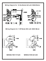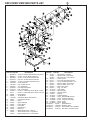
1
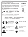
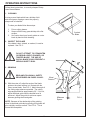
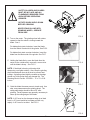
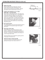
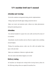
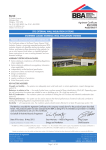
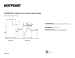
MODEL 440 & 450
ROTARY BLADE
GRINDER
OWNER'S
MANUAL
WARNING
You must thoroughly read and understand this manual
before operating the equipment, paying particular
attention to the Warning & Safety instructions.
1
44060 (2-05)
SAFETY INSTRUCTIONS
Safety Awareness Symbols are inserted into this manual to
alert you to possible Safety Hazards. Whenever you see these
symbols, follow their instructions.
The Caution Symbol identifies special instructions
or procedures which, if not strictly observed, could
result in damage to or destruction of equipment.
The Warning Symbol identifies special instructions or
procedures which, if not correctly followed, could result
in personal injury.
1. KEEP GUARDS IN PLACE and in working order. 12. MAINTAIN GRINDER WITH CARE. Follow
instructions in this manual for lubrication and
preventive maintenance.
2. REMOVE WRENCHES AND OTHER TOOLS.
3. KEEP WORK AREA CLEAN.
13. DISCONNECT POWER BEFORE SERVICING,
or when changing the grinding wheel.
4. DON'T USE IN DANGEROUS ENVIRONMENT.
Don't use grinder in damp or wet locations.
Machine is for indoor use only. Keep work area
well lit.
14. REDUCE THE RISK OF UNINTENTIONAL
STARTING. Make sure the switch is OFF before
plugging in the grinder.
5. KEEP ALL VISITORS AWAY. All visitors should
keep a safe distance from work area.
6. MAKE WORK AREA CHILD-PROOF with
padlocks or master switches.
15. USE RECOMMENDED ACCESSORIES. Consult
the manual for recommended accessories. Using
improper accessories may cause risk of personal
injury.
7. DON'T FORCE THE GRINDER. It will do
the job better and safer if used as specified in
this manual.
16. CHECK DAMAGED PARTS. A guard or other
part that is damaged or will not perform its
intended function, should be properly repaired
or replaced.
8. USE THE RIGHT TOOL. Don't force the grinder
or an attachment to do a job for which it was not
designed.
17. NEVER LEAVE GRINDER RUNNING
UNATTENDED. TURN POWER OFF. Do not
leave grinder until it comes to a complete stop.
9. WEAR PROPER APPAREL. Wear no loose
clothing, gloves, neckties, or jewelry which may
get caught in moving parts. Nonslip footwear is
recommended. Wear protective hair covering
to contain long hair.
18. KNOW YOUR EQUIPMENT. Read this manual
carefully. Learn its application and limitations
as well as specified potential hazards.
10. ALWAYS USE SAFETY GLASSES.
11. DO NOT OVERREACH. Keep proper footing
and balance at all times.
19. KEEP ALL SAFETY DECALS CLEAN AND
LEGIBLE. If safety decals become damaged
or illegible for any reason, replace immediately.
Refer to replacement parts illustrations in this
manual for the proper location and part
numbers of safety decals.
20. DO NOT OPERATE THE GRINDER WHEN
UNDER THE INFLUENCE OF DRUGS,
ALCOHOL, OR MEDICATION.
2
SAFETY INSTRUCTIONS
IMPROPER USE OF GRINDING WHEEL MAY CAUSE
BREAKAGE AND SERIOUS INJURY.
Grinding is a safe operation if the few basic rules listed below are followed. These
rules are based on material contained in the ANSI B7.1 Safety Code for "Use, Care
and Protection of Abrasive Wheels". For your safety, we suggest you benefit from
the experience of others and carefully follow these rules.
DO
1. DO always HANDLE AND STORE wheels in a
CAREFUL manner.
DON'T
1. DON'T use a cracked wheel or one that HAS
BEEN DROPPED or has become damaged.
2. DO VISUALLY INSPECT all wheels before
mounting for possible damage.
2. DON'T FORCE a wheel onto the machine OR
ALTER the size of the mounting hole - if
wheel won't fit the machine, get one that will.
3. DO CHECK MACHINE SPEED against the
established maximum safe operating speed
marked on wheel.
3. DON'T ever EXCEED MAXIMUM OPERATING
SPEED established for the wheel.
4. DO CHECK MOUNTING FLANGES for equal
and correct diameter.
4. DON'T use mounting flanges on which the
bearing surfaces ARE NOT CLEAN, FLAT
AND FREE OF BURRS.
5. DO USE MOUNTING BLOTTERS when
supplied with wheels.
5. DON'T TIGHTEN the mounting nut excessively.
6. DO be sure WORK REST is properly adjusted.
6. DON'T grind on the SIDE OF THE WHEEL
(see Safety Code B7.2 for exception).
7. DO always USE A SAFETY GUARD
COVERING at least one-half of the grinding wheel. 7. DON'T start the machine until the WHEEL
GUARD IS IN PLACE.
8. DO allow NEWLY MOUNTED WHEELS to run
at operating speed, with guard in place, for at
8. DON'T JAM work into the wheel.
least one minute before grinding.
9. DON'T STAND DIRECTLY IN FRONT of a
9. DO always WEAR SAFETY GLASSES or some
grinding wheel whenever a grinder is started.
type of eye protection when grinding.
10. DON'T FORCE GRINDING so that motor
10. DO TURN OFF COOLANT before stopping to avoid
slows noticeably or work gets hot.
creating an out-of-balance condition.
11. DO NOT Powerwash machine.
AVOID INHALATION OF DUST generated by grinding and cutting operations.
Exposure to dust may cause respiratory ailments. Use approved NIOSH or
MSHA respirators, safety glasses or face shields, and protective clothing.
Provide adequate ventilation to eliminate dust, or to maintain dust level below
the Threshold. Limit Value for nuisance dust as classified by OSHA.
3
SAFETY INSTRUCTIONS
This machine is intended for rotary blade grinding ONLY. Any use
other than this may cause personal injury and void the warranty.
To assure the quality and safety of your machine and to maintain the
warranty, you MUST use original equipment, manufacturers replacement parts and have any repair work done by a qualified professional.
ALL operators of this equipment must be thoroughly trained BEFORE
operating the equipment.
Do not use compressed air to clean grinding dust from the machine.
This dust can cause personal injury as well as damage to the grinder.
Machine is for indoor use only. Do NOT Powerwash machine.
MACHINE SPECIFICATIONS
Motor
440- 1/2 HP 115/230 Volt 50/60 Hz, 1 Phase
450- 1 HP 115/230 Volt 50/60 Hz, 1 Phase
Grinding Wheel
8" Diameter x 1.00" Wide - 24 Grit
Maximum Blade Length
Any Length
Sound Level
Greater than 85 Dba when operating.
DAILY MAINTENANCE
On a weekly basis, clean the rotary blade grinder by wiping it off.
On a weekly basis, inspect the grinder for loose fasteners or components.
Approximately every 40 hours of operation, remove the front blade support
base and grinding wheel. Then clean the inside of the grinder by wiping it off.
DO NOT USE COMPRESSED AIR TO
CLEAN GRINDING DUST FROM GRINDER.
UNPACK THE CARTON
Use care when unpacking. Open box, remove the contents and lay parts out on a table.
Check components against the Parts List on Page 11 to insure all parts were shipped and are in working order.
Inspect all items for shipping damage as they are removed from the shipping containers. If you find any
damage, notify the carrier's claims agent and do not proceed with unpacking until the damage has been
inspected by the agent. Refer also to the "Shipping Receiving Instructions" packed with this unit.
Install grinder in a dry indoor area with adequate lighting and ventilation.
4
WIRING INSTRUCTIONS
IMPORTANT GROUNDING INSTRUCTIONS
In case of a malfunction or breakdown, grounding reduces the risk of electrical
shock by providing a path of least resistance for electrical shock.
This Grinder has an electrical cord with an equipment grounding conductor
and a grounding plug. The plug must be plugged into a matching outlet that
is properly installed and grounded according to all local or other appropriate
electrical codes and ordinances.
115 Volt Model Only.
Plug the power cord
into standard
grounded receptacle
as shown:
Before plugging in the Grinder, make sure it will be connected to a supply
circuit protected by a properly-sized circuit breaker or fuse. 10 amp minimum
for 115V application.
DO NOT MODIFY THE PLUG PROVIDED WITH THE
MACHINE; IF IT WILL NOT FIT THE OUTLET, HAVE A
PROPER OUTLET AND CIRCUIT INSTALLED BY A
QUALIFIED ELECTRICIAN.
FIG. 1
Always provide a proper electrical ground for your machine. An improper
connection can cause a dangerous electrical shock. If you are unsure of the
proper electrical grounding procedure, contact a qualified electrician.
PLEASE TAKE SPECIAL NOTE OF THE FOLLOWING WARNING DECALS
LOCATED ON THE FRONT AND SIDES OF THE GRINDER.
Symbol for Read operators
manual, wear safety
glasses and disconnect
power before servicing.
Symbol to keep visitors a safe
distance away from the grinder.
Symbol identifying a panel, cover,
or area as having live electrical
components within.
Symbol for sharp object which will
cause serious injury.
Symbol for minimum safe rated
RPM of grinding wheel.
Symbol for hearing
protection required when
operating this machine.
5
OPERATING INSTRUCTIONS
Follow these instructions, to correctly sharpen Rotary
Lawn Mower Blades.
1. CLEANING
A rotary mower blade which has a buildup of dirt
and dried grass clippings cannot be properly
sharpened or balanced.
To clean your blade follow these steps:
1.
2.
3.
Put on safety glasses.
Scrape off the heavy grass buildup with a flat
scraper.
Use a wire wheel on a bench grinder or a wire
brush by hand to finish cleaning.
Cracked
Blade
FIG. 3
2. INSPECT THE BLADE
If the blade is bent, twisted, or cracked, it must be
replaced. See FIG. 3.
DO NOT ATTEMPT TO STRAIGHTEN
OR REPAIR A BENT, CRACKED, OR
TWISTED BLADE. THE USE OF
SUCH A BLADE COULD PRESENT A
SERIOUS SAFETY RISK.
3. GRINDING
READ AND FOLLOW ALL SAFETY
PROCEDURES ON PAGES 2 AND 3.
A. With the motor off, adjust the angle of the blade
guide so the wheel surface is in contact with the
rotary mower blade. See FIG. 5. Match the angle of
the cutting edge whenever possible. The cutting
edge angle should be approximately 30°. If it is not,
adjust the blade guide until the desired bevel is
achieved. Adjust the guide for minimum space
between grinding wheel and guide.
NOTE: Because of the relationship of the grinding
wheel to the blade guide during grinding, this grinder will
give a slightly concave surface. See FIG. 4. This is
normal and acceptable.
6
Wheel
Rotation
Minimum
Space
FIG. 4
SAFETY GLASSES AND GUARDS
MUST BE IN PLACE, AND ALL
FLAMEABLES REMOVED FROM
AREA BEFORE OPERATING
GRINDER.
ROTATE SPARK SHEILD DOWN
BEFORE GRINDING.
NEVER STAND IN LINE WITH
GRINDING WHEEL, OPERATE
FROM SIDE.
B. Turn on the motor. The grinding wheel will rotates
upward so that the wheel is turning toward the
blade. See 4.
FIG. 5
For blades that rotate clockwise, insert the blade
form the Wheel Guard side fo the grinder. See FIG 6
For blades that rotate counter-clockwise, insert the
blade from the Motor side of the grinder. See FIG 7
C. Holding the blade firmly, move the blade form the
center to the outside end in a smooth, even motion
until the blade is sharp. See FIG. 5.
FIG. 6
NOTE: If the blade is burning or blueing while
sharpening, use lighter strokes. Also, keep the grinding
wheel dressed and clean at all times to prevent heat
buildup. A grinding wheel slightly rounded on the edge
should run a little cooler than one dressed flat. The
Dressing Stick is Part No. 3702508 -- .75 x .75 x 3.00
inches.
FIG. 7
D. Grind the blade the same amount at each end. Use
slow, even passes across the grinding wheel. The
cutting edge angle should be about 30° after
grinding. Several passes are generally necessary to
clean up the cutting edge of the blade.
NOTE: A 30° bevel on the sharpened edge is an ideal
bevel--a 15° bevel would be too sharp and dull very
rapidly. A 45° bevel is too blunt. See FIG. 6.
FIG. 6
7
OPERATING INSTRUCTIONS (Continued)
E. REMOVING BURR
When the blade has been sharpened, stroke the
bottom of the cutting edge of the blade across a
deburring stone to remove any burr buildup. A flat file
may also be used to remove the burr. See FIG 9.
Bottom of
Cutting Edge
File
FIG. 9
F. BLADES WITH NONPARALLEL CUTTING
EDGE AND "S" STYLE BLADES
Rotary mower cutting blades with the cutting edge at an
angle to the body of the blade and "S" style blades must
be ground by holding the blade in the same way as
shown in FIG. 5 except the blade must be held at an
angle to the grinding wheel. This will permit the cutting
edge of the blade to be at a right angle to the grinding
wheel. By maintaining this angle and by moving the
blade from center to the outside end, a uniform cutting
edge will be ground.
G. MULCHING BLADES
For mulching blades, remove the blade guide and use the
rounded edge fo the adjustable support as the guide.
See FIG 10
H. BALANCING THE BLADE
Check the balance of the blade by placing it on the
balancer. The blade need not be perfectly balanced. If
the blade is held level and after releasing, the end drops
less than 1", the balance is satisfactory for ordinary use
on most rotary lawn mowers.
FIG. 10
Ordinarly the blade can be balanced by grinding just the
cutting edge of the heavier end.
I.
GUIDE FOR SMALL ENGINE VALVES
Use the hole located on the Wheel Guard Cover for
adjusting the length of valve stems. See FIG 11.
FIG. 11
8
Grinding Wheel Installation: When installing a new grinding wheel, it is important to follow the instructions provided by
the grinding wheel manufacturer. These instructions include
the following important points:
1. Always unplug the grinder before installing the new wheel.
2. Read and follow safety instructions on page 3.
3. Look at the threads on the wheel mounting adapter or hub.
They are left hand thread.
4. Remove the old wheel and install the new wheel. Make
sure the wheel mounting nut is tight, but not so tight as to
crack the wheel by crushing it between the flanges.
5. Make sure all guards are in place. Wear Safety Goggles.
Keep hands away from the wheel.
6. Start the grinder and check for excessive vibration. If you
have vibration, loosen the mounting nut and rotate the grinding wheel approximately 90 ° in relationship to the adapter
shaft. Tighten nut and reinstall guards, then retest for vibration. If necessary repeat rotation up to two more times. When
the wheel is mounted in the best position, it may also be
“dressed” for truth across the grinding surface.
7. If reasonable balance is not attained after trying four positions on the grinding adapter 90 degrees apart, the wheel
may not be properly balanced from the factory and should be
returned for replacement.
DRESSING THE GRINDING WHEEL
From time to time, the grinding wheel may build up steel particles in the grinding surface and will need to be dressed.
Each machine is supplied with one dressing stick. While the
grinder is running, hold this brick in the grinder the same way
you grind a blade. Move the brick back and forth until the
surface of the wheel is free of debris.
ALWAYS WEAR SAFETY GOGGLES WHEN
DRESSING A WHEEL.
9
Wiring Diagram for 1/2 Hp Model 440 with 09922 Motor
Wiring Diagram for 1 HP Model 450 with 09393 Motor
WIRING FOR 115 VAC
WIRING FOR 220 VAC
10
EXPLODED VIEW AND PARTS LIST
Dia. No. Part No.
Description
1 ...... B190834 .... 10-32 x 1/2 Button Head Socket Cap Screw
2 ...... B250801 .... 1/4-20 x 1/2 Hex Head Cap Screw
3 ...... B255601 .... 1/4-20 x 3 1/2 Hex Head Cap Screw
4 ...... B311201 .... 5/16-18 x 3/4 Hex Head Cap Screw
5 ...... C250460 .... 1/4-28 x 1/4 Socket Head Set Screw
6 ...... J253000 ..... 1/4-20 Wing Nut
7 ...... J311000 ..... 5/16-18 Hex Nut Full
8 ...... K251501 .... 1/4 Lockwasher
9 ...... K310001 .... 5/16 SAE Flat Washer
10 .... K311501 .... 5/16 Lockwasher
11 .... 3700077 .... 8" OD x 1" Wide-Grey Grind Wheel - 24 Grit
04711 ......... 8" OD x 1" Wide-Ruby Grind Wheel - 46 Grit
12 .... 09883 ......... On/Off Switch
13 .... 09922 ......... 1/2 HP Motor
3707590 .... 1HP Motor (Model 450 Grinder)
14 .... 40054 ......... Pivot Support Guide
15 .... 40056 ......... Guide
16 .... 40060 ......... Spark Deflector
17 .... 40062 ......... Frame Brace
18 .... 44052 ......... Pivot Plate
19 .... 44053 ......... Base Bottom
20 .... 44054 ......... Base Top
21 .... 44055 ......... Wheel Guard Cover - Maroon
44056 ......... Wheel Guard Cover - Light Green
44062 ......... Wheel Guard Cover - Forest Green
Dia. No.
Part No.
Description
22 .... 44057 ......... Wheel Guard - Maroon
44058 ......... Wheel Guard - Light Green
44063 ......... Wheel Guard - Forest Green
23 .... 80053 ......... 2-Prong Knob
24 .... 80141 ......... #10 x 5/8 Self Tapping Screw
26 .... 80164 ......... 5/8-11 Left Hand Hex Nut - Thin
27 .... 80234 ......... Motor to Switch Cord 1/2 HP
........ 80393 ......... Motor to Switch Cord 1 HP
28 .... 80235 ......... Main Power Cord
29 .... 80400 ......... Plug - Vac Hole
30 .... 3707273 .... Stain Relief
31 .... 3708514 .... Wheel Flange
32 .... 3708604 .... Warning Decal
33 .... 40063 ......... Adapter
34 .... 3709767 .... Rubber Bumper
35 .... 3708461 .... Decal - Wheel RPM Warning
36 .... 3708448 .... Decal - Electrical Warning
37 .... 3708606 .... Decal - Hearing Protections
38 .... 3708459 .... Decal - STOP
39 .... 3708460 .... Decal - START
Not Shown.......09700.........Blade Balancer
Not Shown.......3702508....Dressing Stick
Not Shown.......3707416....Strain Relief 1HP Cord/Motor
Not Shown.......3707155....Wire Nut 1 HP Motor Leads
11
THIS PAGE LEFT INTENTIONALLY BLANK FOR NOTE TAKING PURPOSES
12