1
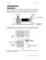
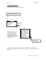
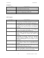
SYSTEM 5000
USER MANUAL
EMS GROUP
SYSTEM 5000
Table of Contents
Section
Page No
1 Introduction: - ...................................................................................................................... 3
1.1 Procedure: ........................................................................................................................... 3
1.2 Warnings and Cautions: ...................................................................................................... 3
2 User Control Levels: .......................................................................................................... 4
3 User Passwords: ................................................................................................................ 4
4 Controls and Displays: - .................................................................................................... 5
4.1 Controls Layout: .................................................................................................................. 5
5 Table of the Functions of the panel’s LED Indicators: - ................................................ 6
6 Control Keyswitch: ............................................................................................................. 7
6.1 OFF (Normal) Position Functionality: (Access Level 1) ...................................................... 7
6.2 ON Position Functionality: (Access Level 2) ....................................................................... 8
6.3 ISOLATED Position Functionality:....................................................................................... 9
7 User Option Functions:.................................................................................................... 10
8 Alphanumeric Display Indicators: - ................................................................................ 12
8.1 Non-Alarm Conditions: ...................................................................................................... 12
8.15 Fire Event: ....................................................................................................................... 12
8.2 Fire (Networked Device):................................................................................................... 13
8.25 Pre-Alarm:........................................................................................................................ 13
8.3 Tamper: ............................................................................................................................. 13
8.35 Fault Event:...................................................................................................................... 14
8.4 Fault : BT: MN:.................................................................................................................. 14
8.45 Fault : BT: ....................................................................................................................... 14
8.5 Fault : PR:.......................................................................................................................... 15
8.55 Fault : RI: ......................................................................................................................... 15
8.6 Fault : OL: .......................................................................................................................... 15
9 Step by Step Guidance: ................................................................................................... 16
9.1 Weekly Test Recommendations........................................................................................ 16
9.3 Enabling/Disabling Devices: .............................................................................................. 18
9.4 Enabling/Disabling Zones:................................................................................................. 19
9.5 Enabling/Disabling Brigade Relay: .................................................................................... 20
9.6 Printer Options: - ............................................................................................................... 20
9.7 Viewing the Event Log:...................................................................................................... 21
9.8 Enabling/Disabling Networked Devices:............................................................................ 22
9.9 Selecting Verify Delay Operation:...................................................................................... 23
10 Routine Tests: - .............................................................................................................. 24
10.1 Daily:................................................................................................................................ 24
10.2 Weekly: ............................................................................................................................ 24
10.3 Quarterly: ......................................................................................................................... 24
10.4 Annually: .......................................................................................................................... 24
10.5 Periodic Cleaning: ........................................................................................................ 24
11 Logbook: -....................................................................................................... 25
2
USER MANUAL, ISSUE 2.2 – 20/08/08
EMS GROUP
SYSTEM 5000
1 Introduction: -
This manual contains all of the information required for the use and operation of the
EMS System 5000. This manual is also written in a format that presumes that the
system has been correctly installed and commissioned. When using the system it is
important to follow this user manual at all times. Any questions on the system should
be put to the Installer/Maintainer.
1.1 Procedure:
In accordance with BS5839 Part 1:2002, written procedures must be established in
dealing with alarms for: -
Fire, Fault Warnings and the Disablement of any part of the System.
A responsible person should be appointed who ensures that all users are instructed
in the proper use of the system and are familiar with all associated procedures. The
nominated person shall also be responsible for liaising with the maintenance
company, on all matters relating to the maintenance of the system. One of the
associated procedures is to maintain an up to date logbook.
The logbook should include properly recorded events including all real and false
alarms. Also any testing or even temporary disablements should be noted. Infact, any
events affecting the system should be recorded. It should always be kept in a safe
place near the system, only with access by authorised personnel. A sample logbook
sheet is displayed in Section 11.
1.2 Warnings and Cautions:
These instructions contain the procedures to follow in order to operate the System
5000 control panel correctly. It is assumed that the user has been suitably trained
and is familiar with the relevant regulations.
All equipment is to be operated in accordance with the appropriate standards
applicable.
The material and instructions covered in this manual have been carefully checked for
accuracy and are presumed to be correct. However the manufacturer assumes no
responsibility for inaccuracies and reserves the right to modify and revise this
document without notice.
3
USER MANUAL, ISSUE 2.2 – 20/08/08
EMS GROUP
SYSTEM 5000
2 User Control Levels:
System 5000 has three different access levels. They are Levels 1, 2 & 3.
At User Level 1, all of the displays are completely functional, however the panel’s
control buttons and menu access features are inhibited.
At User Level 2, (Standard user access level via control keyswitch); all panel controls
are functional and the control panel’s menu is accessible. The requirement of the
Engineers PIN at the Engineers Config Menu, allows access to Level 3.
At User Level 3, all the panel’s controls are functional and the control panel’s menu is
fully accessible making full system configuration possible. User Level 3 is reached by
entering the Engineers PIN from Level 2. (Engineers Config Menu). User Level 3 is
intended for use by the System Installer/Maintenance Contractor.
3 User Passwords:
It is possible for the system to be programmed to allow a PIN number rather than the
control keyswitch to change from Access Level 1 to Level 2.
The system is not programmed, as standard with this feature as the control keyswitch
is normally used, however up to 99 User PINS can be assigned/changed at User
Level 3 by the Installer/Maintenance Contractor if required.
4
USER MANUAL, ISSUE 2.2 – 20/08/08
EMS GROUP
SYSTEM 5000
4 Controls and Displays: 4.1 Controls Layout:
The System 5000 control panel provides status information via the Display, Zone
Lamps and Status Lamps. The display and control of the panel’s functions is
achieved through two control panel sections. Figure 1, shows the display area which
includes Fire Zone Lamps, the Display itself and the “∆” and “∇” Scroll Buttons.
Scroll Buttons
Zone Lamps
Front Panel Lock
Figure 1 Zone Lamps and Display (model shown 5096)
20 Character 4Line Display
The System 5000 Panel is controlled by the use of the Control Keyswitch, a Numeric
Keypad and 3 Control Buttons. Fig 2 shows the Panel Controls and Indicator Lamps.
Fig 2
NOTE: The Status Lamps/Buttons & Control Keyswitch/Buttons operation is identical,
for all styles of control panel.
5
USER MANUAL, ISSUE 2.2 – 20/08/08
EMS GROUP
SYSTEM 5000
5 Table of the Functions of the panel’s LED Indicators: -
LED Indicator
Led Colour(s)
POWER
Control Panel Function
Indicates a good AC power supply.
ZONE FAULT
Illuminates, should one of the detection devices,
develop a fault condition.
GENERAL FAULT
Illuminates, should a fault condition occur within
a Control Panel or device.
ARE / BRIGADE FAULT
Illuminates should a communication fault occur
between the Alarm Routing equipment and the
Control Panel.
EARTH FAULT
Illuminates should an earth fault condition occur
on the system.
ARE / BRIGADE DISABLED
Illuminates when communication with the Alarm
Routing Equipment is disabled
TEST MODE
Illuminates whilst a device or detection zone is in
“TEST MODE”.
SOUNDER & OUTPUTS
DISABLED
Illuminates when an individual Sounder/Output
device or sounder zone is disabled.
FIRE
Illuminates when any device is in Fire Alarm
condition along with the fire zonal LED.
SOUNDER FAULT
Illuminates should a Sounder Based Device
indicates a fault condition.
SYSTEM FAULT
Illuminates should a fault become present with
the control panel itself.
DETECTOR/ZONE DISABLED
Illuminates when a Detection Device or Zone is
disabled.
Fig 3
6
USER MANUAL, ISSUE 2.2 – 20/08/08
EMS GROUP
SYSTEM 5000
6 Control Keyswitch:
The Control Keyswitch has three different positions. They are “OFF”, “ON” and
“ISOLATED”.
Each of their functions are explained on the following page: -
6.1 OFF (Normal) Position Functionality: (Access Level 1)
With the control keyswitch in the “OFF” position,
the panel is at Access Level 1. The key is
removable in this position and it is recommended
that the panel is left in this position with the
key removed. The following control options are
available: -
ISOLATED
DddddDD
OFF
ON
OFF
position
Scroll Buttons
Operational when multiple events are displayed to
enable each event to be viewed.
Reset/Led Test
Operates Status lamp test when system has no
events shown.
Silence Alarms
No operation.
Sound Alarms
No operation.
View Tests
nd
2 Feature
of key
View
Disablements
nd
2 Feature
of key
View Faults
nd
2 Feature
of key
View Fires
Status
Lamps,
(see fig 2)
System Menus
nd
2 Feature
of key
Displays any device/zone currently in test. This will
automatically timeout and return to the Front Screen
if left in this mode.
Displays any device/zone currently disabled. This
will automatically timeout and return to the front
screen if left in this mode.
Displays any device currently in fault condition. This
will automatically timeout and return to the front
screen if left in this mode.
Returns to view fire events if any of the other view
options used. This will automatically timeout and
return to the front screen if left in this mode.
N/A
Indicates the systems current status
N/A
No Operation
7
USER MANUAL, ISSUE 2.2 – 20/08/08
EMS GROUP
SYSTEM 5000
6.2 ON Position Functionality: (Access Level 2)
ISOLATED
OFF
ON
The Control Panel requires the control keyswitch
turned to the “ON” Position, enabling Access Level 2: -
The key may not be removed when in this position.
ON position
Scroll Buttons
Operational when multiple events are displayed to
enable each event to be viewed.
Reset/Led Test
This button has two functions. It is firstly used to
reset a Fire/Fault Event, after the “Silence Alarm”
button has been pressed and the Fire/Fault
condition has been cleared. It is secondly used to
test all of the Systems Status Lamps. This is
achieved by pressing the button when the Systems
Status is normal, i.e. no events displayed.
This button Silences the System’s Sounders and
internal buzzers. The panel will give an intermittent
beep every 10 – 15 seconds until the condition is
reset and will display Silence Alarms when pressed.
This key is used for activating the System’s
Sounders. The display will show Alarms Sounded
when pressed.
Silence Alarms
Sound Alarms
View Tests
nd
2 Feature
of key
View
Disablements
nd
2 Feature
of key
View Faults
nd
2 Feature
of key
View Fires
Status
Lamps,
(see fig 2)
System Menus
nd
2 Feature
of key
Displays any device/zone currently in test. This will
automatically timeout and return to the front screen
if left in this mode.
Displays any device/zone currently disabled. This
will automatically timeout and return to the front
screen if left in this mode.
Displays any device currently in fault condition. This
will automatically timeout and return to the front
screen if left in this mode.
Returns to view fire events if any of the other view
options used. This will automatically timeout and
return to the front screen if left in this mode.
N/A
Indicates the systems current status.
N/A
Options and further Fire system Options Menus are
now accessible by pressing the “0” Key. Details are
shown in Section 7.
8
USER MANUAL, ISSUE 2.2 – 20/08/08
EMS GROUP
SYSTEM 5000
6.3 ISOLATED Position Functionality:
The Control Panel requires the control keyswitch
ISOLATED
turned to the ISOLATED position. Access Level 2 is
accessible with the same features as detailed
OFF
previously and all control buttons are operational.
Plant Shutdown equipment can be disabled
through this function as a pre selected
Sounder Group can be disabled. This is normally
used for isolating Plant Equipment whilst carrying out
weekly tests. However, this is a programmable
feature and can be configured by the
installer/maintenance contractor if required.
ON
ISOLATED
position
Scroll Buttons
Operational when multiple events are displayed to
enable each event to be viewed.
Reset/Led Test
This button has two functions. It is firstly used to
reset a Fire/Fault Event, after the “Silence Alarm”
button has been pressed and the Fire/Fault
Condition has been cleared. It is secondly used to
test all of the Systems Status Lamps. This is
achieved by pressing the button when the Systems
Status is normal, i.e. no events displayed.
This button Silences the System’s Sounders and
internal buzzers. The panel will give an intermittent
beep every 10 – 15 seconds until the condition is
reset and will display Silence Alarms when pressed.
This key is used for activating the System’s
Sounders. The display will show Alarms Sounded
when pressed.
Silence Alarms
Sound Alarms
nd
View Tests
2 Feature
of key
View
Disablements
2 Feature
of key
View Faults
2 Feature
of key
View Fires
2 Feature
of key
Status
Lamps,
(see fig 2)
System Menus
Isolated Lamp
nd
Displays any device/zone currently in test. This will
automatically timeout and return to the front screen
if left in this mode.
Displays any device/zone currently disabled. This
will automatically timeout and return to the front
screen if left in this mode.
nd
Displays any device currently in fault condition. This
will automatically timeout and return to the front
screen if left in this mode.
nd
Returns to view fire events if any of the other view
options used. This will automatically timeout and
return to the Front screen if left in this mode.
N/A
Indicates the systems current status
N/A
Options and further Fire system Options Menus are
now accessible by pressing the “0” Key. Details are
shown in Section 7.
Sounder group disabled by key position. This is a
programmable feature normally used for isolating
plant equipment on a weekly test and is configured
by the Installer/Maintenance contractor.
ISOLATED
9
USER MANUAL, ISSUE 2.2 – 20/08/08
EMS GROUP
SYSTEM 5000
7 User Option Functions:
The following Level 2 functions are available:
Put the Control Keyswitch into the
“ON” Position & Press the “0” Key.
(A)
Options
Passwords
Time and Date
Logging
Fire System Opts
Press the
YES” key
(B)
Fire System
Dev. Disable/Test
Net. Disable/Test
Det Zone Dis/Test
Alarm Zone Disable
ARE Disable
System Mode
Engineers Config
Printer Options
Note: If events are
displayed on the System.
Pressing the “0” Key with
the Control Keyswitch in
the “ON” Position, will take
system direct to the Fire
System Menu.
Access Level 3
via PIN entry
To scroll through the menus, use the “∆” and “∇” scroll buttons. To enter a menu
position the required option between the > and < cursors on the screen and press the
“YES” key.
10
USER MANUAL, ISSUE 2.2 – 20/08/08
EMS GROUP
SYSTEM 5000
(A) Options:
FUNCTION
Passwords
Time and Date
Logging
Fire System Options
DESCRIPTION
Contains 7 sub menus. This allows the option to change,
edit and delete PIN numbers if used.
Gives the option to set and view the Time and Date.
Enables you to view the entire log of events, (up to 1000
events), or to view the log at a certain date.
Allows access to (B) Fire System.
(B) Fire System:
FUNCTION
Dev. Disable/Test
Net. Disable/Test
Det Zone Dis/Test
Alarm Zone Disable
ARE Disable
System Mode
Engineers Config
Printer Options
DESCRIPTION
This option enables an individual device that forms part of
the fire system to be Disabled, Activated or put into Test.
The status lamps will illuminate/extinguish as appropriate.
This option enables the user to control individual devices
that are logged onto other control panel’s on the Networked
Fire System. Such as a smoke detector or call point to be
changed from their normal active status, to be disabled or
put into test.
This option allows the Detection Zone to be viewed and
altered. The zone can be either Active, Test or Disable. If
any zones on the system are disabled or in test mode the
relevant LED Indicators will light to indicate this.
This option allows the disablement of groups of sounders
within the system. The Alarm Zone can be either Enabled or
Disabled. If Disabled the relevant LED indicator will
illuminate.
This option allows connection to the Fire Brigade via the
Brigade Relay to be disabled. Therefore any subsequent
fire activation’s will not operate this relay. The panel
operation, although unaffected, will display the text
“ARE/BRIGADE DISABLED” to ensure the system is not left
in this mode.
This option allows enablement of up to eight different
system modes of operation. These are pre-programmed and
can be changed if required by the Installer/Maintenance
Contractor.
This option when entered prompts for a PIN number to be
entered to Allow access to Level 3. This menu is for
Installer/Maintenance Contractor use only.
This option allows the Printer, when fitted, to be both
“Enabled” and “Disabled”. When “Enabled” and the option is
set to ALL, every Event is printed out. This option can also
be set to FIRE, which will then only print Fire Events.
11
USER MANUAL, ISSUE 2.2 – 20/08/08
EMS GROUP
SYSTEM 5000
8 Alphanumeric Display Indicators: -
There are two different types of Displays. There is the Vacuum Fluorescent Display
(VFD) type, which displays up to 80 characters, on a 4-line display. This is standard
for 24 and 96 zone models.
A Liquid Crystal Display (LCD) type, is also available and is standard for 12 and 4
zone models.
There are different types of conditions that are shown on the display, to suit different
circumstances. Below are some display indication screen shots: -
8.1 Non-Alarm Conditions:
Under Non-Alarm Conditions, the display should show: -
Status Normal
25/02/04
12:00
The Green “Power” LED should also be illuminated.
8.15 Fire Event:
When a Fire event occurs the text on the display changes, to show: -
01 FIRE ALARM TOT 01
CP GROUND FLOOR
ENTRANCE LOBBY
ZONE 01
DEVICE 005
The above shows that Device 5 has generated a Fire event in Zone 1.
12
USER MANUAL, ISSUE 2.2 – 20/08/08
EMS GROUP
SYSTEM 5000
8.2 Fire (Networked Device):
When a device on a Networked Control Panel has activated a Fire Alarm, the
following alarm screen will be shown: -
01 FIRE ALARM TOT 01
CP THIRD FLOOR
GAMES ROOM
ZONE 01 P:04 DEV 027
The above display shows that a Fire Alarm has been generated from Device 27, in
Zone 1 on Panel 4.
8.25 Pre-Alarm:
When a Pre-Alarm event occurs the text on the display changes to show: -
01 PRE-ALARM TOT 01
SS FIRST FLOOR
MAIN BEDROOM
ZONE 03 DEVICE 027
The above display shows that Device 27 has entered a Pre-Alarm event, in Zone 3.
8.3 Tamper:
When a device generates a Tamper Alarm, the display will change to show: -
01 TAMPER
TOT 01
CP GROUND FLOOR
ENTRANCE LOBBY
ZONE 01
DEVICE 005
The above shows that Device 5 has generated a Tamper Alarm in Zone 1.
13
USER MANUAL, ISSUE 2.2 – 20/08/08
EMS GROUP
SYSTEM 5000
8.35 Fault Event:
When a Fault Event occurs the text on the display changes to show: -
01 FAULT
TOT 01
RS SECOND FLOOR
MAIN CORRIDOR
ZONE 04
DEVICE 056
The above display, tells us that device 56, has entered a Fault condition in Zone 4.
8.4 Fault : MN:
In the instance of a system mains failure, the controller will switch into battery safe
mode. This will turn the display completely off, and the “Power” LED will extinguish.
Pressing any key on the panel will re-activate the display and the following fault
screen will be shown: -
01 FAULT
TOT 01
CONTROL PANEL
FAULT : MN
12:00
FAULT MN represents the controller has had a mains failure.
The “CIE Fault” LED will also illuminate when the above screen is displayed.
8.45 Fault : BT:
This fault can be displayed for a number of reasons. There maybe no batteries
present in the unit. Secondly the batteries may not be charging. Thirdly the battery
voltage may be low. The battery not charging and low voltage readings would be
displayed after the daily check at midday. The fault would be displayed immediately
when batteries are not present. For any of these instances the following screen
would be displayed: -
01 FAULT
TOT 01
CONTROL PANEL
FAULT :BT
14
12:00
USER MANUAL, ISSUE 2.2 – 20/08/08
EMS GROUP
SYSTEM 5000
8.5 Fault : PR:
Whenever the control panel’s internal processor is reset, (including initial power up),
the following fault screen will be shown: -
01 FAULT
TOT 01
CONTROL PANEL
FAULT :PR
12:00
8.55 Fault : RI:
Radio signal levels can vary due to the surrounding local environment. The following
screen shows that the controller is receiving unknown radio signals above an
acceptable level: -
01 FAULT
TOT 01
CONTROL PANEL
FAULT : RI
12:00
The Fault RI represents that the panel is receiving Radio Interference.
8.6 Fault : OL:
This fault shows that a controller is currently Off Line on either a Hardwired or radio
networked system. This indicates the Control Panel is no longer communicating with
the Network System. If this has taken place the following fault screen will be shown:-
01 FAULT
TOT 01
CONTROL PANEL
FAULT :OL
15
12:00
USER MANUAL, ISSUE 2.2 – 20/08/08
EMS GROUP
SYSTEM 5000
9 Step by Step Guidance:
9.1 Weekly Test Recommendations.
A manual callpoint should be tested on the system each week. It is recommended
that the test be carried out at the same time each week with any poor audibility
instances reported.
A different manual callpoint should be tested each week to ensure that all callpoints
are tested over time.
The results of the test and the callpoints used should be recorded in the logbook. If
the system is connected to an alarm receiving centre they should be informed before
and after the test and the fire alarm signal confirmed.
Carrying Out the Test.
If applicable contact the alarm receiving centre to inform them that a test is about
to be carried out.
Turn the key on the control panel to the ISOLATED position.
I SOLATED
OFF ON
Wait 15 seconds.
15 seconds
Activate a manual callpoint by inserting the test key.
Fire alarm with text and zonal indication will now be displayed on the control panel
along with sounder operation.
Wait for 30 seconds.
30
seconds
SILENCE
Press the silence alarms button. (The time period shown is an average time and
maybe reduced if required, dependant on the size of the system).
Press the Reset alarms button to reset the fire alarm event.
ALARMS
RESET/
LED TEST
I SOLATED
The display should return to normal. The key should be returned to the OFF
position and removed from the control panel.
If applicable contact the alarm receiving centre and confirm that the test has been
completed and verify signal received.
The test is now complete and the logbook should now be updated.
16
USER MANUAL, ISSUE 2.2 – 20/08/08
OFF ON
EMS GROUP
SYSTEM 5000
9.2 Setting the Time and Date: -
To change the time and date, turn the control keyswitch into the “ON” position. Now
press the “0” Key. Press the “∇” button once until “> Time and Date <”. Is displayed.
Press the “YES” key and you will enter the “| ** Date/Time **|” Menu.
To set the time, press the “YES” key again, and enter the time in 24hr, hh:mm format.
Then press the “YES” key to confirm. Press the “NO” key twice to return to the main
display.
Please Enter New
Time > 12:00
Hours : Minutes
Yes = Finish
To enter the date, (from the Date/Time Menu), press the “∇” button twice until
highlighting “>Set the Date <” then press the “YES” key. Now enter the date in
dd:mm:yy format and then press the “YES” key to confirm. Once confirmed, press the
“NO” key twice to return to the main display.
Please Enter Today’s
Date > 24 / 02 / 04
Day / Month / Year
Yes = Finish
12:00
NOTE: On Multi-panel systems, it is only necessary to alter the time and date on the
Master Panel and this will automatically pass the information to other panel’s on the
system.
17
USER MANUAL, ISSUE 2.2 – 20/08/08
EMS GROUP
SYSTEM 5000
9.3 Enabling/Disabling Devices:
To Enable/Disable a device from the main screen:
With the control keyswitch in the “ON” Position, press the “0” key, then scroll down to
last option, “Fire System Options”.
Press the “YES” key. Now, whilst highlighting the “>Dev. Disable/Test<” option, press
the “YES” key again.
Now press the “0” key and enter the desired device number and press the “YES” key.
The display will show: -
| **
Device Status *
|
> Number is :
006 <
| Status
is : Active |
Yes = Select
12:00
| Number is :
006 |
> Status
is :Disable <
| Det .
zone :
02 |
Yes = Select
12:00
Note: If an event is displayed the Fire System Menu is immediately accessed by
turning the Key into the “ON” Position and pressing the “0” Key.
Then press the “∇” button to highlight “>Status is :Active <”, and scroll through the
different status types by pressing the “YES” key until desired option has been found,
then press the “NO” key three times, to return to the main display.
Whilst a device is disabled, the “DETECTOR/ZONE DISABLED” LED Indicator will
illuminate. When the devices are enabled the LED Indicator will extinguish, unless
any detection zones are disabled.
18
USER MANUAL, ISSUE 2.2 – 20/08/08
EMS GROUP
SYSTEM 5000
9.4 Enabling/Disabling Zones:
To Enable/Disable a zone from the main screen:
With the control keyswitch in the “ON” position, press the “0” key, then scroll down,
by pressing the “∇” button to last option, “>Fire System Options<”.
Press the “YES” key. Now, press the “∇” button until highlighting
“>Det Zone Dis/Test<”.
Now press the “YES” key again. Now press the “0” key and enter the desired Zone
Number and press the “YES” key.
| ** Zone Status **
|
> Zone
is : 01
<
| Status
: ACTIVE |
Yes = Select
12:00
| Zone
is : 01
|
> Status
: DISABLE <
| ^^^^^^^^^^^^^^^^^^ |
Yes = Select
12:00
Press the “∇” button and scroll through the different status types by pressing the
“YES” key until desired option has been found, then press the “YES” Key.
Now press the “NO” key until to return to the main display.
Whilst a zone is disabled, the “DETECTOR/ZONE DISABLED” LED Indicator will
light.
When the zones are enabled the LED Indicator will extinguish, unless a Detector is
Disabled.
19
USER MANUAL, ISSUE 2.2 – 20/08/08
EMS GROUP
SYSTEM 5000
9.5 Enabling/Disabling Brigade Relay:
To Enable or Disable the Brigade Relay turn the control keyswitch to the “ON”
Position and Press the “0” key. Scroll down to the bottom of the Options Menu using
the “∇” button, until highlighting “>Fire System Options<”. Press the “YES” key. Press
the “∇” button until highlighting the “>ARE Disable <” option. Press the “YES” key.
Then press the “YES” key again to change from “ENABLED” TO “DISABLED”
alternately.
ARE / Brigade DISABLED
Push YES to change
Push NO to escape
Push YES / NO
ARE / Brigade ENABLED
Push YES to change
Push NO to escape
Push YES / NO
Then having selected the desired option, press the “NO” key three times to return to
the main display.
9.6 Printer Options: To enter the Printer options from the main display, put the control keyswitch into the
“ON” position. Press the “0” key. Now using the “∇” button, scroll down to the last
option, “>Fire System Options<”. Now press the “YES” key. Then scroll down,
pressing the “∇” button to the last option, “>Print Options <”. Now, press the “YES”
key.
Now having reached the “Print Options”, press the “YES” key to turn the Printer “ON”
or “OFF”. Whilst the printer is set to “ON”, press the “∇” button, then press the “YES”
key to change the print event between “FIRE” or “ALL”.
| * Print Options *
|
> Printer is
ON
<
| Print Events ALL
|
Yes = Select
12:00
| * Print Options *
|
| Printer is
ON
|
> Print Events FIRE
<
Yes = Select
12:00
This depends on whether the printer is required to print All events or just any Fire
Events. Once suitably configured, press the “NO” key three times to return to the
main display.
20
USER MANUAL, ISSUE 2.2 – 20/08/08
EMS GROUP
SYSTEM 5000
9.7 Viewing the Event Log:
Turn the control keyswitch to the “ON” position and press “0” key. The screen will
now display:
| * * * Options * * * *
|
> Passwords
<
| Time and Date
|
Yes = Select
Time
Press the ∇ key twice until the screen displays “ >Logging< ”. Press the “YES” key
and the screen will change to highlight “ >View Log At Date< ”. Now press the “YES”
key and the screen will now display:
Enter the date to
View:
/
/
Yes = Finish
Time
Enter the required date to view in dd/mm/yy Format, (e.g.28/05/03) then press the
Yes key and the screen will now display:
---------------On 28/05/03 At 00:00
New Day of 28/05/03
Yes = Select
Time
By pressing the, ∆ and ∇ scroll buttons, the log for the date selected can be viewed.
All fire and fault events are listed in date and time order. Pressing the “5” key will take
you to the oldest event, whilst pressing the “8” key will take you to the most recent
event.
When finished, press the “NO” key three times until the screen returns to the main
display. Turn the control keyswitch to the off Position and the screen will now indicate
that the Status is Normal.
21
USER MANUAL, ISSUE 2.2 – 20/08/08
EMS GROUP
SYSTEM 5000
9.8 Enabling/Disabling Networked Devices:
Turn the control keyswitch to the “ON” position. Press “0” key to enter the “Options”
Menu. Press the ∇ key three times until the screen displays:” >Fire System Opts<”.
Press the “YES” key and the screen will change to highlight “>Dev.Disable/Test<”.
Press ∇ key once to highlight the option “> Net. Disable /Test<” and press the “YES”
key and the screen will now display:
| * Network Status * |
> Panel Type : PAN
<
| Panel
: 00
|
Yes = Select
Time
NOTE: It is important the correct Panel type is highlighted.
PAN = Hardwired Panels. NET = Radio Network Panels.
This information can be provided by installer/Maintenance Contractor if required.
Press “YES” key once to change the Panel type to the required setting.
Press the ∇ key one time and the screen will now be highlighting, ”>Panel : 00<”.
Press the “YES” key to change the panel number until the desired panel number is
shown: Press ∇ key one time and the screen will change to highlight,
” >Device : 00<”. Press “0” key and the screen will now display:
Enter Device
(Number 1 - 256)
Number > _
Yes = Finish
Time
Enter the device number that you want to Enable/Disable e.g. 007, then press “YES”
key and screen will now display:
| Panel
: 04
|
>Device
: 007
<
| Status
: Active |
Yes = Select
Time
Press the ∇ key one time and the screen will change to highlight
“>Status : Active<”. Press “YES” key once to change the Status of the device to
Active or Disabled as desired. Now press the ∇ key once and whilst highlighting
“>Transmit Event<”, press the “YES” key to transmit the event. The screen will state
that the change has been made.
Press “NO” key four times until the screen returns to the main display. Turn the
control keyswitch to the “OFF” Position and the screen will now indicate that the
Status is Normal.
22
USER MANUAL, ISSUE 2.2 – 20/08/08
EMS GROUP
SYSTEM 5000
9.9 Selecting Verify Delay Operation:
Delay Mode Operation
The panel can be configured to operate in a delayed mode either manually or via a
secondary keyswitch.
When selected, alarm signals received from a detector will generate a fire alarm
message on the panel but delay the operation of the sounders. The panel will initiate
a full fire alarm condition if no action is taken on this warning within a specified
period.
The use of visual delay mode must be configured at level 3, by an
installer/maintenance contractor, before it is available for use at level 2.
The visual delay mode can be configured to operate when manually selected at the
panel, via a secondary keyswitch or automatically via a separate timer. The
maximum time allowed for acknowledging the timer can be programmed in intervals
of one second.
Whilst the visual delay mode Function is active the front screen will display
VERIFY DELAY MODE.
Standard Delay Operation
When a fire alarm condition is detected in this mode, the internal buzzer will sound.
The device location will be shown on the display along with a warning that the panel
has entered delayed alarm.
If the warning is not acknowledged, by pressing the “SILENCE ALARM” button,
within the time allowed, then a full fire alarm condition will be raised and the sounders
will activate.
Pressing the “SILENCE ALARM” button within the time allowed will cause the
timer to stop.
A secondary device activating within the timer or a manual callpoint activation will
immediately generate a fire alarm condition.
23
USER MANUAL, ISSUE 2.2 – 20/08/08
EMS GROUP
SYSTEM 5000
10 Routine Tests: -
In order to ensure that the system is fully operational and to ensure compliance with
B.S.5839 Part1: 2002, the following routine tests to the system should be carried out.
Note: Records should be maintained of all testing activities, on the enclosed
Logbook Data Table.
10.1 Daily:
Check the control panel to ensure that it indicates normal operation. (Status should
be Normal). If any fault is indicated, check that it has been recorded in the logbook
event data table and that the appropriate actions have been taken. E.g. informing the
maintenance company.
10.2 Weekly:
Test at least one detector or call point, to confirm the operation of the panel and the
audible alarms. A different zone should be tested each week and, if possible, a
different device. Record the outcomes of the testing.
The zone and the device number should be noted into the Control Panel logbook.
Any malfunctions must be reported. The “LED TEST” key should be pressed to
ensure that all of the LED Indicators are in full working order.
10.3 Quarterly:
The person nominated with the responsibility for the system, should ensure that a
competent person checks the system every 3 months. The competent person shall: i) Check the Logbook Event Data Table entries, and the results of any action taken.
ii) Check the standby batteries and the charger voltage.
iii) Test at least one device in each zone, to verify the functionality of the Control
Panel.
iv) Check the operation of the audible alarms and any link to a remote manned
centre, central station, etc.
v) Carryout a visual inspection of the system to check for alterations or obstructions.
vi) Issue a Certificate of Testing.
10.4 Annually:
The responsible person should ensure that, in addition to the quarterly checks, each
device on the system is tested and that a visual inspection is made of the cable
fittings and equipment.
10.5 Periodic Cleaning:
The Control Panel and devices should be periodically cleaned, by wiping with a soft
damp cloth.
However, the use of solvents on the Control Panel or Devices is not recommended.
24
USER MANUAL, ISSUE 2.2 – 20/08/08
EMS GROUP
SYSTEM 5000
11 Logbook: One or more individuals should be appointed, to maintain a Logbook and to oversee
all entries and record all events resulting from or affecting the system.
The Logbook should be kept in a safe place, closely situated to the Control Panel. It
should only be accessible to those authorised persons
The names of the responsible appointed persons should be recorded on the
Reference Data Table below.
All events including real and false Fire Events, Faults, Pre-Alarm Warnings, Tests,
temporary Disablements should be properly recorded.
Service visits should also be recorded. Such recordings should be accompanied with
brief notes of any work that has been or is to be carried out.
Such Reference Data should be detailed in the sample below: -
Site Name and Address:
Site Telephone No:
Responsible Person(s): -
Date:
Date:
Date:
System Installer:
This System is Maintained by:
Until:
Maintenance Companies Contact Telephone No:
Reference Data Table:
On the next page, is a sample page of the Logbook. This can be photocopied to
produce a suitable Logbook:
25
USER MANUAL, ISSUE 2.2 – 20/08/08
EMS GROUP
Date
Time
SYSTEM 5000
Event/Dev No/Zone
No
26
Action Taken
Date
Completed
USER MANUAL, ISSUE 2.2 – 20/08/08
Initials
EMS GROUP
SYSTEM 5000
27
USER MANUAL, ISSUE 2.2 – 20/08/08
EMS GROUP
SYSTEM 5000
EMS Group Head Office
Technology House
Sea Street
Herne Bay
Kent CT6 8JZ
England
Dealer Information
Tel: +44 (0) 8712 710804
Fax: +44 (0) 1227 369679
Email: [email protected]
www.emsgroup.co.uk
Calls are charged at up to 10p (incl. VAT) per minute, on the BT Network. Mobile and other Network costs may vary.
The information contained within this literature is correct at time of publishing. The EMS Group reserves the right to change any
information regarding products as part of its continual development enhancing new technology and reliability. The EMS Group advises
that any product literature issue numbers are checked with its head office prior to any formal specifications being written.
28
USER MANUAL, ISSUE 2.2 – 20/08/08