1
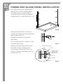
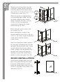
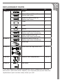
48" x 32" Corner
shower unit
Installation Guide
and User Manual
Model#: 1JPS009OOO
ATTENTION:
1.
2.
3.
Your installation must comply with all local plumbing
building codes. Have a qualified tradesman do and/or approve
your plumbing installation.
Always wear safety goggles and gloves in order to avoid
personal injury.
Please read and save this guide before using this product.
Store the guide in a safe place so you will know where it is
when you want to refer to it.
IMPORTANT
2
Carefully check the unit prior to installation to ensure there is no
damage. Do not dispose of any packaging until you are satisfied with
this product.
If you have any problems with this product or there are missing
or damaged parts, please call toll free:
1-800-459-4409
DO NOT RETURN THE UNIT TO THE PLACE OF PURCHASE
BEFORE CALLING THE TOLL FREE NUMBER ABOVE.
PRODUCT FEATURES
Our shower units are manufactured using top quality cast acrylic and
are designed for years of comfort and enjoyment.
•
Each unit is formed using 3 mm (0.5 in) thick cast acrylic that
provides an attractive, easy to clean and maintain, high gloss
surface.
•
The acrylic surface resists chipping, staining, mold and mildew.
•
Heavy duty construction / Reinforced with fire retardant fiberglass /
Engineered base with leveling feet for easy installation.
•
Tempered safety glass.
•
Powder coated aluminum frames provide a very durable finish.
BEFORE YOU START
1. Inspect your unit before proceeding. Check surface for any flaws or
damage. Your unit has been manufactured with a cast acrylic sheet
providing an extremely durable surface. Once you unpack your unit,
check for chips, scratches, cracks, dents or scuff marks. If you
notice any damage, do not install. Talk to your retailer where the
unit was purchased.
2. Please read instructions carefully and keep for future reference.
3. Protect the entire surface during installation.
4. Make sure the floor structure is capable of supporting 45.5 kgs
(100 lbs) per square foot.
5. In all cases the total weight of the unit MUST rest on the floor. No
weight should be supported by the skirt or the tiling flange.
6. All holes drilled into the unit must be done from the inside (finished
surface) towards the outside (rough surface) and caulked very
carefully to form a water-tight barrier.
7. Your installation must comply with all local plumbing codes. Have a
qualified tradesman do and/or approve your plumbing installation.
WARNING: Always wear safety goggles and gloves in order to
avoid any personal injuries.
To complete the installation you will need:
Pipe and fittings according to your
installation requirements
Construction adhesive
Small can of ABS pipe glue
Mortar or plaster
Silicone caulking
Tools Required:
Hammer
Pencil
Utility knife
Phillips
screwdriver
Rubber mallet
Measuring tape
Carpenters
level
Wood shims
Jig saw
1/8" drill bit
Large flat
screwdriver
Drill
Carpenter’s
square
3
CONTENTS
4
Large glass panel (1)
Small glass panel (1)
Glass door panel (1)
Shower base (1)
Side frame (2)
Wall frame (2)
Aluminum
frame (1)
Long aluminum
track (1 top,
1 bottom)
Short aluminum
track (1 top,
1 bottom)
Aluminum magnet
frame (1)
Handle (1)
Top corner
piece (1)
Top corner
cover (1)
Bottom corner
piece (1)
Bottom corner
cover (1)
Wall anchor (6)
Stainless steel
screws 3.9 mm x
25 mm (14)
Cap A (12)
Stainless steel
screws 3.9 mm x
13 mm (16)
Stainless steel
countersunk
screws 3.9 mm x
13 mm (2)
Stainless steel
countersunk screw
5 mm x 25 mm (1)
Magnet strip (1)
Triangular rubber
gasket (4)
Stainless Steel
countersunk
screws 3.9 mm x
25 mm (5)
Washers (12)
Double wheel
rollers (2)
Single wheel
rollers (2)
Cap B (2)
Anchor clips (5)
INSTALLATION INSTRUCTIONS
BASE INSTALLATION:
1. If installing in a location where
drywall has already been set up,
confirm that it is water resistant
drywall. Once location of shower
enclosure and base has been
established and drywall has been
confirmed to be water resistant,
mark the walls as per Fig.1. If
drywall is not the appropriate type,
remove from the total area where
the shower enclosure is to be
installed and skip the next step.
2. Cut drywall leaving the
studs exposed.
121.5 cm
(48 in)
81.3 cm
(32 in)
17.8 cm
(7 in)
1.5 in
3. Mark position of the drain as
per Fig. 2. Cut floor with jig saw
approximately 12.7 cm (5 in)
total diameter.
5
Fig. 1
3.8 cm
40.6 cm
(16 in)
12.7 cm
(5 in)
4. Put base in place and begin
leveling by placing carpenter’s
level, as per Fig 3.
5. Shim the fixed legs as required for
leveling so the skirt of the base is
6.35 mm (0.25 in) above the floor
as per Fig. 4. Make sure that all
legs make contact with the floor
and shims. Check level again and
that all legs make contact with
the floor.
Studs
Drywall
Wall Covering
or Tiles
6.35 mm
(0.25 in) min
5.1 cm
(2 in) pipe
23.5 cm
(9.25 in)
Fig. 2
Fig. 3
Raised flange
Fixed Legs
6.35 mm (0.25 in)
Fig. 4
6
6. Remove base. Remove strainer
and wrench (leave ring and rubber
collar in place) from the drain
assembly and install drain, as
shown in Fig. 5. Apply silicone on
the acrylic drain area where the
fitting will make contact. Do not
over-tighten nut as drain body may
warp or break.
Strainer
Wrench
Ring
Rubber collar
Drain body
7. Secure vertical drain pipe in place,
with 3.8 cm (1.5 in) exposed
above floor level (see Fig. 6).
Rubber washer
Paper washer
8. Shower base must be set in a bed
of mortar. Lay the mortar in the
areas where the metallic frame is
located. 5.1 cm (2 in) of clearance
should be left around the drain
pipe hole.
9. Lubricate the exposed pipe and
the inside rubber collar of drain
with soapy water. Set the base
into place making sure the pipe
fits into the collar and that the
mortar squeezes up around the
frame as shown in Fig. 7. Check
level and be sure that the unit is
resting very firmly on the floor.
Locking nut
Fig. 5
1.5 in
Wall Covering
or Tiles
Clips
5.1 cm
(2 in) pipe
40.6 cm
(16 in)
12.7 cm
(5 in)
23.5 cm
(9.25 in)
Fig. 6
Studs
Drywall
3.8 cm
Mortar
6.35 mm
(0.25 in) min
Raised flange
Fig. 7
10.Check that the drain pipe fits
properly in the drain. Secure
anchoring clips using 3.9 mm x
25 mm (0.5 in x 1 in) countersunk
stainless steel screws as shown in
Fig. 8.
11.To ensure a watertight seal
between the collar and the pipe,
tighten the drain ring using the
wrench provided and a large flat
screwdriver (see Fig. 9). Do not
over-tighten as drain may warp or
crack. Insert strainer into position.
7
Fig. 8
12.Replace water resistant drywall
leaving a 6.35 mm (0.25 in) gap
between the top flange and the
drywall. Run a bead of silicone
caulking around the joint between
the top flange and the drywall.
13.Run a bead of silicone between
the floor and the shower enclosure.
Install flooring to 3.2 mm (0.125 in) 1
from the shower enclosure. Run a
bead of silicone between flooring
and shower enclosure.
14.Replace or install new wall
covering (tiles, marble, etc.) so
that the wall covering is 3.2 mm
(0.125 in) over the deck of the
shower base covering all the
clips and drywall opening. Run a
bead of silicone between the wall
covering and the shower base.
2
Fig. 9
Frame and glass panel installation
8
Put wall frame on the shower base
with 20 mm (0.79 in) distance from
the edge of base. Using a pencil,
mark the hole positions on the wall
through holes on wall frame (Fig. 10).
20mm
20mm
Fig. 10
Remove the wall frame, drill holes
into the wall where you indicated with
pencil marks (Fig. 11).
Repeat procedure on the other
wall frame.
Put six wall anchors in to each of the
six drilled wall holes.
Replace the wall frame and secure
with wall using six washers and
six 3.9 mm x 25 mm (0.15 in x 1 in)
screws. Cover screw heads with six
A caps (Fig. 12).
Fig. 11
Anchors 6 mm (0.24 in)
washer
3.9 mm x 25 mm
(0.15 in x 1 in)
stainless self
tapping screw
cap
wall frame
drill hole
Fig. 12
Attach side frames to the top and
bottom tracks as shown, using eight
3.9 mm x 25 mm (0.15 in x 1 in) (2 for
the top on each side, and 2 for the
bottom on each sides) (Fig. 13).
9
Fig. 13
Connect the corner pieces (1 on the
top and 1 on the bottom) joining both
sides of the top and bottom tracks.
Secure with eight 3.9 mm x 13 mm
(0.15 in x 0.5 in) screws. The door
frame is now ready (Fig. 14).
Fig. 14
Attach frame and track assembly to
two side wall frames. Secure it using
six washers and six 3.9 mm x 13 mm
(0.15 in x 0.5 in) screws. Cover screw
heads with six A caps (Fig. 15).
Fig. 15
Insert the large glass panel into
the side frame of the shorter side of
the tray.
Insert small glass panel into the side
frame of the longer side of the tray
(Fig. 16).
Fig. 16
10
Slide the aluminum frame onto the
small glass panel. Secure the frame
at the top and bottom tracks using
two 3.9 mm x 13 mm (0.15 in x 0.5 in)
countersunk screws (Fig. 17).
Slide the aluminum magnet frame
onto the large glass panel. Secure
the frame at the top and bottom
tracks using two 3.9 mm x 13 mm
(0.15 in x 0.5 in) countersunk
screws and covering the screw
heads with two B caps.
3.9 mm x
13 mm
(0.15 in x
0.5 in)
3.9 mm x
13 mm
(0.15 in x
0.5 in)
Fig. 17
Attach the top corner cover to the
top corner (Fig. 18).
Attach the bottom corner to the
shower base using a 5 mm x 25 mm
(0.2 in x 1 in) screw. Cover the bottom
corner piece with the bottom
corner cover.
Fig. 18
Insert four triangular rubber gaskets
into the gaps between glass and the
aluminum frame at both sides. Using
a small piece of wood and rubber
mallet, carefully tap the gaskets into
the gaps and make sure they are
securely in place. Be careful not to
break or scratch the glass (Fig. 19).
Fig. 19
Door INSTALLATION:
Install double wheel rollers onto the
glass door panel through the holes
in the top of the panel as shown.
Install the single wheel rollers on the
bottom of the glass door panel in the
same way (Fig. 20).
Fig. 20
Attach the door handle as shown.
Loosen the screws on the handle and
thread them back through the holes in
the glass door panel. Carefully tighten
both screws (Fig. 21).
11
Fig. 21
Attach the magnetic strip to the door
on the long edge close to the handle.
Use a rubber mallet to carefully make
sure the strip is fully inserted (Fig. 22).
Fig. 22
Apply a bead of silicon wherever
edges meet; where the glass meets
the frame, where the frame meets the
tray, etc (Fig. 23).
Fig. 23
CLEANING AND MAINTENANCE
12
To maintain the smooth, high gloss surface of your shower enclosure,
follow these tips:
Use common household cleaners (non-abrasive) or a mild liquid dish washing
detergent. Rinse well and dry with a clean cloth.
Do not allow your acrylic surface to come into contact with products such
as acetone (nail polish remover), nail polish, dry cleaning solution, lacquer
thinners, gasoline, pine oil, etc.
Remove dust and dry dirt with a soft, damp cloth.
Clean grease, oil, paint and ink stains with isopropyl (rubbing alcohol).
Immediately rinse with water after removal of stain.
Avoid using razor blades or other sharp instruments that might fall and scratch
the surface.
REPLACEMENT PARTS
Part #
Description
Qty
JPSHW005
Anchor
6
3.9 mm x 13 mm (0.15 in x 0.5 in)
Stainless steel screws
16
3.9 mm x 25 mm (0.15 in x1 in)
Stainless steel screws
14
A Caps
12
B Caps
2
Washers
12
3.9 mm x 13 mm (0.15 in x 0.5 in)
Stainless steel screws (countersunk)
2
5 mm x 25 mm (0.2 in x 1 in)
Stainless steel screw (countersunk)
1
3.9 mm x 25 mm (0.15 in x1 in)
Stainless steel screws (countersunk)
5
Anchor clips
5
JPSDR002
Double wheel and single wheel rollers
2 sets of 2
JPSAT005
Aluminum tracks (long and short)
2 sets of 2
JPSDH005
Door handle
1
JPSAB001
If you are missing or require replacement parts, please call customer
service at 1-800-459-4409. Identify your required part(s) and have the
replacement part number ready when you call.
13
ONE Y E A R GUA R A NTE E
14
Your shower unit is warranted to the original purchaser
to be free of defects in material and workmanship for
one (1) year from the date of purchase. This warranty
does not extend to commercial or institutional use
or installation. Warranty service should be arranged
through the point of purchase. The purchaser is
responsible for transporting the unit to and from
the point of purchase. Incidental repairs that would
involve a minimum of time and effort on behalf of the
purchaser will not be considered warranty work and no
compensation will be deemed forthcoming. Any failure
of the unit that is not traceable to a defect in material
or workmanship is not covered by this warranty. These
non-warrantable items include, but are not limited to:
no circumstance shall Quality Craft Ltd. or any of its
representatives be held liable for injury to any persons
or damage to any property.
Quality Craft Ltd. obligations shall be limited to the
repair or replacement of a unit (at our option) that may
prove, by our sole examination, to be defective under
normal use and service during the warranty period.
The Company may issue credit in the amount of the
invoice value of the defective product (or a percentage
of it according to use) in lieu of repair or replacement.
All replacements FOB Quality Craft Ltd. nearest
service depot.
Quality Craft Ltd. warranty is non-transferable
and shall be voided if the unit is removed from its
initial installation or if it is not installed following the
• The use of abrasive cleansers on the acrylic surface. manufacturer’s specifications. This warranty shall not
apply to any product that has been subject to accident,
• Unit not properly installed in accordance with
alteration, misuse, abnormal chemical conditions.
manufacturers instructions.
This warranty is made in lieu of all other warranties
• Damage caused during shipping, handling or
expressed or implied. No other warranty, expressed or
installation (eg. Cracks, chips, scratches).
implied, is assumed or will be assumed.
• Change in colour or finish due to chemical usage.
• O
perating, maintenance, safety guidelines not
being followed.
• Any alterations to the unit.
Warra n ty C l a i m
Procedure
If a claimable defect occurs, please fill out a claim
• D
amage to the unit as a result of accidental impact, form through our website at: www.qualitycraft.com
fire, flood, freezing, normal wear.
or contact our customer service department at
1‑800‑459‑4409 (8:30 am to 5 pm EST).
• Stress cracks caused by forced connections,
over-tightened overflow plate, inadequate support, Before you make your claim call, please make sure
standing on tub ledge.
you have:
• S cratches, chips, cracks or holes caused due to
shipping, storage or installation.
A thorough inspection must be made at time of pick
up or delivery. If the unit is damaged a claim must be
made with the carrier. Report any damage promptly
and prior to installation. Quality Craft Ltd. will not
be held liable for any freight damage or damage
caused by leaks due to freight damage. Inspection
prior to installation is the responsibility of the installer,
contractor or user. Quality Craft Ltd. will not be liable
for failures or damage that could have been discovered
or avoided by proper inspection and testing. Quality
Craft Ltd. will not be held liable for damages resulting
from the improper fit or installation of products not
supplied by this company. Quality Craft Ltd. will not
be held liable for loss of use of unit, inconvenience,
costs incurred for labour, materials, removal and
installation of replacement units or any other incidental
or consequential damages.
Costs relating to obtaining access for repair or
replacement are the responsibility of the user. Under
1. The description of the shower unit
2. Proof of sale
3. Details regarding the defect
4.Name and address of the
owner and installer.
Claims must be filled out in writing and returned within
six (6) months of appearance of defect. Failure to
comply with this stipulation will make the warranty
null and void. We reserve the right to a thirty-day (30)
delay following receipt of claim in which to inspect the
product. We assume no responsibility for labor costs
or removing/replacing a previously installed product or
transportation or return of a product.
Imported by:
QUALITY CRAFT KITCHEN AND BATH
Laval, QC Canada H7C 0A5
Tel: 1-800-459-4409
www.qualitycraft.com