1
User’s Manual
TM
ACCUMEASURE
SYSTEM 9000
CAPACITANCE SENSOR AMPLIFIER
SINGLE CHANNEL BOARD UNIT
MTI INSTRUMENTS, Inc.
DOCUMENT# 10A000492
Revision 1.0
ACCUMEASURE
TM
SYSTEM 9000
WARRANTY
Seller warrants to the Purchaser that equipment to be delivered hereunder which is of Seller's own
manufacture will be free from defects in material or workmanship and will be of the kind and quality
designed or specified in the contract. Any parts of the equipment which have been purchased by Seller are
warranted only to the extent of the original manufacturer's warranty.
This warranty shall apply only to defects appearing within 1 year from the date of shipment by Seller. If the
equipment delivered hereunder does not meet the above warranty, and if the Purchaser promptly notifies
Seller, Seller shall thereupon correct any defect, including nonconformance with the specifications, either, at
its option, by repairing any defective or damaged parts of the equipment, or by making available at Seller's
plant necessary repaired or replacement parts. No allowance will be make for repairs or alterations made by
others without Seller's written consent or approval. Seller assumes no responsibility for damage caused by
improper installation or by operation in violation of its rated operating condition, intentional or otherwise,
or by improper handling or maintenance. The liability of Seller under this warranty (except as to title), or for
any loss or damage to the equipment whether the claim is based on contract or negligence, shall not in any
case exceed the cost of correcting defects in the equipment as herein provided and upon the expiration of the
warranty period of all such a liability shall terminate. The foregoing shall constitute the exclusive remedy of
the purchaser and the exclusive liability of the Seller.
The foregoing warranty is exclusive and in lieu of all warranties, whether written, oral, implied or statutory
(except as to title). There are no warranties which extend beyond those expressly stated in this contract.
FCC NOTICES
This equipment generates, uses, and can radiate radio frequency energy and, if not installed and used in
accordance with the manufacturer’s instruction manual, may cause interference with radio and television
reception. This equipment has been designed as a Class A digital device of the FCC rules. These limits are
designed to provide reasonable protection against harmful interference in a commercial installation.
However, there is no guarantee that interference will not occur in a particular installation. If this equipment
does cause harmful interference, which can be determined by turning the equipment off and on, you are
encouraged to try to correct the interference by one or more of the following measures:
•
Relocate the instrument with respect to the other device.
•
Plug the instrument into a different outlet so that the instrument and the other device are on different
branch circuits.
If necessary, consult a representative of MTI Instruments, Inc. You may find the following booklet helpful:
FCC Interference Handbook, 1986, available from the U.S. Government Printing Office, Washington, D.C.
20402, Stock No. 004-000-00450-7.
DOCUMENT: 10A000492
REV. 1.0
Page 2 of 30
ACCUMEASURE
TM
SYSTEM 9000
Information in this manual is subject to change without notice.
© 1999-2000 MTI Instruments, Inc. All rights reserved.
MTI Instruments Inc.
325 Washington Avenue Extension
Albany, NY 12205-5505
USA
PHONE: (518) 218-2550
FAX: (518) 218-2506
PHONE: 800-342-2203
(within USA only)
MAY 2000
Contents
WARRANTY ....................................................................................................................................................... 2
FCC NOTICES .................................................................................................................................................... 2
CONTENTS.......................................................................................................................................................... 3
1: INTRODUCTION ............................................................................................................................................... 4
1.1 Accumeasure 9000 System Description .................................................................................................... 4
1.2 Probe Amplifier Specifications ................................................................................................................ 6
1.3 Probe Specifications ................................................................................................................................ 7
1.4 Receiving Inspection Procedure............................................................................................................... 8
DOCUMENT: 10A000492
REV. 1.0
Page 3 of 30
ACCUMEASURE
TM
SYSTEM 9000
1.5 Return Shipment Procedure ..................................................................................................................... 9
2: OPERATING PRINCIPLES ................................................................................................................................ 10
3: INSTALLATION INSTRUCTIONS ....................................................................................................................... 12
3.1 Power Requirements .............................................................................................................................. 12
3.2 Connections ........................................................................................................................................... 14
3.3 Control Switches and Jumpers ............................................................................................................... 15
3.4 Displays................................................................................................................................................. 16
3.5 Probe Mounting ..................................................................................................................................... 17
3.6 Probe Cables ......................................................................................................................................... 18
3.7 Target Grounding .................................................................................................................................. 18
4: OPERATING INSTRUCTIONS ............................................................................................................................ 20
4.1 Probe Amplifier Calibration Check........................................................................................................ 20
4.2 “Pushed” Amplifiers and Probes ........................................................................................................... 22
4.3 Conductive Target Thickness Measurements .......................................................................................... 22
4.4.
MASTER/SLAVE OPERATION ....................................................................................................... 24
5: TROUBLESHOOTING ...................................................................................................................................... 26
1: Introduction
1.1 Accumeasure 9000 System Description
The Accumeasure System 9000, single channel board unit is a high-precision
capacitance probe amplifier that uses standard or custom MTI noncontact probes.
Its analog output voltage is proportional to the gap between a probe and a
measurement target. The output signal is provided on a coaxial cable that is
connected to a miniature connector on the top surface of the amplifier board.
The probes measure displacement from the probe face to the target, and are
connected to the amplifier with special low-noise coaxial cable. The cable outer
shield is electrically driven to cancel cable parasitic capacitance and ensure the
highest linearity. Gain and offset potentiometer controls permit minor adjustments
of the probe calibration characteristics.
An internal 5-pole Butterworth low-pass filter removes unwanted high-frequency
DOCUMENT: 10A000492
REV. 1.0
Page 4 of 30
ACCUMEASURE
TM
SYSTEM 9000
noise for the best resolution possible. Optional filter cutoff frequencies of 10 Hz,
500 Hz, 1 kHz, 2 kHz and 5 kHz are available.
Two separate factory preset calibrations are offered. The primary calibration
produces an analog output proportional to the probe range divided by 10 volts. For
a probe with a 0.050-inch (1.27-mm) range and a 10V full-scale output, the
analog output is 5 mils per volt (0.127 mm per volt).
The second type of calibration produces a normalized 1 micro-inch per millivolt
(0.025 micron per millivolt) calibration slope when used with any MTI probe.
With this type of calibration, a 0.050-inch (1.27-mm) range probe would have a
range of 10 mils (254 microns), a 1 micro-inch per millivolt (0.025 micron per
millivolt) sensitivity factor, and a standoff of 40 mils (1.016 mm). The advantage
of this type of calibration is that any probe type will have the same sensitivity
factor of 1 micro-inch per millivolt, regardless of its range.
DOCUMENT: 10A000492
REV. 1.0
Page 5 of 30
ACCUMEASURE
TM
SYSTEM 9000
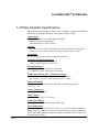
1.2 Probe Amplifier Specifications
The following specifications are listed for the “Standard” configuration (MTI P/N:
8000-2562). Contact the factory for specifications of other versions.
Output Signal
0 - 10 Vdc output (+/-5V offset adjustment range).
1,2
Signal proportional to probe gap
Maximum range 0.5 inch (12.5 mm)
1
Linearity
±0.1% over 10% to 120% of full-scale range using a standard 8-ft probe cable.
4
±0.05% over 10% to 100% of full-scale range available as special order .
Repeatability
± 0.01% of the full-scale range at constant temperature.
Frequency Response/Output Noise
-3dB at 500 Hz/0.20 mV rms, 1 mV p-p
-3dB at 1 kHz/0.28 mV rms, 1.4 mV p-p
3
Dynamic Resolution
1 nm RMS @10Hz –3db Frequency Response
7 nm RMS @ 500Hz –3db Frequency Response
Temperature Stability (after a 30-minute warm-up)
60° to 95°F, (15 to 35°C), drift less than ±0.1% of range.
40° to 100°F, (4 to 38°C), drift less than ±0.25% of range.
Long-Term Stability
Less than ±0.1% of range drift for 100 hours at constant temperature,
±2°F (±1.1°C)
Storage Temperature
0 to 150°F (-18 to 66°C)
Probe Voltage
Proportional to gap, 8.5 V rms max
Output Signal Display
No display on the board level, single channel unit
Power Requirements
+15 Volt DC and –15 Volt DC power, with a ±0.5 Volt DC tolerance and a power
supply noise of less than 0.010 Volts p-p for optimal operation. The Accumeasure
9000 single channel amplifier board unit requires a maximum of 0.075 Ampere DC
from each power supply.
DOCUMENT: 10A000492
REV. 1.0
Page 6 of 30
ACCUMEASURE
TM
SYSTEM 9000
Output Voltage Stability
0.002% full-scale output or less, change over the ±1 Volt DC tolerance range
around the nominal power supply voltages of +15 and –15 Volts DC.
Board Size
0.75 inches (19 mm) high (board plus components)
3.8 inches (97 mm) wide (board plus power cable)
7.25 inches (184 mm) deep (board plus connector extensions)
Board Weight
0.28 Pounds (0.125 kilograms)
1
Output voltage sensitivity factor is 10 V divided by the probe range. A 10-mil (0.254
mm) probe is 10V/10 mil (10V/0.254 mm) or 1 volt/mil (1V/25.4 µm).
2
Output voltage sensitivity may be factory adjusted to 1µ inch/mv (0.0254µ m/mv), with
any MTI probe at time of order.
3
With ASP-10-CTA probe {10-mil (0.254 mm) range} @ 500-Hz frequency response,
with 8-ft cable.
4
Probe must be matched to amplifier
1.3 Probe Specifications
Temperature Rating
Standard Probes: -200 to 400°F (-143 to 200°C)
Probe Connectors and Cable: -200 to 350°F (-143°to 176°C)
High-temperature probes available to 1300°F, contact the factory.
Accuracy
±0.015% of range when calibrated to a known standard
Probe Cable Interchangeability
Accurate within ±0.5% of range without recalibration
Pressure Rating
Standard, 200 psig. Higher pressure probes available for special order
Cable Length
8 feet, provided with probe
Construction
304 stainless steel standard.
INVAR and INCONEL probes available -- contact the factory.
DOCUMENT: 10A000492
REV. 1.0
Page 7 of 30
ACCUMEASURE
TM
SYSTEM 9000
1.4 Receiving Inspection Procedure
The Accumeasure System 9000 single channel board unit is shipped from MTI
fully assembled and packed in a cardboard carton with foam inserts to guard
against shipping damage. Upon receipt, perform the following procedure before
using the unit to perform dimensional measurements:
1. Inspect the exterior of the shipping carton. Note any obvious damage. If
shipping damage is evident, file a claim with the carrier.
2. Remove the amplifier board from the shipping carton. Inspect the board for
any signs of damage.
3. Apply ±15 Volt DC power to the board in accordance the wiring information
provided in the Power Requirements section on page 8).
4. With no probe cable attached to the probe BNC connector, the voltage on the
Output Signal Cable BNC connector should be close to +12 Volts DC.
5. If any problems were found with the Output Signal Cable voltage, contact
MTI at 1-518-218-2550.
DOCUMENT: 10A000492
REV. 1.0
Page 8 of 30
ACCUMEASURE
TM
SYSTEM 9000
1.5 Return Shipment Procedure
Contact MTI Instruments, Inc. at 1-518-218-2550 to receive return authorization
prior to shipping the instrument. Reference the instrument's name, model and serial
numbers on all correspondence. Be sure to include a brief description of the reason
for the return. Place the instrument in the original shipping carton (if available)
and forward prepaid to:
MTI Instruments, Inc.
Supervisor of Manufacturing
325 Washington Avenue Extension
Albany, NY 12205-5505
Mark "RMA" and the RMA number (if a number is issued) on the outside of the
box. If the original packing materials are not available:
1. Wrap the instrument in plastic or heavy paper.
2. Place packing material around all sides of the instrument and pack it in a
cardboard carton.
3. Place instrument and inner container in a sturdy cardboard carton or wooden
box.
DOCUMENT: 10A000492
REV. 1.0
Page 9 of 30
ACCUMEASURE
TM
SYSTEM 9000
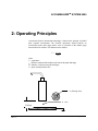
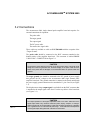
2: Operating Principles
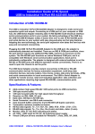
Accumeasure System measurement technology is based on the principle of parallel
plate capacitor measurement. The electrical capacitance formed between an
Accumeasure probe and a target surface varies as a function of the distance (gap)
between these two surfaces. This function can be stated as:
C = (ε) (A)
(D)
where:
C = capacitance.
ε = dielectric constant of the medium (Air) between the probe and target.
D = distance (Gap) between probe and target.
A = probe sensing electrode area.
A (Sensing Area)
ε (Air)
D (Gap)
DOCUMENT: 10A000492
REV. 1.0
Page 10 of 30
ACCUMEASURE
TM
SYSTEM 9000
The Accumeasure System measures the electrical impedance of the capacitance
between a sensing electrode in the probe and a ground-referenced target. The
magnitude of the impedance is proportional to the reciprocal of the capacitance value
as defined by the equation below:
Zc =
1
(ωC)
where:
ω is proportional to the frequency at which the capacitance measurement is performed.
Substituting the equation for capacitance into the impedance equation shows that the
impedance is directly proportional to the gap value D, as shown in the following
equation:
Zc =
(D)
(ω) (ε) (A)
The Accumeasure probe amplifier produces a DC voltage that is linearly proportional
to the average value of the probe gap impedance, and an AC voltage variation from the
DC voltage that is directly proportional to the amplitude of the target vibration. The
amplifier electronic circuitry eliminates the effects of both the probe cable capacitance
and the stray capacitance at the edge of the probe sensing area that could cause nonlinearity of the gap and vibration measurements.
Probe coaxial cable lengths from one to fifty feet (0.3 to 15.2 meters) can be used
with the Accumeasure probe amplifier, and probe with full scale gap values from
5 ten-thousandths of an inch to one half an inch (12.7 micron to 12.7mm) are
available. A summing amplifier is present in the dual-channel model (System 9000-2) to
produce the sum or difference of two gap proportional voltages. This function is ideal for
target thickness measurements (see Thickness Measurements, page 18).
DOCUMENT: 10A000492
REV. 1.0
Page 11 of 30
ACCUMEASURE
TM
SYSTEM 9000
3: Installation Instructions
3.1 Power Requirements
The Accumeasure System 9000 single channel board unit requires a maximum of
0.075 Amperes DC from a +15 Volt DC and a –15 Volt DC power supply. A power
connector is provided on the edge of the circuit board, and power cable with an unterminated, labeled end is shipped with each board. Caution should be exercised when
applying power to this board since there is no fuse protection, or reverse voltage
protection provisions on the board. It is recommended that the power supply lines to
this unit be current limit protected with 0.10 Ampere fuses, or be driven from a power
supply with 0.1 Ampere maximum current capability. It is also recommended that the
power supply voltages be tested for the correct voltage values and polarities on the
power cable plug provided with the board before the plug is connected to the board for
the first time in an installation. There is no power On/Off switch provided with the
single channel board unit, so the probe amplifier will be operational whenever there is
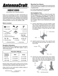
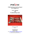
DC voltage on the power supply cable. Refer to Figure 3-1 for the location of the J1
power supply connector on the circuit board, and the location of J1, pin1. The power
supply connections to the J1 connector pins are:
-
Pin 1, +15 Volts DC
-
Pin 2, Power Common (Ground)
-
Pin 3, -15 Volts DC
-
Pin 4, Analog Common (Ground )
Note: Power Common and Analog Common are connected together on the
Accumeasure 9000 single channel board unit. However, separate wires
should be connected from these pins to the ±15 Volt power supply
common.
CAUTION
The DC power supply voltage lines are not fused, and the power supply lines are not reverse
voltage protected on the circuit board of the Accumeasure 9000 single channel board unit.
Ensure the power supply connections and the supply voltages are correct before applying
power to the board.
DOCUMENT: 10A000492
REV. 1.0
Page 12 of 30
ACCUMEASURE
TM
SYSTEM 9000
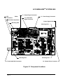
J3 – Output Signal Connector
R51
Adjustment
Offset
J1 – Power Supply Connector
R42 Gain Adjustment
J4 – Summation
Signal Connector
Output Signal Cable
Mounting Hole
Mounting Hole
10
Mounting Hole
Probe Cable BNC Connector
1
Mounting Hole
J2 – Master/ Slave Connector
Figure 3-1 Component locations
DOCUMENT: 10A000492
REV. 1.0
Page 13 of 30
ACCUMEASURE
TM
SYSTEM 9000
3.2 Connections
The Accumeasure 9000, single channel probe amplifier board unit requires five
external connections for operation:
The probe cable.
The target ground.
The output signal
The DC power cable.
The master/slave signal cable.
These cables are available as cable set P/N:7500-6080 with the exception of the
“Target Ground”
The probe cable should be connected to the BNC connector attached to the
bottom surface of the amplifier board unit. This connector is labeled PROBE
CABLE BNC CONNECTOR on Figure 3-1.
CAUTION
The shell of the probe cable input connector on the front panel is driven at the probe carrier
voltage and cannot be grounded. Also, the shield integrity of the probe cable cannot be
broken. If the probe cable is damaged, it is recommended that it be replaced rather than
repaired.
The target ground wire should be connected to the DC ground of power supply
that provides the DC voltages to the Accumeasure 9000 single channel probe
amplifier board unit. This ground connection is returned to the board unit through
the power supply ground connection wires attached to J1, pins 2 and 4 (see Figure
3-1).
The displacement voltage output signal is available from the BNC connector that
is attached to the output signal cable from J3 on the top surface of the board unit
(see Figures 3-1).
CAUTION
DOCUMENT: 10A000492
REV. 1.0
The output impedance of the Signal Output BNC cable is 50 Ohms. Attachment of the
Signal Output cable to any electronic instrument (meter, display, computer, or analog-todigital converter) with an input impedance of less than 50k Ohms will results in a calibration
Pageimpedance
14 of 30
error of greater than 0.1% of the full scale probe range. A total instrument load
on the Signal Output cable greater than 100k Ohm recommended.
ACCUMEASURE
TM
SYSTEM 9000
The output impedance of the amplifier that drives the output signal cable is 50
ohms. This impedance is included in the output signal circuit to ensure signal
stability. The cable that is provided with the board unit is designed to be
compatible with the miniature output connector, J3. This cable should be used for
the best performance of the unit. Additional cable lengths can be added to the
BNC connector at the end of this cable. Any good quality coaxial cable, up to a
length of 100 feet (30 meters) can be used to connect to other equipment.
DC power is provided to the Accumeasure 9000 board unit through the power
cable that is provided with the board. This power supply cable should be
connected to the J1 receptacle on the edge of the board. See Figure 3-1 for the
location of J1.
The master/slave signal cable provides the capability of synchronizing the sine
wave carrier signal frequencies of multiple probe amplifier board units to
minimize the output noise of the units. A square wave sync signal is transmitted
from the master board unit to the slave board units to set the slave board unit
carrier frequency to be in frequency and phase synchronization with the master.
Jumpers are used to set each board to be either a master or a slave. For single
channel units, no cable connection is required and the board set to a master
condition. A “pigtail” harness is provided in cable set P/N: 7500-6080 so that the
board can be synchronized with other boards. Contact MTI for additional jumper,
and master/slave signal cable wiring information if more than one probe amplifier
board unit is used in an installation.
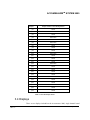
3.3 Control Switches and Jumpers
There are no control switches on the Accumeasure 9000, single channel board
unit. Jumpers are used on the board to set up the optional configurations of the
board circuitry. The jumpers also used during the board calibration process.
Jumpers should not removed from the board or moved to short two adjacent pins
together without specific knowledge of the voltages and signals on the jumper pins.
Random positioning of jumpers on the Accumeasure 9000 board could change the
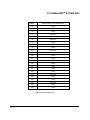
calibration of the unit, or could damage the board circuitry. Table 3-1 indicates
the jumper states (OPEN or SHORTED) for normal operation of the single
channel board unit.
DOCUMENT: 10A000492
REV. 1.0
Page 15 of 30
ACCUMEASURE
Jumper
TM
SYSTEM 9000
Jumper State For Normal Operation
JP1
OPEN
JP2
OPEN
JP3
OPEN
JP4
SHORTED
JP5
SHORTED
JP6
SHORTED
JP7
OPEN
JP8
OPEN
JP9
OPEN
JP10
SHORTED
JP11
OPEN
JP12
OPEN
JP13
OPEN
JP14
SHORTED
JP15
OPEN
JP16
OPEN
JP17
OPEN
JP18
OPEN
JP19
SHORTED
JP20
OPEN
JP21
OPEN
JP22
SHORTED
JP23
OPEN
JP24
OPEN
Table 3-1 Normal Jumper States
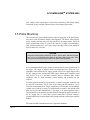
3.4 Displays
There are no displays included on the Accumeasure 9000, single channel board
DOCUMENT: 10A000492
REV. 1.0
Page 16 of 30
ACCUMEASURE
TM
SYSTEM 9000
unit. Display of the output signal is achieved by connecting a DC voltage display
instrument, such as a digital voltmeter to the coaxial output signal cable.
3.5 Probe Mounting
The Accumeasure System 9000 measures probe-to-target gap, so the probe fixture
must have good mechanical stability and alignment. The fixture must hold the
probe securely and keep the probe face parallel to the target surface. Probe tilt
causes measurement errors, so a tilt of less than 5% of range is recommended.
That would mean that for a .020” range sensor, the edge of the sensor should tilt
no more than .001” on a side.
CAUTION
The probe connector and the probe body on ASP-1, ASP-2, ASP-5, and ASP-10 probes
carry a 3 to 5 V rms electrical guard voltage for the cable shield and the probe. These
must not be shorted to ground by the fixture or the system will be inoperative.
It is recommended that the probe fixture be connected to the same ground return as
the target. The target or structure under test should provide a noise-free, lowimpedance return path to the DC supply ground of the power supply that provides
the DC voltages to the Accumeasure 9000 single channel probe amplifier board
unit. Values of up to 1 kilo-ohm resistance may be tolerated under certain
conditions, such as when maximum system linearity and resolution are not
required.
If a direct ground connection is not possible, a capacitive-coupled connection can
be used. Be aware that a 350 pF value in the return path will introduce a 0.1%
full-scale measurement error. Larger capacitances will introduce correspondingly
smaller errors (1000 pF or larger is recommended). In practice, the ground return
path may be provided automatically if the target is at ground potential and is
connected back to the amplifier ground connector through the ground terminal on
the AC supply line. To verify that a proper return path is present, connect a
ground lead directly from the target to the ground connector on the probe amplifier
module.
The probe should be mounted to meet two important conditions:
DOCUMENT: 10A000492
REV. 1.0
Page 17 of 30
ACCUMEASURE
TM
SYSTEM 9000
1. At a minimum excursion, the probe-to-target gap should be no less than 5% of
the probe range.
2. At maximum excursion, the target gap must not exceed 120% of the full-scale
probe range.
Before performing a measurement, ensure that the probe and target under test are
clean and free from debris.
3.6 Probe Cables
MTI capacitance probes are equipped with special, low-noise coaxial cables.
Standard coaxial cables are not acceptable for connecting the probes to probe
amplifier. Cables are available in either 50-ohm or 95-ohm sizes. Specifications:
Diameter
Operating Temperature
50-Ω Cable
0.064 inch (1.626 mm)
-100 to +200ºC
95-Ω Cable
0.144 inch (3.658 mm)
-100 to +200ºC
Most probes are shipped with 95-Ω cables. If cable size is important, please
contact the factory.
Cables may be spliced only if the junction is 100% shielded. Routing the cable
through relays and other switching devices will interfere with the measurement
system. Cylindrical feed-through assemblies may be used, however, when
transitioning through a panel. They must be fully shielded and insulated from the
panel since the shield is not at ground potential. Contact the factory for
information on MTI-manufactured feed-through assemblies.
3.7 Target Grounding
The target should be returned to the DC supply ground of the power supply that
provides the DC voltages to the Accumeasure 9000 single channel probe amplifier
board unit, using a wire or a clip lead. Often a direct probe-to-target ground
connection is not possible, due to target configuration or other mechanical
constraints.
CAUTION
DOCUMENT: 10A000492
REV. 1.0
Poor ground return and connecting the rear panel output connectors to equipment
such as oscilloscopes, chart recorders, or data loggers, can create ground loops,
which will cause errors in excess of 60 Hz in the output and carrier signals.
Page 18 of 30
ACCUMEASURE
TM
SYSTEM 9000
In general, it is recommended that grounding practices for sensitive equipment be
applied when using the Accumeasure amplifier. For additional information on
grounding practices refer to H.W. Ott’s Noise Reduction Techniques in
Electronic Systems (John Wiley and Sons, 1976) or to Chapter 24 of the Analog
Devices Applications Reference Manual (1993).
DOCUMENT: 10A000492
REV. 1.0
Page 19 of 30
ACCUMEASURE
TM
SYSTEM 9000
4: Operating Instructions
4.1 Probe Amplifier Calibration Check
Do not attempt to make adjustments, other than the probe amplifier gain (R42)
and offset (R51) controls that are located on the edge of the board. The board unit
has been calibrated at the factory to perform within published specifications. If
this performance is not attained in the field, check for damaged cables, poor
grounding, fixturing problems, or a damaged probe before attempting an
adjustment of the calibration. Proper operation of the amplifier can be verified by
using a MTI AS-1070-AC probe simulator. If the problem cannot be located,
contact the factory for further instructions.
However, it may be necessary to check and adjust the amplifier calibration for
applications which require maximum accuracy or when the probe and amplifier
have been ordered separately. The best results are obtained when a calibrated
micrometer is used as the probe-positioning device. If this is not available, a standalone micrometer such as the MTI KD-CH-IIIA calibration stand may be used.
The gain and offset controls on the Accumeasure front panel can be used to
calibrate the probe. A slight tilt of the probe in a fixture also may introduce a gain
or offset error that may be eliminated through calibration.
CAUTION
Only potentiometers R42 and R51 on the edge of the board should be adjusted.
Under no circumstances should the settings of any of the other potentiometers on the
board be changed. The other potentiometer settings control amplifier parameters and
should only be adjusted at the MTI factory.
DOCUMENT: 10A000492
REV. 1.0
Page 20 of 30
ACCUMEASURE
TM
SYSTEM 9000
RECOMMENDED EQUIPMENT
1.
A Voltmeter with a minimum resolution of .0001V dc and accuracy of
±0.001V dc.
2. A Micrometer with a minimum resolution of 0.05% of the probe range (if
available) and accuracy of ±0.1% of the probe range. (An MTI KD-CH-IIIA
Calibration Fixture may be used for this purpose; refer to the KD-CH-IIIA
Operating Instruction Manual to compare the fixture resolution to the
calibration requirements.)
BASIC CALIBRATION
Perform calibration by adjusting the R42 GAIN and the R51 OFFSET controls.
Offset is adjusted while the probe is at 10% of range. Gain is adjusted at 100% of
range. Use the following procedure:
1. Set the voltmeter to monitor the output signal voltage from the amplifier board
unit.
2. With the power supply to the board unit turned off, adjust the probe so it is
lightly touching the target.
3. Zero the micrometer and then move it back to 10% of the intended range. Turn
the power supply for the board unit on.
4. Adjust the R51, OFFSET potentiometer until the output voltage reads 1.000
Vdc.
5. Move the micrometer to 100% of range, and adjust the R42, GAIN
potentiometer until the output voltage reads 10.000 Vdc.
6. Readjust the micrometer to 10% of range and recheck the 10% point
(1.000 V). Readjust R51 if necessary, and recheck the 100% limit.
7. Repeat steps 5 and 6 until the voltage at 10% of range is 1.000 ±0.001 Vdc
and the voltage at 100% of range is 10.000 ±0.001 Vdc.
8. Verify several points between the minimum and maximum limits.
If this procedure does not produce the desired system accuracy, more elaborate
calibrations such as linearizing the output may be accomplished by readjusting the
potentiometers on top surface of the board unit. These adjustments must be made
at the MTI factory or by a qualified MTI representative.
DOCUMENT: 10A000492
REV. 1.0
Page 21 of 30
ACCUMEASURE
TM
SYSTEM 9000
4.2 “Pushed” Amplifiers and Probes
Some applications require probes with smaller diameters to achieve the sensing
ranges of larger-diameter probes. For example, a 20-mil (0.508-mm) range would
normally require an ASP-20-CTA probe with a diameter of 0.437 inch (11.099
mm) for use with a standard amplifier. If a smaller probe diameter is required, the
amplifier may be “pushed” by a factor of 2. This would allow smaller sized
probes, such as an ASP-10-CTA, with a diameter of 0.250 inch (6.25 mm) to be
operated over a 20-mil (0.508-mm) range.
Similar effects can be achieved with other combinations of probe range and
amplifier push. The maximum push recommended is 40X.
When employing “pushed” amplifier and probe combinations, the output versus
distance must be individually calibrated in order to obtain maximum accuracy and
linearity. The level of output noise generated by the “pushed” amplifier also
increases in amount equal to the push factor.
For example, a standard probe amplifier with an ASP-10 probe and an 8-foot (2.4
meter) cable has an output noise level of 1.0 ±0.2 millivolt peak-to-peak at a 10
mil (254 microns) probe-to-target air gap. A 5X pushed amplifier working with
the same probe and cable will have a 5.0 ±1.0 millivolts peak-to-peak output noise
at the same gap. The linearity of pushed probe amplifiers also may be degraded by
±0.15% for push values between 10X and 40X using long probe cables.
It is recommended that you contact an MTI representative or factory applications
personnel for more information on pushed probe and amplifier combinations.
4.3 Conductive Target Thickness Measurements
Two Accumeasure System 9000 single channel board units can be used to perform
thickness measurements. A probe amplifier signal summation circuit located on
the 9000 board unit can be set to produce a [Channel 1 + Channel 2] summation
for the correct addition of two probe signals (contact MTI if there is a question
about the exact configuration of the summation circuit). One of the terminals on
the P1 power supply voltage connector provides a path for connecting the output
signal from a second Accumeasure 9000 single channel board unit. This path
allows the signal to be added directly to the output signal of the first amplifier to
preform the thickness measurement summation. A summation output signal
connector, J4, is also available to provide the thickness signal to an external
DOCUMENT: 10A000492
REV. 1.0
Page 22 of 30
ACCUMEASURE
TM
SYSTEM 9000
display or data acquisition instrumentation. A special summation signal output
cable that attaches to the J4 connector is provided with probe amplifier board units
that are to be used to perform thickness measurements.
To perform the thickness measurement, the Accumeasure 9000 single channel
boards are provided with a wide voltage range offset adjustment that allows the
summation signal value to be set to zero volts at a nominal target thickness value
(refer to the measurement procedure below). With the 9000 board unit set up to
perform the thickness measurement, the J4 Summation Signal Output connector
produces an output that has an increasingly positive magnitude as the target
thickness decreases.
MEASUREMENT PROCEDURE
1. Fixture the probes on opposite sides of the target with the center-line of the
two probe sensing faces directly in line with each other. Remove the target and
set the air gap between the probe sensing faces so it is equal to the mean
thickness of the target plus the sensing range of probes. For example, if the
target thickness is 0.250 inch (6.35 mm) and probes with a range of 0.050
inch (1.27 mm) are being used, the total gap between the probe faces would
be set at approximately 0.300 inch (7.62 mm). Make sure the probe-to-target
air gap for Probe 1 and Probe 2 does not exceed the measuring range of the
probes.
2. Connect the probes to two Accumeasure System 9000 single channel board
units.
3. Place a target with known thickness midway between the probes. This test
target should be the same thickness as the object that will be gauged.
4. Ground the target.
5. Connect a digital voltmeter (DVM) or oscilloscope (whichever is used) to the
Channel 1 board output signal cable.
6. Adjust the probe gap until the output voltage is between 0 and +10V (+5 to +7
volts is ideal). Keep in mind the maximum excursion of targets to be gauged.
The output voltage (gap) should not exceed the linear range of the probe.
7. Vary the wide range offset control, R56 to produce an output of zero volts.
8. Connect the DVM or oscilloscope to the Channel 2 board output signal cable
and repeat steps 6 and 7 for Channel 2 output signal, varying R56 on the
Channel 2 board to produce an output voltage of zero volts.
9. Connect the DVM or oscilloscope to the summation signal output cable from
the Channel 1 board unit. The voltage display should read zero volts,
DOCUMENT: 10A000492
REV. 1.0
Page 23 of 30
ACCUMEASURE
TM
SYSTEM 9000
corresponding to the test target thickness. Thicker targets will read as positive
numbers on the meter display. Thinner targets will read as negative
displacement values.
NOTE: The Channel 2 board unit J1, pin 10 output signal has to be connected to
the J1, pin 10 of the Channel 1 board unit and the jumpers on both boards installed
per MTI instructions for the signal summation to function. Contact MTI for the
specific jumper settings for thickness measurement.
10. To determine thickness, multiply the voltage change by the probe sensitivity
factor. For example, 50-mil (1.27-mm) range probes have a sensitivity factor
of 5 micro-inches (0.127 µm) per millivolt. If the output signal increases by
+20 millivolts, then the target is increasing in thickness by 100 microinches
(2.54 µm).
NOTES OF CAUTION FOR THICKNESS MEASUREMENTS
4.4.
•
Keep low-noise coaxial cables away from each other to prevent crosstalk. A
very large guard signal in close proximity to a very low signal can easily
cause a 1% thickness error.
•
The probe fixture must be extremely rigid.
•
If one or both probes are mounted in recessed wells, the probes may need to be
re-calibrated, as the linearity may change when the probes are recessed. It is
also recommended that the well diameter be 50% greater than the probe outer
diameter to ensure linear operation at large gaps.
•
Avoid target tilt errors. Range-extended probes (“pushed probes”) are less
susceptible to target tilt error. However, noise increases with push. Target tilt
warps the capacitance field, starting at the point of the target’s closest
approach. Using smaller probe sensing areas with large air gaps will minimize
the tilt effect.
•
For thickness measurement of non-conductive, dielectric materials contact
MTI to obtain application notes that describe the use of the Accumeasure
System with this type of target.
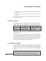
MASTER/SLAVE OPERATION
When operating multiple probes close to each other, it is necessary to synchronize the carrier
signals of the respective amplfiers. This will eliminate “beat-frequency” effects between
DOCUMENT: 10A000492
REV. 1.0
Page 24 of 30
ACCUMEASURE
TM
SYSTEM 9000
adjacent probe/amplifier pairs. Normally the amplfiers are configured as “Masters” with
nothing connected to J2. See the table below for the relevant signals:
Connector: J2
Harness 7500-6080 wire color
Pin-1
Pin-2
Pin-3
SYNC OUT
INPUT (SYNC IN)
MASTER/*SLAVE SELECT
OPEN = MASTER
GND=SLAVE
RED
GRN
WHT
Pin-4
Pin-5
Pin-6
GND
N/C
N/C
BLK
Cut the WHITE and BLACK wires short (2”) and connect them together to configure an
amplifier as a “SLAVE”. Connect RED from the connector on the MASTER to the GREEN
wire on the SLAVE unit.
Unused signals:
MASTER:
“SYNC IN”, GRN
“*SLAVE”, WHT
“GND”, BLK
SLAVE:
“SYNC OUT”, RED
DOCUMENT: 10A000492
REV. 1.0
Page 25 of 30
ACCUMEASURE
TM
SYSTEM 9000
5: Troubleshooting
CAUTION
Observe all electrical safety precautions when performing maintenance.
Accumeasure System 9000 single channel board units require specialized servicing
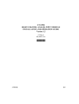
techniques and should not be serviced in the field. The troubleshooting table in this
section should help you determine if the problem exists in the Accumeasure
equipment or in your auxiliary equipment. If the trouble is on the Accumeasure
System 9000 board, it should be returned to the factory for servicing.
Before following the troubleshooting procedure:
1. Set up a probe and grounded target so that probe-to-target gap is within the
probe full scale range,
2. Connect the probe to the Accumeasure 9000 Probe Amplifier board with an
MTI probe cable,
3. Apply DC power within the specified operating range to the Probe Amplifier
(refer to the Power Requirements section, pg. 8),
4. Refer to the table on the following page to determine the course of action that
should be taken to solve a problem with the application of the Accumeasure
System 9000 board unit.
DOCUMENT: 10A000492
REV. 1.0
Page 26 of 30
ACCUMEASURE
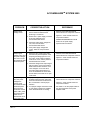
PROBLEM
Output signal
voltage is zero.
CORRECTIVE ACTION
1. Ensure that the DC power supply for
the Accumeasure 9000 board is
producing ±15 Volts DC.
2. Ensure the P1 power supply connector
is securely attached to the
Accumeasure 9000 board.
3. Check the power supply voltages on
TP1, TP2, and TP3 of the
Accumeasure 9000 board.
TM
SYSTEM 9000
REFERENCE
1. INSTALLATION INSTRUCTIONS
manual section for component locations
2. Figure 5-1 of this manual section for
component locations.
3. POWER REQUIREMENTS manual
section for the power supply
requirements of the board.
4. If the power supply voltages are
correct, follow the next procedure
below.
Output signal
voltage is zero and
the power voltages
are correct on the
Accumeasure 9000
board test points.
1. Disconnect the coaxial probe cable
from the front panel receptacle. If the
output signal voltage goes to a nonzero value, check cable for shield to
center short circuit, and the probe for
interelectrode short circuits.
1. INSTALLATION INSTRUCTIONS
manual section for component locations
2. Figure 5-1 of this manual section for
component locations.
2. Check the voltage at the output signal
test point TP13 on the Accumeasure
9000 board with DC voltmeter. If the
TP13 voltage is a non-zero value,
check the output signal cable for a
short circuit between the center lead
and the shield, and check for an open
center lead.
Output voltage is
zero; the power
voltages are
correct on the
Accumeasure 9000
board test points
for the channel
under test; and the
probe cable, probe,
and output signal
cable are not
shorted and do not
have open leads .
DOCUMENT: 10A000492
REV. 1.0
1. If jumper changes on the probe
amplifier board have been performed
since the unit has been received from
MTI, contact MTI to review jumper
selection.
1. INSTALLATION INSTRUCTIONS
manual section for component locations.
2. If no jumper changes have been made
or if the proper jumpers are installed,
return the board to MTI for testing.
3. See Table 5-1 for the jumper states for
the normal operation of the probe
amplifier board.
2. Figure 5-1 of this manual section for
component locations.
Page 27 of 30
ACCUMEASURE
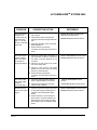
PROBLEM
CORRECTIVE ACTION
The output signal
voltage is not
+10.00 Vdc at the
full-scale probe
gap or +1.00 Vdc
at 10% of full-scale
probe gap.
1. Check that the range of the probe under
test is correct.
2. Verify that the probe and target are
touching when the probe gap should be
zero.
TM
SYSTEM 9000
REFERENCE
1. PROBE AMPLIFIER CALIBRATION
CHECK for gain adjustment.
2. PROBE MOUNTING manual section.
3. Check the calibration of the front panel
GAIN adjustment.
4. Ensure that the ground return
connection from the target to the unit is
intact.
The output signal
voltage is higher
than +12 Volt DC
at all probe-totarget gap settings.
1. Check the probe cable connection to
the probe BNC connector; ensure that
the cable is securely attached to the
connector.
1. TARGET GROUNDING manual section.
2. PROBE MOUNTING manual section.
2. Check for an open circuit in the center
wire of the probe cable.
3. Check for open circuit in the probe
between the connector and the sensing
element on the probe face.
4. Ensure that the ground return
connection from the target to the unit is
intact.
The noise on the
rear-panel output
voltage is
abnormally high.
1. Check the probe and probe cable for
loose or high resistance connections.
1.
TARGET GROUNDING manual
section.
2. Check along the length of the probe
cable for cuts or defects.
2.
PROBE MOUNTING manual section.
Excessive 60-Hz
noise on the output
signal.
1. Check for a good AC power line ground
on the power supply providing the DC
voltages to the Accumeasure 9000
board.
1. TARGET GROUNDING manual section.
2. PROBE MOUNTING manual section
2. Ensure that there is a low resistance
ground return connection between the
target and the power supply providing
DC voltages to the Accumeasure 9000
board.
DOCUMENT: 10A000492
REV. 1.0
Page 28 of 30
TM
SYSTEM 9000
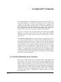
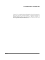
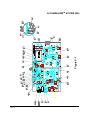
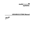
Figure 5-1
ACCUMEASURE
DOCUMENT: 10A000492
REV. 1.0
Page 29 of 30
ACCUMEASURE
Jumper
TM
SYSTEM 9000
Jumper State For Normal Operation
JP1
OPEN
JP2
OPEN
JP3
OPEN
JP4
SHORTED
JP5
SHORTED
JP6
SHORTED
JP7
OPEN
JP8
OPEN
JP9
OPEN
JP10
SHORTED
JP11
OPEN
JP12
OPEN
JP13
OPEN
JP14
SHORTED
JP15
OPEN
JP16
OPEN
JP17
OPEN
JP18
OPEN
JP19
SHORTED
JP20
OPEN
JP21
OPEN
JP22
SHORTED
JP23
OPEN
JP24
OPEN
Table 5-1 Normal Jumper States
DOCUMENT: 10A000492
REV. 1.0
Page 30 of 30