1
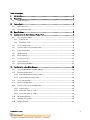
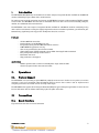
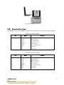
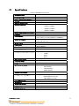
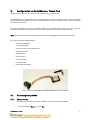
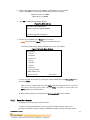
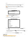
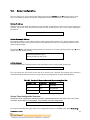
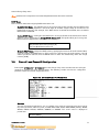
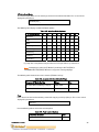
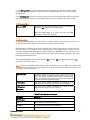
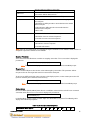
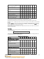
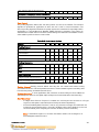
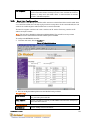
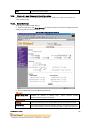
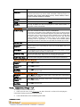
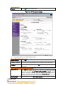
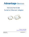
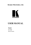
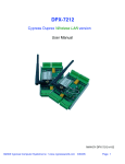
WFS802b WiFi 802.11 Serial Module with Antenna
Module User Manual
Version: 1.0.4
June 2005
Table of Contents
I.
Introduction..................................................................................................................................... 2
II.
Operations....................................................................................................................................... 2
II.1.
III.
Protocol Support ....................................................................................................................................2
Connections .................................................................................................................................... 2
III.1.
Board Structure ......................................................................................................................................2
III.2.
Connector Description........................................................................................................................... 3
IV.
Specifications ................................................................................................................................. 4
V.
Configuration via Serial Mode or Telnet Port ............................................................................ 5
V.1.
Accessing Setup Mode........................................................................................................................... 5
V.1.1.
Telnet Access ..................................................................................................................................... 5
V.1.2.
Serial Port Access .............................................................................................................................6
V.2.
Server Configuration ..............................................................................................................................8
V.3.
Channel 1 and Channel 2 Configuration..............................................................................................9
V.4.
Email Configuration..............................................................................................................................20
V.5.
WLAN Settings.....................................................................................................................................20
V.6.
Expert Settings...................................................................................................................................... 21
V.7.
Security Settings.................................................................................................................................. 22
V.8.
Factory Defaults................................................................................................................................... 23
V.9.
Exit Configuration Mode..................................................................................................................... 25
VI.
Configuration using Web-Manager .......................................................................................... 26
VI.1.
Accessing WFS802b using Web-Manager .................................................................................... 26
VI.2.
Network Configuration........................................................................................................................ 27
VI.2.1. Automatic IP Address Configuration ......................................................................................... 27
VI.2.2. Static IP Address Configuration.................................................................................................. 28
VI.3.
Server Configuration ........................................................................................................................... 28
VI.4.
Host List Configuration....................................................................................................................... 29
VI.5.
Channel 1 and Channel 2 Configuration........................................................................................... 30
VI.5.1. Serial Settings ................................................................................................................................. 30
VI.5.2. Connection Settings - TCP............................................................................................................ 31
VI.5.3. Connection Settings - UDP ...........................................................................................................33
VI.6.
WLAN Configuration ........................................................................................................................... 34
VI.7.
OEM Pin Configuration ....................................................................................................................... 36
VI.8.
Updating Settings .................................................................................................................................37
Copyright © Dr Robot Inc. 2005
1
I.
Introduction
The WFS802b WiFi (802.11b) serial module is the most compact, integrated solution available to add 802.11b
wireless networking to your robots with a serial interface.
To enable access to a local network or the internet, the WFS802b integrates a fully developed TCP/IP network
stack and OS. The WFS802b also includes an embedded web server that can be used to remotely configure,
monitor, or troubleshoot the attached device.
The WFS802b is the most compact, integrated solution available to add 802.11b wireless networking to any
device with a serial interface. Using our highly integrated hardware and software platform, you will add to your
bottom line by significantly reducing product development time, risk, and cost.
Features
.
.
.
.
.
.
.
.
.
Serial to 802.11b conversion
Dual serial ports up to 921.6kbps per port
Integrated industry standard 802.11b wireless interface
128bit WEP Encryption for security
Connect any serial device to a wireless network
Stable, field proven TCP/IP protocol suite and Web-based application framework
Easy configuration through a web interface
Embedded web server
High performance throughput
Applications
. Robotic systems: both run-time and development-stage communication
. General-purpose wireless data communication
II.
Operations
II.1.
Protocol Support
The WFS802b uses the widely accepted 802.11b protocol to connect to a wireless access point or an ad hoc
network. It uses the Transmission Control Protocol (TCP) to ensure that no data is lost or duplicated and
everything sent to the connection arrives correctly at the target.
The WFS802b also supports User Datagram Protocol (UDP) for typical datagram applications in which devices
interact with other devices without maintaining a point-to-point connection.
III.
Connections
III.1.
Board Structure
Figure III.1 illustrates the structure of the board
Copyright © Dr Robot Inc. 2005
2
Figure III.1 WFS802b Structure
III.2.
Connector Description
The WFS802b is connected to WiRobot system via an 8-pin 2.54 mm-pitch single row connector1 (COM1):
Table III.1 Connector1 (COM1)
Pin
1
2
3
4
5
6
7
8
Name
VCC
RXD
TXD
RTS
CRTS
GND
NC
NC
Function
+3.3 V
Data receiving
Data transmitting
Request to send
Clear to send
Power supply ground
Reserved
Reserved
Table III.2 Connector2 (COM2)
Pin
1
2
3
4
5
6
7
8
Copyright © Dr Robot Inc. 2005
Name
NC
RXD
TXD
RTS
CRTS
GND
NC
NC
Function
Reserved
Data receiving
Data transmitting
Request to send
Clear to send
Power supply ground
Reserved
Reserved
3
IV.
Specifications
Table IV.1 WFS802b Specification
Network Standard
Frequency Range
Radio # of Selectable Channels
Security
Maximum Receive Level
Receiver Sensitivity
WLAN Power and Link LED Current
Firmware
Serial Interface
Serial Line Formats
Modem Control
Flow Control
Network Interface
Protocols Supported
Data Rates With Automatic Fallback
Media Access Control
Frequency Range
Range
Modulation Techniques
Transmit Output Power
Average Power Consumption
Peak Supply Current
Management
Weight with antenna
Temperature
Size (w/o antenna)
Copyright © Dr Robot Inc. 2005
IEEE 802.11b
2.412 – 2.484 GHz
14 Channels
Password protection, locking features, WEP 64/128
-10dBm (with PER < 8%)
. -82dBm for 11Mbps
. -87dBm for 5.5Mbps
. -89dBm for 2.0Mbps
. -93dBm for 1.0Mbps
Max: 4mA
Upgradeable via serial port
CMOS (Asynchronous) 3.3V-level signals
Rate is software selectable (300 bps to 921600 bps)
7 or 8 data bits, 1-2 Stop bits,
Parity: odd, even, none
DTR, DCD
XON/XOFF (software), CTS/RTS (hardware), none
Wireless 802.11b
802.11b, UDP, TCP, DHCP
. 11Mbps
. 5.5Mbps
. 2Mbps
. 1Mbps
CSMA/CA with ACK
2.412 – 2.484 GHz
Up to 328 feet indoors
. CCK (11Mbps)
. CCK (5.5 Mbps)
. DQPSK (2 Mbps)
. DBPSK (1 Mbps)
14dBm ± 1dBm
. 1280 mW (WLAN mode; maximum data rate)
. 820 mW (WLAN mode; idle)
. 710 mW (Ethernet mode)
460 mA
Internal web server
50 grams
Operating range, WLAN: -40°C to +70°C
50 mm x 40 mm x 15 mm
4
V.
Configuration via Serial Mode or Telnet Port
Configure the unit so that it can communicate on a network with your serial device.
The WFS802b unit is configurable using a terminal program to access the serial port locally. Using this terminal
program to respond to prompts is referred to as the Setup Mode. A Telnet connection may also be used to configure
the unit over the network.
The unit’s configuration is stored in nonvolatile memory and is retained without power. You can change the
configuration at any time. The unit performs a reset after the configuration has been changed and stored.
Note: The menus in this section show a typical device. Not all devices display information in the same manner.
This chapter includes the following topics:
.
Accessing Setup Mode
.
Server Configuration
.
Channel 1 and Channel 2 Configuration
.
Email Configuration
.
WLAN Settings
.
Expert Settings
.
Security Settings
.
Factory Defaults
.
Exit Configuration Mode
Figure V.1 Connection WFS802b with MCR3210P RS232 Interface Module
V.1.
Accessing Setup Mode
V.1.1.
Telnet Access
To configure the unit over the network, establish a Telnet connection to port 9999:
1. From the Windows Start menu, click Run.
Copyright © Dr Robot Inc. 2005
5
2. From the Run dialogue box, type the following command (where x.x.x.x is the IP
address and 9999 is the unit’s fixed network configuration port number):
Windows: telnet x.x.x.x 9999
UNIX: telnet x.x.x.x:9999
3. Click OK. The following information displays:
Figure V.1. MAC Address
MAC address 00204AFFFF30
Software version 05.3(040129)WPT
Press Enter to go into Setup Mode
4. To enter the Setup Mode, press Enter within 5 seconds.
Note: Connection fails if Enter is not pressed within 5 seconds.
The configuration settings display, followed by the setup menu options:
Figure V.2. Setup Menu Options
Change Setup:
0 Server
1 Channel 1
2 Channel 2
3 Email
4 WLAN
5 Expert
6 Security
7 Factory defaults
8 Exit without save
9 Save and exit
Your choice ?
5. Select an option on the menu by entering the number of the option in the Your choice ? field
and pressing Enter.
View the current configuration by pressing Enter from the Change Setup menu. To enter a
value for a parameter, type the value and press Enter. To confirm a current value, press
Enter (without inputted parameters).
6. When finished, save the new configurations (9 Save and exit). The unit reboots.
V.1.2.
Serial Port Access
To configure the unit through a serial connection:
1. Connect a console terminal or PC running a terminal emulation program to your unit's
serial port. The default serial port settings are 9600 baud, 8 bits, no parity, 1 stop bit, no flow
Copyright © Dr Robot Inc. 2005
6
control.
2. Reset the WFS802b unit by cycling the unit's power (turning the power off and back on).
Immediately upon resetting the device, enter three lowercase x characters (xxx).
Note: The easiest way to enter Setup Mode is to hold down the x key at the terminal (or
emulation) while resetting the unit. This must be done within three seconds of resetting the
WFS802b.
3. Upon connection, the following information displays:
Figure V.3. MAC Address
MAC address 00204AFFFF30
Software version 05.3 (040129) WPT
Press Enter to go into Setup Mode
4. To enter the Setup Mode, press Enter within 5 seconds
Note: Connection fails if Enter is not pressed within 5 seconds.
The configuration settings display, followed by the setup menu options:
Figure V.4. Setup Menu Options
Change Setup:
0 Server
1 Channel 1
2 Channel 2
3 Email
4 WLAN
5 Expert
6 Security
7 Factory defaults
8 Exit without save
9 Save and exit
Your choice ?
5. Select an option on the menu by entering the number of the option in the Your choice ? field and
pressing Enter.
View the current configuration by pressing Enter from the Change Setup menu. To enter a value
for a parameter, type the value and press Enter. To confirm a current value, press Enter
(without inputted parameters).
6. When finished, save the new configurations (9 Save and exit). The unit reboots
Copyright © Dr Robot Inc. 2005
7
V.2.
Server Configuration
The unit’s basic server (i.e. network) values display upon selecting Server (option 0 from the Change Setup
menu). The following sections describe the configurable parameters within the Server configuration menu.
Set the IP Address
If DHCP is not used to assign IP addresses, enter it manually. The IP address must be set to a unique value in the
network. Enter each octet and press Enter between each section inputted. The current value is displayed in
parentheses.
IP Address : ( 0) ( 0) ( 0) ( 0)
Set the Gateway IP Address
The gateway address, or router, allows communication to other LAN segments. The gateway address should
be the IP address of the router connected to the same LAN segment as the unit. The gateway address must be
within the local network.
The default is N (No), indicating the gateway address has not been set. To set the gateway address, type Y. At the
prompt, enter the gateway address.
Set Gateway IP Address (N) ? Y
Gateway IP addr ( 0) ( 0) ( 0) ( 0)
Set the Netmask
A netmask defines the number of bits taken from the IP address that are assigned for the host part.
Netmask: Number of Bits for Host Part (0=default) (0)
The unit prompts for the number of host bits to be entered, then calculates the netmask, which displays in
standard decimal-dot notation when the saved parameters are displayed (for example, 255.255.255.0).
Table V.1. Standard IP Network Netmasks Representing Host Bits
Network Class
Host Bits
Netmask
A
24
255.0.0.0
B
16
255.255.0.0
C
8
255.255.255.0
Change Telnet Configuration Password
Setting the Telnet configuration password prevents unauthorized access to the setup menu via a Telnet
connection to port 9999 or via web pages. The password must have 4 characters.
Change telnet config password (N) ?
An enhanced password setting (for Telnet access only) of 16 characters is available under option 6 Security
Copyright © Dr Robot Inc. 2005
8
from the Change Setup menu.
Note: A password is not required to access the Setup Mode window via a serial connection.
DHCP Name
There are three methods for assigning DHCP names to the unit.
. Default DHCP Name: If the DHCP name is not changed and the IP is 0.0.0.0, then the DHCP name
defaults to CXXXXXX (XXXXXX is the last 6 digits of the MAC address shown on the label on the
bottom/side of the unit). For example, if the MAC address is 00-20-4A-12-34-56, then the default
DHCP name is C123456.
.
Custom DHCP Name: Create your own DHCP name. If using an IP address of 0.0.0.0, then the last
option in Server configuration is Change DHCP device name. This option allows you to change the
DHCP name to an alphanumeric name (LTX in the example).
Change DHCP device name (not set) ? (N)
Enter new DHCP device name : LTX
.
V.3.
Numeric DHCP Name: Change the DHCP name by specifying the last octet of the IP address. When
using this method, the DHCP name is LTXYY where YY is the last octet of the IP address. If the IP
address specified is 0.0.0.12, then the DHCP name is LTX12. This method only works with 2 digit
numbers (0-99).
Channel 1 and Channel 2 Configuration
Select option 1 Channel 1 or 2 Channel 2 from the Change Setup menu to define how the serial port
responds to network and serial communications. The following sections describe the configurable
parameters within the Channel configuration menu.
Figure V.5. Serial and Telnet Port Parameters
Baudrate
The unit and attached serial device, such as a modem, must agree on a speed or baud rate to use for
the serial connection. Valid baud rates are 300, 600, 1200, 2400, 4800, 9600 (default), 19200,
38400, 57600, 115200, 230400, 460800, or 921600. The current value is displayed in
parentheses.
Baudrate (9600) ? _
Copyright © Dr Robot Inc. 2005
9
I/F (Interface) Mode
The Interface (I/F) Mode is a bit-coded byte entered in hexadecimal notation. The current value is
displayed in parentheses.
I/F Mode (4C) ? _
The following table displays available I/F Mode options:
Table V.2. Interface Mode Options
I/F Mode Option
RS-232C (1)
7
6
5
4
3
2
7 Bit
1
0
8 Bit
1
1
No Parity
0
0
Even Parity
1
1
Odd Parity
0
1
1 stop bit
0
1
2 stop bits(1)
1
1
1
0
0
0
(1) 2 stop bits are implemented by the software. This might influence performance.
Note: If attempting to select an I/F Mode bit pertaining to RS-422/485, a
“WARNING: RS-422/485 I/F Modes not supported” message displays.
The following table demonstrates some common I/F Mode settings:
Table V.3. Common Interface Mode Settings
Common I/F Mode Setting
Binary
Hex
RS-232C, 8-bit, No Parity, 1 stop bit
0100 1100
4C
RS-232C, 7-bit, Even Parity, 1 stop bit
0111 1000
78
Flow
Flow control sets the local handshaking method for stopping serial input/output. The current value is
displayed in parentheses.
Flow (0) ?
Use the following table to select flow control options:
Table V.4. Flow Control Options
Copyright © Dr Robot Inc. 2005
Flow Control Option
Hex
No flow control
00
10
XON/XOFF flow control
01
Hardware handshake with RTS/CTS lines
02
XON/XOFF pass characters to host
05
Port Number
The Port No setting represents the source port number in TCP connections. It is the number that
identifies the channel for remote initiating connections. The port number functions as the TCP/UDP
source port number for outgoing packets. Packets sent to the unit with this port number are received
to this channel. The port number selected is the Incoming TCP/UDP port and Outgoing TCP/UDP
source port.
Port No (10001) ?
The current value is displayed in parentheses. The default setting for Port 1 is 10001. The range is 165535, except for the following reserved port numbers:
Table V.5. Reserved Port Numbers
Port Numbers
Reserved for
1 – 1024
Reserved
9999
Telnet setup
14000-14009
Reserved for Redirector
30704
Reserved (77F0h)
30718
Reserved (77FEh)
Note: It is recommended to not use the reserved port numbers for this setting
as incorrect operation may result.
Use Port 0 for the outgoing local port to change with each connection. The port range is 50,000 to
59,999. Each subsequent connection increments the number by 1 (it wraps back around to 50,000).
Only use this automatic port increment feature to initiate a connection using TCP. Set the port to a nonzero value when the unit is in a passive mode or when using UDP instead of TCP.
Connect Mode
Connect Mode defines the unit’s connection method and its reaction to incoming connections
over the network. The current value is displayed in parentheses.
ConnectMode (C0) ?
Enter Connect Mode options in hexadecimal notation:
Table V.6. Connect Mode Options
Connect Mode Option
7
6
5
0
0
0
4
3
2
1
0
a) Incoming Connection
Never accept incoming
Copyright © Dr Robot Inc. 2005
11
Accept with modem-control_in Active
0
1
0
Always Accept
1
1
0
b) Response
Nothing (quiet)
0
Character response (C=connect,
D=disconnect, N=unreachable)
1
c) Active Startup
No active startup
0
0
0
0
With any character
0
0
0
1
With modem_control_in Active
0
0
1
0
With a specific start character
0
0
1
1
Manual connection
0
1
0
0
Autostart
0
1
0
1
1
1
0
0
Hostlist
0
0
1
0
d) Datagram Type
Directed UDP
e) Modem Mode
Full Verbose
1
0
1
1
0
Without Echo
0
0
1
1
0
Numeric modem result codes
1
0
1
1
1
a)
Incoming Connection
Never Accept Incoming
Rejects all external connection attempts
Accept with modem_control_in Active
Accepts external connection requests only
when the modem_control_in input is asserted.
Cannot be used with Modem Mode
Always Accept
Accepts any incoming connection when a
connection is not already established. Default
setting
b)
Response
Character Response
A single character is transmitted to the serial port when
there is a change in connection state:
C = connected, D = disconnected, N = host unreachable.
This option is overridden when the Active Start Modem
Mode or Active Start Host List is in effect. Default
setting is Nothing (quiet).
No Active Startup
Does not attempt to initiate a connection. Default setting
With Any Character
Attempts to connect when any character is received from
the serial port
Accept with
modem_control_in Active
Attempts to connect when the modem_control_in input
changes from not asserted to asserted
Copyright © Dr Robot Inc. 2005
12
With a
Character
Specific
Manual Connection
Start Attempts to connect when it receives a specific start
character from the serial port. The default start character
is carriage return
Attempts to connect when directed by a command string
received from the serial port. The first character of the
command string must be a C (ASCII 0x43), and the last
character must be either a carriage return (ASCII 0x0D)
or a line feed (0x0A). No blanks or space characters may
be in the command string. Between the first and last
command string characters must be a full or partial
destination IP address and can include a destination port
number.
The IP address must be in standard dot-decimal notation
and may be a partial address, representing the least
significant 1, 2, or 3 bytes of the remote IP address. The
period is required between each pair of IP address
numbers.
If present, the port number must follow the IP address,
must be presented as a decimal number in the range 165535, and must be preceded by a forward slash (ASCII
0x2F). The slash separates the IP address and the port
number. If you omit the port number from a command
string, the internally stored remote port number starts a
connection.
If a partial IP address is presented in a command string, it
is interpreted to be the least significant bytes of the IP
address and uses the internally stored remote IP address
to provide the most significant bytes of the IP address. If
the IP address entered is 0.0.0.0/0, the device server
enters Monitor Mode.
For example, if the remote IP address already configured
in the unit is 129.1.2.3, then an example command string
would be C3/7. (This would connect to 129.1.2.3 and port
7.) You may also use a different ending for the connection
string. For example, C50.1/23 would connect you to
129.1.50.1 and port 23.
Table V.7. Manual Connection Address Example
Command String
Result if remote IP is 129.1.2.3 and remote port is 1234
C121.2.4.5/1
Complete override; connection is started with host 121.2.4.5, port 1
C5
Connects to 129.1.2.5, port 1234
C28.10/12
Connects to 129.1.28.10, port 12
C0.0.0.0/0
Connects to 129.1.28.10, port 12; enters Monitor Mode
Autostart (Automatic
Connection)
The unit automatically attempts a connection to the
remote IP address and port after booting up
Hostlist
If this option is set to True, the device server scrolls
through the host list until it connects to the first available
device listed in the host list table. Once it connects, the
unit stops further attempts. If this connection fails, the unit
continues to scroll through the table until it is able to
connect to the next available IP address in the host list.
Hostlist supports a minimum of 1 and a maximum of 12
entries. Each entry contains the IP address and the port
Copyright © Dr Robot Inc. 2005
13
number.
The hostlist is disabled for Manual Mode and for Modem
Mode. The unit will not accept a data connection from a
remote device when the hostlist option is enabled.
Figure V.6. Hostlist Example
Baudrate (9600) ?
I/F Mode (4C) ?
Flow (00) ?
Port No (10001) ?
ConnectMode (C0) ?25
Hostlist :
No Entry !
Change Hostlist ? (N) Y
01. IP address : (000) 172.(000) 19.(000) 0.(000) 1 Port :
(0) ?23
02. IP address : (000) 172.(000) 19.(000) 0.(000) 2 Port :
(0) ?3001
03. IP address : (000) 172.(000) 19.(000) 0.(000) 3 Port :
(0) ?10001
04. IP address : (000) .(000) .(000) .(000)
Hostlist :
01. IP : 172.019.000.001 Port : 00023
02. IP : 172.019.000.002 Port : 03001
03. IP : 172.019.000.003 Port : 10001
Change Hostlist ? (N) N
Hostlist Retrycounter (3) ?
Hostlist Retrytimeout (250) ?
DisConnMode (00) ?
FlushMode (00) ?
DisConnTime (00:00) ?:
SendChar 1 (00) ?
SendChar 2 (00) ?
To enable the hostlist:
1. Enter a Connect Mode of 0x20. The menu shows a list of current entries already defined in the
product.
2. To delete, modify, or add an entry, select Yes. If entering an IP address of 0.0.0.0, that entry and all
others after it are deleted.
3. After completing the hostlist, repeat the previous step if necessary to edit the hostlist again.
Copyright © Dr Robot Inc. 2005
14
4. For Retrycounter, enter the number of times the Lantronix unit should try to make a good
network connection to a hostlist entry that it has successfully ARPed. The range is 1-15, with the
default set to 3.
5. For Retrytimeout, enter the number of seconds the unit should wait before failing an attempted
connection. The time is stored as units of milliseconds in the range of 1-65535. The default is 250.
c) Datagram Type
Directed UDP
When selecting this option, the prompt requests the Datagram
type. Enter 01 for directed or broadcast UDP.
When the UDP option is in effect, the unit uses UDP
datagrams to send and receive data.
d) Modem Mode
In Modem (Emulation) Mode, the unit presents a modem interface to the attached serial device. It
accepts AT-style modem commands, and handles the modem signals correctly.
Normally, there is a modem connected to a local PC and a modem connected to a remote machine. A
user must dial from the local PC to the remote machine, accumulating phone charges for each
connection. Modem Mode allows you to replace modems with WFS802bs, and to use an Ethernet
connection instead of a phone call. By not having to change communications applications, you avoid
potentially expensive phone calls.
To select Modem Mode, set the Connect Mode to C6 (no echo), D6 (echo with full verbose), or D7
(echo with 1-character response).
Note: If the unit is in Modem Mode, and the serial port is idle, the unit can still accept network TCP
connections to the serial port if Connect Mode is set to C6 (no echo), D6 (echo with full verbose), or D7
(echo with 1-character response).
Without Echo
In Modem Mode, echo refers to the echo of all of the
characters entered in command mode; it does not mean to
echo data that is transferred. Quiet Mode (without echo)
refers to the modem not sending an answer to the commands
received (or displaying what was typed).
Full Verbose
The unit echoes modem commands and responds to a
command with a message string shown in the table below.
1-Character
Response
The unit echoes modem commands and responds to a
command with a single character response.
Table V.8. Modem Mode Messages
Message
Meaning
Full Verbose
OK
Command was executed without error
CONNECT
A network connection has been established
NO CARRIER
A network connection has been closed
Copyright © Dr Robot Inc. 2005
15
RING n.n.n.n
A remote device, having IP address n.n.n.n, is connecting to
this device.
1-Character Response
0
OK
1
Connected
2
Ring
3
No Carrier
4
Error
Received commands must begin with the two-character sequence AT and be terminated with
a carriage return character.
The unit ignores any character sequence received not starting with AT, and only recognizes and
processes single AT-style commands. The unit treats compound AT commands as unrecognized
commands.
If the Full Verbose option is in effect, the unit responds to an unrecognized command string that is
otherwise formatted correctly (begins with AT and ends with carriage return) with the OK message
and takes no further action.
If the 1-Character Response option is in effect, the unit responds to an unrecognized command string
that is otherwise formatted correctly with OK and takes no further action.
When an active connection is in effect, the unit transfers data and does not process commands
received from the serial interface.
When a connection is terminated or lost, the unit reverts to command mode. When an active
connection is in effect, the unit terminates the connection if it receives the following sequence
from the attached serial device:
. No serial data is received for one second.
. The character sequence +++ is received, with no more than one second between each
two characters.
. No serial data is received for one second after the last + character. At this time, the unit
responds affirmatively per the selected echo/response mode.
. The character string ATH is received, terminated with a carriage return. The unit responds
affirmatively according to the selected echo/response mode and drops the network
connection. The serial interface reverts to accepting command strings.
If this sequence is not followed, the unit remains in data transfer mode.
Table V.9. Modem Mode Commands
Modem Mode Command
Function
ATDTx.x.x.x,pppp or
ATDTx.x.x.x/pppp
Makes a connection to an IP address (x.x.x.x) and a remote
port number (pppp).
ATDTx.x.x.x
Makes a connection to an IP address (x.x.x.x) and the remote
port number defined within the unit.
ATD0.0.0.0
Forces the unit into Monitor Mode. Uses remote IP address
and port settings to initiate a connection.
ATD or ATDT
Forces the unit into Monitor Mode. Uses remote IP address
Copyright © Dr Robot Inc. 2005
16
and port settings to initiate a connection.
ATDx.x.x.x
Makes a connection to an IP address (x.x.x.x) and the remote
port number defined within the unit.
ATH
Hangs up the connection (Entered as +++ ATH ).
ATS0=n
Enables or disables connections from the network going to
the serial port.
n=0 disables the ability to make a connection from the network
to the serial port.
n=1-9 enables the ability to make a connection from the
network to the serial port.
n>9 is invalid
ATEn
Enables or disables character echo and responses.
n=0 disables character echo and responses.
n=1 enables character echo and responses
ATVn
Enables 1-character response or full verbose.
n=0 enables 1-character response.
n=1 enables full verbose.
Note: The unit recognizes these AT commands as single commands such as ATE0 or ATV1; it does not
recognize compound commands such as ATE0V.
Remote IP Address
This is the destination IP address used with an outgoing connection. The current value is displayed in
parentheses.
Remote IP Address : ( 0) ( 0) ( 0) ( 0)
Note: This option is not displayed when Hostlist is enabled from the ConnectMode prompt
Remote Port
Set the remote TCP port number for the unit to make outgoing connections. This parameter defines
the port number on the target host to which a connection is attempted.
To connect an ASCII terminal to a host using the unit for login purposes, use the remote port number 23
(Internet standard port number for Telnet services)
Remote Port ( 0) ?
Note: This option is not displayed when Hostlist is enabled from the ConnectMode prompt
DisConnMode
Disconnect Mode (DisConnMode) determines the conditions under which the unit will cause a network
connection to terminate. The current value is displayed in parentheses.
DisConnMode ( 0) ?
In DisConnMode, modem_control_in either drops the connection or is ignored. The following table
displays the available input options:
Table V.10. Disconnect Mode Options
Disconnect Mode Option
Copyright © Dr Robot Inc. 2005
7
6
5
4
3
2
1
0
17
Disconnect with
modem_control_in drop (6)
1
Ignore modem_control_in
0
Telnet mode and terminal type
setup (1)
Channel (port) password (2)
1
1
Hard disconnect (3)
0
Disable hard disconnect
1
State LED off with connection (4)
1
Disconnect with EOT (^D) (5)
1
(1) The WFS802b sends the "Terminal Type" upon an outgoing connection.
(2) A password is required for a connection to the serial port from the network.
(3) The TCP connection closes even if the remote site does not acknowledge the disconnection.
(4) When there is a network connection to or from the serial port, the state LED turns off instead of
blinking.
(5) When Ctrl D or Hex 04 is detected, the connection is dropped. Both Telnet mode and
Disconnect with EOT must be enabled for Disconnect with EOT to function properly. Ctrl D is only
detected going from the serial port to the network.
(6) When modem_control_in transitions from a high state to a low state, the network connection to or
from the serial port drops.
Flush Mode
The FlushMode (buffer flushing) parameter controls line handling and network buffers with connection
startup and disconnect.
FlushMode ( 0) ?
Select between two different packing algorithms (the current configuration is displayed within the
parentheses). Available Flush Mode options are:
Table V.11. Flush Mode Options
Function
7
6
5
4
3
2
1
0
Input Buffer (Serial to Network)
Clear with a connection that is
initiated from the device to the
network
1
Clear with a connection initiated from
the network to the device
Clear when the network connection
to or from the device is disconnected
1
1
Output Buffer (Network to Serial)
Clear with a connection that is
initiated from the device to the
network
1
Clear with a connection initiated from
the network to the device
Clear when the network connection
Copyright © Dr Robot Inc. 2005
1
1
18
to or from the device is disconnected
Alternate Packing Algorithm (Pack Control)
Enable
1
Pack Control
The packing algorithm defines how and when packets are sent to the network. The standard
algorithm is optimized for applications in which the unit is used in a local environment. The
alternate packing algorithm minimizes the packet count on the network and is especially useful in
applications in a routed Wide Area Network (WAN). Adjusting parameters in this mode can
economize the network data stream. Pack control settings are enabled in Flush Mode. Set this
value to 00 if specific functions are not needed.
Table V.12. Pack Control Options
Option
7
6
5
4
3
2
1
0
Interval: 12ms
0
0
Interval: 52ms
0
1
Interval: 250ms
1
0
Interval: 5sec
1
1
Packing Interval
Trailing Characters
None
0
0
One
0
1
Two
1
0
Send Characters
2-Byte Send Character Sequence
Send Immediately After Send chars
1
1
Packing Interval: Packing Interval defines how long the unit should wait before sending
accumulated characters. This wait period is between successive network segments containing data.
For alternate packing, the default interval is 12 ms.
Trailing Characters: In some applications, CRC, Checksum, or other trailing characters follow the
end-of-sequence character; this option helps to adapt frame transmission to the frame boundary.
Send Characters:
.
.
If 2-Byte Send Character Sequence is enabled, the unit interprets the sendchars as a 2-byte
sequence; if this option is not enabled, the unit interprets them independently.
If Send Immediately After Characters is not set, any characters already in the serial buffer are
included in the transmission after a "transmit" condition is found. If this option is set, the unit
sends immediately after recognizing the transmit condition (sendchar or timeout).
Note: A transmission might occur if status information needs to be exchanged or an
acknowledgment needs to be sent.
Copyright © Dr Robot Inc. 2005
19
DisConnTime (Inactivity Timeout)
Use this parameter to set an inactivity timeout. The unit drops the connection if there is no activity on the
serial line before the set time expires. Enter time in the format mm:ss, where m is the number of minutes
and s is the number of seconds.
DisConnTime (0: 0) ?:
To disable the inactivity timeout, enter 00:00. Range is 0 (disabled) to 5999 seconds
(99 minutes, 59 seconds). The default is 0.
SendChar 1 and SendChar2
Enter up to two characters in hexadecimal representation
SendChar 1 ( 0) ?
SendChar 2 ( 0) ?
If the unit receives a character on the serial line that matches one of these characters, it sends the
character immediately, along with any awaiting characters, to the TCP connection. This action
minimizes the response time for specific protocol characters on the serial line (for example, ETX, EOT).
Setting the first SendChar to 00 disables the recognition of the characters. Alternatively, the unit can
interpret two characters as a sequence.
Telnet Terminal Type
This parameter displays only if the terminal type option is enabled in Disconnect Mode. If this option
is enabled, use the terminal name for the Telnet terminal type. Enter only one name.
If the terminal type option is enabled, the unit also reacts to the EOR (end of record) and binary
options, which can be used for applications such as terminal emulation to UNIX hosts.
Channel (Port) Password
This parameter appears only if the channel (port) password option is enabled in Disconnect Mode. If the
option is enabled, set a password on the serial port.
V.4.
Email Configuration
Reserved.
V.5.
WLAN Settings
Without adequate protection, a wireless LAN is susceptible to access by unauthorized users. As such,
WFS802b includes the Wired Equivalent Privacy (WEP) encryption standard as an additional means
of security.
To modify WLAN and WEP settings, select 4 WLAN from the Change Setup menu.
Enable WLAN
The current value is displayed in parentheses. By default, WLAN is enabled on WFS802b.
Enable WLAN (Y) ?
Copyright © Dr Robot Inc. 2005
20
Find Network Name
Enter the name of the network in which the WFS802b unit resides. The current value is displayed in
parentheses.
Find network name (DRI_IBSS) ?
Enable Ad Hoc Network Creation
The current value is displayed in parentheses. By default, Ad Hoc network creation is enabled on
WFS802b.
Enable Ad Hoc network creation (Y) ?
Name (DRI_IBSS) ?
Country 0=US, 1=FR, 2=JP, 3=Other (0) ?
Channel (11) ?
Enter Y to enable Ad Hoc network creation and display configurable parameters:
1. At the Name prompt, enter the network name as text and hit Enter. The default name displays in
parentheses.
2. Select a Country by entering 0, 1, or 3. By default, 0 (United States) is selected. Press Enter.
3. At the Channel prompt, enter the WFS802b’s channel setting.
Security
As an additional security measure, enable WEP on the WFS802b. The current value is displayed in
parentheses. By default, WEP is disabled on WFS802b.
Security 0=none, 1=WEP (0) ?
Data Rate
WFS802b permits the control of the transmission rate. The default is a data rate up to 11Mbps. The
current value is displayed in parentheses.
Data rate, Only : 0=1, 1=2, 2=5.5, 3=11 Mbps or
Up to: 4=2, 5=5.5, 6=11 Mbps (6) ?
Power Management
Power management reduces the overall power consumption of the WFS802b unit. Enabling power
management increases the response time. The current value is displayed in parentheses.
Enable power management (N) ?
V.6.
Expert Settings
Note: Change these settings via Telnet or serial connections only.
Copyright © Dr Robot Inc. 2005
21
Caution: Only an expert should change these parameters. These changes hold serious
consequences.
TCP Keepalive Time
TCP Keepalive time defines how many seconds the unit waits during a silent connection before
checking whether the currently connected network device is still on the network. If the unit does not
receive a response, it drops that connection.
TCP Keepalive time in s (1s – 65s; 0s=disable): (45)?
ARP Cache Timeout
When the unit communicates with another device on the network, it adds an entry into its ARP table. ARP
Cache timeout defines the number of seconds (1-600) the unit waits before timing out this table.
ARP Cache timeout in s (1s – 65s; 0s=disable): (600)?
V.7.
Security Settings
Note: As recommended, set security over the dedicated network or over the serial setup.
If the parameters are set over the network (Telnet 9999), someone else could capture
these settings.
Caution: Disabling both Telnet Setup and Port 77FE prevent users from accessing
the setup menu from the network.
Disable SNMP
Reserved.
SNMP Community Name
Reserved.
Disable Telnet Setup
Note: If this option is disabled, note that disabling both Telnet Setup and Port 77FE prevents
users from accessing the setup menu from the network.
This setting defaults to the N (No) option. The Y (Yes) option disables access to Setup Mode by
Telnet (port 9999). It only allows access locally via the web pages and the serial port of the unit.
Disable Telnet Setup (N) ?
Disable TFTP Firmware Upgrade
Reserved.
Disable Port 77FE (Hex)
Copyright © Dr Robot Inc. 2005
22
Reserved.
Disable Web Server
The Y (Yes) option disables the web server. This setting defaults to the N (option).
Disable Web Server (N) ?
Disable Web Setup
The Y (Yes) option disables configuration via the Web-Manager. This setting defaults to the N (option).
Disable Web Setup (N) ?
Disable ECHO Ports
This setting controls whether the serial port echoes characters it receives. The current value is displayed
in parent.
Disable ECHO ports (Y) ?
Enable Enhanced Password
This setting defaults to the N (option), which permits a 4-character password protecting Setup Mode by
means of Telnet and web pages.
Enable Enhanced Password (Y) ?
The Y (Yes) option allows an extended security password of 16-characters for protecting
Telnet access.
Disable Port 77F0 (Hex)
Port 77F0 is a setting that allows a custom application to query or set the eleven WFS802b
configurable pins when they are functioning as general purpose I/O (GPIO). Disable this
capability, if desired, for security purposes.
Disable Port 77F0h ?
The default setting, the N (No) option, enables GPIO control. The Y (Yes) option disables the
GPIO control interface.
V.8.
Factory Defaults
Select 7 Factory Defaults from the Change Setup menu to reset the unit’s Channel 1 configuration,
Channel 2 configuration, E-mail settings, and Expert settings to the factory default settings. The server
configuration settings for IP address, gateway IP address, and netmask remain unchanged. The
configurable pins’ settings also remain unchanged. The specific settings that this option changes are
listed below:
Channel 1 Configuration
Baudrate
9600
I/F Mode
4C (1 stop bit, no parity, 8 bit, RS-232C)
Copyright © Dr Robot Inc. 2005
23
Port No
10001
Connect Mode
C0 (always accept incoming connection; no
active connection startup)
Hostlist Retry Counter
3
Hostlist Retry Timeout
250 (msec)
Send Character
0x0D (CR)
All other parameters
0
Channel 2 Configuration
Baudrate
9600
I/F Mode
4C (1 stop bit, no parity, 8 bit, RS-232C)
Port No
10002
Connect Mode
C0 (always accept incoming connection; no
active connection startup)
Hostlist Retry Counter
3
Hostlist Retry Timeout
250 (msec)
Send Character
0x0D (CR)
All other parameters
0
WLAN Settings
Enable WLAN
(Y) Yes
Find Network Name
LTRX_IBSS
Enable Ad Hoc Network Creation
(Y) Yes
Name
LTRX_IBSS
Country
(0) United States
Channel
11
Security
(0) None
Data Rate
11Mbps
Expert Settings
TCP keepalive
45 (seconds)
ARP cache timeout
600 (seconds)
Security Settings
Copyright © Dr Robot Inc. 2005
24
Disable SNMP
(N) No
SNMP Community Name
public
Disable Telnet Setup
(N) No
Disable TFTP Firmware Update
(N) No
Disable Port 77FEh
(N) No
Disable Web Server
(N) No
Disable ECHO ports
(Y) Yes
Enable Enhanced password
(N) No
Disable Port 77F0h
(N) No
Email Settings
V.9.
Trigger Priority
L
Min. notification interval
1 second
All other parameters
0 (e.g. Email notification and triggers are
disabled)
Exit Configuration Mode
To exit setup mode:
.
.
Select option 9 Save and exit from the Change Setup menu to save all changes and reboot
the device. All values are stored in nonvolatile memory.
or
Select option 8 Exit without save from the Change Setup menu to exit the configuration
mode without saving any changes or rebooting.
Copyright © Dr Robot Inc. 2005
25
VI.
Configuration using Web-Manager
This chapter describes how to configure the WFS802b using Web-Manager, DrRobot’s browser-based
configuration tool. The unit’s configuration is stored in nonvolatile memory and is retained without
power. The unit performs a reset after the configuration is changed and stored.
This chapter includes the following topics:
. Accessing WFS802b using Web-Manager
. Network Configuration
. Server Configuration
. Host List Configuration
. Channel 1 and Channel 2 Configuration
. WLAN Configuration
. OEM Pin Configuration
. Updating Settings
VI.1.
Accessing WFS802b using Web-Manager
Follow the instructions to configure the unit’s MAC address
1. U s i n g S e r i a l P o r t t o s e t t h e I P . For more information on the Serial Port Access,
see “Server” on page 6.
2. Configure WLAN parameter. For more information on the Serial Port Access, see
“WLAN” on page 23.
Figure VI.1 Web-Manager
The main menu is displayed in the left side of the Web-Manager window.
Note: Alternatively, access the WFS802b’s Web-Manager if it is connected to the
network by entering its IP address in a web browser.
Copyright © Dr Robot Inc. 2005
26
VI.2.
Network Configuration
The unit’s network values display upon selecting Network from the main menu. The following
sections describe the configurable parameters within the Network configuration menu.
Note: The IP address is assigned via DHCP (on DHCP-enabled networks). Assign a static IP
address only if necessary.
Figure VI.2 Network Settings
VI.2.1. Automatic IP Address Configuration
To automatically assign an IP address and its network configuration:
1. Click Network from the main menu.
2. Select Obtain IP address automatically.
3. Enter the following (as necessary):
Disable BOOTP
Leave the checkbox empty to enable Bootstrap Protocol(BOOTP). The
BOOTP server automatically assigns the IP address from a pool of
addresses.
Disable DHCP
Leave the checkbox empty to enable Dynamic Host Configuration Protocol
(DHCP). DHCP automatically assigns a leased IP address to the WFS802b
unit.
Disable Auto-IP
The WFS802b generates an IP in the 169.254.x.x address range with a
Class B subnet. Select the checkbox to disable this feature.
Host Name
Enter the name of the host on the network.
Note: Disabling BOOTP, DHCP, and Auto-IP (i.e. all three checkboxes) is not advised as the
only available IP assignment method will then be ARP or serial port.
4. Click the OK button when finished.
Copyright © Dr Robot Inc. 2005
27
VI.2.2. Static IP Address Configuration
To manually assign an IP address and its network configuration:
1. Click Network from the main menu.
2. Select Use the following IP configuration.
3. Enter the following (as necessary):
IP Address
If DHCP is not used to assign IP addresses, enter it manually. The IP address
must be set to a unique value in the network.
Subnet Mask
A subnet mask defines the number of bits taken from the IP address that are
assigned for the host part.
Default Gateway
The gateway address, or router, allows communication to other LAN
segments. The gateway address should be the IP address of the router
connected to the same LAN segment as the unit. The gateway address must
be within the local network.
4. Click the OK button when finished.
VI.3.
Server Configuration
The unit’s server values display upon selecting Server from the main menu. The following
sections describe the configurable parameters within the Server configuration menu.
Figure VI.3 Server Settings
To configure the WFS802b’s device server settings:
1. Click Server from the main menu.
2. Configure or modify the following fields:
Server Configuration
Telnet Password
Enter the password required for Telnet access.
Retype Password
Re-enter the password required for Telnet access.
Advanced
ARP Cache
Timeout
Copyright © Dr Robot Inc. 2005
When the unit communicates with another device on the network, it adds
an entry into its ARP table. ARP Cache timeout defines the number of
seconds (1-600) before it refreshes this table.
28
TCP Keepalive
VI.4.
TCP Keepalive time defines how many seconds the unit waits during an
inactive connection before checking its status. If the unit does not receive a
response, it drops that connection. Enter a value between 0 and 60
seconds. 0 disables keepalive.
Host List Configuration
The WFS802b scrolls through the host list until it connects to a device listed in the host list table. After
a successful connection, the unit stops trying to connect to any others. If this connection fails, the unit
continues to scroll through the table until the next successful connection.
The host list supports a minimum of 1 and a maximum of 12 entries. Each entry contains an IP
address and a port number.
Note: The host list is disabled for Manual and Modem Mode. The unit will not accept a data
connection from a remote device when the hostlist option is enabled.
To configure the WFS802b’s host list:
1. From the main menu, click the Hostlist tab.
Figure VI.4 Hostlist Settings
2. Enter or modify the following fields from the Hostlist Settings window:
Retry Settings
Retry Counter
Enter the value for the number of times the WFS802b should attempt to
retry connecting to the host list.
Retry Timeout
Enter the duration (in seconds) the WFS802b should abandon attempting a
connection to the host list.
Host Information
Host Address
Copyright © Dr Robot Inc. 2005
Enter or modify the host’s IP address.
29
Port
VI.5.
Enter the target port number.
Channel 1 and Channel 2 Configuration
Channel 1 and Channel 2 configurations define how the serial ports respond to network and
serial communication.
VI.5.1. Serial Settings
To configure a channel’s serial settings:
1. From the main menu, click Serial Settings for either Channel 1 or Channel 2 to display the Serial
Settings page for the selected channel.
Figure VI.5 Channel Serial Settings
2. In the available fields, enter the following information:
Channel 1
Disable Serial Port
Available on Channel 1 settings only.
communication through the serial port.
When selected, disables
Port Settings
Protocol
Select the protocol type from the pull down menu for the selected channel.
Flow Control
Flow control manages data flow between devices in a network to ensure it is
processed efficiently. Too much data arriving before a device is prepared to
Copyright © Dr Robot Inc. 2005
30
manage it causes lost or retransmitted data.
Baud Rate
The unit and attached serial device, such as a modem, must agree on a
speed or baud rate to use for the serial connection. Valid baud rates are
300, 600, 1200, 2400, 4800, 9600 (default), 19200, 38400, 57600,
115200, 230400, 460800, or 921600.
Data Bits
Indicates the number of bits in a transmitted data package.
Parity
Checks for the parity bit. The default is None.
Stop Bits
The stop bit follows the data and parity bits in serial communication. It
indicates the end of transmission.
Port Settings
Enable Packing
Select the checkbox to enable packing on the WFS802b.
Two firmware-selectable packing algorithms define how and when packets
are sent to the network. The standard algorithm is optimized for applications
in which the unit is used in a local environment, allowing for very small delays
for single characters, while keeping the packet count low. The alternate
packing algorithm minimizes the packet count on the network and is
especially useful in applications in a routed Wide Area Network (WAN).
Adjusting parameters in this mode can economize the network data stream.
Idle Gap Time
Select the maximum time for inactivity. The default time is 12 milliseconds.
Match 2 Byte
Sequence
Use to indicate the end of a series of data to be sent as one group. The
sequence must occur sequentially to indicate to the WFS802b end of the
data collection.
Match Bytes
Use to indicate the end of a series of data to be sent as one group. Set this
value to 00 if specific functions are not needed.
Send Frame Only
After the detection of the byte sequence, indicates whether to send the data
frame or the entire buffer. Select True to send only the data frame.
Send Trailing Bytes
Select the number of bytes to send after the end-of-sequence characters.
Flush Input Buffer (Serial to Network)
With Active
Connect
Select Yes to clear the input buffer with a connection that is initiated from the
device to the network.
With Passive
Connect
Select Yes to clear the input buffer with a connection initiated from the
network to the device.
At Time of
Disconnect
Select Yes to clear the input buffer when the network connection to or from
the device is disconnected.
Flush Output Buffer (Network to Serial)
With Active
Connect
Select Yes to clear the output buffer with a connection that is initiated from
the device to the network.
With Passive
Connect
Select Yes to clear the output buffer with a connection initiated from the
network to the device.
At Time of
Disconnect
Select Yes to clear the output buffer when the network connection to or from
the device is disconnected.
VI.5.2. Connection Settings - TCP
To configure a channel’s TCP settings:
1. From the main menu, click Connection for either Channel 1 or Channel 2 to display the
Connection Settings page for the selected channel.
2. In the available fields, enter the following information:
Copyright © Dr Robot Inc. 2005
31
Connect Protocol
Protocol
Select TCP from the pull down menu.
Figure VI.6 TCP Connection Settings
3. In the available fields, enter the following information:
Connect Mode: Passive Connection
Accept Incoming
Select Yes to accept incoming connections.
Password Required
Determines whether a password is required for an incoming passive
connection. Field is not available when a password is set for Telnet mode.
Password
If Password Required was set to Yes, enter the password for passive
connections.
Connect Mode: Active Connection Port Settings
Active Connect
Select None to disable Active Connect. Otherwise, indicate the connection
type from the available list. Never Accept Incoming rejects all external
connection attempts. Accept with modem_control_in Active accepts
external connection requests only when the modem_control_in input is
asserted. Cannot be used with Modem Mode. Always Accept accepts any
incoming connection when a connection is not already established.
Start Character
If Active Connect is set to With Start Character, enter the start character in
Copyright © Dr Robot Inc. 2005
32
this field.
Modem Mode
Indicates the on-screen response type when in Modem Mode
(if enabled).
Endpoint Configuration
Local Port
Enter the local port number.
Auto increment
local port number
Select to auto-increment the local port number for new outgoing
connections. The range of auto-incremented port numbers is 50,000 to
59,999 and loops back to the beginning when the maximum range is
reached.
Remote Port
Enter the remote port number.
Remote Host
the IP address of the remote device.
Common Options
Telnet Mode
This field is available for configuration only when Active Connection is not set
to None. Select Enable to permit Telnet communication to the WFS802b
unit
Terminal Name
This field is available for configuration only when Telnet Mode is set to
Enable.
Use the terminal name for the Telnet terminal type. Enter only one name.
When this option is enabled, the unit also reacts to the EOR (end of record)
and binary options, which can be used for applications such as terminal
emulation to IBM hosts.
Connect Response
A single character is transmitted to the serial port when there is a change in
connection state. Default setting is None.
Use Hostlist
If this option is set to True, the device server scrolls through the host list
until it connects to a device listed in the host list table. Once it connects, the
unit stops trying to connect to any others. If this connection fails, the unit
continues to scroll through the table until it is able to connect to another IP
in the host list.
The host list is disabled for Manual Mode and for Modem Mode. The unit will
not accept a data connection from a remote device when the host list option
is enabled.
LED
Select Blink for the status LEDs to blink upon connection or
None for no LED output.
Disconnect Mode
On Mdm_Ctrl_In
Drop
Set to Yes for the network connection to or from the serial port to drop when
modem_control_in transitions from a high state to a low state.
Hard Disconnect
When set to Yes, the TCP connection closes even if the remote site does not
acknowledge the disconnect request.
With EOT
Choose Yes to drop the connection when Ctrl-D or Hex 04 is detected. Both
Telnet mode and Disconnect with EOT must be enabled for Disconnect with
EOT to function properly. Ctrl D is only detected going from the serial port to
the network.
Inactivity Timeout
Use this parameter to set an inactivity timeout. The unit drops the connection
if there is no activity on the serial line before the set time expires. Enter time in
the format mm:ss, where m is the number of minutes and s is the number of
seconds. To disable the inactivity timeout, enter 00:00.
VI.5.3. Connection Settings - UDP
To configure a channel’s UDP settings:
1.
From the main menu, click Connection for either Channel 1 or Channel 2 to display the
Connection Settings page for the selected channel.
Copyright © Dr Robot Inc. 2005
33
2. In the available fields, enter the following information:
Connect Protocol
Protocol
Select UDP from the pull down menu.
Figure VI.7 UDP Connection Settings
Datagram Mode
Datagram Type
Configures remote IP or network broadcast address and the remote port.
Enter 01 for directed or broadcast UDP.
Accept Incoming
Select Yes to accept incoming UDP datagrams.
Endpoint Configuration
VI.6.
Local Port
Enter the local port number.
Remote Port
Enter the port number of the remote device.
Remote Host
Enter the IP address of the remote device.
Change Address
Table
Field enabled when Datagram Type is set to FD. Enter values between 1-255
to identify units on the local network of device servers.
WLAN Configuration
Without adequate protection, a wireless LAN is susceptible to access by unauthorized users. As
such, WFS802b includes the Wired Equivalent Privacy (WEP) encryption standard as an additional
means of security.
To configure the WFS802b’s WLAN settings:
1. Select WLAN from the main menu to open the WLAN Settings window.
Copyright © Dr Robot Inc. 2005
34
Figure VI.8 WLAN Settings
2. Enter or modify the following fields:
Network Interface
Use the pull down menu to select a WLAN interface or an Ethernet interface.
Network Name
Enter the name of the network where the WFS802b is located.
Ad Hoc Settings Ad
Hoc Network
Creation
Select the checkbox when using a client (such as a wireless card) to
communicate with the WFS802b instead of an Access Point.
Ad Hoc Network
Name
Enter the network name for the Ad Hoc network.
Ad Hoc Network
Channel
Select from the pull down menu the radio channel for the Ad Hoc network.
The default value is 11.
Ad Hoc Country
From the pull down menu, select a country for the Ad Hoc network. The
default is United States.
Wireless Network Security
Security
Copyright © Dr Robot Inc. 2005
As an additional security measure, enable WEP on the WFS802b. By
default, WEP is disabled on WFS802b.
35
Authentication
Select an authentication scheme (None or Shared) from the drop down
menu.
Encryption
Select the encryption type from the pull down menu. 128 bits is the default
encryption.
Encryption Key
Field is enabled when WEP is selected as the Security type. Enter the
Encryption Key in hexadecimal value
Advanced Settings
Data Rate
Radio Power
Management
VI.7.
WFS802b permits the control of the transmission rate. Select the data rate
(in Mbps) from the pull down menu.
Power management reduces the overall power consumption of the
WFS802b unit. Selecting Enable increases the response time.
OEM Pin Configuration
There are 11 configurable hardware pins on the WFS802b unit. For each pin, configure the pin
function, communication direction, and its activity level.
To configure the WFS802b’s OEM Configurable Pins:
1. Click Configurable Pins from the main menu to open the Configurable Pins window.
Figure VI.9 Configurable Pins Settings
2.
Configure or modify the following fields for each pin:
Function
Copyright © Dr Robot Inc. 2005
From the pull down menu, select the purpose of the specified
pin.
36
VI.8.
Active Level
Select the signal active level (Low or High).
Direction
Select whether the pin inputs or outputs.
Updating Settings
Click the Apply Settings button from the main menu to save and apply the configuration
changes.
Copyright © Dr Robot Inc. 2005
37