1
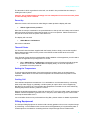
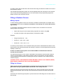
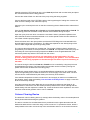
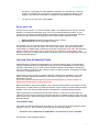
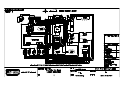
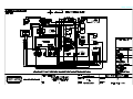
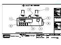
POLYTEST
Product User Manual
Advanced Auto Density
Gradient Column
Copyright (C) 1998 All Rights Reserved
Issue 2 v1.05
Revised July 2007
RAY-RAN TEST EQUIPMENT LTD
Kelsey Close • Attleborough Fields Industrial Estate
Nuneaton • Warwickshire • CV11 6RS • United Kingdom
Tel : +44 (0)24 7634 2002 • Fax : +44 (0)24 7664 1670
E-Mail : [email protected]
Web Site : http://www.ray-ran.com
www.ray-ran.com
POLYMER TEST EQUIPMENT FOR WORLD WIDE QUALITY
CONTROL
Density Gradient Column
CONTENTS
User Manual.......................................................................................................4
Description of the Apparatus ...........................................................................4
Lifting & Installation..........................................................................................4
•
Power Up..................................................................................................5
•
Thermal Printer.........................................................................................5
•
Setting the Temperature...........................................................................5
•
Cooling Coil ..............................................................................................5
Filling Equipment ..............................................................................................5
Filling the Gradient Column .............................................................................6
•
Mixing Liquids...........................................................................................6
•
Filling the Column.....................................................................................6
Column Clearing Device ...................................................................................7
Using the Columns Automatic Measuring System ........................................8
•
Column Calibration ....................................................................................8
•
Sample Density Readings .........................................................................9
•
Check a Calibrated Column.......................................................................9
•
Errors due to Air ......................................................................................10
Use and Care of Density Floats .....................................................................10
•
Correction Factor.....................................................................................10
Care of the Density Column ...........................................................................11
Solutions and Densities .................................................................................12
Densities of Aqueous Organic Solutions Table ...........................................13
Diagrams .........................................................................................................14
•
Wiring Diagram 240 Volts ........................................................................14
2
Density Gradient Column
•
Wiring Diagram 110 Volts ........................................................................15
•
Filling System ..........................................................................................16
Ray-Ran Products ...........................................................................................17
3
Density Gradient Column
User Manual
Thank you for purchasing the Ray-Ran Auto Density Gradient Apparatus. Please read this
manual before operation. If you have any questions regarding the installation and operation of
the equipment, please contact Ray-Ran for assistance.
Description of The Machine
The Gradient Column Method accurately determines the density of small solid specimens in any
form eg. sheet, film, granule, powder etc.
The glass test tube is filled with two miscible solutions. The resulting mixture varies at a linear
rate with the lowest density at the top of the tube and the highest density at the bottom.
Calibrated glass marker floats of precisely known densities are introduced into the column and
sink to a point where the density matches that of the solution.
The apparatus uses a linear encoder to calibrate the gradient of the column. This is achieved by
focusing the optical microscope onto the centre of the calibrated float and entering the floats
density value into the microprocessor.
A sample of unknown density is introduced to the column and allowed to reach equilibrium. The
linear encoder measures the samples position in the tube relative to the marker floats which is
then displayed on the LCD as its density.
Depending on the columns use or age the density distribution of the gradient can remain stable
for up to 40 weeks.
For additional information refer to the test standard ISO 1183
Lifting & Installation
It is recommended The Density Column be lifted by two people and placed on a level, robust
bench at a height that is suitable for the operator to take accurate measurements. The
apparatus should be shielded from direct sunlight to prevent algae growth within the column. If
the room temperature is above 23° C the column should be within reach of a mains water
supply and waste or connected to a pumped cooling device.
Electrical Characteristics
240 50hz
110 60hz
5amp
Please ensure that the mains cable plug is fitted into an electrical safety device before turning
on the apparatus. This Appliance Must Be Earthed
Caution! Please do not turn on apparatus until the water jacket has been filled with fluid
as this may damage the water pump.
The water jacket may be filled from the top of the column through one of the test tube holes.
The use of de-ionised water in addition to 100ml of ethylene glycol type antifreeze will keep the
jacket clean and algae free. The liquid should be Luke warm to reduce the risk of thermal shock
and stress to the water jackets material.
Caution! Please pay great attention to the water mark levels shown on the front of the
main cabinet. These levels are marked to show the water fill level of the jacket relative to
the number of test tubes to be used. Please do not fill above these levels as excess water
may spill into the rear of the cabinet.
4
Density Gradient Column
The test tube in which a gradient is to be built, can be left in situ provided the tube clamp is
holding the tube in place.
Caution! Any graduated tubes left empty and not clamped will rise when the water jacket
is filled and may cause a hazard.
Power Up
When the machine is first turned on after filling the water jacket the display will read
•
<Move sight to home position>
Move the microscope crosshead in an upward direction to the top rail until a beep can be heard.
When the beep sounds this means that the sight is in its home position. Please note that this
only has to be done when the power is first turned on.
The display will now read
•
<Main Menu> <Calibration>
See column calibration.
Thermal Printer
If a Thermal Printer has been supplied with the Density Column simply connect the supplied
RS232 data transfer cable from the printer to the RS232 socket located at the rear of the
columns control box.
If the Thermal Printer has been supplied after initial installation of the apparatus you will need to
configure the apparatus for printing mode. To do this,
•
When <Main Menu> <Calibration> is displayed on the LCD press and hold the green
button for 10 seconds. <Printer On> will display briefly on the LCD. Repeat the
procedure to turn the printer off.
Setting the Temperature
To set the required temperature of the jacket press the up/down keys on the temperature
controller. Please allow 30 minutes for the temperature of the fluid inside the jacket to reach
equilibrium.
Cooling Coil
If the ambient temperature exceeds 20° C it is advisable to cool the water bath by connecting
either a tap water supply or preferably a chiller system (an option which can be supplied by
Ray-Ran) to the cooling coil. This will allow the temperature controller to work more effectively
ensuring temperature accuracy within the column.
Reduce the ambient temperature of the bath to below 20oC using the chiller system and leave to
stabilise. Set the temperature controller to 23oC set point, which will then go into control mode
and keep the water bath at 23oC
Low cost Chiller Units can be purchased from Ray-Ran, please contact for details & quotations.
Filling Equipment
The Pumped Filling Equipment is used to build a density gradient column over a required range
by connecting 2 conical flasks which are secured to the apparatus by a Polycarbonate plate. A
screwed pinchcock is fitted for controlling the flow of liquid through silicone rubber tubes.
5
Density Gradient Column
The filing system and the flask stirrer are turned on/off using the switches located on the front of
the electronics cabinet.
If the standard pumped filling system is to be used please follow the instructions in this manual.
If the microprocessor filling equipment is to be used instead of the pumped filling equipment
please consult its own technical manual.
Filling a Gradient Column
Mixing Liquids
To build a density gradient column two solutions of suitable miscible liquids are needed. 860cc
of each liquid will be required. Solution A should be a low density and solution B should be
high density.
To calculate the densities needed to build a successful column first take into account the
density range to be covered.
•
Reduce the range from the lowest density required from solution A by 20%
•
Increase the range to the highest density of solution B by 30%
Example:
•
Range required 0.90 – 1.00
•
Solution A = 0.90 - 20% = 0.88
•
Solution B = 1.00 + 30% = 1.03
The density of the solutions can be estimated with hydrometers, standard dilution tables or with
density floats. (the lowest float should sink steadily in solution A and the highest float should rise
steadily in solution B)
A Table of suitable liquid systems and an Ethanol/Water standard dilution table are
include with this manual.
If a water based system is to be used it is advisable to de-aerate the solutions after mixing by
vacuum or gentle heating. If the heating method is used it is important to note the suppliers
recommendations and comments on fumes given off by the solutions. Each solution must be
mixed thoroughly.
PLEASE CONSULT THE MANUFACTURERS MATERIAL SAFETY DATA SHEETS (MSDS)
WHEN USING CHEMICALS AND COSHH REQUIREMENTS.
Filling the Column
Please ensure that the sweep baskets are placed into the test tubes before filling the
glass tubes with your gradient liquid and that the cord is safely secured.
Empty the tube and rinse with alcohol and allow too dry. Return the tube back into the water
jacket and fit the plastic cap to the top of the tube and secure the tube in place with the tube
clamp.
Insert the PTFE tube through the plastic cap and ensure the PTFE filling tube is at the bottom of
the test tube.
6
Density Gradient Column
Carefully place the PTFE stirrer bar into conical flask A (the flask with 2 outlet holes) and place
the connected flasks onto the filling platform.
Connect the outlet of flask A to the inlet of the pump using the tubing supplied.
Connect the flared end of the PTFE filling tube to the longest length of tubing then connect the
other end to the tubing to the outlet of the pump.
Close the nylon screwed pinchcock on the tube connecting the two flasks and the outlet tube of
flask A.
Pour the low density solution A into flask A and the high density solution B into flask B. Fit
the retaining plate over the flasks to keep the flask secure before stirring the liquid.
Open the nylon pinchcock which connects the two flasks. When hydrostatic equilibrium has
been reached the stirrer should be switched on for a short period to allow the two solutions to
mix in flask A before pumping begins.
Ensure all valves are in the open position and that the PTFE filling tube is situated within the
test tube before the pump is switched on. The filling rate depends on the density range of the
column. Wider ranges will require longer filling times.
The columns test tube will fill at a constant rate. The mixture of fluids in flask A will become
progressively more dense as the liquid enters from flask B. It is important to leave the pump on
until nearly all of the liquid has been pumped from flask A. Once the graduated tube is full,
remove the plastic cap and the PTFE tube from the column.
Caution! Turn the pump and stirrer off, immediately as the flasks empty. This will
prevent air being pump into the column and destroying the gradient. It is recommended
that after use the filling equipment is flushed through with water to prevent hardening of
the tubes
The rate of mixing the fluid from Flask A to Flask B can be controlled by using the pinchcock
located between the flasks. The Rate of filling the test tube can be increase by turning the
speed control switch located next to the filling pump.
Wide density ranges where there is a considerable difference between the two solutions will
require a longer filling time to allow the solution to mix thoroughly in the stirrer flask. The flow
into the column is also affected by the density and viscosity of the solution.
If the ambient temperature is above or below 23°C and a supply of water is not available use
the equation shown under the heading “Use and Care of Density Floats” to apply a correction
factor to the density readings.
Once the test tubes have been filled with the correct density gradient wet the floats (in deionised water to remove air from the surface) and drop them into the column starting with the
lowest density first then replace the rubber cap. Leave the floats to reach equilibrium. Once this
has been achieved the gradient column can be calibrated.
Column Clearing Device
The automatic column clearing device (or sweep) clears the density column of test samples and
density floats without disturbing the gradient.
The device consists of a swivelled beam that is positioned over the glass test tubes with the
basket line attached to the main line using a screw connector. To operate the device, attach a
sweep basket to the main cord at the top of the swivel beam and turn on the switch located on
7
Density Gradient Column
the front panel of the electronics cabinet. Use the up/down switch to activate the sweep in the
direction required.
The motor is automatically switched off when the mesh basket reaches the top and bottom of
the tube. To change from one basket to another the line will need to be unscrewed and secured
to the top of the column tube so other baskets can be raised from the remaining tubes.
Please note that the baskets can only be changed between columns when they are at rest
in the bottom of the test tube.
When a column is to be cleared, attach the basket cord of the appropriate column to the
clearing device and press the switch into the up (raise) position. The device will rise slowly so
the gradient is not disturbed. When the basket reaches the top of the column it will automatically
switch off. Once the basket has reached the top, remove the test samples and the density floats
then return the basket to the bottom of the tube by pressing the switch into the down position.
Repeat the procedure to clear the remaining graduated tubes.
Using the Columns Automatic Measuring System
Column calibration
Caution! Please do not attempt to calibrate the column until the water temperature has
stabilised at 23 Deg C
To use the column correctly you must calibrate the column by entering the float value reference
into the microprocessor. To do this, ensure that the microscope sight is in the home position.
•
Display reads <Main Menu> <Calibration>. Press <Select>
•
Display reads <Which Column> <Column A>. Rotate the dial on the front panel to
select column B, C or Abort. If Abort is selected the display will default back to the main
menu. Once the column to be calibrated has been chosen press <Select>.
•
Display reads <Calibration Menu> <Calibrate Column>. Press <Select> to calibrate
the column or rotate the dial on the front panel to display <Check Calibration> or
<Abort>
•
Display reads <Calibration Mode> <Float 1> <Add Float>. Move the microscope sight
to the centre of the first float. The focus of the sight can be adjusted by rotating the knob
at the side of the microscope. When the centre of the float has been positioned against
the microscope cross hair select <Add Float>.
Caution! Please ensure that the microscope has been moved to the appropriate
float before selecting the <Add Float> button. If this is not done the reading will
not be stored and the calibration will have to be carried out again.
Enter the density of the float (from the issued calibration certificate) by rotating the dial
on the front panel then select <Enter>.
•
Display reads <Float 2> <Add Float>. To add another float, move the microscope sight
to the next float and select <Add Float>. Rotate the dial on the front panel to the
required density and select <Enter>.
•
Repeat the procedure until all the used floats in the column have been entered into the
microprocessor.
•
When all of the floats have been entered, rotate the dial on the front panel until the
display reads <End Cal> then press the green button.
8
Density Gradient Column
•
Display reads <Save Cal Data>. Press <Select> to save the calibration data to the
microprocessor or rotate the dial on the front panel to display <Continue Cal> if more
floats are to be added or <Abort Cal> to abort the calibration procedure.
•
When <Save Cal Data> is selected the display will read <Main Menu> <Calibration>.
Repeat the procedure to calibrate the other columns if required.
Sample Density Readings
When the column has been calibrated test samples should be thoroughly wetted before being
placed in the column. To aid identification, samples from sheet material should be cut with a
sharp blade into various shapes. The time required for the samples to reach equilibrium vary
with the type of sample. Granules usually reach maximum density within one hour of immersion
whereas thin films may require longer. Several height sightings should be taken until the sample
is stable. The density can then be measured.
•
Display reads <Main Menu> <Calibration>. Rotate the dial until <Test Samples> is
displayed, then press <Select>.
•
Display reads <Column A>. Rotate the dial on the front display to select the active
column you wish to read the sample densities from. When the column has been chosen
press <Select>.
•
Display reads <Sample 1>. Move the microscope sight to the centre of the first sample
and take the density reading from the display then select <Next>.
(If the thermal printer has been activated the display will read <Print> instead of
<Next>)
•
Display reads <Sample 2>. Move the microscope sight to the centre of the second
sample and take the density reading from the display then select <Next>.
•
•
Repeat the procedure for all the samples you wish to measure.
When you have finished taking your readings rotate the dial on the front panel until
<Exit> is displayed. Press the green button. Display reads <Main Menu>
<Calibration>.
•
Repeat the procedure to read sample densities from another column.
Check a calibrated column
The apparatus has the capability to check a calibrated column for errors which may cause the
gradient to break down and become un-reliable. This may be due to a change in atmospheric
conditions or simply the amount of time that the column has been in use. To check a calibrated
column,
•
Display reads <Main Menu> <Calibration>. Press <Select>
•
Display reads <Which Column> <Column A>. Rotate the dial on the front display to
select the column B, C or Abort. Press <Select>
•
Display reads <Calibration Menu> <Calibrate Column>. Rotate the dial on the front
display until the display reads <Check Calibration>. Press <Select>. If the wrong
column has been selected or you wish to exit the procedure rotate the dial until <Abort>
is displayed.
•
Display reads <Calibration Check> <Float No> and <Density>. Move the microscope
viewer to float 1. When the microscope is in range of the floats density the apparatus
9
Density Gradient Column
will “Beep”. The display will read <Float 1> followed by the float density. Check the
position of the float to see if its position is still relative to the density reading on the
display. If the float has moved then re-calibration of the gradient will be required.
•
To return to the main menu select <Exit>
Errors due to Air
A major source of errors, in columns containing water, is air absorbed in the solution, forming
bubbles on the floats and samples, which can be very small and difficult to detect. A cyclic
movement of the floats or samples usually indicates the presence of small bubbles. These air
bubbles can be prevented by de-gassing the two solutions before filling the column.
•
•
Ethanol solutions should be de-gassed by using a vacuum.
Salt solutions should be de-gassed by boiling.
If air bubbles form on the floats, remove the float from the column. This can be done using a
long thin piece of wire, with a ring at the end, bent at right angles. Once the float has been
removed dip it in distilled water containing a few drops of liquid soap, then return the float to the
column. Caution! This must be done carefully so the gradient is not disturbed. If the
bubbles persist after re-wetting the samples or floats the column should be built again taking the
recommended precautions.
Use and Care of density Floats
Calibrated Density Floats are manufactured from coloured soda/lime glass. No appreciable
change in density has been recorded after several years use in water/ethanol or hydrocarbon
solutions. If the floats are to be used in strong alkaline solutions it is advisable to periodically
check one float by comparison with a float not used in a alkaline solution. Alternatively Ray-Ran
can offer a re-calibration service.
Although the floats come with a complete calibration certificate it is advisable to record the
colour, markings, diameter and density of each float in a register or log book to ease the
identification process.
Do not use metallic measuring devices such as micrometers or vernier callipers to
measure the floats unless of the plastic type.
Before the floats are put into the gradient column they should be wetted in the residue from the
filling device or similar solution to prevent air bubbles. Finger marks can make wetting the floats
difficult. If this is the case the floats should be cleaned with a suitable detergent solution.
After long periods of use the floats may become covered in a thin film of material from the
samples. This film can be removed by immersing the float in a diluted solution of nitric acid. The
floats should not be cleaned with paper towels or laboratory wipes as repeated rubbing can alter
the floats density.
Correction Factor
If the floats are used at temperatures other than 23° C a correction should be applied to obtain
maximum accuracy. The correction is obtained with the following equation,
Correction for 1°C difference in temperature = Float density at 23°C x 0.000028
This equation is then applied as follows,
10
Density Gradient Column
Below 23°C = Stated density of Float + Correction for each °C difference in temperature
Above 23°C = Stated density of Float - Correction for each °C difference in temperature
Care of the Density Column
Some solutions can damage the Perspex water jacket and acrylic finishes. It is therefore
important that all spills are mopped up immediately. The water jacket should not be cleaned
with acetone or similar solvents, which will cause stresses and cracking. A mild detergent
solution should be used for general cleaning. More persistent stains and small scratches can be
removed with an Aerosol Acrylic Polish.
After opening the pinchcock on the filling platform, check the interconnecting tube for air
bubbles, these can be removed by momentarily lifting one flask. After use, disconnect the filling
tube, remove the flasks from the platform, rinse them with water and allow to dry. They should
be stored in a safe place with the connecting tubes attached.
11
Density Gradient Column
Solutions and Densities
Solution
Density Range KG/M³
Methanol – Benzyl – Alcohol
800 – 920
Isopropanol – water
790 – 1000
Isopropanol – Diethylene Glycol
790 – 1000
Ethanol – Carbon Tetrachloride
790 – 1590
Ethanol – Water
790 – 1000
Toluene – Carbon Tetrachloride
870 – 1590
Water – Calcium Nitrate
1000 – 1450
Water – Potassium Iodide
1000 – 1600
Water – Sodium Bromide
1000 – 1600
Zinc Chloride – Ethanol – Water
800 – 1700
Carbon Tetrachloride – 1,3 –Dibrompropane
1600 – 1990
1,3 –Dibrompropane – Ethanol Bromide
1990 – 2190
Ethylene Bromoform
2180 – 2890
Carbon Tetrachloride - Bromoform
1600 - 2890
The following may also be used in various mixtures
n-octane
700
Dimethylformahide
940
Tetrachlorethane
1590
Ethyl Iodide
1930
Methylene Iodide
3330
WARNING
Many of these liquids are TOXIC and/or inflammable. Attention should be paid to all
appropriate safety precautions and Safety Data Sheets, which should be obtained from
the chemical suppliers. COSHH regulations should be observed at all times.
12
Density Gradient Column
Densities of Aqueous Organic Solutions
Ethyl Alcohol (C2H3 OH)
%
10°c
15°c
20°c
25°c
30°c
35°c
40°c
%
10°c
15°c
20°c
25°c
30°c
35°c
40°c
0
.99973
.99913
.99823
.99708
.99568
.99406
.99225
50
.92126
.91776
.91384
.90985
.90580
.90168
.89750
1
2
3
4
5
765
602
426
258
098
725
542
365
195
032
636
453
275
103
.98938
520
336
157
.98984
817
379
194
014
.98839
670
217
031
.98849
672
501
034
.98846
663
485
311
51
52
53
54
55
.91943
723
502
279
055
555
333
110
.90885
659
160
.90936
711
485
258
760
534
307
079
.89850
353
125
.89896
667
437
.89940
710
479
248
016
519
288
056
.88823
589
6
7
8
9
10
.98946
801
660
524
393
.98877
729
584
442
304
780
62
478
331
187
656
509
346
193
043
507
347
189
031
.97875
335
172
009
.97846
685
142
.97978
808
641
475
56
57
58
59
60
.90831
607
381
154
.89927
433
207
.89980
752
523
031
.89803
574
344
113
621
392
162
.88931
699
206
.88975
744
512
278
.88784
552
319
085
.87851
356
122
.87888
653
417
11
12
13
14
15
267
145
026
.97911
800
171
041
.97914
790
669
047
.97910
775
643
514
.97897
753
611
472
334
723
573
424
278
133
527
371
216
063
.96911
312
150
.96989
829
670
61
62
63
64
65
698
468
237
006
.88774
293
062
.88830
597
364
.88882
650
417
183
.87948
446
233
.87998
763
527
044
.87809
574
337
100
615
379
142
.86905
667
180
.86943
705
466
227
16
17
18
19
20
692
583
473
363
252
552
433
313
191
068
387
259
129
.96997
864
199
062
.96923
782
639
.96990
844
697
547
395
760
607
452
294
134
512
352
189
023
.95856
66
67
68
69
70
541
308
074
.87839
602
130
.87895
660
424
187
713
477
241
004
.86766
291
054
.86817
579
340
.86863
625
387
148
.85908
429
190
.85950
710
470
.85987
747
407
266
025
21
22
23
24
25
139
024
.96907
787
665
.96944
818
689
558
424
729
592
453
312
168
495
348
199
048
.95895
242
087
.95929
769
607
.95973
809
643
476
306
687
516
343
168
.94991
71
72
73
74
75
365
127
.86888
648
408
.86949
710
470
229
.85988
527
287
047
.85806
564
100
.85859
618
376
134
667
426
184
.84941
698
228
.84986
743
500
257
.84783
540
297
053
.83809
26
27
28
29
30
539
406
268
125
.95977
287
144
.95996
844
686
020
.95867
710
548
382
738
576
410
241
067
442
272
098
.94922
741
133
.94955
774
590
403
810
625
438
248
055
76
77
78
79
80
168
.85927
685
442
197
747
505
262
018
.84772
322
079
.84835
590
344
.84891
647
403
158
.83911
455
211
.83966
720
473
013
.83768
523
277
029
564
319
074
.82827
578
31
32
33
34
35
823
665
502
334
162
524
357
186
011
.94832
212
038
.94860
679
494
.94890
709
525
337
146
557
370
180
.93986
790
214
021
.93825
626
425
.93860
662
461
257
051
81
82
83
84
85
.84950
702
453
203
.83951
525
277
028
.83777
525
096
.83848
599
348
095
664
415
164
.82913
660
224
.82974
724
473
220
.82780
530
279
027
.81774
329
079
.81828
576
322
36
37
38
39
40
.94986
805
620
431
238
650
464
273
079
.93882
306
114
.93919
720
518
.93952
756
556
353
148
591
390
186
.92979
770
221
016
.92808
597
385
.92843
634
422
208
.91992
86
87
88
89
90
697
441
181
.82919
654
271
014
.82754
492
227
.82840
583
323
062
.81797
405
148
.81888
620
362
.81965
708
448
186
.80922
519
262
003
.80742
478
067
.80811
552
291
028
41
42
43
44
45
042
.93842
639
433
226
682
476
271
062
.92852
314
107
.92897
685
472
.92940
729
516
301
035
558
344
128
.91910
692
170
.91952
733
513
291
774
554
332
108
.90884
91
92
93
94
95
386
114
.81839
561
278
.81959
688
413
134
.80852
529
257
.80983
705
424
094
.80823
549
272
.9991
655
384
111
.79835
555
211
.79941
669
393
114
.79761
491
220
.78947
670
46
47
017
.92806
640
426
257
041
.91888
649
472
250
069
.90845
660
434
96
97
.80991
698
566
274
138
.79846
706
415
271
.78981
.78831
542
388
100
13
Density Gradient Column
48
49
593
379
211
.91995
.91823
604
429
208
028
.90805
621
396
207
.89979
98
99
100
399
094
.79784
.79975
670
368
547
243
.78934
117
.78814
506
684
382
075
247
.77946
641
14
.77806
507
203
14
Density Gradient Column
16
Density Gradient Column
17
Ray Ran Products and Services
Raw Material Evaluation
Code
RR/5MBA
RR/5SA
RR/5MPCA
RR/DGA
RR/BDA
RR/ADV
RR/VOY
RR/DIS
RR/MB
Product
Model 5MBA Melt Flow Indexer
Model 5SA Melt Flow Indexer
Model 5MPCA Melt Flow Indexer
3 Column Density Gradient Apparatus
Apparent Bulk Density Apparatus
Adventurer Balance (Readability 0.1mg) 110/260g Capacity
Voyager Balance (Readability 0.1mg) 62/410/100g Capacity
Discovery Balance (Readability 0.1mg) 110/310g Capacity
Moisture Balance (Readability 0.1%, 0.05%, 0.01%) 110/35/45g Cap
Sample Preparation
Code
RR/TSMP2
RR/HCP
RR/PCP
RR/NC
RR/CNC
RR/CNC 2
TSC + Standard
Product
Model 2 Test Sample Injection Moulding Apparatus
Hand Operated Test Sample Cutting Press
Pneumatically Operated Test Sample Cutting Press
Auto Cycle Test sample Notching Cutter
Test Sample Profile Cutter
Test Sample Profile Cutter - Larger
Test Sample Cutters
Sample Testing
Code
RR/HDV2
RR/HDV4
RR/HDV6
RR/TAA
RR/LTB
RR/ESC
RR/FSL
RR/FSHP
RR/IMT
RR/FWT
RR/FD
RR/ETT
RR/FT
RR/M
D202
B202
WS777
Product
2 Station HDT/Vicat Softening Point Apparatus
4 Station HDT/Vicat Softening Point Apparatus
6 Station HDT/Vicat Softening Point Apparatus
Thermal Ageing Apparatus
Low Temperature Brittleness Tester
Environmental Stress Cracking Apparatus
Unrestrained Linear Thermal Film Shrinkage Apparatus
Hot Plate Film Shrinkage Apparatus
Universal Pendulum Impact Tester
Falling Weight Impact Tester
Falling Dart Impact Tester
Advanced Elmendorf Tear Tester
Static And Dynamic Friction Tester
Universal Tensile Tester – Various Capacity
Digital Handheld Durometer
Analogue Handheld Durometer
Analogue & Digital Durometer Workstations
17