1
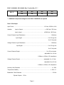
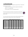
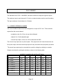
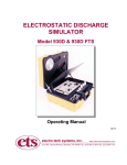
USER’S MANUAL
DUAL FEEDBACK ISOLATOR with CURRENT LOOP OUTPUT
EU-10099G SERIES
DYNAPOWER INVENTORY NUMBER
EUG-7-100990006
EUG-7-100990007
DYNAPOWER CORPORATION
85 MEADOWLAND DRIVE
SOUTH BURLINGTON, VERMONT 05403
PHONE: 802-860-7200
TOLL FREE: 800-292-6792
FAX: 802-652-1371
www.dynapower.com
[email protected]
This EUG-7-100990006 has been designed to be a fit, form, and function replacement for :
EUG-7-100990002, (EU-10099G, Rev. B)
EUG-7-100990003, (EU-10099G, Rev. C)
EUG-7-100990004, (EU-10099G, Rev. D)
The Isolator functions are changed by moving two jumpers.
EUG-7-100990006 Jumper Settings
Circuit
Replaced
JP1
JP2
JP3
JP4
EUG-7-100990002
N
Y
N
Y
EUG-7-100990003
Y
N
N
Y
EUG-7-100990004
Y
N
Y
N
For incorporation into new power supply designs, a Configuration will be used.
EUG-7-100990006 Jumper Settings
JP1
JP2
JP3
JP4
Configuration B
N
Y
N
Y
Configuration C
Y
N
N
Y
Configuration D
Y
N
Y
N
* An EUG-7-100990006 cannot be configured to be an EUG-7-100990005.
Component changes on the EUG-7-100990006 are also required.
SUMMARY
EUG-7-100990002
EUG-7-100990003
EUG-7-100990004
EUG-7-100990005*
Configuration B
Configuration C
Configuration D
EUG-7-100990007*
Jumper Setting
Jumper Setting
Jumper Setting
Jumper Setting
JP1
JP2
JP3
JP4
JP1
JP2
JP3
JP4
JP1
JP2
JP3
JP4
JP1
JP2
JP3
JP4
N
Y
N
Y
Y
N
Y
N
Y
N
N
Y
N
Y
N
Y
INPUTS
Terminal
13(+) - 12
0 – 50 mv
0 – 50 mv
0 – 50 mv
0 – 2.5 V
16(+) - 15
0 – 2.5 V
0 – 2.5 V
0 – 2.5 V
0 – 2.5 V
OUTPUTS
Terminal
6
Current
Feedback
0 - (-)50mv, Absolute
0 - (±)50mv, Bi-Polar
0- (-)50mv, Absolute
0 - (-)50mv, Absolute
0 - (-)10v, Absolute
0 - (±)10v, Bi-Polar
0- (±)10v, Bi-Polar
0 - (-)10v, Absolute
7
Voltage
Feedback
8
0-20 ma, Absolute
0-20 ma, Unipolar
0-20 ma, Unipolar
0-20 ma, Absolute
Voltage
Feedback
4-20 ma, Absolute
4-20 ma, Uniploar
4-20 ma, Uniploar
4-20 ma, Absolute
10
0-20 ma, Absolute
0-20 ma, Unipolar
0-20 ma, Absolute
0-20 ma, Absolute
Current
Feedback
4-20 ma, Absolute
4-20 ma, Unipolar
4-20 ma, Absolute
4-20 ma, Absolute
17
0 – (±)10v, Bi-Polar
0 – (±)10v, Bi-Polar
0 –(±)10v, Bi-Polar
0 – (±)10v, Bi-Polar
Filtered
Filtered
Filtered
Filtered
0 – (±)10v, Bi-Polar
0 – (±)10v, Bi-Polar
0 –(±)10v, Bi-Polar
0 – (±)10v, Bi-Polar
Filtered
Filtered
Filtered
Filtered
Voltage
Feedback
19
Current
Feedback
STANDARD
CONFIGURATION
FOR REVERSING
OR BATTERY
CHG/DISCHG
SUPPLIES
* An EUG-7-100990006 cannot be configured to be an EUG-7-100990007.
Component changes on the EUG-7-100990006 are also required.
CONTENTS
1 .............................................................................................................................. Specifications
2 .................................................................................................................................. Description
3 ..................................................................................................................... Terminal Functions
4 ................................................................................................................................ Adjustments
5 .................................................................................................................................. Bench Test
6 ...................................................................................................................... Field Adjustments
7 ..................................................................................................................... EUG-7-100990007
Word File:099OGFM.DOC
December 2005
1. SPECIFICATIONS
EUG-7-100990006 (EU-10099G, Rev. F) Configuration B
JP1
JP2
JP2
JP4
ON
ON
ON
ON
REV. B
Input Power ............................................................................................. 115 Vac, 50/60 Hz, 6VA
Isolation:
Input to Output ................................................................... ± 1000 Vpk, 750 Vrms
Input to Input ................................................................. ± 2000 Vpk, 1500 Vrms.
Current Channel: Input Resistance ............................................................................... 100 ohms
Input Signal ................................................................................ 0-50 avg dcmv
0-200 dcmv peak
Voltage Channel: Input Resistance ................................................................................ 10 Kohms
Input Signal ............................................................................. 0 to 2.5 avg Vdc
0 to 5 Vdc peak
Current Channel Output ................................................................................. 0 to -50 mv dc abs.
adjustable 0 to ±10 vdc
0-20ma or 4-20ma, 10V compliance
Voltage Channel Output ................................................................... adjustable 0 to -10 Vdc abs.
adjustable 0 to ±10 Vdc
0-20ma or 4-20ma, 10V compliance
Linearity, both Channels ................................................................................................. < ± .05%
Temperature Stability ................................................................................................. ± .02% /°C.
Bandwidth -
Both Channels ........................................................................................... 2.5 Khz
Bipolar Outputs ............................................................................................ 20 Hz
Page 1
EUG-7-100990006 (EU-10099G, Rev. F) Configuration C
JP1
JP2
JP2
JP4
ON
ON
ON
ON
REV. C
Input Power ............................................................................................. 115 Vac, 50/60 Hz, 6VA
Isolation:
Input to Output ................................................................... ± 1000 Vpk, 750 Vrms
Input to Input ................................................................. ± 2000 Vpk, 1500 Vrms.
Current Channel: Input Resistance ............................................................................... 100 ohms
Input Signal ................................................................................ 0-50 avg dcmv
0-200 dcmv peak
Voltage Channel: Input Resistance ................................................................................ 10 Kohms
Input Signal ............................................................................. 0 to 2.5 avg Vdc
0 to 5 Vdc peak
Current Channel Output ......................................................................................... 0 to -50 mv dc
adjustable 0 to ±10 vdc
0-20ma or 4-20ma, 10V compliance
Voltage Channel Output ........................................................................... adjustable 0 to -10 Vdc
adjustable 0 to ±10 Vdc
0-20ma or 4-20ma, 10V compliance
Linearity, both Channels ................................................................................................. < ± .05%
Temperature Stability ................................................................................................. ± .02% /°C.
Bandwidth - Both Channels .............................................................................................. 2.5 Khz
Bipolar Outputs ................................................................................................ 20 Hz
Page 2
EUG-7-100990006 (EU-10099G, Rev. F) Cofiguration D
JP1
JP2
JP2
JP4
ON
ON
ON
ON
REV. D
Input Power ............................................................................................. 115 Vac, 50/60 Hz, 6VA
Isolation:
Input to Output ................................................................... ± 1000 Vpk, 750 Vrms
Input to Input ................................................................. ± 2000 Vpk, 1500 Vrms.
Current Channel: Input Resistance ............................................................................... 100 ohms
Input Signal ................................................................................ 0-50 avg dcmv
0-200 dcmv peak
Voltage Channel: Input Resistance ................................................................................ 10 Kohms
Input Signal ............................................................................. 0 to 2.5 avg Vdc
0 to 5 Vdc peak
Current Channel Output ................................................................................. 0 to -50 mv dc abs.
adjustable 0 to ±10 vdc
0-20ma or 4-20ma, 10V compliance
Voltage Channel Output ......................................................................... adjustable 0 to -10 Vdc .
adjustable 0 to ±10 Vdc
0-20ma or 4-20ma, 10V compliance
Linearity, both Channels ................................................................................................. < ± .05%
Temperature Stability ................................................................................................. ± .02% /°C.
Bandwidth - Both Channels .............................................................................................. 2.5 Khz
Bipolar Outputs
20 Hz
Page 3
EUG-7-100990006 (EU-10099G, Rev. F) set for Rev. E ***
JP1
JP2
JP2
JP4
ON
ON
ON
ON
REV. E
*** Additional component changes on the EUG-7-100990006 are required
Dual 2.5 Volt Input
Input Power ............................................................................................. 115 Vac, 50/60 Hz, 6VA
Isolation:
Input to Output ................................................................... ± 1000 Vpk, 750 Vrms
Input to Input ................................................................. ± 2000 Vpk, 1500 Vrms.
Current Channel: Input Resistance ............................................................................... 10 Kohms
Input Signal .............................................................................. 0 to 2.5 avg Vdc
0 to 5 Vdc peak
Voltage Channel: Input Resistance ................................................................................ 10 Kohms
Input Signal ............................................................................. 0 to 2.5 avg Vdc
0 to 5 Vdc peak
Current Channel Output ................................................................................. 0 to -50 mv dc abs.
adjustable 0 to ±10 vdc
0-20ma or 4-20ma, 10V compliance
Voltage Channel Output ......................................................................... adjustable 0 to -10 Vdc .
adjustable 0 to ±10 Vdc
0-20ma or 4-20ma, 10V compliance
Linearity, both Channels ................................................................................................. < ± .05%
Temperature Stability ................................................................................................. ± .02% /°C.
Bandwidth - Both Channels .............................................................................................. 2.5 Khz
Bipolar Outputs
20 Hz
Page 4
DYNAPOWER CORPORATION
DUAL FEEDBACK ISOLATOR with CURRENT LOOP OUTPUT
2. DESCRIPTION
Most regulator circuits used in Dynapower power supplies require current feedback signal from
a 50 mv shunt and a higher level voltage feedback signal from the output bus.
Also interfaced to the regulator circuits may be signals from external equipment. The regulators
and external equipment are thus connected directly to one of the power supply output busses.
It is advantageous to isolate the power supply output bus from the electronic regulating and
monitoring circuits. To this end, the Dual Feedback Isolator Circuit may be used. The circuit
has large bandwidth, excellent linearity and stability, making it suitable for closed loop
applications.
The circuit has two inputs which are isolated from each other. One channel is used as the
current feedback channel and the other is used as the voltage feedback channel.
The following descriptions do not apply to an EUG-7-100990007, see the
description starting at Page 16 of this Manual.
Page 5
2.1 CURRENT FEEDBACK CHANNEL
The current feedback channel has been designed for an input of 0-50 mv dc. There are three
outputs from the current channel:
an absolute value 0 to -50 mv dc to connect to a regulator (see User's Manual)
a bipolar 0 to 10 with adjustable gain
a current loop output, 4-20 ma or 0-20 ma selected with SW2
The Current Loop output can only be uni-polar. If the jumpers for the Current channel
are set for bi-polar output, then the current loop output will only work when the input
polarity is positive.
The current loop output may be converted into a positive voltage by switching in a resistor.
Outputs are selected by setting dip switches as shown in the following table.
CURRENT CHANNEL DIP SWITCH SETTINGS
OUTPUT
SW2-1
SW2-2
SW2-3
SW2-4
SW2-5
SW2-6
0 - 20 MA
ON
ON
OFF
OFF
OFF
OFF
4 - 20 MA
OFF
OFF
ON
OFF
OFF
OFF
0 - 2 VOLTS
ON
ON
OFF
ON
OFF
OFF
0 - 5 VOLTS
ON
ON
OFF
OFF
ON
OFF
0 - 10 VOLTS
ON
ON
OFF
OFF
OFF
ON
.4 - 2 VOLTS
OFF
OFF
ON
ON
OFF
OFF
1 - 5 VOLTS
OFF
OFF
ON
OFF
ON
OFF
2 - 10 VOLTS
OFF
OFF
ON
OFF
OFF
ON
Page 6
2.2 VOLTAGE FEEDBACK CHANNEL
The voltage channel has been designed for an input of 0-2.5 Vdc. A voltage dropping resistor
must be connected in series with one of the input terminals. The input resistance of the voltage
is 10 Kohms.
There are three outputs from the voltage channel:
an absolute value 0 to -10 volts dc with adjustable gain
a bipolar 0 to 10 volts with adjustable gain
a current loop output, 4-20 ma or 0-20 ma selected with SW1
The Current Loop output can only be uni-polar. If the jumpers for the Current
channel are set for bi-polar output, then the current loop output will only work when
the input polarity is positive.
The current loop output may be converted into a positive voltage by switching in a resistor.
Outputs are selected by dip switch settings as shown in the following table.
VOLTAGE CHANNEL DIP SWITCH SETTINGS
OUTPUT
SW1-1
SW1-2
SW1-3
SW1-4
SW1-5
SW1-6
0 - 20 MA
ON
ON
OFF
OFF
OFF
OFF
4 - 20 MA
OFF
OFF
ON
OFF
OFF
OFF
0 - 2 VOLTS
ON
ON
OFF
ON
OFF
OFF
0 - 5 VOLTS
ON
ON
OFF
OFF
ON
OFF
0 - 10 VOLTS
ON
ON
OFF
OFF
OFF
ON
.4 - 2 VOLTS
OFF
OFF
ON
ON
OFF
OFF
1 - 5 VOLTS
OFF
OFF
ON
OFF
ON
OFF
2 - 10 VOLTS
OFF
OFF
ON
OFF
OFF
OFF
Page 7
3. TERMINAL FUNCTIONS
Terminal
Function
1
115 Vac power
2
115 Vac power
3
Power Supply Common
4
+ 15 Volt Power Supply Output
5
- 15 Volt Power Supply Output
6
50 MV Current Signal (absolute negative or bi-polar)
Jumper Setting
7
Voltage Signal (absolute negative or bi-polar)
Jumper Setting
8
Voltage Channel Current Loop Out
9
Output Signal Common
10
Current Channel Current Loop Out
11
N/C
12
Voltage Channel Input (-)
13
Voltage Channel Input (+)
14
N/C
15
Current Channel Input (-)
16
Current Channel Input (+)
17
Voltage Channel Bi-polar Out
18
Output Signal Common
19
Current Channel Bi-polar Out
Page 8
115 VAC
1
115 VAC
2
COMM
3
+15 VDC
4
-15 VDC
CURR SIG OUT (50MV)
5
6
ON
ON
1
1
2
2
3
3
4
4
5
5
6
VOLT SIG OUT
VOLT CHAN CURR LOOP OUT
7
17
BI-POLAR VOLTAGE SIG
18
COMM
19
BI-POLAR CURRENT SIG
6
SW2
SW1
8
P1
OUTPUT SIG COMM
CURR CHAN CURR LOOP OUT
9
10
11
JP4
JP2
JP3
JP1
P2
P3
VOLT CHAN INPUT (-)
12
VOLT CHAN INPUT (+)
13
P7
P4
14
P5
CURR CHAN INPUT (-)
15
CURR CHAN INPUT (+)
16
P6
Page 9
4. ADJUSTMENTS
P1
adjusts current channel bi-polar output on terminal 19.
P2
adjusts voltage channel bi-polar output on terminal 17.
P3
adjusts voltage channel output on terminal 7.
P4
adjusts voltage channel current loop output on terminal 8.
P5
adjusts voltage channel offset.
P6
adjusts current channel offset.
P7
adjusts current channel current loop output on terminal 10.
Page 10
5. BENCH TEST
1.
Set voltage channel for 4 to 20 ma output.
Set current channel for 4 to 20 ma output.
JP1 – OFF
JP2 – ON
JP3 – OFF
JP4 - ON
2.
Measure voltage between terminal 4 and common terminal 3
Should be +15, ± .25 Vdc
3.
Measure voltage on terminal 5 and common terminal 3
Should be -15, ± .25 Vdc
4. Voltage Channel
Connect milli-ammeter in series with 100 ohms to terminal 8 and terminal 9
Current from terminal 8 should be 4.00 ma, adjust with P5.
Voltage on terminal 7 should be ± .01
Voltage on terminal 17 should be ± .01
Connect 2.50 Vdc to terminal 13 (+) and terminal 12.
Current from terminal 8, should be 20.00 ma, adjust with P4.
Voltage on terminal 7 should be -5.00, adjust with P3.
Voltage on terminal 17 should be +5.00, adjust with P2
Remove milli-ammeter
Page 11
5. Current Channel
Connect milli-ammeter in series with 100 ohms terminal 10 and terminal 9
Current from terminal 10 should be 4.00 ma, adjust with P6.
Voltage on terminal 19 should be ± .01 volts.
Voltage on terminal 6 should be ± .005 volts.
Connect 50.00 mv dc to terminal 16 (+) and 15.
Voltage on terminal 6 should be -50.0 mv
Current from terminal 10 should be 20.0 ma, adjust with P7.
Voltage on terminal 19 should be +5.00, adjust with P1.
Page 12
6. FIELD ADJUSTMENTS
The Isolator can be used to close the loop of the regulator controlling the power supply and at
the same time provide feedback to the User. Making adjustments to one function may affect the
other function, i.e. making adjustments for closed loop may affect feedback to the User and
making adjustments to User feedback may affect power supply setpoint.
If adjustments are to be made while the supply is running
Adjustment to the voltage feedback should be made with the power supply running in
constant current mode
Adjustments to the current feedback should be made with the power supply running in
constant voltage mode.
For voltage measurements, terminal 3 is common.
Voltage Channel
Power supply is OFF.
Connect milli-ammeter in series with terminal 8 and terminal 9
Current from terminal 8 should be 4.00 ma or 0.00 ma (depending on SW1switch settings),
adjust with P5.
Voltage on terminal 7 should be ± .01
Voltage on terminal 17 should be ± .01
Page 13
Turn supply ON, set output for constant current operation.
If feedback current is set for 0 - 20 ma, feedback current should be 20*(actual power
supply voltage)/(power supply voltage rating), adjust with P4.
If feedback current is set for 4 - 20 ma, feedback current should be 4 + 16*(actual power
supply voltage)/power supply voltage rating, adjust with P4.
Voltage on terminal 7 should be -5.00*(actual power supply voltage)/(power supply voltage
rating), adjust with P3. If the voltage from this terminal is used as the feedback voltage to a
regulator, then the power supply VOLT LIMIT control will have to be reset.
Voltage on terminal 17 should be +5.00*(actual power supply voltage)/(power supply voltage
rating), adjust with P2.
5. Current Channel
Power supply is OFF.
Connect milli-ammeter in series with terminal 9 and terminal 10
Current from terminal 10 should be 4.00 ma or 0.00 ma (depending on SW2 switch settings),
adjust with P6.
Voltage on terminal 6 should be ± .001
Voltage on terminal 19 should be ± .01
Turn supply ON, set output for constant voltage operation
If feedback current is set for 0 - 20 ma, feedback current should be 20*(actual power
supply current)/(power supply current rating), adjust with P7.
If feedback current is set for 4 - 20 ma, feedback current should be 4 + 16*(actual power
supply current)/(power supply current rating), adjust with P7.
Page 14
Voltage on terminal 6 should be -.050*(actual power supply current)/(power supply current
rating).
Voltage on terminal 19 should be +5.00*(actual power supply current)/(power supply current
rating), adjust with P1.
Note
The output voltages on terminal 17 and 19 are intended to be feedbacks to User equipment and
may be set to match the requirements of User equipment.
Page 15
EUG-7-100990007
The standard circuit, EUG-7-100990006, has been modified to accept two high level inputs.
The maximum input to each channel is 2.5 volts, an external resistor must be used for scaling.
The input resistance of each channel is 10 kohms.
2.1 CURRENT FEEDBACK CHANNEL
The current feedback channel has been designed for an input of 0-2.5 vdc. There are three
outputs from the current channel:
an absolute value 0 to -50 mv dc (see User's Manual)
a bipolar 0 to 10 with adjustable gain
a current loop output, 4-20 ma or 0-20 ma selected with SW2
The Current Loop output can only be uni-polar. If the jumpers for the Current channel are set
for bi-polar output, then the current loop output will only work when the input polarity is positive.
The current loop output may be converted into a positive voltage by switching in a resistor.
Outputs are selected by setting dip switches as shown in the following table.
CURRENT CHANNEL DIP SWITCH SETTINGS
OUTPUT
SW2-1
SW2-2
SW2-3
SW2-4
SW2-5
SW2-6
0 - 20 MA
ON
ON
OFF
OFF
OFF
OFF
4 - 20 MA
OFF
OFF
ON
OFF
OFF
OFF
0 - 2 VOLTS
ON
ON
OFF
ON
OFF
OFF
0 - 5 VOLTS
ON
ON
OFF
OFF
ON
OFF
0 - 10 VOLTS
ON
ON
OFF
OFF
OFF
ON
.4 - 2 VOLTS
OFF
OFF
ON
ON
OFF
OFF
1 - 5 VOLTS
OFF
OFF
ON
OFF
ON
OFF
2 - 10 VOLTS
OFF
OFF
ON
OFF
OFF
ON
Page 16
2.2 VOLTAGE FEEDBACK CHANNEL
The voltage channel has been designed for an input of 0-2.5 Vdc. A voltage dropping resistor
must be connected in series with one of the input terminals. The input resistance of the voltage
is 10 Kohms.
There are three outputs from the voltage channel:
an absolute value 0 to -10 volts dc with adjustable gain
a bipolar 0 to 10 volts with adjustable gain
a current loop output, 4-20 ma or 0-20 ma selected with SW1
The Current Loop output can only be uni-polar. If the jumpers for the Current
channel are set for bi-polar output, then the current loop output will only work when
the input polarity is positive.
The current loop output may be converted into a positive voltage by switching in a resistor.
Outputs are selected by dip switch settings as shown in the following table.
VOLTAGE CHANNEL DIP SWITCH SETTINGS
OUTPUT
SW1-1
SW1-2
SW1-3
SW1-4
SW1-5
SW1-6
0 - 20 MA
ON
ON
OFF
OFF
OFF
OFF
4 - 20 MA
OFF
OFF
ON
OFF
OFF
OFF
0 - 2 VOLTS
ON
ON
OFF
ON
OFF
OFF
0 - 5 VOLTS
ON
ON
OFF
OFF
ON
OFF
0 - 10 VOLTS
ON
ON
OFF
OFF
OFF
ON
.4 - 2 VOLTS
OFF
OFF
ON
ON
OFF
OFF
1 - 5 VOLTS
OFF
OFF
ON
OFF
ON
OFF
2 - 10 VOLTS
OFF
OFF
ON
OFF
OFF
OFF
Page 17