1
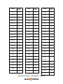
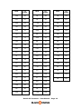
User Manual
Version History
1.1.5 – 4.25.2013 – Update
• Labeling/tooltip adjustments/standardizing
1.1.4 – 11.05.2012 – Update
• "Value out of range" bug fixed
• Labeling updates based on customer feedback. "CV2 Mix" is now "CV2 Influence",
"Filtered Split" is now "Threshold Switch", "Smooth" is now "Switch Smooth", Static
"Enable" is now "Replace CV Out"
• Signal flow chart updated on back of device to be clearer.
• Static knob is now continuous output through dedicated CV output connection port.
Allows generated CV signal to act independently of the main CV manipulation
section.
• Midi Note output
1.1.3 – 10.18.2012 – Initial Release
ReVolt CV Processor – User Manual – Page 1
CV Metering
As a CV meter ReVolt allows you to see the values and motion of the CV signals
being handled through the digital readout and analog voltmeter displays. The digital
readouts are useful for seeing the precise values you’re working with, and the analog
voltmeter gives you a visual indicator of the movement and range of your signals.
The metering capabilities are useful for the advanced Reason user as they provide
precise numeric information not previously available in the Reason rack (the DDL-1
trick did not display negative values). But the primary motivation for these displays
was one of education. The concept of CV can be confusing for new Reason users, and
having the digital and analog displays can greatly accelerate the learning process.
Even for the Reason veteran, knowing which device knobs/sliders are non-linear and
how steep their value ramping is can be valuable information that was previously
just guessed at.
Disabling Displays
In order to display the digital readouts or voltmeter, ReVolt must request the Reason
host application update its display rendering. This updating has the potential to
cause noticeable increase in CPU usage, especially when displaying rapidly changing
signal values, such as from an LFO source. Depending on your computer hardware,
the complexity of your song’s rack (i.e., how many devices are running), the
volatility of the signals you are sending through ReVolt and even how many ReVolt
instances are displaying, you may experience an undesirable amount of CPU load.
Because ReVolt has purpose beyond its displays (i.e., its processing capabilities),
ReVolt has the ability to disable its displays, either individually or all at once, to
reduce CPU usage for when you are not actively monitoring the displays and are
using ReVolt primarily as a processor, or only check the displays periodically.
In both the full front panel, and the folded front panel states, there is a “Disable
Displays” button. This is a master override button that disable all displays at once.,
or allow individually enabled displays to show. Each display has an “On” toggle
button to control that individual display’s state. The “Disable Displays” override does
not affect the enable/disable states of individual displays. So for example, if you
individually turn off CV1 and CV2 so that only CVOut and the voltmeter are
displaying, then you turn on “Disable Displays”, all displays will be disabled. When
you click off “Disable Displays”, CV1 and CV2 will still be off, while CV Out and the
voltmeter will continue in the on/enabled state.
Digital Readouts
At the top of the ReVolt front panel are the 3 digital readouts. These 3 displays are
also included in the folded state of the front panel, allowing you to keep an eye on
your CV values even while saving rack space by collapsing ReVolt. Each display
shows the corresponding current value for that CV, and the minimum and maximum
values that signal has reached since being connected. To the left of the digital
displays on the full front panel is the “Reset Min/Max” button. Clicking this will reset
the stored min/max values for the 3 digital displays. Disconnecting a CV input (CV1
or CV2) will reset the min/max values for just that signal’s display. The CV Out
min/max is reset with the “Reset Min/Max” button. Each digital display has a “On”
toggle, which defaults to the on state. Clicking this will disable/enable that specific
display.
CV1 and CV2 displays will only show values if there is a corresponding CV cable
connected. CV Out will only display if CV1 is connected, or the Static “Replace CV
ReVolt CV Processor – User Manual – Page 2
Out” mode is enabled. If a display is blank, and you expect to see values there,
check to see that the display “On” button is enabled, the “Disable Displays” button is
off, and that the corresponding CV cable is connected (or Static “Replace CV Out” is
enabled).
The readouts also give you two additional elements of control: “Freeze” and “Invert”.
For the CV1 and CV2 readouts, you can click the “Freeze” button to hold a CV signal
to its current value. Use this momentarily to check the value of a rapidly moving
signal, or keep it on to prevent your signal chain from changing. On all 3 readouts is
the “Invert” button which will reverse the polarity of the signal. Useful for inverting
envelopes routed from one device to another.
Voltmeter
At the center of the ReVolt front panel is the analog voltmeter. The voltmeter can
only display one signal at a time, and this is controlled with the 3 labeled buttons
below it. There is also a “On” toggle button to enable/disable the voltmeter. The
voltmeter will be darkened if the selected signal is not connected (CV1 or Static
“Replace CV Out” mode enabled are required for CV Out to display), the “On” toggle
is off, or the “Disable Displays” toggle is on. The voltmeter is designed not for
precision (the digital readouts are for that), but to convey the range and motion of
your CV signal.
ReVolt CV Processor – User Manual – Page 3
CV Manipulation
ReVolt’s CV manipulation signal path is charted on the back of the device. This signal
path is CV1 -> CV2 Influence -> Add -> Scale -> Polarity -> Limits. The result
of this path is sent through the CV Out connection and then through the Threshold
Switch section (as long as Static “Replace CV Out” is not enabled - see CV
Generation section for more).
CV2 Influence
If a CV signal is connected to the CV2 connection, then in addition to metering the
value of that signal (see CV Metering section), you can use this second signal to
modulate the CV1 signal. There are 8 modes for the CV2 Influence:
None
The CV2 signal is ignored. It will still show in the displays/voltmeter if they’re
enabled.
EQUATION:
CV Signal = CV1
Average
EQUATION:
CV Signal = CV1 + CV2 / 2
Sum
EQUATION:
CV Signal = CV1 + CV2
Subtract 2 from 1
EQUATION:
CV Signal = CV1 - CV2
Subtract 1 from 2
EQUATION:
CV Signal = CV2 - CV1
ReVolt CV Processor – User Manual – Page 4
Scale
The Scale influence mode uses CV2 as a value in the -1 to 1 range instead of the 127 to 127 range used in the displays. This means a full strength CV2 (1) will have
no effect on CV1, but smaller values will have a diminishing effect (<1) and/or an
inverting effect (< 0). If your desire is to diminish/scale down CV1, then using the
Scale influence mode with a less-than-full-strength (<1) CV2 is all you need. To
increase/scale up CV1 as controlled by CV2, use the Scale influence mode in tandem
with the Scale section.
EQUATION:
CV Signal = CV1 * CV2 (as -1 to 1)
Greater
Output the larger value of CV1 compared to CV2.
EQUATION:
CV Signal = max(CV2, CV1)
Lesser
Output the smaller value of CV1 compared to CV2.
EQUATION:
CV Signal = min(CV2, CV1) // uses whatever value is lesser
Add
The Add section gives you the ability to increase or decrease the signal by a specified
amount. In the default mode, the number you specify with the Add knob is added
directly to the CV Out signal being processed (CV Signal value being continued from
the previous manipulation area - in this case CV2 Influence).
EQUATION:
CV Signal = CV Signal + Add
This means that if CV Signal was initially a negative number, adding a positive
amount with the Add knob will increase CV Signal in a positive direction.
ADD EXAMPLE:
CV Signal (-50) + Add (100) = CV Signal (50)
If you’d like to have the Add knob act more as an “intensifier”, then enable the
Relative mode. In Relative mode, adding positive values from the Add knob will
actually decrease the total value, and adding negative values will increase the total
value.
ReVolt CV Processor – User Manual – Page 5
RELATIVE MODE EXAMPLES:
CV Signal (-50) + Relative Mode Add (100) = CV Signal (-150)
CV Signal (-50) + Relative Mode Add (-20) = CV Signal (-30)
Relative Mode does not affect positive CV Signal values differently.
Scale
The scale knob allows you to multiply the CV Out signal. To the left of center, the
values are 0-1, allowing a diminishing effect. To the right of center, the values are 110. As with all Reason knobs, holding SHIFT while dragging the knob will allow more
precision.
EQUATION:
CV Signal = CV Signal * Scale
Polarity
Because the previous manipulation sections can take a CV1 input that was initially a
unipolar (0 to 127) signal and transform it into a negative value (e.g., CV 1 (25) +
CV2 Influence (None) + Add (-50) * Scale (1) = -25), ReVolt has treated the CV
Signal as bipolar (-127 to 127) to this point. This is regardless if CV1 (and/or CV2 for
influence) began as a uniploar signal. The Polarity section is where you can restrict
the signal back to a unipolar (0 to 127) space. Leaving Polarity in the default
“Bipolar” mode will do nothing. Changing to “Unipolar” will “remap” your current CV
Signal. It does this by taking the current CV Signal, determining its current
percentage of the full bipolar range, then mapping that to the unipolar range.
UNIPOLAR MAPPING EQUATION:
CV Signal = ((CV Signal - -127) / (127 - -127)) * 127
EXAMPLES:
CV Signal (-127) maps to Unipolar CV Signal (0) (since -127 was 0% of the bipolar
range, 0 is 0% of the unipolar range)
CV Signal (127) maps to Unipolar CV Signal (127) (since 127 was 100% of the bipolar
range, 127 is 100% of the unipolar range)
CV Signal (0) maps to Unipolar CV Signal (63) (since 0 was 50% of the bipolar range,
63 is 50% of the unipolar range)
CV Signal (-63) maps to Unipolar CV Signal (32) (since -63 was 25% of the bipolar
range, 32 is 25% of the unipolar range)
If you’d like to output a unipolar signal without remapping from the bipolar range,
you can accomplish this by staying in “Bipolar” Polarity mode and using the Limits
section.
ReVolt CV Processor – User Manual – Page 6
Limits
Now that the CV Signal has started with CV1, been influenced by CV2, gone through
Add, Scale, and potentially a remap to the unipolar range with Polarity, the signal is
constricted with the Limit section. The Min and Max knobs set the caps to the CV
Signal value. By default, these knobs are set to allow the full bipolar (-127 to 127) or
unipolar (0 to 127) range (depending on the Polarity setting). If you’d like to restrict
the output range, reduce the Max knob and or increase the Min knob.
As mentioned in the polarity section, if you’d like to output a unipolar signal, without
mapping it from the bipolar range (as setting Polarity to Unipolar mode would do),
you can accomplish this limit by setting the Min knob to 0 and leaving the Max knob
at 127.
The Limit knobs create a capping range, meaning that any CV Signal values outside
this range will be capped at the respective Min or Max value. If your limits are set
substantially less than the full unipolar/bipolar range, then there may be “motion” in
your CV Signal that is lost since all values outside the range are set to the same
capped value. This can be desirable (adding a “pause” to your signal motion) or not
depending on what you’re trying to achieve.
The “Conform to Range” button enables a mode that allows for these out-of-range
values to still have influence on your CV Signal. Conform to Range mode remaps
your CV Signal from the range specified in Polarity, to the range defined by your Min
and Max knobs.
BIPOLAR POLARITY CONFORM TO RANGE EQUATION:
CV Signal = ((CV Signal - -127) / (127 - -127)) * (Max - Min) + Min
UNIPOLAR POLARITY CONFORM TO RANGE EQUATION:
CV Signal = (CV Signal/127) * (Max - Min) + Min
LIMIT EXAMPLE:
CV Signal (100) -> Min(-127) Max(50) = CV Signal (50)
CONFORM TO RANGE EXAMPLE (BIPOLAR POLARITY):
CV Signal (100) -> Min(-127) Max(50) = CV Signal (31) (since 100 was 39% of the
bipolar range, 31 is 39% of the range of Min(-127) Max (50))
ReVolt CV Processor – User Manual – Page 7
CV Generation
Static
With the 1.1.4 update, ReVolt is now continually outputting a CV signal through the
“Static Out” CV connection port on the back of the device. The value of this signal
can be set with the “Static” knob to values between -127 and 127. With the 1.1.4
update, the Static output is independent of the normal CV1/CV2 manipulation path
and can be used on its own without interrupting that other signal.
The “Replace CV Out” button will interpose the Static signal into ReVolt’s signal path,
replacing the signal that was modulated through the CV manipulation section. The
effect of this button is essentially “internally routing” the Static value so that it
replaces the CV manipulation path and becomes the output of the CV Out
connection. This will also make this value the default signal used in the Threshold
Switch section. The effect of the “Replace CV Out” button is the same as routing a
CV cable from the “Static Out” CV output connection to the “CV1 In” CV input
connection with all knobs set to default.
Threshold Switch
Previously (and erroneously) called “Filtered Split”, the Threshold Switch section
allows conditional routing and basic “logic” with ReVolt.
Switch Threshold
The Threshold Switch section starts with the Switch Threshold knob. The value of
this knob (which can be set from -127 to 127) determines which Switch path (A or B)
is “On” and which is “Off”. Switch path A is On when the CV Signal is >= (greater
than or equal to) the Switch Threshold. Switch path B is On when the CV Signal is <
(less than) the Switch Threshold. Next to the Switch Threshold knob are two lights
which indicate which Switch path is currently On and which is Off.
The Switch Threshold logic is based on the value of your CV signal (either CV1
through CV Manipulation path or Static if “Replace CV Out” is enabled). This can be
overridden through connecting an external CV signal into the CV input labeled
“Switch”. If connected, this CV signal will be used to determine the switch.
Off Static
Next are the “Off Static” knobs for both Switch path A and Switch path B
respectively. These knobs determine the value output when that Switch path is Off.
They default to 0, which is generally interpreted by Reason devices as a dead signal.
You can set this Off Static value to anything -127 to 127.
On Mode
The “On Mode” knobs determine how that Switch path should behave when it is On.
There are 7 modes.
ReVolt CV Processor – User Manual – Page 8
Actual Value
The current CV Signal value will be used.
Actual Value Inverted
The polar inverse (bipolar range) of the CV Signal will be used. This is useful for
Switch path B since it will often be receiving negative values and thus this mode can
potentially (depending on other settings) be used to generate a second, positive
signal (in addition to Switch path A, which is generally in the positive range).
Static Value
Will use the value set with the “On Static” knob. In this mode, the Switch Threshold
operates as a binary toggle. When the value is in the Switch path’s range (>= for A,
< for B), then the On Static signal is sent. When it is Off, the Off Static value is sent.
Bipolar Conform
Remaps the CV Signal from its percent of the range defined by the Switch Threshold
and either 127 (Switch path A) or -127 (Switch path B) to a full bipolar range (-127
to 127).
SWITCH PATH A EQUATION:
A = (CV Signal – Threshold) / (127 - Threshold) * (127 - -127) + -127
SWITCH PATH B EQUATION:
B = (CV Signal - -127) / (Threshold - 127) * (127 - -127) + -127
Bipolar Conform Inverted
Same as Bipolar Conform, just inverted (the remapping is inverted). Useful for
Switch path B, which is generally in the negative range, to convert it to a “positive”
signal.
SWITCH PATH A EQUATION:
A = (127 - CV Signal) / (127 - Threshold) * (127 - -127) - 127
SWITCH PATH B EQUATION:
B = (Threshold - CV Signal)/(Threshold + 127) * (127 - -127) - 127;
Unipolar Conform
Remaps the CV Signal from its percent of the range defined by the Switch Threshold
and either 127 (Switch path A) or -127 (Switch path B) to a unipolar range (0 to
127).
SWITCH PATH A EQUATION:
A = (CV Signal - Threshold) / (127 - Threshold) * 127
SWITCH PATH B EQUATION:
B = (CV Signal - -127) / (Threshold - -127) * 127
ReVolt CV Processor – User Manual – Page 9
Unipolar Conform Inverted
Same as Unipolar Conform, but inverted (the inversion is not of the polarity of the
value, but of the remapping). Useful for Switch path B, which is generally in the
negative range, to convert it to a “positive” signal.
SWITCH PATH A EQUATION:
A = (127 - CV Signal) / (127 - Threshold)
SWITCH PATH B EQUATION:
B = (Threshold - CV Signal)/(Threshold - -127)
Switch Smooth
When the CV Signal passes the Switch Threshold value, a “switch” occurs where the
previously “Off” Switch path (A or B) is changed to “On” (begins outputting the “On”
signal) and the previously “On” Switch path is changed to “Off” (begins outputting
the “Off” signal). This is an instantaneous switching, which can be desired, or can be
jarring. The Switch Smooth knob provides the option of “smoothing out” the switch,
by animating the transition between the values. It defaults to 0ms (instant
switching) but allows smoothing transitions of up to 5 s. Experiment with this for
some rapid pitch changing or volume changing effects (depending on the purpose of
the CV signal you’re routing).
External Inputs
On the back of ReVolt, below each of the Switch path A and B outputs (respectively)
are optional inputs for an external CV signal to serve as the “On” or “Off” of that
Switch path if connected. When connected the Off Static and/or (if one or both
external inputs are connected) On Mode knobs for that Switch path are ignored and
the signal from the external input is used instead. This is useful for creating
conditional “gating” of 2 different CV signals.
ReVolt CV Processor – User Manual – Page 10
CV to Audio
ReVolt was originally designed to have a high-resolution graphing display to chart
out CV signals in a visual format that conveys a lot of information to the user.
Unfortunately, Rack Extensions are not yet capable of this, so the analog voltmeter
was used (and has since become favored due to its use in conveying motion; enough
so that it will remain in future versions of ReVolt, even when graphing becomes an
option). As a bonus feature for ReVolt, the back panel features a CV to Audio
conversion section.
To use this feature, plug any CV signal (from ReVolt, or another device) into the CV
input and then connect the Audio output to the Left (mono) audio input on a Mix
Channel device (found under Utilities). Back on the front of the rack, check the box
“Rec Source” on the Mix Channel device. Create a new Audio track (Create -> Create
Audio Track). In the sequencer, on the Audio Track’s lane, you will see a down arrow
next to the tuning fork icon. Click that arrow to see a list of recording sources. Select
the Left channel of the Mix Channel connected to ReVolt. Now, with the Audio Track
lane selected, start recording (the red circle on the transport). You will see the CV
signal that is being routed through ReVolt’s “CV to Audio” section as an audio
waveform, effectively graphing the value and value changes of that CV signal. Try it
out with an LFO or envelope and it will become clear what is happening with the
signal.
ReVolt CV Processor – User Manual – Page 11
Midi to CV
With the 1.1.4 update, ReVolt is now capable of receiving Midi note data and
outputting the corresponding Note CV and Gate/Velocity CV signals associated with
Reason’s “sequencer control” system. To use, either create a sequencer track for
ReVolt (right-click on a ReVolt instance and then select “Create Track for…”), or
select a ReVolt instance contained in a Combinator and with the Combinator’s
Programmer, select that ReVolt instance and then check “Receive Notes”. ReVolt will
now receive Midi notes. Connect the “Note CV Out” CV output connection on ReVolt
to any destination you’d like the 0-127 Note CV signal to control (or back into
ReVolt’s CV1 In for manipulation first, such as transposition via the “Add” section),
and the “Gate CV Out” CV output connection to any source accepting Gate/Velocity
CV data (or again, through ReVolt’s CV1 In to perhaps boost or diminish the velocity
first).
Because Reason’s CV system is monophonic, ReVolt’s Midi to CV feature is likewise
monophonic; only one note at a time can be sent. However, ReVolt’s Midi to CV was
designed to allow “quasi”-polyphony by not resetting the Gate momentarily to “off”
every time a new note is triggered (rather, the Gate is only set to 0/off when all
notes are released, or a sustained note is retriggered). This allows for “chords” to be
played, as long as the notes are not triggered at exactly the same moment. For most
human input via a Midi controller/keyboard, the notes are not precisely entered at
the same time (instead, due to human imprecision, the notes are triggered
milliseconds apart), so the result through ReVolt’s Midi to CV feature may sound like
a chord in the destination instrument being triggered. In contrast, since the
sequencer’s Midi control is precise, if multiple notes are triggered at the same time,
only one note will sound through the monophonic CV system Reason uses. So to use
ReVolt for “pseudo-chords”, either use a keyboard (the onscreen virtual keyboard
works as well), or offset your notes in the sequencer by a minute amount so that
ReVolt receives these notes slightly offset (and yet still an offset small enough to not
be noticeable by the human ear).
ReVolt CV Processor – User Manual – Page 12
Note
CV
Value
Note
CV
Value
Note
CV
Value
C(-1)
0
A#0
22
G#2
44
C#(-1)
1
B0
23
A2
45
D(-1)
2
C1
24
A#2
46
D#(-1)
3
C#1
25
B2
47
E(-1)
4
D1
26
C3
48
F(-1)
5
D#1
27
C#3
49
F#(-1)
6
E1
28
D3
50
G(-1)
7
F1
29
D#3
51
G#(-1)
8
F#1
30
E3
52
A(-1)
9
G1
31
F3
53
A#(-1)
10
G#1
32
F#3
54
B(-1)
11
A1
33
G3
55
C0
12
A#1
34
G#3
56
C#0
13
B1
35
A3
57
D0
14
C2
36
A#3
58
D#0
15
C#2
37
B3
59
E0
16
D2
38
C4
F0
17
D#2
39
F#0
18
E2
40
G0
19
F2
41
G#0
20
F#2
42
A0
21
G2
43
“Middle C”
60
C#4
61
D4
62
D#4
63
E4
64
F4
65
ReVolt CV Processor – User Manual – Page 13
Note
CV
Value
Note
CV
Value
Note
CV
Value
F#4
66
E6
88
D8
110
G4
67
F6
89
D#8
111
G#4
68
F#6
90
E8
112
A4
69
G6
91
F8
113
A#4
70
G#6
92
F#8
114
B4
71
A6
93
G8
115
C5
72
A#6
94
G#8
116
C#5
73
B6
95
A8
117
D5
74
C6
96
A#8
118
D#5
75
C#7
97
B8
119
E5
76
D7
98
C9
120
F5
77
D#7
99
C#9
121
F#5
78
E7
100
D9
122
G5
79
F7
101
D#9
123
G#5
80
F#7
102
E9
124
A5
81
G7
103
F9
125
A#5
82
G#7
104
F#9
126
B5
83
A7
105
G9
127
C6
84
A#7
106
C#6
85
B7
107
D6
86
C8
108
D#6
87
C#8
109
ReVolt CV Processor – User Manual – Page 14