1
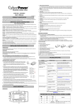
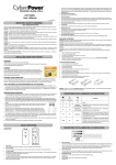
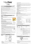
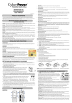
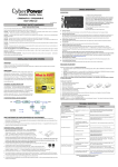
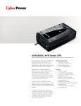
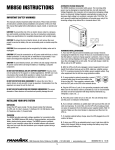
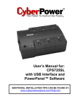
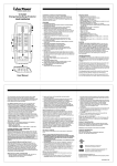
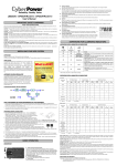
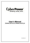
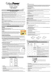
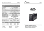
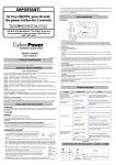
1.
Battery and Surge Protected Outlets
The unit has six battery powered and surge protected outlets to ensure temporary uninterrupted operation of your equipment during a power
failure. (DO NOT plug a laser printer, paper shredder, copier, space heater, vacuum cleaner, sump pump, or other large electrical
device into the “Battery and Surge Protected Outlets.” The power demands of these devices will overload and possibly damage
the unit.)
AVRG750LCD / AVRG900LCD
User’s Manual
2.
Full-Time Surge Protection Outlets
The unit has six surge suppression outlets.
K01-0000445-00
3.
Power Switch
Used as the master on/off switch for equipment connected to the battery power supplied outlets.
PRODUCT REGISTRATION
To turn the UPS ON, press the power button for approximately 2 seconds - you will hear a constant tone (1 second) - and release after a
short beep.
Thank you for purchasing a CyberPower product. Please take a few minutes to register your product at www.cpsww.com/registration.
To turn the UPS OFF, press the power button for approximately 2 seconds - you will hear a constant tone (1 second) - and release after two
Registration certifies your product's warranty, confirms your ownership in the event of a product loss or theft and entitles you to free technical
short beeps.
support. Register your product now to receive the benefits of CyberPower ownership.
Alarm setting: The audible alarm can be turned Off or On by quickly pressing the POWER button twice. The default setting is for the Alarm
IMPORTANT SAFETY INSTRUCTIONS
On. To turn the Alarm Off, quickly press the power button twice. You will hear two short beeps when the Alarm is turned Off. To turn the Alarm
back On, quickly press the power button twice. You will hear a single short beep when the Alarm is turned On. *When the Alarm is turned Off,
(SAVE THESE INSTRUCTIONS)
there will be no audible notification when the UPS reaches a low battery state.
This manual contains important safety instructions. Please read and follow all instructions carefully during installation and operation of the unit.
4.
Power On Indicator
This LED is illuminated when the utility power is normal and the UPS outlets are providing power, free of surges and spikes.
Read this manual thoroughly before attempting to unpack, install, or operate your UPS.
CAUTION! To prevent the risk of fire or electric shock, install in a temperature and humidity controlled indoor area free of conductive
contaminants.
5.
Mode Switch
Press the Mode Switch for approximately 3 seconds to enter setup mode to select three functions: Utility High Voltage Range, Utility Low
(Please see specifications for acceptable temperature and humidity range).
Voltage Range, and LCD sleep ON/OFF. When a function is selected, press Mode Switch for 3 seconds to view options. When an option is
CAUTION! To reduce the risk of electric shock, do not remove the cover except to service the battery. Turn off and unplug the unit before
selected, wait for 8 seconds for the setting to be confirmed. After the setting has been confirmed the LCD screen will leave setup mode and
servicing the batteries. There are no user serviceable parts inside except for the battery.
go back to status display. If there is no action for 8 seconds during setup, the LCD will also leave setup mode and go back to the status
CAUTION! Hazardous live parts inside can be energized by the battery even when the AC input power is disconnected.
CAUTION! The UPS must be connected to an AC power outlet with fuse or circuit breaker protection.
grounded.
display.
Do not plug into an outlet that is not
a. Utility High Voltage Range: Adjust the value of high voltage range.
If you need to de-energize this equipment, turn off and unplug the unit.
b. Utility Low Voltage Range: Adjust the value of low voltage range.
CAUTION! To avoid electric shock, turn off the unit and unplug it from the AC power source before installing a computer component.
c.
CAUTION! Not for use in a computer room as defined in the Standard for the Protection of Electronic Computer/Data Processing Equipment,
* When LCD is set to L1, LCD will be always ON. When LCD is set to L0, LCD will dim if untouched for 1 minute.
ANSI/NFPA 75.
* In battery mode, LCD is always on regardless if the setting is L1 or L0.
CAUTION! To reduce the risk of fire, connect only to a circuit provided with 20 amperes maximum branch circuit over current protection in
6.
LCD module display
LCD display shows all the UPS information using icons and messages. For more information please review the “Definitions for Illuminated
accordance with the National Electric Code, ANSI/NFPA 70.
LCD Indicators” section.
DO NOT USE FOR MEDICAL OR LIFE SUPPORT EQUIPMENT! CyberPower Systems does not sell products for life support or medical
applications.
LCD: L1/L0 (ON/OFF):
DO NOT use in any circumstance that would affect operation and safety of life support equipment, any medical applications or
7.
USB Port
The USB port allows connection and communication between the USB port on the computer and the UPS unit.
patient care.
DO NOT USE WITH OR NEAR AQUARIUMS! To reduce the risk of fire or electric shock, do not use with or near an aquarium.
Condensation
from the aquarium can cause the unit to short out.
8.
Communication Protection Ports
Communication protection ports will protect any standard modem, fax, or telephone line. (RJ11)
9.
Circuit Breaker
DO NOT USE THE UPS ON ANY TRANSPORTATION! To reduce the risk of fire or electric shock, do not use the unit on any transportation
such as airplanes or ships. The effect of shock or vibration caused during transit and the damp environment can cause the unit to short out.
INSTALLING YOUR UPS SYSTEM
Located on the side of the UPS, the circuit breaker provides overload and fault protection.
10. Ground Screw
The ground screw is used for any equipment that needs a chassis ground connection.
11. Outlets Designed for AC Adapters
The UPS unit has four widely-spaced outlets. AC power adapters can be plugged into the UPS without overlapping or blocking adjacent
INTRODUCTION
outlets.
Thank you for selecting a CyberPower Systems UPS product. This UPS is designed to provide unsurpassed power protection, operation and
REPLACING THE BATTERY
performance during the lifetime of the product.
Replacement of batteries located in an OPERATOR ACCESS AREA.
UNPACKING
1.
When replacing batteries, replace with the same number of the following battery: CyberPower / RB1270B for AVRG750LCD; CyberPower
/ RB1290A for AVRG900LCD.
(a) UPS unit (b) User’s manual (c) USB device cable
*PowerPanel® Personal Edition software is available on our website. Please visit www.cpsww.com and go to the Software Section
for a free download.
2.
CAUTION! Risk of Energy Hazard, 12V, maximum 9 Ampere-hour battery. Before replacing batteries, remove conductive jewelry such as
3.
CAUTION! Do not dispose of batteries in a fire. The batteries may explode.
AUTOMATIC VOLTAGE REGULATOR
4.
CAUTION! Do not open or mutilate batteries. Released material is harmful to the skin and eyes. It may be toxic.
Inspect the UPS upon receipt. The box should contain the following:
chains, wrist watches, and rings. High energy through conductive materials could cause severe burns.
The AVRG750 LCD / AVRG900LCD stabilizes inconsistent utility power to nominal levels that are safe
CAUTION - RISK OF EXPLOSION IF BATTERY IS REPLACED BY AN INCORRECT TYPE. DISPOSE OF USED BATTERIES ACCORDING
for equipment. Unstable utility power can be damaging to important data and hardware. With Automatic
TO LOCAL REGULATIONS.
Voltage Regulation (AVR), damaging voltage levels are corrected to safe levels.
TO REPLACE THE BATTERY
AVR automatically
increases low utility power to a consistent and safe 110/120 volts.
1.
Turn off and unplug all connected equipment.
HOW TO DETERMINE THE POWER REQUIREMENTS OF YOUR
EQUIPMENT
2.
Unplug it from the AC power source.
3.
Turn the UPS upside down.
1. Ensure that the equipment plugged into the UPS does not exceed the UPS unit’s rated capacity. If the rated capacities of the unit are
4.
Remove the 1 retaining screw.
5.
Slide the battery compartment cover completely off of the unit.
6.
Remove the battery from the compartment.
7.
Disconnect the battery wires from the battery.
HARDWARE INSTALLATION GUIDE
8.
Install the replacement battery by connecting the red wire and black wire to the positive (+) and negative (-) terminal of the battery.
1. Your new UPS may be used immediately upon receipt. However, after receiving a new UPS, to
9.
Put the battery back into the compartment.
exceeded, an overload condition may occur and cause the UPS unit to shut down or the circuit breaker to trip.
2. There are many factors that can affect the amount of power that your electronic equipment will require. For optimal system performance
keep the load below 80% of the unit’s rated capacity.
ensure the battery’s maximum charge capacity, it is recommended that you charge the battery
10. Slide back the battery compartment cover and tighten the retaining screw.
for at least 8 hours. Your UPS is equipped with an auto-charge feature. When the UPS is
11. Charge the unit for 8 hours to fully charge the battery.
plugged into an AC outlet, the battery will automatically charge whether the UPS is turned on or
REMINDER:
turned off.
collects used batteries for recycling, as required by local regulations.
Batteries are considered HAZARDOUS WASTE and must be disposed of properly.
2. With the UPS unit turned off and unplugged, connect your computer, monitor, and any other peripherals
TROUBLESHOOTING
requiring battery backup into the battery power supplied outlets. Plug the other peripheral equipment (eg.
printer, scanner, speakers, etc.) into the full-time surge protection outlets.
Most retailers that sell lead-acid batteries
DO NOT plug a laser printer,
paper shredder, copier, space heater, vacuum cleaner, sump pump, or other large electrical device into
the “Battery and Surge Protected Outlets”. The power demands of these devices will overload and
possibly damage the unit.
3. To protect a fax, phone, or modem line, connect a telephone cable from the wall jack outlet to the IN jack of the
UPS. Connect a telephone cable from one of the UPS OUT jacks to the modem port on the computer. The
Problem
Possible Cause
Full-time surge protection outlets
stop providing power to
equipment. Circuit breaker
button is projecting from the side
of the unit.
Solution
Circuit breaker has been tripped due
to an overload.
Turn the UPS off and unplug at least one piece of
equipment. Wait 10 seconds, reset the circuit breaker by
pressing the button, and then turn the UPS on.
Battery not fully charged.
Recharge the battery by leaving the UPS plugged in.
Battery is worn out.
Contact CyberPower Systems about replacement batteries
at [email protected].
The on/off switch is designed to
prevent damage from rapidly turning
it off and on.
Turn the UPS off. Wait 10 seconds and then turn the UPS
on.
The unit is not connected to an AC
outlet.
The unit must be connected to a 120V 60Hz outlet.
The battery is worn out.
Contact CyberPower Systems about replacement batteries
at [email protected].
Mechanical problem.
Contact CyberPower Systems at [email protected].
The frequency is outside of the
operating range of 57-63Hz.
Turn the UPS off. Make sure the frequency range is within
57-63Hz. Or you can turn the UPS on in battery mode.
The USB cable is not connected.
Connect the USB cable to the UPS unit and an open USB
port on the back of the computer.
The USB cable is connected to a
bad USB port.
Check for a different USB port and plug the cable in.
The unit is not providing battery
power.
Shutdown your computer and turn the UPS off. Wait 10
seconds and turn the UPS back on. This should reset the
unit.
other UPS OUT jack can be used to protect a telephone or fax machine.
4. Plug the UPS into a 2 pole, 3 wire grounded receptacle (wall outlet). Make sure the wall branch outlet is
protected by a fuse or circuit breaker and does not service equipment with large electrical demands (e.g. air
conditioner, refrigerator, copier, etc.). The warranty prohibits the use of extension cords, outlet strips,
The UPS does not perform
expected runtime.
and surge strips in conjunction with the UPS unit.
5. Press the power switch to turn the unit on. The Power On indicator light will illuminate green and the unit will “beep” once.
6. If an overload is detected, an audible alarm will sound and the unit will emit one long beep. To correct this, turn the UPS off and unplug at
least one piece of equipment from the battery power supplied outlets.
Make sure the circuit breaker is depressed and then turn the UPS on.
7. To maintain optimal battery charge, leave the UPS plugged into an AC outlet at all times.
8. To store the UPS for an extended period of time, cover it and store with the battery fully charged. While in storage, recharge the battery every
three months to ensure optimal battery life.
9. Ensure the wall outlet and UPS are located near the equipment being attached for proper accessibility.
BASIC OPERATION
The UPS will not turn on.
DESCRIPTION
PowerPanel® Personal Edition is
inactive (all icons are gray).
Additional troubleshooting information can be found at “Support” at www.CPSww.com
AVRG750LCD / AVRG900LCD
DEFINITIONS FOR LED INDICATORS & AUDIBLE ALARMS
Limited Warranty and Connected Equipment Guarantee
Read the following terms and conditions carefully before using the CyberPower AVRG750LCD/ AVRG900LCD (the “Product”). By
CONDITION
Power
Alarm
On
Off
using the Product you consent to be bound by and become a party to the terms and conditions of this Limited Warranty and
Connected Equipment Guarantee (together referred to as this “Warranty”). If you do not agree to the terms and conditions of this
Warranty, you should return the Product for a full refund prior to using it.
Normal
Who is Providing this Warranty?
Beep twice
On
every 30 seconds
Rapid beeping every 1/2
On
second
Utility Failure- The UPS is providing power to battery power-supplied outlets
CyberPower Systems (USA), Inc. (“CyberPower”) provides this Limited Warranty.
from its battery.
What Does This Warranty Cover?
Utility Failure- The UPS is providing battery power.
Rapid beeping indicates
This warranty covers defects in materials and workmanship in the Product under normal use and conditions. It also covers equipment
that was connected to the Product and damaged because of the failure of the Product.
the unit will run out of power soon.
What is the Period of Coverage?
Battery Mode or AC/Utility Power Mode Overload Fault- Occurs when
On/Off
Constant tone
This warranty covers the Product for three years. Connected equipment is covered for as long as you own the Product.
connected equipment exceeds the rating of battery outlets of the unit. Please
unplug at least one piece of equipment from battery outlets.
Who Is Covered?
This warranty only covers the original purchaser. Coverage ends if you sell or otherwise transfer the Product.
Off
Constant tone
Battery Output Short Fault- Please unplug at least one piece of equipment from
How Do You Get Warranty Service?
battery outlets and turn on the UPS again. If the fault still exists, please contact
1. Before contacting CyberPower, identify Your Product model number, the Purchase Date, and each item of Connected Equipment.
CyberPower Systems for support.
2. Email us at [email protected] or Call us at (877) 297-6937.
3. If your product requires warranty service you must provide a copy of your dated purchase receipt or invoice.
On
Constant tone
How Do You Open A Connected Equipment Claim?
Charger Fault- Contact CyberPower Systems for support.
1. Call us at (877) 297-6937 or write to us at Cyber Power Systems (USA), Inc., 4241 12th Ave. E., STE 400, Shakopee, MN 55379, or
send us an e-mail message at [email protected] for instructions, within 10 days of the occurrence.
2. When you contact CyberPower, identify the Product, the Purchase Date, and the item(s) of Connected Equipment. Have
DEFINITIONS FOR ILLUMINATED LCD INDICATORS
information on all applicable insurance or other resources of recovery/payment that are available to the Initial Customer and Request
a Claim Number.
INPUT voltage meter: This meter measures the AC voltage that the UPS system is receiving from the
3. You must provide a dated purchase receipt (or other proof of the original purchase) and provide a description of the damage to your
utility wall outlet. The UPS is designed to continuously supply connected equipment with stable output
connected equipment.
voltage. In the event of a complete power loss, severe brownout, or over-voltage, the UPS relies on its
4. Pack and ship the product to CyberPower and, if requested, the item(s) of Connected Equipment, a repair cost estimate for the
internal battery to supply consistent 110/120 output voltage. The INPUT voltage meter can be used as
a diagnostic tool to identify poor-quality input power.
The LCD display indicates a variety
of UPS operational conditions. All
descriptions apply when the UPS is
OUTPUT voltage meter: This meter measures, in real time, the AC voltage that the UPS system is
providing to the computer during normal AC/Utility Power mode, and battery backup mode.
plugged into an AC outlet and turned
on or when the UPS is on battery.
ESTIMATED RUNTIME: This displays the run time estimate of the UPS with the current battery
capacity and load.
damage to the Connected Equipment, and all claim forms that CyberPower provides to you. Show the Claim Number on the shipping
label or include it with the product. You must prepay all shipping costs, you are responsible for packaging and shipment, and
you must pay the cost of the repair estimate.
How Long Do I Have To Make A Claim?
All claims must be made within ten days of the occurrence.
NORMAL icon: This icon appears when the UPS is working under normal conditions.
What Will We Do To Correct Problems?
BATTERY icon: During a severe brownout or blackout, this icon appears and an alarm sounds (two short beeps followed by a pause) to indicate
CyberPower will inspect and examine the Product.
the UPS is operating from its internal batteries. During a prolonged brownout or blackout, the alarm will sound continuously to indicate the UPS’s
If the Product is defective in material or workmanship, CyberPower will repair or replace it at CyberPower's expense, or, if
batteries are nearly out of power. You should save files and turn off your equipment immediately or allow the software to shut the system down.
CyberPower is unable to or decides not to repair or replace the Product (if defective) within a reasonable time, CyberPower will refund
SILENT MODE icon: This icon appears whenever the UPS is in silent mode.
to you the full purchase price you paid for the Product (purchase receipt showing price paid is required).
OVER LOAD icon: This icon appears and an alarm sounds to indicate the battery-supplied outlets are overloaded. To clear the overload, unplug
If it appears that our Product failed to protect any equipment plugged into it, we will also send you forms for making your claim for the
some of your equipment from the battery-supplied outlets until the icon turns off and the alarm stops.
connected equipment. We will repair or replace the equipment that was damaged because of the failure of our Product or pay you the
BATT. CAPACITY meter: This meter displays the approximate charge level of the UPS's internal battery in 25% increments. During a blackout
fair market value (NOT REPLACEMENT COST) of the equipment at of the time of the damage. We will use Orion Blue Book, or
or severe brownout, the UPS switches to battery power (the BATTERY icon appears) and the battery charge level decreases.
another a third-party valuation guide, or eBay, craigslist, or other source to establish that amount. Our maximum liability is limited to
LOAD CAPACITY meter: This meter displays the approximate output load level of the UPS battery outlets in 25% increments.
$150,000 for the AVRG750LCD and $200,000 for the AVRG900LCD.
FAULT: The following number appears if there is a problem with the UPS. Press the POWER button to turn the UPS off.
E22: Battery Mode or AC/Utility Power Mode Overload fault (Unplug at least one piece of equipment from battery outlets and turn the
Who Pays For Shipping?
We pay when we send items to you; you pay when you send items to us.
UPS on again.)
E21: Battery Output Short fault (Unplug at least one piece of equipment from battery outlets and turn the UPS on again.)
What Are Some Examples Of What This Warranty Does Not Cover?
E01: Charger Fault (Contact CyberPower Systems for support)
1. This Warranty does not cover any software that was damaged or needs to be replaced due to the failure of the Product or any data
E24: Internal Fault (Contact CyberPower Systems for support)
that is lost as a result of the failure or the restoration of data or records, or the reinstallation of software.
2. This Warranty does not cover or apply to: misuse, modification, operation or storage outside environmental limits of the Product or
TECHNICAL SPECIFICATIONS
the equipment connected to it, nor for damage while in transit or in storage, nor if there has been improper operation or maintenance,
or use with items not designed or intended for use with the Product, such as laser printers, appliances, aquariums, medical or life
Model
AVRG750LCD
AVRG900LCD
Capacity
750VA / 450W
900VA / 480W
support devices, etc.
What Other Limitations Apply?
Nominal Input Voltage
120Vac
Input Frequency
60 Hz ± 3 Hz
On-Battery Output Voltage
120Vac ± 5%
Automatic Voltage Regulator (AVR)
Yes
On-Battery Output Frequency
60Hz ± 1%
1. This Warranty does not apply unless the Product and the equipment that was connected to it were connected to properly wired and
grounded outlets (including compliance with electrical and safety codes of the most current electrical code), without the use of any
adapters or other connectors.
2. The Product must have been plugged directly into the power source and the equipment connected to the Product must be directly
connected to the Product and not “daisy-chained” together in serial fashion with any extension cords, another Product or device
similar to the Product, surge suppressor, or power tap. Any such installation voids the Limited Warranty.
3. The Product and equipment connected to it must have been used properly in a suitable and proper environment and in
conformance with any license, instruction manual, or warnings provided with the Product and the equipment connected to it.
Max. Load for UPS Outlets
750VA / 450W
4. The Product must have been used at all times within the limitations on the Product’s VA/Watt capacity.
900VA / 480W
5. The sole and exclusive remedies of the Initial Customer are those provided by this Warranty.
What Limitations Apply if there is Connected Equipment Guarantee (CEG) Coverage for My Product?
Max. Load for Full-Time Surge Protection outlets
12 Amps
On-Battery Output Wave Form
Simulated Sine Wave Form
Operating Temperature
+ 32°F to 104° F / 0° C to 40° C
Operating Relative Humidity
0 to 90% NON-CONDENSING
Size (W x H x D)
12.2" x 7" x 3.5"
The Product was designed to eliminate disrupting and damaging effects of momentary (less than 1ms) voltage spikes or impulses
from lightning or other power transients. If it can be shown that a voltage spike lasting longer than 1ms has occurred, the occurrence
will be deemed outside the rated capabilities of the Product and the Limited Warranty is void. CyberPower Does Not Cover or
Undertake Any Liability in Any Event for Any of the Following:
1. Loss of or damage to data, records, or software or the restoration of data or records, or the reinstallation of software.
2. Damage from causes other than AC Power Line Transients, spikes, or surges on properly installed, grounded and code-compliant
120 volt power lines in the United States and Canada; transients, surges or spikes on standard telephone land lines, PBX telephone
equipment lines or Base 10T Ethernet lines, when properly installed and connected. (This exclusion applies, for example, to
Net Weight
14.0 lbs
14.3 lbs
Typical Battery Recharge Time
8 hours
Typical Battery Life
3 to 6 years, depending on number of discharge/recharge cycles
Recommended Battery
Sealed Maintenance Free Lead Acid Battery
Safety Approvals
UL1778(UPS), cUL107., FCC/DoC Class B
fluctuations in data transmission or reception, by CATV or RF transmission or fluctuations, or by transients in such transmission.)
3. Damage from any circumstance described as excluded above with respect to the Product.
4. Damages from fire, flood, wind, rain, rising water, leakage or breakage of plumbing, abuse, misuse or alteration of either the
product or the Connected Equipment.
5. CyberPower excludes any liability for personal injury under the Limited Warranty and Connected Equipment Guarantee.
CyberPower excludes any liability for direct, indirect, special, incidental or consequential damages, whether for damage to or loss of
Input
EMI
Filter
property [EXCEPT FOR (AND ONLY FOR) the specific limited agreement of CyberPower to provide certain warranty benefits
regarding "Connected Equipment" under this Warranty], loss of profits, business interruption, or loss of information or data. NOTE:
SYSTEM FUNCTION BLOCK DIAGRAM
Some States or Provinces do not allow the exclusion or limitation of incidental or consequential damages, so the above limitation may
Surge
Suppressor
AVR
Output
not apply to you.
6. The Product is not for use in high-risk activities or with aquariums. The Product is not designed or intended for use in hazardous
environments requiring fail-safe performance, or for use in any circumstance in which the failure of the Product could lead directly to
Charger
AC/DC
Inverter
death, personal injury, or severe physical or property damage, or that would affect operation or safety of any medical or life support
device (collectively, "High Risk Activities"). CyberPower expressly disclaims any express or implied warranty of fitness for High Risk
Normal Mode
Battery Mode
Battery
DC/A
C
CYBERPOWER GREENPOWER UPS™ TECHNOLOGY
Activities or with aquariums. CyberPower does not authorize use of any Product in any High Risk Activities or with Aquariums. ANY
SUCH USE IS IMPROPER AND IS A MISUSE OF THE PRODUCT.
Where Can I Get More Information?
The application of the United Nations Convention of Contracts for the International Sale of Goods is expressly excluded.
CyberPower is the warrantor under this Limited Warranty.
Advanced Energy-Saving Patented Bypass Technology
For further information please feel free to contact CyberPower at CyberPower Systems (USA), Inc. 4241 12th Ave E., STE 400,
CyberPower’s patented GreenPower UPS™ with Bypass Technology reduces UPS energy costs by up to
Shakopee, MN 55379; call us at (877) 297-6937; or send us an e-mail message at [email protected].
75% compared to conventional UPS models. Even when utility power is normal, conventional UPS models
constantly pass power through a transformer. By contrast, under normal conditions the advanced circuitry
of a GreenPower UPS™ bypasses the transformer. As a result, the power efficiency is significantly
CyberPower Systems encourages environmentally sound methods for disposal and recycling of its UPS products.
Please dispose and/or recycle your UPS and batteries in accordance to the local regulations of your state.
increased while decreasing waste heat, using less energy, and reducing energy costs.
When an abnormal power condition occurs, the GreenPower UPS™ automatically runs power through its
transformer to regulate voltage and provide “safe” power. Since utility power is normal over 88% of the time,
the GreenPower UPS™ operates primarily in its efficient bypass mode.
The GreenPower UPS™ is also manufactured in accordance with the Restriction on Hazardous Substances (RoHS) directive making
it one of the most environmentally-friendly on the market today.
All rights reserved. Reproduction without permission is prohibited.