1
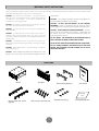
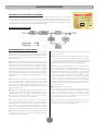
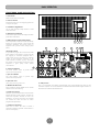
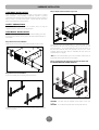
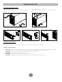
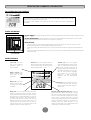
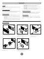
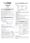
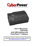
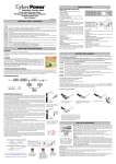
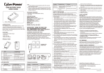
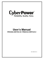
User’s Manual
PR5000LCDRTXL5U/ PR6000LCDRTXL5U
K01-0000124-04
IMPORTANT SAFETY INSTRUCTIONS
This manual contains important instructions. Please read and follow all instructions carefully during installation and operation of the unit. Read this manual
thoroughly before attempting to unpack, install, or operate the UPS.
exceed 3.5mA.
CAUTION! The UPS must be connected to a grounded AC power
outlet with fuse or circuit breaker protection. DO NOT plug the UPS into
an outlet that is not grounded. If you need to power-drain this
equipment, turn off and unplug the unit.
CAUTION! Do not unplug the unit from AC Power during operation, as
this will invalidate the protective ground insulation.
CAUTION! DO NOT USE FOR MEDICAL OR LIFE SUPPORT
EQUIPMENT! Under no circumstances this unit should be used for
medical applications involving life support equipment and/or patient care.
CAUTION! The battery can power hazardous components inside the
unit, even when the AC input power is disconnected.
CAUTION! The UPS should be near the connected equipment and
easily accessible.
CAUTION! DO NOT USE WITH OR NEAR AQUARIUMS! To reduce
the risk of fire, do not use with or near aquariums. Condensation from
the aquarium can come in contact with metal electrical contacts and
cause the machine to short out.
CAUTION! To prevent the risk of fire or electric shock, install in a
temperature and humidity controlled indoor area, free of conductive
contaminants. (Please see specifications for acceptable temperature and
humidity range).
DO NOT INSTALL THE UPS WHERE IT WOULD BE EXPOSED TO
DIRECT SUNLIGHT OR NEAR A STRONG HEAT SOURCE!
CAUTION! To avoid electrical shock, turn off the unit and unplug it from
the AC power source before servicing the battery or installing a computer
component.
DO NOT BLOCK VENTILATION OPENINGS AROUND THE HOUSING!
DO NOT CONNECT DOMESTIC APPLIANCES SUCH AS HAIR HAIR
DRYERS, SPACE HEATERS, VACUUM CLEANER ETC TO THE TO
UPS OUTPUT SOCKETS.
CAUTION! Never install a UPS, or associated wiring or equipment,
during a lightning storm.
CAUTION! When installing the equipment, ensure that the sum of the
leakage current of the UPS and the connected equipment does not
UNPACKING
UPS unit
Front panel
Rack mount ears (Stands) (2)
User’s manual
Warranty
Card
Rack mount rails (1 set – left and
right sides)
Rack mount ear & rails screws (34)
1
Screw hole dust covers (8)
Warranty registration card
INSTALLING YOUR UPS SYSTEM
AUTOMATIC VOLTAGE REGULATOR(AVR)
The PR5000LCDRTXL5U/ PR6000LCDRTXL5U stabilizes damaging inconsistent utility power. The Automatic
Voltage Regulator automatically regulates low or high voltages to keep equipment working at safe AC power levels
(208/220/230/240V) without switching to battery. Your equipment operates normally when power problems, such
as, shout brownouts and blackouts. The unit’s powerful sealed lead-acid batteries will provide power during the
incoming voltage drops below 131V or increases above 268V. (Default)
SYSTEM BLOCK DIAGRAM
HARDWARE INSTALLATION GUIDE
1. Battery charge loss may occur during shipping and storage.
7. To maintain an optimal battery charge, leave the UPS plugged into
an AC outlet at all times.
Before using the UPS, it’s strongly recommended to charge batteries
for twelve (12) hours typically to ensure that the batteries’ maximum
charge capacity is met. To recharge the batteries, simply plug the
UPS into an AC outlet.
8. Before storing the UPS for an extended period of time, turn the
unit OFF. Then cover it and store it with the batteries fully charged.
Recharge the batteries every three months to ensure good battery
capacity and long battery life. Maintaining a good battery charge will
help prevent possible damage to the unit from battery leakage.
2. When using the included software, connect either the serial or the
USB cable between the computer and the corresponding port on the
UPS. Note: If the USB port is used, the serial port will be disabled.
They cannot be used simultaneously. The computer with the
PowerPanel® Business Edition Agent software connects to the USB
port or the Serial port on the UPS. It can control the operating
schedule, battery test, outlet, etc. and obtain information on the UPS
status. However, other computers with PowerPanel® Business Edition
Client software can only obtain UPS status information via a LAN
connection.
9. The unit has one Primary Serial Port (I), one Secondary Serial
Port (II), and one USB port, (paired with the Primary Serial Port), to
allow connection and communication between the unit and any
attached computers. The Primary Serial Port (I) as well as its paired
USB port allow for bi-directional communication among the UPS and
the primary connected computer running the PowerPanel® Business
Edition Agent software. The UPS can control the computer’s
shutdown in case of an emergency, and at the same time, the
computer can monitor the UPS and alter its various programmable
parameters. On the other hand, secondary Serial Port II, only allows
the UPS to initiate the connected computer’s graceful shutdown in
case of an emergency.
3. With the UPS off and unplugged, connect your computer, monitor,
and any externally powered data storage device (Hard drive, Tape
drive, etc.) into the outlets. DO NOT plug a laser printer, copier,
space heater, vacuum, paper shredder or other large electrical device
into the UPS. The power demands of these devices will overload and
possibly damage the unit.
10. EPO (Emergency Power Off) Port:
Use the provided gray cable to connect to a special EPO contact
switch. Follow the appropriate circuit diagram on page 4 to wire the
cable to your EPO configuration. The EPO remote switch is a switch
installed in an outside area, connected to the unit via an ordinary
RJ-11 phone line. In case of an emergency, it can be used to
immediately cut off power from the UPS unit.
4. To protect a fax, telephone, modem line or network cable, connect
the telephone or network cable from the wall jack outlet to the jack
marked “IN” of the UPS. Then, connect a telephone cable or network
cable from the jack marked “OUT” on the UPS to the modem,
computer, telephone, fax machine, or network device.
5. Press the power switch to turn the UPS on. The Power-On
11. To avoid electrical shock, before hardwiring the UPS (in/out
power cord), turn the unit OFF and disconnect the unit from utility
power. The in/out power cord MUST be grounded.
indicator light will illuminate. If an overload is detected, an audible
alarm will sound and the UPS will emit one long beep. In order to
reset it, turn the unit off and unplug some equipment from outlets.
Make sure your equipment carry a load current within the unit’s safe
range, (refer to the technical specifications), and then turn the unit on.
6. Your UPS is equipped with an auto-charge feature. When the UPS
is plugged into an AC outlet, the battery will automatically charge,
even when the unit is switched off.
2
BASIC OPERATION
FRONT/REAR PANEL DESCRIPTION
1. Power Switch
Master On/Off switch for the UPS.
2. Power on Indicator
Indicates the UPS is on and supplying power free
of surges and spikes.
3. LCD Readout Toggle Button
Use to rotate through multiple screens of UPS
status information.
4. Multifunction LCD Readout
An illuminated digital screen that displays the UPS
power status information.
5. Battery Backup & Surge Protected Outlets
This unit provides a total of five outlets with battery
backup and surge protection. They ensure that
connected equipment will provide power to
equipment over a period of time, during a power
failure.
4
Critical /Non-Ccritical
It is possible to program the unit so that the outlet
block marked as “Non-Critical”, (3 ports), will stop
the supplying to connected equipment after a
certain period of time. This allows for additional
runtime for the equipment connected on the
outlets marked as “Critical”, (2 port). This allows
the creation of load priorities ensuring the critical
equipment is given priority under specific
circumstances.
240V, 20A
7
240 V ,20A
8
9
10 11 12
Expansion Port
6
3 2 1
5
6. Output Circuit Breaker
The circuit breaker serves to provide output
overload and fault protection.
7. Input Circuit Breaker
The circuit breaker serves to provide input
overload and fault protection.
8. Input Power Cord
Heavy-duty, extra long power cord.
9. SNMP/HTTP Network slot
Slot to install the optional SNMP card for remote
network control and monitoring.
10. Serial Port I (Primary)
Serial port I provides bi-directional communication
between the UPS and the computer. The UPS can
control the computer’s shutdown in case of an
emergency, and at the same time, the computer
can monitor the UPS and alter its various
programmable parameters.
12. USB port to PC
This is a connectivity port allowing communication and control between the UPS and the
connected computer. You should install the PowerPanel® Business Edition Agent software on
the PC/Server connected with the USB cord.
.
11. Serial Port II (Secondary)
Serial Port II allows the UPS to initiate a
connected computer’s graceful auto-shutdown in
case of an emergency.
3
BASIC OPERATION
240V , 20A
Expansion Port
13 14
240 V,20A
16
15
13. EPO (Emergency Power Off) Port*:
Allows for an emergency UPS Power-Off from a remote location.
14. Surge Protected Communication Ports - RJ11/RJ45
These ports are used to protect standard RJ-45/RJ-11 based, (ADSL, LAN,
Phone/Modem-Lines), and cabling systems from surges.
OPTION 1: USER SUPPLIED NORMALLY OPEN SWITCH
15. Extended Runtime (XL) Battery Pack Connector
Provides a connection for additional CyberPower XL Battery Packs:
BPL48V75ART2U.
(RECOMMENDED)
N.O.EPO SWITCH
4
3
RJ11
PLUG
2
1
16. Ground Stud
Use the Ground Stud to ground the UPS.
NO CONNECTION
OPTION 2: USER SUPPLIED NORMALLY CLOSED SWITCH
4
3-4 JUMPER
3
RJ11
PLUG
2
N.C.EPO SWITCH
1
NO CONNECTION
4
HARDWARE INSTALLATION
Step 3: Adjust rack mount rails to fit your rack
HARDWARE INSTALLATION
These versatile UPS systems can be mounted in a rack mount or vertical
/tower orientation. This versatility is especially important to growing
organizations with changing needs that value having the option to position a
UPS on a floor, or in a rack mount system. Please follow the instructions
below for the respective mounting method.
SAFETY PRECAUTIONS
CAUTION! To prevent the risk of fire or electric shock, use only the
supplied hardware to attach the mounting brackets.
RACKMOUNT INSTALLATION
*Note: Before the rack mount installation, the internal battery pack shall
be removed first. Please refer to page 9 BATTERY INSTALLATION for
more details.
Step 1: Rack mount ears installation
Attach the two rack mount ears to the UPS using the provided screws.
Take the rack mount rail inscribed with an “L” (Left) and attach it to the
rear bracket of the rack mount rail using three (3) of the six (6) rack
mount rail screws. Do not fully tighten the rack mount rail screws, as
the rack mount rails will need to be adjusted to fit your rack. Once
complete, perform the same steps for assembling the rack mount rail
inscribed with an “R” (Right).
*Note: Now the internal battery pack can be installed. Please refer to
page 9 BATTERY INSTALLATION for more details.
Step 4: Carefully align the front panel connector and latches with
the PR5000LCDRTXL5U/ PR6000LCDRTXL5U
Step 2: Rack mount rail Installation
Ensure rack stability prior to installing devices in the rack.
CAUTION! The UPS must be installed at the bottom of the rack
system.
CAUTION! Do not lift the front panel when removing the UPS unit.
Attach the rack mount rails to your rack using fasteners that are designed
for your rack system.
5
HARDWARE INSTALLATION
VERTICAZL/TOWER INSTALLATION
Step 1: Attach the base stands
Simply slide the base stands onto the bottom of the UPS, roughly 8-10”
apart.
Step 2: Attach dust covers
Insert dust covers into the rack mount ear screw holes that are not being
used.
Step 3: Rotate the Multifunction LCD Readout
Separate the front panel and the UPS. Gently lift the LCD out. Rotate it to the preferred orientation. Reinstall the display for a tower configuration.
ELECTRICAL INSTALLATION
After completing the hardware installation of the UPS, you are now ready to plug in the UPS and attach your equipment.
SAFETY PRECAUTIONS
•
CAUTION! - Installation environment should be in a temperature and humidity controlled indoor area free of conductive contaminants. Do not install
•
•
•
•
CAUTION! - Never install a UPS, or associated wiring or equipment, during a lightning storm.
CAUTION! - Do not work alone under hazardous conditions.
CAUTION! - To reduce the risk of electric shock, do not remove the top cover.
CAUTION! - The battery can energize hazardous live parts inside even when the AC input power is disconnected.
this UPS where excessive moisture or heat is present (Please see specifications for acceptable temperature and humidity range)
6
DEFINITION FRO ILLUMINATED LCD INDICATORS
MULTIFUNCTION LCD READOUT
The multifunction LCD readout provides ready access to power/battery condition vitals, such as:
Runtime, Load, Temperature, and much more.
The screen is also rotatable so the UPS can be used in either rack mount or vertical/tower
orientation.
BASIC OPERATION
Screen toggle – To toggle through the status screens press the Select button which is located directly next to the
LCD.
Screen illumination– After 30 seconds of inactivity, the LCD backlight will automatically turn off to conserve
energy. Keeping the LCD screen lit at all times is not an option on this UPS.
Select Button
•
•
•
If the LCD screen is not lit pressing the Select button once will turn the LCD on. If the LCD screen is lit, then
pressing the Select button once will toggle through the status screens.
Pressing and holding the Select button for four (4) seconds while UPS is in Normal operation will initiate the Self
Test.
Pressing and holding the Select button for four (4) seconds while UPS is in Battery/Offline mode will activate Silent
Mode on the UPS.
Select Button
MAIN FEATURES
Load Level: The total
load of the connected
equipment shown in
20% increments.
Silent icon: This icon appears when the
UPS is in silent mode. During Silent mode,
the unit’s alarm does not sound until the
Battery Capacity falls to < 20%.
Battery Capacity: The
battery’s current charge
level shown in 20%
increments.
Normal Icon: This icon
appears when the UPS
is working under normal
conditions.
Overload icon: This icon appears
when the Battery/Surge outlets on the
UPS are overloaded. The UPS will
also sound an alarm at this point. To
clear the overload, the total load of the
connected equipment must be less
than the unit’s maximum capability.
The easiest way to correct this
problem is to remove noncritical
equipment from the Battery/Surge
outlets.
Fault icon: This icon appears if there is
an internal problem with the UPS.
Please contact Technical Support if
this icon is lit.
Automatic Voltage Regulation (AVR) icon: This icon
appears when the UPS is automatically correcting
AC input line voltage without using battery power.
This is a normal, automatic operation of your UPS,
and no action is required. The AVR in this UPS
continuously conditions the power to a nominal 208V
output to connected equipment. In the event of a
complete power loss, severe brownout, or over
voltage, the UPS relies on its internal battery back
up to supply a consistent 208V output.
Battery Icon: This icon appears when the UPS is
operating using battery power. The UPS will also
sound alarms (two short beeps followed by a pause)
when this icon is lit. When the Battery Icon is lit and
the Battery Capacity falls to 20% the frequency of
the alarms will increase indicating that the UPS
batteries are nearly out of power. If this occurs, it is
recommended that you either restore AC power, or
manually power down your equipment that may be
negatively affected by sudden power loss.
7
DEFINITION FRO ILLUMINATED LCD INDICATORS
TOGGLE SCREENS
Input Voltage
Output Voltage
The Input Voltage screen displays the AC
voltage that the UPS system is receiving
from the utility wall receptacle. This can
be used as a diagnostic tool to identify
poor quality input power. Units are listed
in V (Volts).
The Output Voltage screen measures, the
AC voltage that the UPS is providing to
your connected equipment via the UPS
outlets. Units are listed in V (Volts).
Estimated Runtime
Output Frequency
The Estimated Runtime Screen displays
how many minutes of runtime can be
expected of the UPS if it were to
experience a power outage. Note: The
number displayed may be less than
actual runtimes for low loads.
The Output Frequency screen displays
the current frequency at which the UPS
is operating. Units are listed in Hz
(Hertz).
Load Capacity
Battery Capacity
Similar to the Load/Current Level screen,
this displays the total load/current of the
connected equipment expressed as a
percentage (%).
The Battery Capacity screen displays the
battery’s current charge level and is
expressed as a percentage (%) of the
battery’s total capacity of 100%.
Temperature
Temperature
The Temperature screen displays the
internal temperature of the UPS in
degrees Centigrade. Normal ranges are
0 -40 . If the temperature exceeds
40 , additional methods should be
implemented to cool the UPS (i.e. air
conditioning,
additional
ventilation,
isolation from other heat producing
equipment, etc.).
The Temperature screen displays the
internal temperature of the UPS in
degrees Fahrenheit. Normal ranges are
32 -104 . If the temperature exceeds
104 , additional methods should be
implemented to cool the UPS (i.e. air
conditioning,
additional
ventilation,
isolation from other heat producing
equipment, etc.)
℃ ℃
℃
℉ ℉
℉
Load
This displays the total load of the
connected equipment.
8
MAINTENANCE
Storage
•
To store your UPS for an extended period, cover it and store with the
battery fully charged. Recharge the battery every three months to ensure
battery life.
•
•
Battery Replacement
Please read and follow the Safety Instructions before servicing the
battery. Battery replacement should be performed by trained personnel
who are familiar with the procedures and safety precautions.
CAUTION! – Only use replacement batteries which are certified
•
by CyberPower Systems. Use of incorrect battery type is an
electrical hazard that could lead to explosion, fire, electrical shock,
or short circuit.
CAUTION! – Batteries contain an electrical charge that could
cause severe burns. Before servicing batteries, please remove
any conductive materials such as jewelry, chains, wrist watches,
and rings.
Electrolyte fluid is harmful to the skin/eyes and may be toxic.
CAUTION! – To avoid electrical shock, turn off and unplug the
UPS from the wall receptacle before servicing the battery.
CAUTION! – Only use tools with insulated handles. Do not lay
tools or metal parts on top of UPS or battery terminals.
Replacement Batteries
Please refer to the Technical Specifications of the user manual for the
model number of the correct replacement batteries. To purchase these
batteries, log onto www.CPSww.com, or contact your local dealer.
Safety Precautions
•
CAUTION! – Do not open or mutilate the batteries.
Battery Disposal
Batteries are considered hazardous waste and must be disposed of
properly. Contact your local government for more information about
proper disposal and recycling of batteries. Do not dispose of batteries
in a fire.
Battery Installation
1 Remove the front panel.
○
4 Put the new battery modules back into the
○
compartment.
2 Remove the retaining screws of the cable
○
3 Pull the plastic sticker out slowly to
○
protection cover, and then remove the cover
itself.
remove the battery module.
5 Tighten the screws and replace the cable
○
protection cover and the front panel.
9
TECHNICAL SPECIFICATIONS
Model
Configuration
Capacity (VA)
Capacity (Watts)
Energy-saving Technology
Input
Nominal Input Voltage*
Input Voltage Range*
Input Adjustable Voltage Range*
Frequency Range
Input Plug Type
Cold Start
Output
UPS Outlets
On Battery Output Voltage
On Battery Output Frequency
Transfer Time (Typically)
Overload Protection
Data line Protection
Surge Protection
Phone / Network Protection
Battery
Battery Model
Sealed, Maintenance Free
User Replaceable
Recharge Time (Typically)
Status Indicators
Indicator LEDs
Audible Alarms
Environment
Operating Temperature
Operating Relative Humidity
Management
On-Device Features
Connectivity Ports
SNMP/HTTP Capable
Software
Power Management Software
Physical
Dimensions (LxWxH)
Weight
Safety
Conformance Approvals
Warranty
Product Warranty
Connected Equipment Guarantee
PR5000LCDRTXL5U
PR6000LCDRTXL5U
5000VA
4000W
6000VA
4500W
GreenPower UPS™ Bypass
208/ 220/ 230/ 240V (Default: 208V)
148 – 254V (Default)
131 – 268V (Default)
50/60Hz +/- 3Hz
NEMA L6-30P
Yes
(3) NEMA L6-30R, (2) NEMA L6-20R
Pure Sinewave, 208/ 220/ 230/ 240V +/- 5%
50/60Hz +/- 0.1Hz
4ms
On Utility: Circuit Breaker; On Battery: Internal Current Limiting
2430J
2430J
RJ11/RJ45 (One In/One Out)
RB1290X16
Yes
Yes
6 hours 90%
Power On, LCD Display (Using Battery, AVR, Load Level, Battery Level)
On Battery, Low Battery, Overload
℉ to 104℉ ( 0℃ to 40℃)
32
0 to 95% Non-Condensing
Self Test, Auto-Charge, Auto-Restart
(1) USB, (2) Serial
Yes [with optional RMCARD 205]
PowerPanel® Business Edition
25.25 x 17 x 8.75 (in) / 640 x 430 x 222 (mm)
222 lbs / 101 kg
226 lbs / 103 kg
UL1778, cUL107, FCC Part 15 Class A, CSA
3 years Limited
400,000
*The Nominal Input Voltage and Input Adjustable Voltage Range can only be configured through software. Input Voltage Range and Input Adjustable
Voltage Range will change when Nominal Input Voltage setting is changed. UPS firmware version must be 4.27 or above. Pressing and holding the
LCD screen Select button for ten (10) seconds while UPS is in Normal operation will display the UPS firmware version.
10
TROUBLESHOOTING
Problem
Possible Cause
Circuit breaker has tripped due to an
overload.
Outlet does not provide
power to equipment.
Batteries are discharged
Unit has been damaged by a surge or
spike.
Uncritical outlets have turned off
automatically due to an overload.
Solution
Turn the UPS off and unplug at least one piece of equipment. Wait 10
seconds, reset the circuit breaker by depressing the button, and then
turn the UPS on.
Recharge the unit for at least 4 hours
Contact CyberPower Systems about replacement batteries at
[email protected].
Push the toggle button to make the uncritical outlets turn on.
The UPS does not perform
expected runtime.
Batteries are not fully charged.
Recharge the batteries by leaving the UPS plugged in.
Batteries are degraded.
Contact CyberPower Systems about replacement batteries at
[email protected].
The UPS will not turn on.
The on/off switch is designed to
prevent damage by rapidly turning it
off and on.
The unit is not connected to an AC
outlet.
PowerPanel® Business
Edition is inactive.
Turn the UPS off. Wait 10 seconds and then turn the UPS on.
The unit must be connected to a 220/230/240V outlet.
Batteries are worn out.
Contact CyberPower Systems about replacement batteries at
[email protected].
Mechanical problem.
Contact CyberPower Systems at [email protected].
The serial cable or USB cable is not
connected.
The cable is connected to the wrong
port.
The unit is not providing battery
power.
The serial cable is not the cable that
was provided with the unit.
Connect the cable to the UPS unit. You must use the cable that came
with the unit.
Try another port of your computer.
Shutdown your computer and turn the UPS off. Wait 10 seconds and
turn the UPS back on. This should reset the unit.
You must use the cable included with the unit for the software.
Additional troubleshooting information can be found at “Support” area of www.CPSww.com.
11
PRODUCT REGISTRATION & WARRANTY
If the Product is defective in material or workmanship, CyberPower will
repair or replace it at CyberPower's expense, or, if CyberPower is unable to
or decides not to repair or replace the Product (if defective) within a
reasonable time, CyberPower will refund to you the full purchase price you
paid for the Product (purchase receipt showing price paid is required).
Product Registration
CyberPower requests that you complete and return the Warranty
Registration Card enclosed with the Product or register the Product at its
website (www.CPSww.com) to establish that you are the Initial Customer
of the Product, and therefore entitled coverage under the Limited
Warranty and the Connected Equipment Guarantee. (Registration is not
required for coverage, but note: if you do not register your purchase, you
will be required to provide proof of purchase.)
If it appears that our Product failed to protect any equipment plugged into it,
we will also send you forms for making your claim for the connected
equipment. We will repair or replace the equipment that was damaged
because of the failure of our Product or pay you the fair market value (NOT
REPLACEMENT COST) of the equipment at of the time of the damage.
We will use Orion Blue Book, or another a third-party valuation guide, or
eBay, craigslist, or other source to establish that amount. Our liability is
limited to the Connected Equipment Guarantee amount as stated in the
Technical Specifications section.
Limited Warranty and Connected Equipment
Guarantee
Read the following terms and conditions carefully before using the
CyberPower UPS (the “Product”). By using the Product you consent to be
bound by and become a party to the terms and conditions of this Limited
Warranty and Connected Equipment Guarantee (together referred to as
this “Warranty”). If you do not agree to the terms and conditions of this
Warranty, you should return the Product for a full refund prior to using it.
Who Pays For Shipping?
We pay when we send items to you; you pay when you send items to us.
What Are Some Things This Warranty Does Not Cover?
This Warranty does not cover any software that was damaged or
needs to be replaced due to the failure of the Product or any data that
is lost as a result of the failure or the restoration of data or records, or
the reinstallation of software.
2. This Warranty does not cover or apply to: misuse, modification,
operation or storage outside environmental limits of the Product or the
equipment connected to it, nor for damage while in transit or in storage,
nor if there has been improper operation or maintenance, or use with
items not designed or intended for use with the Product, such as laser
printers, appliances, aquariums, medical or life support devices, etc.
1.
Who Is Providing This Warranty?
CyberPower Systems (USA), Inc. (“CyberPower”) provides this Limited
Warranty.
What Does This Warranty Cover?
This warranty covers defects in materials and workmanship in the
Product under normal use and conditions. It also covers equipment that
was connected to the Product and damaged because of the failure of the
Product.
.
What Is The Period of Coverage?
This warranty covers the Product for three years and connected
equipment for as long as you own the Product.
Who Is Covered?
This warranty only covers the original purchaser.
sell or otherwise transfer the Product.
What Are The Limitations?
1. This Warranty does not apply unless the Product and the equipment
that was connected to it were connected to properly wired and
grounded outlets (including compliance with electrical and safety codes
of the most current electrical code), without the use of any adapters or
other connectors.
2. The Product must have been plugged directly into the power source
and the equipment connected to the Product must be directly
connected to the Product and not “daisy-chained” together in serial
fashion with any extension cords, another Product or device similar to
the Product, surge suppressor, or power tap. Any such installation
voids the Limited Warranty.
3. The Product and equipment connected to it must have been used
properly in a suitable and proper environment and in conformance with
any license, instruction manual, or warnings provided with the Product
and the equipment connected to it.
4. The Product must have been used at all times within the limitations on
the Product’s VA capacity.
Coverage ends if you
How Do You Get Service?
1. Call us at (877) 297-6937 or write to us at Cyber Power Systems (USA),
Inc., 4241 12th Ave. E., STE 400, Shakopee, MN 55379 or send us an
e-mail message at [email protected] for instructions.
2. When you contact CyberPower, identify the Product, the Purchase
Date, and the item(s) of Connected Equipment. Have information on all
applicable insurance or other resources of recovery/payment that are
available to the Initial Customer and Request a Claim Number.
3. You must provide a purchase receipt (or other proof of the original
purchase) and provide a description of the defect.
4. Pack and ship the product to CyberPower and, if requested, the item(s)
of Connected Equipment, a repair cost estimate for the damage to the
Connected Equipment, and all claim forms that CyberPower provides
to you. Show the Claim Number on the shipping label or include it with
the product. You must prepay all shipping costs, you are
responsible for packaging and shipment, and you must pay the
cost of the repair estimate.
Where Can I Get More Information?
For further information please feel free to contact CyberPower at Cyber
Power Systems (USA), Inc. 4241 12th Ave E., STE 400, Shakopee, MN
55379; call us at (877) 297-6937; or send us an e-mail message at
[email protected].
Recycle Policy
CyberPower Systems encourages environmentally sound methods for
disposal and recycling of its UPS products.
How Long Do I Have To Make A Claim?
All claims must be made within ten days of the occurrence.
What Will We Do To Correct Problems?
CyberPower will inspect and examine the Product.
Please dispose and/or recycle your UPS and batteries in accordance to the
local regulations of your state.
12
SERVICE INFORMATION
FREQUENTLY ASKED QUESTIONS (FAQs)
What types of equipment are NOT allowed to be plugged into the UPS?
Any device which exceeds the unit’s VA/Watt rating should not be plugged into the UPS. High drain devices, medical equipment, and aquatic equipment
also void the unit’s warranty. Below is a list of other devices that also void the warranty.
•
Laser printers
•
Space heaters
•
Copiers
•
Paper shredders
•
Vacuums
•
Curling Irons
Can I increase the runtime by hooking up multiple UPS units in a row?
This configuration is called “daisy-chaining” and will void the UPS’s warranty.
Can I hookup a surge strip to the UPS unit?
No. Surge strips cannot be installed before or after the UPS unit. Doing so will void the UPS’s warranty. If you require additional outlets, upgrade your
UPS to a model that has more outlets, or simply add an additional UPS to your existing configuration. If you need a longer input cord, you can purchase a
UL certified extension cord that is rated for the respective current of the unit. This cord MUST be a single-outlet extension cord.
Should the cooling fan on my CyberPower UPS be running at all times?
No. The internal cooling fan will only run when it’s required. CyberPower UPS systems utilize an internal thermal sensor which activates the fan when the
temperature exceeds a certain threshold. When the UPS is running Online (off AC power), it is completely normal for the fan to not be running.
Do I have to have the UPS turned on in order for it to charge?
No. The UPS will charge the battery whether the unit is turned on or turned off.
My LCD screen shuts off after 15-30 seconds of inactivity. Is there a way to keep the LCD screen illuminated at all times?
No. The LCD display will only light up when the Select button is pressed. This extends the life of the LCD screen and is part of the energy saving design of our
UPS systems.
NEED ADDITIONAL HELP?
Contact the Tech Support department with installation, troubleshooting, or general product questions.
CyberPower Technical Support
Phone: 1-877-297-6937
Email: [email protected]
Web: www.CPSww.com
Mail: 4241 12th Avenue E, Suite 400 Shakopee, MN 55379
Hours of Operation:
Monday – Friday, 8:00am – 5:00pm (CST)
13
SAFETY COMPLIANCE STATEMENT
FCC Compliance Statement
This device complies with part 15 of the FCC rules. Operation is subject to the following two conditions: (1) this device may not cause harmful interference,
and (2) this device must accept any interference received, including interference that may cause undesired operation.
Note: This equipment has been tested and found to comply with the limits for a Class A digital device, pursuant to part 15 of the FCC Rules. These limits are
designed to provide reasonable protection against harmful interference when the equipment is operated in a commercial environment. This equipment
generates, uses, and can radiate radio frequency energy and, if not installed and used in accordance with the instruction manual, may cause harmful
interference to radio communications. Operation of this equipment in a residential area is likely to cause harmful interference in which case the user will be
required to correct the interference at his own expense.
Important: Changes or modifications not expressly approved by the party responsible for compliance could void the user's authority to operate the
equipment.
Canadian Compliance Statement
This device complies with Industry Canada licence-exempt RSS standard(s). Operation is subject to the following two conditions: (1) this device may not
cause interference, and (2) this device must accept any interference, including interference that may cause undesired operation of the device.
Le présent appareil est conforme aux CNR d'Industrie Canada applicables aux appareils radio exempts de licence. L'exploitation est autorisée aux deux
conditions suivantes : (1) l'appareil ne doit pas produire de brouillage, et (2) l'appareil doit accepter tout brouillage radioélectrique subi, même si le brouillage
est susceptible d'en compromettre le fonctionnement.
CAN ICES-3 (A)/NMB-3(A)
14