1
No.1877
ADVANCED
SIGNAL PROCESSED
PASSIVE INFRARED
MOTION DETECTOR
I
MARGIN
LINES INDICATE
PRINCIPAL
GENERAL INFORMATION:
I
The NO. 1877 PIR provldas 12 zones of wide-angle coverage with a range
Of up t0 40 ht. 0111 ZQYS Or lynow Coverage with a range of up to 70
leet and has the foltowmg w
lealures
l Ouad element pyroeCcn~C w
POvtdtng the reltability of two
covermg the same area.
completely separate oua~l High preason. com~cr
avqva
oarabokc optical system
0 Low current drain wn0 a&1(111Iof cxlenoeci system power source
battery Me.
l Preset zones for tast ti
l as1 muauatlon
l Wall/comer mounting maw
l Dual channel sgnal vwtiw
1~ rtducea talse alarms
0 Pulse Count Capabhcr KY Lllruqeo False Alarm lmmunlty
0 6V lo 12V.X operrlor
The No. 1877 must w po&rr: hi”. a fnerea 6V.DC to 12V.DC source
Ihat can prowOe al Ieasr 4 ~PJI (rr wnooy power The No. 495 Power
Supply which can be 01~
wt%
nto any 24 hour 1POV.ACoullel can
b& used as a convenleol bcu:c Q 6ti DC navtng up to 12 hours standby
The detector IS deS@gWO IO maw
•~ att tomes The LED on the unll will
light whenever mobon IS dmtlec
PRINCIPLES OF OPERATION:
The optical system atwoes mr area mlo a seros of pmecled zones A
quad element sensor meawes lne level 01 uWrare0energy In each zone
When an Intruder crosses u cnlers any zone an alarm condlrlon rnll be
reported
The detector IS conllgureo *nth a quad etemeru sensor and two
independent stgnal processmg l mpl~llers In @ccl two passrve Infrared
sensors are shanng a common optcal system Bm sensors must detect
motion al the same time (or me PIR to repon on l ymr In thus way
immunity is provtded agamnsrtalse alarms anrQute0 lo channel nose and
random detector dlslurbances wht~e catcn pMomunce IS not
compromised.
.-*
COVERAGE CONSIDERATIONS
LAYOUTS:
AND TYPICAL
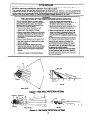
The range will depeno upon the mnror sfircm m use Proteclwe pallems
are shown tn Diagrams 1 and 2 However me rcH mar De mounle0 al
other heights with modlhed range coveragc as porn n Diagram 3
“Dead Zone” Caulton Nme m Diagram 1 ma! a 0ea0 zone” IS m~~calecl
withm whtch a person could be moving ano nU DCoetected by any of tne
unit’s protective zones Olher 0eao zones mop occu between the Oeleclm
and the downward ftelos of vtew as the UM s ~
MlghI n nCree¶M
As shipped !rom Aoemco. PIR coverage IS Wr m rot angle Snarler
range. TO CHANGE TO LONG RANGE PROTECTION. 10lbw MC
mirror change tnstruCtrOnSpaCke0 With the m mv mirror
Selecting a Mounting Location:
The No. 1877 Passive lntrared Detector resprnOs to changes In energy
which occur when an lntruoer moves into 01 OUIc# a pOleCllve zone Best
coverage will be obtained if the mounting Me 6 amecled such lhal IM!
likely direclion 01 intruder motion IS ACROSS mC mnam
Passive IF. unlls are remarkably resistant lo tatse Uam, hazards. but tth?
followmg recommendations should be ot%efveO
Avold locating unll where central healmg rao&alors. llames. or healmg
outlet ducts are wIthin the proteclive zones
Avoid locating the unil in direct sunllgnl or 01M!Ctlyabove Strong
sources of heal.
Avoid locating unit on unstable Surtaces
Avoid running alarm winng close lo heavy Ouly electricat cables.
INSTALLATION
AND WIRING:
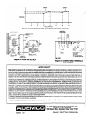
Mounting:
@
I. Mount the *nit plate to a tirm rsr(ksl surtti
(flat on watt of
in corner). as shown in Diagram 4. at the recommended height
CHANGES
IN THIS l/87
I
ISSUE
(see previous sectton). Onent Ihe plate so that the rectangular
cutout in the plate is at the botlom. If wiring IS provided from a
hole in the mounting surtace. locale the mounlmg plate so lhal
the wiring hole IS centered horuontaliy wlthm the rectangular
culou! in the plate and the bottom edge 01 the plate is poslloned
in-line with the center of the wiring hole. See Diagram 4. Detail A
Thus will align the wiring hole with the wmng entry In the case
when the unit is secured.
Wiring holes should be no larger than 5116” In dtameler.
2 Remove the tront cover irom the detector.
3. Using the wire entry access et the lower rear of the case,
carefully feed the wires through the foam comb in the entry and
along the underslde of the terminal block. Wire length should be
adequate for connection to the PIR terminal block. but
unnecessary splices and loops within the unit are lo be avoided.
Theloam se81 should surround the wires end block dmfIs
from entering the PIR enclosure.
4. Attach the unit to lhe wall plate as follows: Engage all lour
hooks on the wall plate into the slots on the rear ot the case (see
Diagram 4) and secure the unit to the wall plate by pressing
downward.
NO=
Wilh tront cover secured in ptace. unit is locked lo wall mounting
plate To detach unit from wall plate. Iron1 cover must be removed
lirst
Wiring Connections:
See Diagram 5 for connections. which should be made in this order:
1. Alarm Relay: To connect to a closed circuit protecbve loop see
diagram.
2. Input 6V112V.DC (+) and (-) Terminals: Connect these termmals
to a 6V.DC to 12V.DC source that can provrde 35 mA contnuously. Note: Observe polarity! 6V.DC can ba conveniently provided directly from any 24 hour 12OV.DC outlet via a No. 495
Power Supply which plugs directly into the outlet.
OPTIONAL OPERATING MODES:
As shipped. each detector includes pulse count circuitry that provides
stability In adverse envtronments to minimize false alarms. In this mode.
the No 1877 will normally signal an alarm within 3 to 4 steps, since the
POceSsng logic requires more complex motion than just a momentary
event The LED. however, functtons as a walk test indicator operatmg
moependently 01 the processing circuit
tnstent Response Option:
For bongmnge l ppllutionr where the detector is used to protect
nwrow conidors, or whore single pro&We hones we directed
through doorways or room openings, the Instsnt Response Optlon
mu81 be used.
This OPtIOnIS programmed by cutting the BLUE jumper on the circuit
board. See Diagram 5 for its location. Control slgnal voltage IS not
required. Use of this option will bypass the unit’s pulse count I~IC and
provide an instant alarm response when an intruder enters any single
protective zone.
CAUTION: Any )umper that is cut must have Its loose ends teped (or
otherwise insulated) to prevent l ccidentel contact with
other points.
I
tntruston Memory Option:
When used with a control that can provide a s&able switched voltage to
the detector’s control slgnal post (lo slgnal whether the control IS ARMED
or DISARMED). the detector can be programmed by cutting the RED
jumper (See Diagram 5 for 11slocation) to provide intrusion memory as
described in this section. NOTE: A push-on connector IS provided for use
on the CONTROL SIGNAL POST.
CAUTION: Before cuttmg the RED jumper. make sure thal the control can
prowde the proper swdched voltage signal lo the + CONTROL SIGNAL
terminal. as follows: System Armed: OV. System Disarmed: 6-12V. (input
I
I
impedance: 400K ohms). Many Ademco control panels are sources of
switched positive (+) control voltage signals. Some controls permit direct
Connection to the detector while others require the use of a No. 666/66612 OPenlng/Closing Switching Module between the control and the
detector. Consult your control panel tnstructions.
Tmuhb 2: UNIT GOES INTO ALARM INTERMlmNTLY
OR CONTINUOUSLY FOR NO APPARENT REASON AND WALKTEST LIGHT DOES NOT COME ON WHEN ALARM CDNDlTtON EXISTS.
During the ARMED period. if an intrusion occurs tn the protected area, the
alarm relay will transfer and this tact will be stored in the detector’s
memory. When the system IS subsequently disarmed. the LED will remain
illuminated until cleared. The LED memory can he cl-red by
mOfhentMly ARMING and then DISARMING the system. The LED will
then respond ON and OFF normally to motion detected in the protected
area dunng the DISARMED period,
CAUSE
A DC voltage rupply to
detwztor trom panel or power
Urppty inadequate or l h8ent.
PROPER POLARITY MUST
BE OBSERVED.
TESTING:
IMPORTANT: Wait at least two minutes atter applying power before
attempting to walk-test unit.
Testing of the detector should be conducted with the protected area
cleared of all people. In some business establishments. it may be more
convenient to do this after the business is closed. The protectwe system’s
control should be disarmed dunng the procedure to prevent reporting
unwanted atarms.
Walk-Test:
Replace the front cover and walk-test the unit. Test operation by walking
through the protective zones and observing the walk-test LED. It will light
whenever motion is detected.
The absolute range of all Passwe I.R. units is subject to vanation because
of different types of clothing, backgrounds and ambient temperature. For
this reason, ensure that the most likely intruder routes are well withm the
PIR’s protechve zones and that walk-testing is carried out along these
routes.
MAINTAINING
COVERAGE:
PROPER OPERATION AND
-In order to maintain the detector in proper working condition, it is important
that the tollowing be observed by the user:
1. Power should be provided at all limes. The unit’s DC source
should have standby power available for at least 4 hours of
operation during emergencies.
2. Units should never be re-aimed or retocated without the advice
of the alarm company.
3. The physical surroundings of the protected area should not be
changed. Ii furniture or stock is moved, or air conditioning or
addiional heating is installed. the system may have lo be
readjusted by the alarm service company.
4. Walk tests should be conducted at least weekly to confirm
continued proper coverage by each detector.
TROUBLESHOOTING:
Trouble 1: UNlT GOES INTO ALARM INTERMmNTLY
FOR NO
APPARENT wtso~
AND WALK-TEST uGttT ooE6 0~
WHEN ALARM CONDlTlON EXIBTS.
CAUSE
Rapld ohmgo In IR level
tnezona.Chectitor
electrical or gas heaters,
open flames. etectric arcs.
oranyobjectinazone
which can change
temperature rapidly.
8. Dmttsamomatlngmouon
in drapes, display material
or overhead lighting
fiiures.
A
REMEDY
ldenUlyaoumofIRor
tmpombm
ohanga. Reposition
unitsolhatsourceofproMem
isttolongerinazone.
w
aourca oi motion. Eliminate
same and walk-test unit after
motion source is eliminated.
REMEDY
Check for proper DC voltage at
detector. If absent. check tor
proper voltage at panel or power
supply termmals with winng
disconnected. II present. wrnng to
detector IS faulted. Check for open
and shorted conditions in wrring. If
proper DC voltage IS absent. consutt
instructions for panel
or power supply.
B. Protectbe Loop b Interrupted. Detonnlne whether intmruption
b in protectbe loop wirlng or at
datector’r alum mhy oontut8.
Disconnect protectwe loop at detector relay contact terminals and check
continutty across terminals. If present. check protection loop wiring. If
absent (and proper vottage is berng
supplied to the detector). return.unil
for service.
Trouble 3: RELAY OPERATES NORMALLY BUT WALK-TEBT LIGHT
DOES NOT OPERATE.
CAUSE
LED malfunction. Check for
broken or shorted leads.
Trouhb
A
L
REMEDY
Return unlt tor eewlca.
4: AREA OF COVERAGE CHANGES.
CAUSE
Customer hn mposlUormd
tumlture or equtpment tn
pnmbrr.
REMEDY
Caution customer that uhanges
in byout un atbet covemge.
ReposItron the unit according to
installatron instructtons. Be certatn
that unit has not been tampered with.
Mount on secure surface.
_
i’-Y
,.,
B. Yountlng surlue b unstahb.
A few degrees vertical shift can
change range substantially.
fro&b
5: UNlT DOES NOT APPEAR TO BE OPERATING
CAUSE
Unit b not receblng
power.
REMEDY
Check lor presume al SV.DC to
12v.Dc at Mnnln8b ot unit.
PROPER POLARtTY MUST BE
OBSERVED.
I
GENERAL SPECIFICATIONS:
Width:
Height:
Depth:
Standby:
6V.DC to 12V.DC
35 mA
Power source used should be
able to provide al teas1 4 hours
of standby power.
Relay
ContWtS:
1 Amp at 26 VDC
g&z
I
TO THE INSTALLER
Regular maintenance and inspection (at least annually) by the installer and frequent testing by the user
are vital to continuous satisfactory operation of any alarm system.
The installer should assume the responsibility
of developing and offering a regular maintenance
program to the user as well as acquainting the user with the proper operation and limitations Of the
alarm system and its component parts. Recommendations
must be included for a specific program of
frequent testing (at least weekly) to insure the system’s proper operation at all times.
t
..,. R.I...I
WAMNlNCi
THE LIMITATIONS
OF THIS PASSIVE INFRARED MOTION DETECTOR
While the Intrusion Detector is a highly reliable
intrusion detection device, it does no! offer guaranteed protection against burglary. Any Intrusion
Detection device is subject to compromise or failure lo warn for a variety of reasons:
l Passive Infrared Motion Detectors can only
detect intrusion within the designed ranges as
diagrammed in this installation manual.
l Passive Infrared Motion Detectors do not provide
volumetric area protection. They do create multiple beams of protection. and intrusion can only
be detected in unobstructed areas covered by
those beams.
l Passive Infrared Detectors cannot detect motion
or intrusion that takes place behind walls, ceilings. floors, closed doors, glass partitions, glass
doors, or windows.
l Mechanical
tampering. masking. painting or
spraying of any material on the mirrors. windows
or any part of the optical system can reduce the
detection ability ot the Passive Infrared Motion
Detector.
l Passive Infrared Detectors sense changes in
temperature; however, as the ambient tempera-
ture of the protected area approaches the
temperaturerange of 90” to 105OF (32’ lo 40’ C).
the detection performance can decrease.
This Passive Infrared Detector will not operate
without appropriate DC power connected to it, or
if the DC power is improperly connected (i.e.,
reversed polarity connections).
l Passive lntrared Detectors. like other electrical
devices, are subject to component failure. Even
through they are designed to last as long as 10
years, the electronic components could tail at any
time.
We have cited some of the most common reasons
that a Passive Infrared Motion Detector can fail to
catch intrusion. However. this does not imply that
these are the only reasons, and therefore it is
recommended that weekly testing of this type of
unit. in conjunction with weekly testing of the
entire alarm system. be performed to ensure that
the detectors are working properly.
Installing an alarm system may make one eligible
for lower insurance rates. but an alarm system is
not a substitute for insurance. Homeowners, prop:
erty owners and renters should continue to insure
their lives and property.
l
SIDE VIEW
Diagram 1: WIDE ANGLE PROTECTlON PATTERNS
ODWNWARD
INTERMEMATE
TVRCU
SIDE VIEW
TOP VIEW
Diagram 2 LONG RANGE PROTECTION PAlTERNS
3
------------------s-m--
I zz~+
I
2=
I
I
I
I
I
i
I
40
I
I
i
I
1
I
10
20
30
I
f-l
‘\ / ,
I
I
I
I
I
t
I
I
i
I
I
I
50
60
70
RANGE IMAIN ZONE)
Diagram 3: MAIN ZONE RANGES AT VARIOUS MOUNTING
Diagram 4: MOUNTING
DETAILS
HEIGHTS
Diagram 5: CONNECTIONS,
AND JUMPERS
TERMINALS
.:‘--T
_I~
LIMITED WARRANTY
Seller warrants its products to be in conformance with its own plans and specifications and to be free from defects in materials and workmanship
under normal use and service for 16 months lrom the date stamp control on the product or for products not having an Ademco date stamp. lor 12
months from date Of orlginal purchase unless the tnstallation instructions or catalog sets forth a shorter period. in whtch case the shorter period shall
apply. Seller’s obligation shall be lrmited to repairing or replacing, at its option, free of charge for materials or labor. any part which is proved not in
compliance with Seller’s specifications or proves defective in materials or workmanship under normal use and service. Seller shall have no
obligatton under this Limited Warranty if the product is altered or improperly repaired or serviced by anyone other than Ademcofactory serwce. For
warranty service, return product transportation prepaid, to Ademco Factory Service, 165 Eileen Way. Syosset. New York 11791.
THERE ARE NO WARRANTIES. EXPRESS OR IMPLIED. OF MERCHANTABILITY. OR FITNESS FOR A PARTtCULAR PURPOSE OR OTHERWISE.
WHICH EXTEND BEYOND THE DESCRIPTION ON THE FACE HEREOF. IN NO CASE SHALL SELLER BE LtABLE TO ANYONE FOR ANY
CONSEQUENTIAL OR tNClDENTAL DAMAGES FOR BREACH OF THIS OR ANY OTHER WARRANTY. EXPRESS OR IMPLIED OR UPON ANY
OTHER BASIS OF LIABILITY WHATSOEVER, EVEN IF THE LOSS OR DAMAGE IS CAUSED BY THE SELLER’S OWN NEGLIGENCE OR FAULT
Seller does not represent that Its product may not be compromised or arcumvented; that the product will prevent any personal injury or property loss
by burglary. robbery. fire or otherwlse: or that the product will In all cases provide adequate warning or protection. Buyer understands that a properly
installed anti maintained alarm may only reduce the risk of a burglary. robbery or fire without warmng. but it is not insurance or a guarantee that such
will not occur or that there WIIIbe no personal inlury or property lossas a result. CONSEOUENTLY. SELLER SHALL HAVE NO LIABILITY FOR ANY
PERSONAL INJURY. PROPERTY DAMAGE OR OTHER LOSS BASED ON ACLAIM THE PRODUCT FAILEDTO GIVE WARNING. However. if Seller
is held liable, whether directly or Indirectly. for any loss or damage arising under this Limited Warranty or otherwise, regardless of cause or origin,
Seller’s maximum liability shall not in any case exceed the purchase price of the product, which shatl be flxed as liquidated damages and not as a
penalty, and shall be the complete and exclusive remedy against Seller.
This warrant,{ replaces all previous warranties and IS the only warranty made by Ademco on this product. NO increase or alteratlon. written or verbal,
of the obllga! 3n of this Limited Warranty is authorized.
“Ademco‘
IS a registered trademark of Alarm Device Manufacturing Company. Dlvism
Of Pittway Corp.
ALARM DEVICE MANUFACTURING
CO.
A DIVISION OF PITTWAY CORPORATION
165 Eileen Way, Syosset, New York 11791
N2005V3
l/67
Copyright
& 1966 PtTTWAY CORPORATION
(7
~.
: