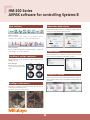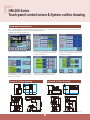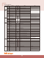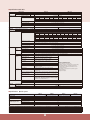
1
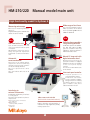
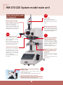
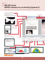
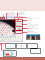
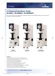
Test Equipment and Seismometers
Micro Vickers Hardness Testing Machines
Catalog No.E17003
Micro Vickers Hardness Testing Machines
HM-200 Series
ith simple touch
-pa
ne
l
A
tion
All-
era
i n-
e
mo
w
del
op
on
Equipped both with the latest optical system
ideal for measuring the dimensions of indentation
and a test-force loading device that lets you set the
The HM-200 series is ideal for quality control
and mechanical characteristic evaluation using
Vickers hardness testing of small areas.
Touch-panel control screen
Features
Touch-panel operation
Measurement of indentation
dimensions using a measuring
microscope
● Positioning using
a manual XY stage unit
●
HM-210A・HM-220A
2
●
n
en
io
reme
nt errors.
Automatic di m
tat
asu
B
den
me
sio
sb
iminates in
n
images
desired test force!
K el
A
P
V
yA
Features
Operation using AVPAK
Automatic measurement of
indentations
● Positioning using
a manual XY stage
●
●
HM-210B・HM-220B
System A
System B
Manual
Manual
Single point
Single point
Manual XY stage
Manual XY stage
Measuring microscope
Automatic (AVPAK)
Monochrome, 300,000 pixels*
Color, 3 million pixels
Touch panel
PC(AVPAK)
Functions
Focusing
Testing action
Test-point positioning
Measuring indentations
Camera (for observing and measuring indentations)
Operating the main unit
*When a video camera unit is used (pixel count of the camera itself: 380,000)
3
HM-210/220 Manual model main unit High-functionality model for Systems A
Wide range of test force
Measuring microscope
Use of an electromagnetic method
makes it possible to set the desired
test force, between 0.4903 mN and
19610 mN. (HM-220)
Microscope for measuring indentation
dimensions
Integrated 10X eyepiece (810-354 video
camera unit can be installed)
New
New
Objective lenses provide a
long working distance
LED illumination unit
Uses an LED illumination unit that
offers a long service life and low power
consumption.
LED illumination reduces the time lost
during the light bulb replacement
required with conventional illumination
units.
Six MH Plan objectives are available.
The 10X, 20X, 50X, and 100X
types are used when measuring
indentations, and the 2X and 5X for
widefield observation tasks.
Manual XY stage unit with
digital micrometer head
Automatic
turret mechanism
During test-site positioning, the
positional information is displayed
digitally and can also be displayed
on the touch panel display
controller
25 × 25 mm or 50 × 50 mm stroke
can be selected.
The positions of the indenter and the
objective lens can be automatically
switched using touch panel operation
(can also be manually switched).
Up to four objective lenses can be
installed.
Up to two indenter shaft units can be
installed.
Color touch panel controller
To u c h p a n e l o p e r a t i o n s f o r
controlling hardness testing
provide a full suite of basic
functions necessary for hardness
testing, a function for converting
the hardness value into various
types of hardness scales, and a
statistical calculation function
Interfacing to
external instruments
Provided with a wide variety of interfaces
to suit any purpose
Test results can be printed on a printer or
output to a PC.
■ USB
2.0 interface (for data communication)
For PC (EXPAK ver6)
■ Digimatic interface For DP-1VR, U-WAVE, and USB-ITN
■ Serial interface For DPU-414
Video camera unit 810-354
(Can be installed in the manual model main unit)
CCD camera and 8.4-inch TFT monitor
Enables observation and measurement of
indentations at high magnification,thereby
reducing operator error
4
HM-210/220 System model main unit
High-functionality model
for Systems B
New
Vision unit
USB color mega-pixel camera
A 3-million pixel, 1/2-inch color
USB camera is used for the system
model.
Measuring microscope
(Can be installed as an option)
Enables magnified observation and
measurement of indentations.
(The vision unit integrated in the
system model main unit and the
measuring microscope cannot be
simultaneously used for observation.)
Wide range of test force
Use of an electromagnetic method
makes it possible to set the desired test
force very accurately, between 0.4903
mN and 19610 mN. (HM-220)
New
New
LED illumination unit
Objective lenses provide a
long working distance
Uses an LED illumination unit that
offers a long service life and low
power consumption.
LED illumination reduces the
time lost during the light bulb
replacement required with
conventional illumination units.
Six MH Plan objectives are available.
The 10X, 20X, 50X, and 100X
types are used when measuring
indentations, and the 2X and 5X for
widefield observation tasks.
2X and 5X for wide-field observation
Automatic turret mechanism
The positions of the indenter
and the objective lens can be
automatically switched from a PC
(AVPAK) (can also be manually
switched). Up to four objective
lenses can be installed.
Up to two indenter shaft units can
be installed.
connection
Manual XY stage unit with
digital micrometer head
(System B)
During test-site positioning, the
positional information is displayed
digitally.
25 × 25 mm or 50 × 50 mm stroke
can be selected.
AVPAK software for automatic hardness
testing systems
New
Software that supports control, testing, and report creation
related to hardness testing
Supports parameter setting and automatic measurement.
High-functionality PC and TFT monitor
Compatible with Windows 7 Professional 32-bit
Supports a wide-screen TFT and provides improved operability.
5
HM-200 Series
AVPAK software for controlling Systems B
Screen layout for control, testing status, and result display can be changed freely.
Graphic view (of stored images)
For displaying the entire specimen and
checking the pattern positioning
The digital zoom function can be used to
easily magnify and check the site being tested.
Pattern creation
Layout view
Photos from individual
views, graphs, tables,
etc., can be laid out
freely to help with report
creation.
Part program
Automatically records the sequence of
operations in a test
To repeat the same test, the part
program can be called up for repeated
execution.
Parts manager
Test result
list view
Hardness curve graph
Hardness distribution diagram
Test result view
6
Pattern pasting
Video view (live image)
Indentation image display
Small indentations can be observed
using the digital zoom function.
Contrast level meter
Stable focusing can be easily
achieved by anyone.
Counter
Displays the stage's current coordinates.
Property panel
Test control
Controls testing actions such as wideor narrow-range auto-focusing and
measurement of indentations.
Turret control
Switches the objective lens and indenter
shaft
Illumination control
Controls the illumination in 100 steps
Indentation-reading example
Pattern panel
Frequency distribution graph
7
HM-200 Series
AVPAK software for controlling Systems B
New functions
Indentation depth display
Displays the indentation depth of the diamond indenter while the
testing force is being applied. (Reference value)
Pattern creation
This tool supports the creation of test patter ns such as
straight lines, zigzag lines, and teaching patter ns.
Pattern pasting
This tool supports the pasting of created test patterns. It adjusts the
origin, direction, etc., to paste a pattern.
Property panel
Used for setting the test conditions such as the test force and load
time, as well as the indentation measurement condition.
Handling of multiple specimens
Multiple specimens can be tested when a part program and Parts
Manager are used.
Parts Manager
Executes a common part program
for specimens having the same
shape
Navigation function
When the test position is being moved during multi-point testing, this
function guides the travel of the XY fine adjustment manual stage to the
next position.
Reading of indentations
Improvement in image-processing performance has improved the
indentation measurement function.
*measurement accuracy varies according to conditions.
8
HM-200 Series
Touch-panel control screen & System outline drawing
Touch-panel control screen
Easy-to-understand graphic display enables intuitive operation. Functions for converting values and compensating for curved surfaces, as well as
a test condition guiding function are all provided as standard features.
(Installed in the manual model main unit)
Displays test conditions and test results.
Used for selecting a conversion scale, entering
a setting for Pass/Fail determination, and
specifying external output.
Used for selecting a conversion scale, entering
a setting for Pass/Fail determination, and
specifying external output.
By entering the specimen thickness and the
presumed hardness, you can set a test force that
satisfies the JIS conditions.
In addition to the test force dwell time, you can
specify loading and unloading testing actions.
You can check the test results in a statistical list.
System A Outline drawing
System B Outline drawing
Unit: mm
600∼
671
301
181
100∼
750
352
600∼
351
370
171
1500
586
216
180
370
383
397
133
740
600∼
595
133 (max. specimen height)
600∼
171
600∼
(1480)
740
940
600∼
(1521)
750
100∼
Unit: mm
* When the 25 × 25 mm manual XY stage is used
* When the 25 × 25 mm manual XY stage is used
9
■System configurations
Code No.
Main unit
Factoryinstalled
options
Essential
options
Details
○
×
Standard test force, measuring microscope, with a 50X lens
810-405*
HM-220 manual model main unit
○
×
Low test force, measuring microscope, with a 50X lens
810-403*
HM-210 system model main unit
×
○
Standard test force, with a 50X lens
810-408*
HM-220 system model main unit
×
○
Low test force, with a 50X lens
11AAC104
Objective lens unit 2X
○
Objective lens, with lens holder
Notes
No measuring microscope, No touch panel
Up to three additional lenses can be selected
(maximum of four lenses can be installed in the main
unit)
11AAC105
Objective lens unit 5X
○
Objective lens, with lens holder
11AAC106
Objective lens unit 10X
○
Objective lens, with lens holder
11AAC107
Objective lens unit 20X
○
Objective lens, with lens holder
11AAC108
Objective lens unit 100X
○
Objective lens, with lens holder
11AAC109
Indenter shaft unit for HM-210
○
With 19BAA061 knoop indenter
Double-indenter specification
11AAC110
Indenter shaft unit for HM-220
○
With 19BAA062 knoop indenter
Double-indenter specification
11AAC129
Measuring microscope
(which can be added)
×
○
810-354*
Video camera unit
○
△
810-420
Manual XY stage unit 25X25
810-423
Manual XY stage unit 50X50
810-424
Manual XY stage unit 1"x1"
☆
☆
810-427
Manual XY stage unit 2"x2"
11AAC063
AVPAK v1 J
11AAC064
AVPAK v1 E
×
☆
Cannot be used simultaneously with the VISION UNIT
Monochrome 300,000-pixel camera, 8.4-inch TFT,
with a stand
Standard vise
○
Jaw opening: 51 mm
○
Jaw opening: 100 mm
810-013
Thin plate specimen holder
○
Thickness: Max. 5 mm
810-014
Slender specimen holder
(horizontal)
○
Diameter: 0.4-3 mm
810-015
Slender specimen holder (vertical)
○
Diameter: 0.4-4 mm
810-019
Specimen-tilting holder
○
Jaw opening: 37 mm, Tilting angle: ±15°,
Rotating angle: ±25°
810-020
Universal specimen holder
○
Thickness: Max. 30 mm
810-018
Turntable
○
Minimum graduation: 1°
810-085
Adjustable thin-plate specimen holder
○
Thickness: Max. 3 mm, Width: Max. 56 mm
810-095
Rotatable tilting specimen holder
○
810-870*
Specimen heater HST-250
810-650-1
Resin-molded specimen holder Ø25.4
○
Ø25.4±0.5 mm Specimen height: 9-39 mm
810-650-2
Resin-molded specimen holder Ø30
○
Ø30±0.5 mm Specimen height: 9-39 mm
810-650-3
Resin-molded specimen holder Ø31.75
○
Ø31.75±0.5 mm Specimen height: 9-39 mm
810-650-4
Resin-molded specimen holder Ø38.1
○
Ø38.1±0.5 mm Specimen height: 9-39 mm
810-650-5
Resin-molded specimen holder Ø40
○
Ø40±0.5 mm Specimen height: 9-39 mm
19BAA061
Knoop indenter (for standard test force)
○
○
△: Installation requires a measuring microscope.
Provided on a special order basis
Selected according to the delivery destination
Special vise
Height: Min. 20 mm, Width and diameter: 15-55 mm
△: Cannot be automatically read with AVPAK
△
Can be selected to replace the Vickers indenter
provided as a standard accessory.
19BAA062
Knoop indenter (for low test force)
375-056
Objective micrometer
×
○
Scale graduation: 1 mm, Minimum graduation: 0.01 mm
For magnification calibration
02AGD600*
Model DPU-414
(with a connection cable)
○
×
Receipt printer
For 100V
264-504*
Model DP-1VR
○
×
Digimatic mini-processor
936937
Connection cord
○
×
For DP-1VR 1 m
02AZD810D U-WAVE-R
○
×
02AZD880D U-WAVE-T
○
×
Dedicated connection cable for
02AZD790D
U-WAVE-T
○
×
06ADV380D USB-ITN-D
○
×
○
×
−
Others
System A System B
HM-210 manual model main unit
Special
810-016
accessories
810-017
Printers
Item name
810-400*
EXPAK ver6
○
Buzzer type
Flat 10-pin
PC must be provided separately.
Requires Microsoft Excel 2010
02ATE760
Table
○
998923
System rack (vertical)
○
810-641
Vibration isolator
○
Only the tester can be mounted.
Recommended if the video camera unit is to be
attached
810-644
Wing for vibration isolator
○
11AAC146
Plate for preventing toppling
○
1800(W)x900(D)x740(H)
For tester and PC
Only a PC can be mounted.
For 810-641
○: Selectable ☆: One of each type must be selected from the choice offered ×: Cannot be selected △: Contact Mitutoyo Sales Dept.
Note: A suffix replaces the * symbol.
10
■Specifications Main Unit
Model name
HM-210 manual model main unit
HM-210 system model main unit
Hardness tester
Applicable standards
Test force
Main unit
HM-210A
HM-210B
○
−
−
○
810-401*
810-403*
JIS B 7725 / ISO 6507-2
Hardness
symbol
N
(gf)
HV0.01
98.07x10⁻³
(10)
HV0.02
196.1x10⁻³
(20)
HV0.03
294.2x10⁻³
(30)
Indenter approach speed
Test force loading time
Test force dwell time
Test force unloading time
Model name
HM-220 manual model main unit
HM-220 system model main unit
Hardness tester
Applicable standards
Test force
Main unit
Test force loading time
Test force dwell time
Test force unloading time
Controller
Test force control
Test force switching
Drive method
Operation method
Number of turret ports
Display
content
Indentation value
Minimum display unit
Hardness value
Test condition
Compensation
Pass/Fail determination
Other
Calculation
functions
HV0.2
1.961
(200)
HV0.3
2.942
(300)
HM-220A
HM-220B
○
−
−
○
810-405
810-408
Indenter approach speed
Loading
device
Turret
HV0.1
980.7x10⁻³
(100)
HV0.5
4.903
(500)
HV1
9.807
(1000)
Fixed at 60 μm/s
1- 99s Can be set in 1s increments.
0-999s Can be set in 1s increments.
1- 99s Can be set in 1s increments.
JIS B 7725 / ISO 6507-2
Hardness
symbol
N
(gf)
Hardness
symbol
N
(gf)
Mechanism
HV0.05
490.3x10⁻³
(50)
Language used
Pass/Fail determination function
Function for guiding measurement
condition setup
Compensation function
Statistical calculation function
External connection interface
Maximum specimen dimensions
Maximum load capacity
Main unit
External dimensions
(excluding protrusions and stage)
Main unit mass
Main unit power supply
Note: A suffix replaces the * symbol.
HV0.00005 HV0.0001
HV0.0002
HV0.0003
HV0.0005
HV0.001
HV0.002
HV0.003
HV0.005
HV0.01
0.4903x10⁻³ 0.9807x10⁻³ 1.961x10⁻³
(0.05)
(0.1)
(0.2)
2.942x10⁻³
(0.3)
4.903x10⁻³
(0.5)
9.807x10⁻³
(1)
19.61x10⁻³
(2)
29.42x10⁻³
(3)
49.03x10⁻³
(5)
98.07x10⁻³
(10)
HV0.02
HV0.03
HV0.05
HV0.1
HV0.2
HV0.3
HV0.5
HV1
HV2
196.1x10⁻³
(20)
294.2x10⁻³
(30)
490.3x10⁻³
(50)
980.7x10⁻³
(100)
1.961
(200)
2.942
(300)
4.903
(500)
9.807
(1000)
19.61
(2000)
Variable between 2 and 60 μm/s Can be set in 1μm/s increments
(only for 30 gf or smaller; Fixed at 60 μm/s for 31 gf or greater)
1- 99s Can be set in 1s increments.
0-999s Can be set in 1s increments.
1- 99s Can be set in 1s increments.
Electromagnetic (voice coil)
Can be selected from touch panel
Motor drive
Touch panel / Manual
AVPAK / Manual
Indenter shaft unit: Up to two can be installed (including the standard Vickers indenter shaft unit already installed); Objective lens
unit: Up to four can be installed (including the standard 50X objective lens already installed)
Integrated touch panel (5.7-inch color LCD)
Data-processing software
D1 D2, max. 5 digits each
For objective lenses of 50X or higher: 0.01 μm;
For lower than 50X: 0.1 μm
Maximum of four digits, Minimum: 0.1 HV/HK,
Fracture toughness value
Indenter (HV/HK), test force, loading, dwell,
and unloading times
Software (AVPAK) functions
Cylinder, sphere, measurement
・Tester and turret control functions
・Hardness conversion, compensation for curved surface,
OK/±NG
Pass/Fail determination, and statistical calculation
XY positional data, turret position display,
・measurement of indentations, illumination control
statistical calculation
・
Contrast level meter
Japanese, English, German, French, Italian, Spanish
・Specification of test pattern and coordinate system
Determines whether or not the measured hardness is
acceptable (OK/±NG) based on the upper and lower limits that ・Simple operations
・Analysis and report
have been set.
Enter the indenter, specimen thickness, and presumed hardness
to calculate the maximum test force.
Cylindrical compensation, spherical compensation,
measurement compensation
Number of data units, maximum value, minimum value,
average, range, upper limit, lower limit, number of passes,
number of fails, ultra upper limit and ultra lower limit, standard
deviation (n-1), standard deviation (n)
For printer: Serial interface (compatible with the RS-232C standard); For Digimatic interface and data communication: USB 2.0
Maximum specimen depth: 160 mm, Maximum specimen height: 133 mm
3kg
Approx. 315 (W) x 671 (D) 595 (H) mm
Approx. 315 (W) x 586 (D) 741 (H) mm
Approx. 43 kg
39VA AC100V: AC100-125V, AC200V: AC220-240V
■Specifications Optical system
Item name
Optical system
Tube lens magnification
Illumination
Standard objective lens
Light source
Aperture diaphragm
Lens
Working distance [mm]
Real field of view and imaging range
Measuring microscope (Ocular)
Objective lens unit (including holder) (factory-installed options)
Part No.
Working distance [mm]
Measurement range [Ø mm]
Imaging range [(H) mm x 0.089 (V) mm] (Vision unit)
HM-210
HM-220
HM-210
HM-220
system model main unit
system model main unit
manual model main unit manual model main unit
Infinitely corrected optical system, 4-port objective lens switching method
1x
White LED
Variable
MH Plan 50x
2.5
Real field of view: ø0.14 mm
Imaging range: 0.118 (H) mm x 0.089 (V) mm
Length-measuring microscope with integrated
Factory-installed options
encoder and eyepiece (10X)
MH Plan 2x
11AAC104
6
3.5 (reference)
2.95x2.21
MH Plan 5x
11AAC105
27
1.4 (reference)
1.18x0.89
11
MH Plan 10x
11AAC106
11.8
0.7
0.59x0.44
MH Plan 20x
11AAC107
5.2
0.35
0.30x0.22
MH Plan 100x
11AAC108
1.5
0.07
0.059x0.044
■Specifications Manual XY stage unit
■Specifications Video camera unit
Systems A and B
Item name
System A
Manual XY
Manual XY
stage unit 1"x1" stage unit 2"x2"
Code No.
Manual XY
stage 25X25
Manual XY
stage 50X50
Item
Description
TFT screen
magnification
10X: Approx. 200 times (approx. 260 times)
50X: Approx. 1000 times (approx. 1300 times)
100X: Approx. 2000 times (approx. 2600 times)
Imaging method: EIA
Imaging device: 1/3-inch interline CCD
External dimensions:31(W)x72.5(D)x29(H)mm
Mass;85g
Screen size: 210.4 mm diagonal (8.4-inch)
Number of pixels:640(H)x480(V)
Rotation range:350°
Tilting range:-5-40°
Power supply:AC100-230V50/60Hz
Power consumption:12VA
External dimensions:228(W)x61.5(D)x195(H)mm
[232 (W) × 227 (D) × 426.5 (H) mm (when installed on the stand)]
Mass: 1.8 g (4.2 kg including the stand)
810-424
810-427
810-420
810-423
Stage travel
range
25.4×25.4mm
50.8×50.8mm
25×25mm
50×50mm
Table size
100×100mm
130×130mm
100×100mm
130×130mm
Minimum
display unit
XY stage
dimensions
XY stage
mass
0.001mm/0.0005"
CCD camera
TFT monitor
0.001mm
221(W)×221(D)
×37(H)mm
305(W)×305(D)
×49(H)mm
221(W)×221(D)
×37(H)mm
305(W)×305(D)
×49(H)mm
2.5kg
6.6kg
2.5kg
6.6kg
■Standard accessories
Item name
Diamond indenter*1
*1
Diamond indenter
Hardness testing block*2
Indenter shaft unit*1
Objective lens unit 50X*1
Spacer
Extension shaft
Extension shaft
Dust cover
Plastic Phillips screwdriver
Precision flathead screwdriver
Hex-head screwdriver
Hex-head screwdriver
Hex wrench
Hex wrench
Holder
Cap*1
Cable clamp
Cable clamp
Spiral tube
Power supply cord set -PSE
AC cord set-UL/CSA
AC cord set-UL/CSA
AC cord set-UL/CSA
AC cord set-UL/CSA
AC cord set-UL/CSA
User's manual for the manual model main unit
User's manual for the manual model main unit
User's manual for the system model main unit
User's manual for the system model main unit
Material: Bakelite 11 (W) × 42 (D) × 13 (H) mm
For elevation shaft: 38 mm With two set screws
For elevation shaft: 76 mm With two set screws
For the hardness tester main unit
No.1300 Phillips 2×100
No.205 flathead 1.2
1.5 mm
2.5 mm
2.5 mm
3.0 mm
Hanger bolt for the main unit
Cap for the holder
Gray
Black
Black, approx. 2 m
Classification: Unmarked/C
Classification: A
Classification: D
Classification: E
Classification: DC
Classification: K
Japanese
English
Japanese
English
11AAC198
Configuration disk
For the system main unit
11PAA074
Accessory case
Certificate for the tester
Certificate for the hardness test block
Warranty
USB camera (system main unit)*1
In both Japanese and English
In both Japanese and English
In both Japanese and English
3 million pixels, 1/2-inch color Systems B
−
−
−
19BAA133
11AAB405
11AAB406
02DEA471
−
−
−
−
−
−
−
−
−
−
−
02ZAA000
02ZAA010
02ZAA020
02ZAA030
02ZAA040
02ZAA050
99MBG127J
99MBG127A
99MBG137J
99MBG137A
−
−
−
−
Specification/Remarks
Vickers for HM-210
Vickers for HM-220
700HMV0.3 25 mm (diameter) × 6 mm (thickness)
With Vickers indenter
Quantity
1
1
1
1
1
1
1
1
1
1
1
2
1
1
4
4
2
2
1
1
Depends on the delivery destination
1
Depends on the delivery destination
1
Depends on the model
1
1
1
1
1
*1 Already installed in the main unit when it is delivered.
*2 The numeric values shown are nominal; actual values will be slightly above or below the nominal values.
Distributed by:
Quality Solutions Hardness Testers
Stocking distributor and certified calibration
1015 Old Forest Rd., Corydon, IN 47112
Tel: 812-704-5491, Fax: 812-734-3263
www.qs-hardnesstester.com
Note: All information regarding our products, and in particular the illustrations, drawings, dimensional and performance data contained in this pamphlet, as well as other
technical data are to be regarded as approximate average values. We therefore reserve the right to make changes to the corresponding designs, dimensions and weights.
The stated standards, similar technical regulations, descriptions and illustrations of the products were valid at the time of printing. Only quotations submitted by ourselves
may be regarded as definitive.
Our products are classified as regulated items under Japanese Foreign Exchange and Foreign Trade Law. Please consult us in advance if you wish to export our products to
any other country. If the purchased product is exported, even though it is not a regulated item (Catch-All controls item), the customer service available for that product
may be affected. If you have any questions, please consult your local Mitutoyo sales office.
Export permission by the Japanese government may
be required for exporting our products according to
the Foreign Exchange and Foreign Trade Law. Please
consult our sales office near you before you export
our products or you offer technical information to a
nonresident.
000 1207(1)X-(CH)X, Printed in Japan
Code No.
19BAA058
19BAA059