1
R S F S u p e rmini Actuato r
RSF Brushless Servo Actuator
Total Motion Control
Precision Gearing & Motion Control
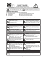
SAFETY GUIDE
For actuators, motors, control units and drivers
manufactured by Harmonic Drive LLC
Read this manual thoroughly before designing the application, installation, maintenance or inspection of the actuator.
WARNING
Indicates a potentially hazardous situation, which, if
not avoided, may result in minor or moderate personal
CAUTION injury and/or damage to the equipment.
Indicates a potentially hazardous situation,
which, if not avoided, could result in death
or serious personal injury.
LIMITATION OF APPLICATIONS:
The equipment listed in this document may not be used for the applications listed below:
Space equipment
Automobile, automotive parts
Aircraft, aeronautic equipment
Amusement equipment, sport equipment, game machines
Nuclear equipment
Machine or devices acting directly on the human body
Household apparatus
Instruments or devices to transport or carry people
Vacuum equipment
Apparatus or devices used in special environments
If the above list includes your intending application for our products, please consult us.
Safety measures are essential to prevent accidents resulting in death, injury or damage of the equipment due to
malfunction or faulty operation.
CAUTIONS FOR ACTUATORS AT APPLICATION DESIGNING
Always use under followings conditions:
-Ambient temperature: 0˚C to 40˚C
-Ambient humidity: 20% to 80%RH (Non-condensation)
-Vibration: Max 24.5 m/S2
CAUTION -No contamination by water, oil
-No corrosive or explosive gas
Follow exactly the instructions in the relating
manuals to install the actuator in the equipment.
CAUTION
-Ensure exact alignment of actuator shaft center and
corresponding center in the application.
Failure to observe this caution may lead to vibration,
resulting in damage of output elements.
CAUTION FOR ACTUATORS IN OPERATIONS
Keep limited torques of the actuator.
-Keep limited torques of the actuator.
-Be aware, that if arms attached to output element hits
by accident an solid, the output element may be
WARNING
CAUTION uncontrollable.
Do not apply impacts and shocks
Never connect cables directly to a power supply
socket.
-Each actuator must be operated with a proper driver.
-Failure to observe this caution may lead to injury, fire or
damage of the actuator.
Avoid handling of actuators by cables.
-Do not use a hammer during installation
-Failure to observe this caution could damage the
WARNING
WARNING encoder and may cause uncontrollable operation.
-Failure to observe this caution may damage the wiring,
causing uncontrollable or faulty operation.
CAUTIONS FOR DRIVERS AT APPLICATION DESIGNING
Always use drivers under followings conditions:
Use sufficient noise suppressing means and safe
-Mount in a vertical position keeping sufficient distance
grounding.
to other devices to let heat generated by the driver
-Keep signal and power leads separated.
radiate freely.
-Keep leads as short as possible.
-Ambient temperature: 0˚C to 50˚C
CAUTION -Ground actuator and driver at one single point, minimum
CAUTION
-Ambient humidity: less than 95% RH (Non
ground resistance class: D (less than 100 ohms)
condensation)
-Do not use a power line filter in the motor circuit.
-No contamination by water, oil or foreign matters
-No corrosive, inflammable or explosive gas
Pay attention to negative torque by inverse load.
–Inverse load may cause damages of drivers.
Use a fast-response type ground-fault detector
designed for PWM inverters.
-Please consult our sales office, if you intent to apply
CAUTION
CAUTION products for inverse load.
-Do not use a time-delay-type ground-fault detector.
CAUTION FOR DRIVERS IN OPERATIONS
Never change wiring while power is active.
Do not touch terminals or inspect products at least
-Make sure of power non-active before servicing the
5 minutes after turning OFF power.
products.
-Otherwise residual electric charges may result in
-Failure to observe this caution may result in electric
WARNING electric shock.
WARNING shock or personal injury.
-Make installation of products not easy to touch their
inner electric components.
Do not make a voltage resistance test.
-Failure to observe this caution may result in damage of
the control unit.
-Please consult our sales office, if you intent to make a
CAUTION voltage resistance test.
Do not operate control units by means of power
ON/OFF switching.
-Start/stop operation should be performed via input
CAUTION signals.
Failure to observe this caution may result in deterioration
of electronic parts.
DISPOSAL OF AN ACTUATOR, A MOTOR, A CONTROL UNIT AND/OR THEIR PARTS
All products or parts have to be disposed of as industrial waste.
-Since the case or the box of drivers have a material indication, classify parts and dispose them separately.
CAUTION
1
RSF supermini series AC servo actuator manual
Contents
Chapter 1 Overview of the RSF supermini series ................................................................................... 1
1-1
Major characteristics................................................................................................................... 1
1-2
Ordering information ................................................................................................................... 2
1-3
Combinations with drivers .......................................................................................................... 2
1-4
Specifications of RSF supermini actuators ................................................................................. 3
1-5
External dimensions of actuators ............................................................................................... 4
1-6
One-way positioning accuracy.................................................................................................... 6
1-7
Torsional stiffness ....................................................................................................................... 7
1-8
Detector resolution...................................................................................................................... 8
1-9
Mechanical accuracy .................................................................................................................. 8
1-10 Allowable load............................................................................................................................. 9
1-10-1 Allowable radial load and allowable thrust load............................................................. 9
1-10-2 Radial load when the operating point is different........................................................... 9
1-11 Rotary direction......................................................................................................................... 10
1-12 Impact resistance...................................................................................................................... 10
1-13 Vibration resistance .................................................................................................................. 10
1-14 Torque-speed characteristics.....................................................................................................11
1-15 Cable specifications.................................................................................................................. 13
Chapter 2 Selection of the RSF supermini Series................................................................................. 14
2-1
Allowable load moment of inertia.............................................................................................. 14
2-2
Variable load inertia .................................................................................................................. 14
2-3
Verifying loads .......................................................................................................................... 14
2-4
Duty cycles ............................................................................................................................... 15
2-4-1 Actuator speed................................................................................................................ 15
2-4-2 Load moment of inertia ................................................................................................... 15
2-4-3 Load torque..................................................................................................................... 15
2-4-4 Acceleration time and deceleration time......................................................................... 16
2-4-5 Calculating equivalent duty............................................................................................. 17
2-4-6 Effective torque and average speed............................................................................... 21
2-4-7 Permissible overloaded time .......................................................................................... 22
Chapter 3 Installing the actuator ......................................................................................................... 23
3-1
Receiving Inspection................................................................................................................. 23
3-2
Notice on handling .................................................................................................................... 24
RSF-super_V1_01
- contents 1 -
RSF supermini series AC servo actuator manual
3-3
Location and installation ........................................................................................................... 25
3-3-1 Environment of location .................................................................................................. 25
3-3-2 Considerations into External Noise ................................................................................ 25
3-3-2 Installation....................................................................................................................... 26
Chapter 4 Motor shaft retention brake(RSF-5A) ................................................................................... 27
4-1
Motor shaft retention brake specifications ................................................................................ 27
4-2
Controlling the brake power supply .......................................................................................... 27
4-2-1 Using a relay cable (Recommended method) ................................................................ 27
4-2-2 Not using a relay cable ................................................................................................... 28
Chapter 5 Options ................................................................................................................................. 29
5-1
Relay cables ............................................................................................................................. 29
5-2
Relay cable wire bound specifications...................................................................................... 30
5-3
Connectors ............................................................................................................................... 31
Appendix 1 Conversion of Unit ...................................................................................................App. 1-1
Appendix 2 Moment of inertia .....................................................................................................App. 2-1
1. Calculation of mass and moment of inertia .................................................................App. 2-1
2. Moment of inertia of circular cylinder...........................................................................App. 2-3
RSF-super_V1_01
- contents 2 -
Chapter 1 Overview of the RSF supermini series
Chapter 1 Overview of the RSF supermini series
The RSF supermini series are ultra-small AC servo actuators combining ultra-precision control
deceleration device Harmonic Drive® that provides precision rotation operation at a high torque with
ultra-small AC servo motor developed to make use of the performance of the decelerator.
Actuators with an electromagnetic brake are also included in the lineup. They can meet fail-safe
requirements of equipment to prevent accidents upon power supply failure.
The dedicated servo driver HA-680 is an AC servo driver for 24VDC power supply. The small and
multi-functional HA-680 driver is equipped with position control, speed control, and torque control as
standard to control operation of the RSF supermini series correctly and precisely.
The RSF supermini series can contribute to downsizing of driving of robot joints, semiconductor/LCD
panel manufacturing equipment, machine tools, and other FA equipment. By utilizing its small and
high-torque characteristics, it can also be used for small equipment and for research.
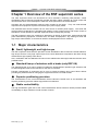
1-1 Major characteristics
◆
Small, lightweight, and high-torque
The RSF supermini series with the precision-control deceleration device Harmonic Drive® realizes a
high torque and has a very high output torque for the outer dimensions compared to the direct driving
method with a high-capacity motor alone.
Also, combination with the dedicated AC servo motor realizes size and weight reduction that are never
possible before.
◆
Standard lineup of actuators with a brake (only RSF-5A)
The standard lineup of AC servo actuators includes the deenergisation operation type actuators with
an electromagnetic brake for the first time for this size of actuators.
Fail-safe requirements of equipment can be met to prevent accidents upon power failure without
providing any external brake or changing the equipment structure to install a brake.
◆
Superior positioning precision
The characteristics of the control deceleration device Harmonic Drive® such as non-backlash and
superior positioning precision realize high-precision mechanisms.
◆
Stable controllability
The high deceleration gear ratio of the control deceleration device Harmonic Drive® provides stable
controllability for large variations of load moment of inertia.
RSF-Super_V1_02
-1-
Chapter 1 Overview of the RSF supermini series
1-2 Ordering information
Model codes for the RSF supermini series actuators are as follows:
RSF-5 A-50-E 050-C
Model: AC servo actuator
RSF series: Output shaft is of the shaft type.
Frame size: 3 or 5
Design version
Reduction ratio of gearing
30:
1/30
50:
1/50
100: 1/100
Encoder specifications
US: 14 wire incremental encoder (standard)
E: 4 wire incremental encoder (optional)
Encoder pulses on motor shaft
020: 200p/rev (Model 3)
050: 500p/rev (Model 5)
Specifications
C:
Standard item(with connector)
BC: With brake(with connector)
SP* Special specification
1-3 Combinations with drivers
The RSF supermini series actuators are used in combination with the HA-680-4B-24 driver.
The HA-680 driver can perform position control, speed control, and torque control.
For details of the driver, refer to “AC Servo Driver for 24VDC Power Supply HA-680 Series Technical
Data.”
The optional relay cable is required for connection between the actuator and the driver.
RSF-Super_V1_02
-2-
Chapter 1 Overview of the RSF supermini series
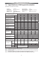
1-4 Specifications of RSF supermini actuators
Specifications of actuators are as follows:
Time rating:
Excitation method:
Insulation class:
Withstanding voltage:
Insulation resistance:
Structure:
Continuous
Service temperature:
0~40˚C
Permanent
type
Storage
Chaptermagnet
1 Overview
of the
RSF temperature:
supermini series-20~+60˚C
B
Service/ storage humidity: 20~80%RH (no condensation)
2
AC500V/min
Vibration resistance:
49m/s
DC500V 100MΩor more
Lubricant:
Grease (Harmonic Grease)
Totally enclosed self cooling
type
1-4 Specifications of RSF supermini actuators
Specifications of actuators are as follows:
RSF-3A
Model
Item
30
50
PowerTime
Supply
Voltage
rating:
V
Continuous
Excitation
method:
Permanent
type
Allowable
Continuous
Current
A magnet 0.68
Insulation class:
B
Allowable Continuous Torque
N•m
0.03
Withstanding voltage:
AC500V/min
(during operation at allowable
Insulation
resistance:
DC500V
100MΩor more
Kgf•cm
0.31
continuous
rotation
speed)
Structure:
Totally enclosed self cooling
Allowable Continuous Rotation Speed
type r/min
150
Instantaneous Maximum Current
Maximum Torque
Maximum Speed
Torque Constant
MEF constant
Phase Resistance (at 20˚C)
Phase Inductance
Moment of Inertia
Note 4
100
DC24
Service
30
temperature:
Storage temperature:
0.63
0.49
Service/ storage humidity:
0.06
0.08
Vibration resistance:
Lubricant: 0.82
0.61
(output shaft)
Allowable Continuous Stall Torque
RSF-5A
50
100
DC24
0~40˚C
-20~+60˚C 0.92
1.11
0.76
20~80%RH (no condensation)
2
0.18
0.29
0.44
49m/s
Grease (Harmonic
1.83
2.95 Grease)4.48
90
45
150
90
45
N•m
0.04
0.08
0.12
0.28
0.44
0.65
kgf•cm
0.41
0.82
1.22
2.85
4.48
6.62
A
1.2
1.1
0.8
2.3
2.2
1.7
N•m
0.09
0.15
0.21
0.5
0.9
1.4
kgf•cm
0.92
1.53
2.14
5.10
9.17
14.3
r/min
333
200
100
333
200
100
N•m/A
0.11
0.18
0.40
0.30
0.54
1.1
kgf•cm/A
1.12
1.84
4.08
3.06
5.51
11.22
V/(r/min)
0.015
0.025
0.050
0.04
0.07
0.13
Ω
1.34
mH
0.18
0.82
0.27
GD2/4
kg•m2
0.11x10⁻⁴
0.29x10⁻⁴
1.17x10⁻⁴
0.66x10
(0.11x10⁻³)
1.83x10⁻⁴
(0.31x10⁻³)
7.31x10⁻⁴
(1.23x10⁻³)
J
kgf•cm•s2
1.07x10⁻⁴
2.98x10⁻⁴
11.90x10⁻⁴
0.67x10⁻³
(1.13x10⁻³)
1.87x10⁻⁴
(3.15x10⁻³)
7.45x10⁻³
(12.6x10⁻³)
50
100
30
50
100
Gear ratio
30
N
Allowable Radial Load
(output shaft central value)
Allowable Thrust Load
Encoder Pulses (motor shaft)
Encoder Resolution
(Output shaft: when multiplied by 4)
Note 5
-4
40
90
kgf
4.0
9.1
N
130
270
kgf
13.2
27.5
Pulse
200
500
Pulse/
Rotation
24,000
40,000
80,000
60,000
100,000
200,000
Input
Power
Note 1: The table shows
typical output
values—of actuators.—
V
—
DC24
Supply
Note
2:
The
values
in
the
table above are obtained whenit is combined with the combined driver (HA-680-4B-24).
Voltage
Motor Shaft Brake
Note 3: All values are typical.
N•m
—
—
—
0.18
0.29
0.44
Note 4: The moment Retention
of inertia is the total value of the motor shaft and Harmonic Drive moment of inertia values
Torque
kgf•cm
—
—
—
1.83
2.95
4.48
converted to the output side. The values in parentheses are for equipment with a brake.
Note 5: The encoder w/o
resolution
is (motor
shaft encoder resolution when multiplied by 4)
x (except
(gear ratio).
brake
g
66.0
clamp filter)
Mass
Combined Driver
w/ brake
g
31.0 (except clamp filter)
HA-680-4B-24
Note 1:
Note 2:
Note 3:
Note 4:
86.0 (except clamp filter)
HA-680-4B-24
The table shows typical output values of actuators.
The values in the table above are obtained whenit is combined with the combined driver (HA-680-4B-24).
All values are typical.
The moment of inertia is the total value of the motor shaft and Harmonic Drive moment of inertia values
converted to the output side. The values in parentheses are for equipment with a brake.
Note 5: The encoder resolution is (motor shaft encoder resolution when multiplied by 4) x (gear ratio).
- 3-b -3-
Chapter 1 Overview of the RSF supermini series
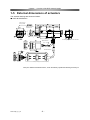
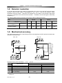
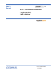
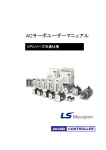
1-5 External dimensions of actuators
The external drawings are shown as follows:
■ RSF-3B-XXX-E020-C
4-M1.6 tap 3.2
evenly spaced
0
φ3.5 h6 -0.008
φ12 h7
0
-0.018
Maximum diameter
of rotation part
Motor lead wire
Line locating range of Encoder cable wire
Encoder lead wire
Clamp filter(2) ZCAT1518-0730(TDK)
Note) For detailed outside dimensions, check the delivery specification drawing issued by us.
RSF-Super_V1_02
-4-
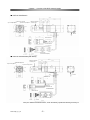
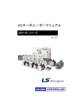
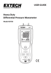
Chapter 1 Overview of the RSF supermini series
■ RSF-5A-XXX-E050-C
3-M2x3 evenly spaced
3-φ2x2.5 evenly spaced
2-φ2.3 evenly spaced
Maximum diameter
of rotation part
FG line
Motor lead wire
Encoder lead wire
Clamp filter
ZCAT1518-0730(TDK)
■ RSF-5A-XXX-E050-BC
■ RSF-5A-XXX-E050-BC(with brake)
Maximum diameter
of rotation part
3-M2x3 evenly spaced
2-φ2.3 evenly spaced
3-φ2x2.5 evenly spaced
FG line
Motor lead wire
Motor and
Brake lead wire
Encoder lead wire
Brake lead wire
Clamp filter
ZCAT1518-0730(TDK)
Note) For detailed outside dimensions, check the delivery specification drawing issued by us.
RSF-Super_V1_02
-5-
Chapter 1 Overview of the RSF supermini series
1-6 One-way positioning accuracy
The following table shows the “one-way positioning accuracy” and “repeated positioning accuracy.”
The following table contains representing values. (JIS B 6201:1987)
The one-way positioning accuracy of RSF supermini actuators is almost equal to the angular
positioning accuracy of the Harmonic® drive gearing, because the effect on the positioning error of the
built-in motor is reducted to its 1/30 or 1/50 or 1/100 by the gearing.
The accuracy for each gear ratio is shown below.
Mode
RSF-3B
Gear ratio
Item
One-way positioning accuracy
30
50
arc min
100
10
rad
2.9×10
RSF-5A
30
50
4
-3
1.20×10
100
3
-3
0.87×10
3
-3
0.87×10
-3
■ Reference
(Accuracy display and measurement method according to JIS B 6201: 1987)
Positional difference
● One-way positioning of rotation shaft motion
First, perform positioning at any one position in a fixed
direction. This position is the reference position. Next,
perform positioning in succession in the same direction,
and measure the difference between the angle actually
rotated from the reference position and the desired angle
at each position. The maximum difference in one
rotation among these values is taken as the
measurement value. Measurement of equipment with
the continuous positioning function for rotational motion
shall be done once per 30 degrees or 12 positions
throughout the entire rotation range as a rule.
One-way positioning
accuracy
Actual position
Start position
RSF-Super_V1_02
-6-
Chapter 1 Overview of the RSF supermini series
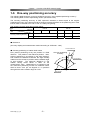
1-7 Torsional stiffness
When a torque is applied to the output flange of the actuator with the motor locked, the resulting
torsional wind up is near proportional to the torque.
The upper right figure shows the torsional stiffness
characteristics of the output flange applying torque starting
from zero to plus side [+T0] and minus side [–T0]. This
trajectory is called torque-torsion characteristics which
typically follows a loop 0→A→B→A’→B’→A as illustrated.
The torsional stiffness of the RSF supermini actuator is
expressed by the slope of the curve that is a spring rate
(wind-up) (unit:N・m/rad).
The torsional stiffness may be evaluated by dividing
torque-torsion characteristics curve into three major regions.
The spring rate of each region is expressed K1, K2, and K3
respectively.
K1: spring rate for torque region 0-T1
K2: spring rate for torque region T1-T2
K3: spring rate for torque region over T2
The wind-up for each region is expressed as follows:
T
◆ wind-up for torque region 0-T1:
ϕ=
K1
T − T1
ϕ = θ1 +
◆ wind-up for torque region T1-T2:
K2
◆
wind-up for torque region over T2:
ϕ = θ2 +
T − T2
K3
The following table shows average values of T1 through T3, K1 through K3, and θ1 through θ2 for
different gear ratios.
Model
RSF-3B
Gear ratio
Symbol
T1
K1
θ1
T2
K2
θ2
K3
Nm
Kgf m
Nm/rad
Kgf m/arc min
x10-4 rad
arc min
Nm
Kgf m
Nm/rad
Kgf m/arc min
x10-4 rad
arc min
Nm/rad
Kgf m/arc min
RSF-Super_V1_02
RSF-5A
30
50
100
30
50
100
0.016
0.0016
27
0.0008
5.9
2.0
0.05
0.005
40
0.0012
12.5
4.2
51
0.0015
0.016
0.0016
30
0.0009
5.3
1.8
0.05
0.005
47
0.0014
10.6
3.6
57
0.0017
0.016
0.0016
34
0.0010
4.7
1.6
0.05
0.005
54
0.0016
9.3
3.1
67
0.0020
0.075
0.0077
90
0.003
8.7
3
0.22
0.022
110
0.003
22
7.5
120
0.004
0.075
0.0077
110
0.003
6.9
2.4
0.22
0.022
140
0.004
18
6
170
0.005
0.075
0.0077
150
0.004
5
1.7
0.22
0.022
180
0.005
13
4.4
200
0.006
-7-
Chapter 1 Overview of the RSF supermini series
1-8 Detector resolution
An encoder with 500 pulses per rotation is incorporated in the motor unit of the RSF supermini series
actuators, and the motor output is decelerated by 1/30, 1/50, or 1/100 by the precision control
decelerator Harmonic Drive®. Therefore, the resolution per one rotation of the actuator output shaft
is 30, 50, or 100 times of the actual encoder resolution. In addition, the encoder signal is electrically
multiplied by 4.
The following table shows the resolution at the output shaft for different gear ratios.
Model
RSF-3B
Gear ratio
Item
RSF-5A
30
50
100
30
50
100
Detector resolution
(when multiplied by 4)
Pulse/Rotation
24,000
40,000
80,000
60,000
100,000
200,000
Angle per one pulse
Angle second
(arc sec)
54
32.4
16.2
21.6
12.96
6.48
1-9 Mechanical accuracy
The machining accuracy of the output flange and the mounting flange of RSF supermini actuators are
indicated in the table below.
RSF-3B
Machined accuracy of the output flange
Symbol
Machined parts
Model
RSF-5A
* T.I.R.
unit: mm
Accuracy value
RSF-3B
a
b
c
d
RSF-5A
Runout of the tip of the output shaft
0.03
0.03
Concentricity of installed spigot joint
0.02
0.04
Squareness of installation surface
0.02
0.02
Output flange surface contact
0.005
0.005
Parallelism of installation surface
e
0.015
0.015
and output flange
*) T.I.R(Total Indicator Reading): Indicates the total amount of dial gage reading when the measurement unit is
rotated once.
RSF-Super_V1_02
-8-
Chapter 1 Overview of the RSF supermini series
1-10 Allowable load
1-10-1 Allowable radial load and allowable thrust load
The gear head used in the RSF supermini series incorporates the high-precision 4-point contact ball
bearing for direct support of external load (output part).
La
LR
The allowable radial load and thrust load of the
output shaft are shown below.
The allowable radial load Fr is obtained with
respect to the center (L/2) 0 point of the output
shaft.
The values in the following table are designed
by considering the life of the bearing.
0 point
FS
The allowable values must not be exceeded.
Fr
FR
L/2
L
Model
Allowable radial load (Fr)
Allowable thrust load (FS)
Unit
N
kgf
N
kgf
RSF-3B
36
3.6
130
13
RSF-5A
90
9.1
270
27
1-10-2 Radial load when the operating point is different
If the operating point of radial load is different, the allowable radial load value is also different.
The relation between radial load position LR and allowable radial value FR is obtained from the
following formula.
The allowable values must not be exceeded.
FR =
FR
Fr
La
LR
L
La
Fr
La + LR
: Allowable radial load at distance LR from the 0 point [N]
: Allowable radial load at the 0 point [N]
: Distance from the bearing starting point to the 0 point [mm]
: Distance from the position where radial load is exerted to the 0 point [mm]
: Shaft length [mm]
Model
Allowable radial load (Fr)
La
L
RSF-Super_V1_02
RSF-3B
36
3.6
8.6
7
N
kgf
mm
mm
-9-
RSF-5A
90
9.1
9.85
10
Chapter 1 Overview of the RSF supermini series
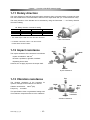
1-11 Rotary direction
The rotary direction of the RSF supermini series actuators when a forward rotation command is given
from the HA-680 driver is forward rotation seen from the output shaft side (i.e. counterclockwise: CW).
The rotary direction of the HA-680 can be switched by using the Parameter → “20: Rotary direction
command” setting.
“20: Rotary direction command” setting
Value
FWD command
REV command
Setting
0
1
FWD rotation
REV rotation
REV rotation
FWD rotation
Default
* The model shape is RSF-5A. RSF-3B is also the same.
FWD: CW rotation
* For details of the driver, refer to “AC Servo Driver
HA-680 Series Technical Data.”
Top
1-12 Impact resistance
Right
Back
The impact resistance of the actuators is as follows.
Impact acceleration: 300 m/s2
Direction: top/bottom, right/left, front/back
Repeating times: three
However, do not apply impact to the output shaft.
Left
Front
Bottom
Impact resistance
Top
1-13 Vibration resistance
The vibration resistance of the actuators for
up/down, left/right, and front/back is as follows.
Right
Vibration acceleration: 49m/s2 (5G)
Frequency: 10~400Hz
Left
Front
This specification does not guarantee fretting wear
of mechanism components due to micro vibrations.
Horizontal
installation
Bottom
Vibration resistance
RSF-Super_V1_02
- 10 -
Back
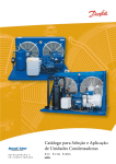
Chapter 1 Overview of the RSF supermini series
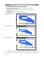
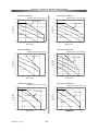
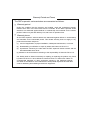
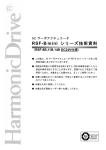
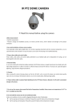
1-14 Torque-speed characteristics
The following graphs show the usable ranges of the RSF supermini series actuators.
• Acceleration and deceleration range:
The range allows instantaneous operation like acceleration and deceleration, usually.
• Continuous duty range:
The range allows continuous operation for the actuator.
• 50% duty range:
The range allows the 50% duty time operation of a cycle time.
■ RSF-3B-30-E020-C
放熱板:85×85×3[mm]
Radiation plate
80×85×3 (mm)
0.10
Torque
[Nm]
トルク[Nm]
0.08
加減速運転領域
Acc./dec. range
0.06
0.04
0.02
連続運転領域
Continuous
range
50% duty range
50%デューティ使用領域
0.00
0
50
100
150
200
回転速度[r/min]
Speed [r/min]
■ RSF-3B-50-E020-C
250
300
350
放熱板:85×85×3[mm]
Radiation plate
80×85×3 (mm)
0.20
Torque
[Nm]
トルク[Nm]
0.15
加減速運転領域
Acc./dec. range
0.10
0.05
Continuous
range
連続運転領域
50% duty range
50%デューティ使用領域
0.00
0
50
100
150
回転速度[r/min]
Speed [r/min]
200
250
■ RSF-3B-100-E020-C
放熱板:85×85×3[mm]
Radiation plate
80×85×3 (mm)
0.25
Torque
[Nm]
トルク[Nm]
0.20
加減速運転領域
Acc./dec.
range
0.15
0.10
0.05
Continuous
range
連続運転領域
50% duty range
50%デューティ使用領域
0.00
0
20
40
60
80
回転速度[r/min]
Speed [r/min]
100
120
Note:
The values of the graph are obtained when the aluminum radiation plate shown at the upper right of the
graph.
Note:
Even in the continuous range, if it is used continuously in one direction, please consult with us.
RSF-Super_V1_02
- 11 -
Chapter 1 Overview of the RSF supermini series
■ RSF-5A-30-E050-C, RSF-5A-30-E050-BC
Radiation plate
0.6
150×150×3 (mm)
Torque [Nm]
トルク[Nm]
0.5
Acc./dec. range
0.4
0.3
0.2
0.1
Continuous range
50% duty range
0.0
0
50
100
150
200
250
300
350
回転速度[r/min]
Speed [r/min]
■ RSF-5A-30-E050-C, RSF-5A-50-E050-BC
Radiation plate
1.0
150×150×3 (mm)
Torque [Nm]
トルク[Nm]
0.8
Acc./dec. range
0.6
0.4
0.2
Continuous range
50% duty range
0.0
0
50
100
150
200
250
Speed
[r/min]
回転速度[r/min]
■ RSF-5A-30-E050-C, RSF-5A-100-E050-BC
Radiation plate
1.5
150×150×3 (mm)
Torque [Nm]
トルク[Nm]
1.2
Acc./dec. range
0.9
0.6
0.3
Continuous range
50% duty range
0.0
0
20
40
60
80
100
120
回転速度[r/min]
Speed
[r/min]
Note:
Note:
The values of the graph are obtained when the aluminum radiation plate shown at the upper right of the
graph.
Even in the continuous range, if it is used continuously in one direction, please consult with us.
RSF-Super_V1_02
- 12 -
Chapter 1 Overview of the RSF supermini series
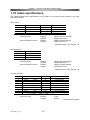
1-15 Cable specifications
The following tables show specifications of the cable for the motor and the encoder of the RSF
supermini actuators.
Motor cable
Pin No.
1
2
3
4
Color
Red
White
Black
Green
(RED)
(WHT)
(BLK)
(GRN)
Connector used
Recommended connector
Signal name
Remark
U
V
W
FG
Motor phase-U
Motor phase-V
Motor phase-W
Grounding
Housing:
Contact:
Housing:
Contact:
PALR-04VF (with retainer)
S(B)PAL-001T-P0.5
PARP-04V (with retainer)
S(B)PA-001T-P0.5
Manufactured by J.S.T. Mfg Co., Ltd
Brake lead wire
Pin No.
1
2
3
Line color
Blue
Yellow
Gray
(BLU)
(YEL)
(GRY)
Connector used
Recommended connector
Housing:
Contact:
Housing:
Contact:
PALR-03VF (with retainer)
S(B)PAL-001T-P0.5
PARP-03V (with retainer)
S(B)PA-001T-P0.5
Manufactured by J.S.T. Mfg Co., Ltd
Encoder lead wire
Pin No.
1
2
3
4
5
6
7
8
9
Color
White
Green
Yellow
Brown
Blue
Orange
Red
Black
Connector used
(WHT)
(GRN)
(YEL)
(BRW)
(BLU)
(ORG)
(RED)
(BLK)
Signal name
Remark
A
B
Z
U
V
W
+5V
GND
A phase output
B phase output
Z phase output
U phase output
V phase output
W phase output
Power supply input
Power supply input
Housing:
Terminal:
51021
50058
Manufactured by Molex
RSF-Super_V1_02
- 13 -
Chapter 2 Selection of the RSF supermini Series
Chapter 2 Selection of the RSF supermini Series
2-1 Allowable load moment of inertia
To make full use of high precision and high performance of the RSF supermini series actuator, perform
temporary selection by considering the load moment of inertia and rotation speed.
As a guideline, the load moment of inertia should be 3 to 5 times the moment of inertia of the actuator.
For the moment of inertia of the actuator, refer to “1-4 Specifications of RSF supermini actuators.”
Refer to appendix 1 for the calculation of moment inertia.
The rotation speed cannot exceed the maximum rotation speed of the actuator. For the maximum
rotation speed, refer to “1-4 Specifications of RSF supermini actuators.”
2-2 Variable load moment of inertia
RSF supermini series actuators include Harmonic Drive® gearing that has a high reduction ratio.
Because of this there are minimal effects of variable load moment of inertias to the servo drive system.
In comparison to direct servo systems this benefit will drive the load with a better servo response.
For example, assume that the load moment of inertia increases to N-times during its motion (for
example, robot arms). The effect of the variable load moment of inertia to the [total inertia converted
into motor shaft] is as follows:
The symbols in the formulas are:
JS:
JM:
total moment of inertia converted into
motor shaft
moment inertia of motor
R:
reduction ratio of RSF supermini series
◆
Ratio of load moment of inertia to motor inertia
N:
variation ratio of load moment of inertia
Direct drive
Before: JS=JM(1 + L )
◆
L:
After: JS'=JM(1 + NL )
Ratio: Js' /Js=
1 + NL
1+ L
Ratio: Js' /Js=
1 + NL / R 2
1 + L / R2
RSF supermini actuator drive
⎛
⎜
Before: JS=JM⎜⎜1 +
⎝
L ⎞⎟
⎟
R 2 ⎟⎠
⎛
⎜
After: JS'=JM⎜⎜1 +
⎝
NL ⎞⎟
⎟
R 2 ⎟⎠
In the case of the RSF supermini actuator drive, as the reduction ratio is [R=30], [R=50], or [R=100] and
the square of the reduction ratio [R2=900], [R2=2500], or [R2=10000] the denominator and the
numerator of the ratio are almost [1]. Then the ratio is [F≒1]. This means that drive systems are hardly
affected by the load moment of inertia variation. Therefore, it is not necessary to take the load moment
of inertia variation in consideration for selecting an RSF supermini actuator or for setting up the HA-680
driver.
2-3 Verifying loads
The RSF supermini series incorporates a precision 4-point contact ball bearing for direct support of
external load. To make full use of the performance of the RSF supermini series, check the maximum
load moment, life of the 4-point contact ball bearing, and static safety factor.
For detailed calculation methods for the maximum load moment, life of the 4-point contact ball bearing,
and static safety factor, refer to the “Harmonic Drive® CSF Mini series” catalogue.
RSF-super_V1_02
- 14 -
Chapter 2 Selection of the RSF supermini Series
2-4 Duty cycles
When a duty cycle includes many frequent start and stop operations, the actuator generates heat by big
starting and braking current. Therefore, it is necessary to study the duty cycle profile.
The study is as follows:
2-4-1
Actuator speed
Screw pitch (mm)
Calculate the required RSF supermini
actuator speed (r/min) to drive the load.
Speed (r/min)
45r/min
Liner speed (mm/min)
Rotary speed (r/min) = Pitch of screw(mm)
For linear motion, convert with the formula
below:
90r/min
100r/min
150r/min
Select a reduction ratio from [30], [50] and
[100] of an RSF supermini actuator of which
the maximum speed is more than the
required speed.
2-4-2
200r/min
333r/min
Linear speed (mm/min)
Load moment of inertia
Calculate the load moment of inertia driven by the RSF supermini series actuator.
Refer to appendix 1 for the calculation.
Tentatively select an RSF supermini actuator referring to section [2-1 allowable load moment of inertia]
with the calculated value.
2-4-3
Load torque
Calculate the load torque as follows:
◆
Rotary motion
The torque for the rotating mass [W] on the friction
ring of radius [r] as shown in the figure to the right.
Mass: W
Radius: r
T = 9.8 × μ × W × r
Friction:μ
T: torque (N・m)
μ: coefficient of friction
W: mass (kg)
r: radius of friction face (m)
The load torque is restricted by the allowable load of the actuator (refer to “1-10 Allowable load”) and
load moment of inertia as well as by the load driven by the actuator.
Examine them carefully before using the actuator.
RSF-super_V1_02
- 15 -
Chapter 2 Selection of the RSF supermini Series
◆
Horizontal linear motion
The following formula calculates the torque for horizontal linear motion of mass [W] fed by the screw of
pitch [P].
T = 9.8 × μ × W ×
P
2×π
T:
μ:
W:
P:
◆
Pitch: P
torque (N・m)
coefficient of friction
mass (kg)
screw pitch (m)
Mass: W
Friction: μ
Vertical linear motion
The following formula calculates the torque for vertical linear
motion of mass [W] fed by the screw of pitch [P].
T = 9.8 × W ×
P
2×π
Mass: W
Pitch: P
2-4-4
Acceleration time and deceleration time
Calculate acceleration and deceleration times for the selected actuator.
Acceleration: ta = (JA + JL ) ×
2×π
N
×
60
T M − TL
(1)
Deceleration: td = (JA + JL ) ×
2×π
N
×
60
TM + 2 × TF − TL
(2)
Ta:
Td:
JA :
JL :
N:
TM:
TL:
Speed
acceleration time (sec)
N
deceleration time (sec)
actuator inertia (kg・m2)
load moment of inertia (kg・m2)
Time
actuator speed (r/min)
ta
td
maximum torque of actuator (N・m)
load torque (N・m)
note that the polarity of the load torque is plus (+) for counter direction of revolution , and
minus (-) for same direction.
The friction torque of the actuator TF (N・m) can also be obtained from the following formula:
TF=KT×IM-TM
KT
IM
(3)
: Torque constant [N・m/A]
: Maximum current [A]
RSF-super_V1_02
- 16 -
Chapter 2 Selection of the RSF supermini Series
●
Example: 1
The load conditions are:
•
•
•
•
Rotary speed: 140r/min
Load moment of inertia: 0.9×10⁻³ kg・m2
Load torque is so small as to be negrected.
Acceleration/deceleration time is 0.03sec (30msec) or less.
(1) Compare these conditions with the “1-4 Specifications of RSF supermini actuators” and
temporarily select RSF-5A-50.
(2) Obtain JA=1.83×10⁻⁴kg・m2, TM =0.9 N・m, KT=0.54 N・m/A, and IM =2.2A from “1-4 Specifications of
RSF supermini actuators.”
(3) The friction torque of the actuator is TF = 0.54×2.2-0.9 = 0.29 N・m from Formula (3) on the
previous page.
(4) Therefore, the shortest acceleration time and deceleration time can be obtained from Formula (1)
and Formula (2), as follows:
ta = (0.183×10⁻³+0.9×10-3)×2×π/60×140/0.9 = 0.018 sec (18msec)
td = (0.183×10⁻³+0.9×10-3)×2×π/60×140/(0.9+2×0.29) = 0.011 s (11msec)
(5) Because the assumed acceleration/deceleration time is 0.03sec (30msec) or less, the temporarily
selected actuator can be used for acceleration/deceleration, based on the result of (4).
(6) If the calculation results of the acceleration/deceleration time do not fall within the desired time
range, examine them again as follows.
• Try to reduce the load moment of inertia.
• Re-examine the gear ratio and gear head model.
2-4-5
Calculating equivalent duty
The load conditions, which are torque, speed,
moment of inertia, acceleration/deceleration time,
loading time, are limited by the actuator to drive the
load. To select the proper actuator, the equivalent
duty of the load should be calculated.
N
The %ED (percent equivalent duty) is:
where, ta:
td:
tr:
t:
KLa:
KLr:
KLd:
ta
(4)
td
ts
Time
t: duty cycle
acceleration time in second
deceleration time in second
driving time in second
single cycle time in second
duty factor for acceleration time
duty factor for driving time
duty factor for deceleration time
RSF-super_V1_02
tr
- 17 -
Torque
KLa × ta + KLr × tr + KLd × td
%ED =
× 100
t
ts: stop time
Speed
Ta, Tr, Td: output torque
Td
Time
Chapter 2 Selection of the RSF supermini Series
◆
Example 2: getting duty factors of KLa, KLr and KLd
As a result of Calculation Example 1 shown below, the selected actuator RSF-5A-50 works fine, so
RSF-5A-50 can be used for duty factor graphs.
Operation conditions:
• The inertial load is accelecated at the maximum torque of the actuator, and decelerated at the
maximum torque after operation at a fixed speed.
• The movement angle θ of one cycle is 120°.
• The duration of one cycle is 0.4 (s).
• The other conditions are the same as Calculation Example 1.
(1) KLa and KLd: The average speed during the rotation speed change from 0 to 140r/min is 70r/min.
From the duty factor graphs, KLa=KLd≒1.5 can be obtained.
(2) KLr: Tr≒0 for the inertial load. Similarly, from the duty factor graphs, KLr≒0.29 can be read.
(3) The movement angle can be obtained from the area in the “Rotation speed-Time” diagram above.
In other words, the movement angle θ can be expressed as follows:
θ = (N / 60) x {tr + (ta + td) / 2} x 360
Solving the formula above for tr (operation time at a fixed speed of N), the following can be
obtained.
tr = θ/ (6 x N) – (ta + td) / 2
Substituting θ= 120° and ta= 0.03(s), td= 0.03(s), and N= 140r/min from Example 1, tr=0.113(s).
(4) Because the cycle time is 0.4(s), the %ED is obtained as follows:
%ED = (1.5x 0.03 + 0.29 x 0.113 + 1.5 x 0.03) / 0.4 x 100 = 30.7%
Because the value of %ED obtained is below 100, continuous repeated operation of this cycle can
be done.
If the %ED is exceeded 100%, correct the situation by:
• Changing the speed-time profile
• Reducing load moment of inertia
RSF-5A-50-E050-C
1.0
Radiation plate: 150×150×3[mm]
(1) KLa, KLd
1.5
0.8
Allowed range
Torque
[Nm]
トルク[Nm]
1
0.6
0.67
0.4
KL=0.33
(2) KLr
0.2
Estimation line for
KL=0.29
0.0
0
RSF-super_V1_02
50
- 18 -
70
140
100
150
回転速度[r/min]
Speed [r/min]
200
250
Chapter 2 Selection of the RSF supermini Series
Graphs of duty factor
RSF-3B-30-E020-C
Radiation plate: 85×85×3[mm]
0.1
Allowed range
運転可能領域
0.09
トルク [Nm]
Torque [Nm]
0.08
1.5
0.07
1.0
0.06
0.05
0.67
0.04
0.03
KL=0.33
0.02
0.01
0
0
50
100
150
200
Speed [r/min]
回転速度
[r/min]
RSF-3B-50-E020-C
350
運転可能領域
Allowed range
0.14
1.5
0.12
トルク [Nm]
300
Radiation plate: 85×85×3[mm]
0.16
Torque [Nm]
250
0.1
1.0
0.08
0.67
0.06
0.04
KL=0.33
0.02
0
0
50
100
150
200
250
Speed
[r/min]
回転速度
[r/min]
RSF-3B-100-E020-C
Radiation plate: 85×85×3[mm]
0.25
Allowed range
運転可能領域
トルク [Nm]
Torque [Nm]
0.2
0.15
0.67
0.1
KL=0.33
0.05
0
0
20
40
60
Speed
[r/min]
回転速度
[r/min]
RSF-super_V1_02
- 19 -
80
100
120
Chapter 2 Selection of the RSF supermini Series
RSF-5A-30-E050-C
RSF-5A-30-E050-BC
Radiation plate: 150×150×3[mm]
0.6
Radiation plate: 150×150×3[mm]
0.6
Allowed range
0.5
0.5
0.4
1
0.3
Torque
トルク[Nm]
[Nm]
Torque
[Nm]
トルク「Nm]
0.4
0.67
0.2
1.5
0.3
1
0.2
0.67
KL=0.33
KL=0.33
0.1
0.1
0.0
0.0
0
50
100
150
200
250
300
0
350
50
100
150
Speed
[r/min]
回転速度[r/min]
0.9
0.9
0.8
0.8
0.7
0.7
Torque
[Nm]
トルク[Nm]
1
0.6
0.5
0.67
0.4
0.3
KL=0.33
0.2
350
2
Allowed range
1.5
0.6
1
0.5
0.4
0.67
0.3
KL=0.33
0.2
0.1
0.1
0.0
0.0
0
50
100
150
200
0
250
50
100
150
200
250
Speed
[r/min]
回転速度[r/min]
回転速度[r/min]
Speed
[r/min]
RSF-5A-100-E050-C
RSF-5A-100-E050-BC
Radiation plate: 150×150×3[mm]
Radiation plate: 150×150×3[mm]
1.6
1.6
1.4
1.4
Allowed range
1.0
1.2
Torque
[Nm]
トルク[Nm]
1.2
Torque
[Nm]
トルク「Nm]
300
Radiation plate: 150×150×3[mm]
1.0
Allowed range
1.5
250
RSF-5A-50-E050-BC
Radiation plate: 150×150×3[mm]
1.0
200
Speed
[r/min]
回転速度[r/min]
RSF-5A-50-E050-C
Torque
[Nm]
トルク[Nm]
Allowed range
2
1.5
0.67
0.8
0.6
KL=0.33
Allowed range
1
1.0
0.8
0.67
0.6
0.4
0.4
0.2
0.2
KL=0.33
0.0
0.0
0
20
RSF-super_V1_02
40
60
Speed
[r/min]
回転速度[r/min]
80
100
120
0
20
40
60
Speed
[r/min]
回転速度[r/min]
- 20 -
80
100
120
Chapter 2 Selection of the RSF supermini Series
2-4-6
Effective torque and average speed
Addionally to the former studies, the effective torque and the average speed should be studied.
(1) The effective torque should be less than allowable continuous torque specified by the driver.
(2) The average speed should be less than allowable continuous speed of the actuator.
Calculate the effective torque and the average speed of an operating cycle as shown in “2-4-5
Calculating equivalent duty”.
Tm =
Ta 2 × (ta + td) + Tr 2 × tr
t
Nav =
N × ta + N × tr + N × td
2
2
t
Tm: effective torque (N・m)
Ta: maximum torque (N・m )
Tr: load torque (N・m)
ta: acceleration time (s)
td: deceleration time (s)
tr: running time at constant speed (s)
t:
time for one duty cycle (s)
Nav: average speed (r/min)
N: driving speed (r/min)
If the calculation results for the effective torque and average rotation speed are not within the range of
continuous usage in the graph shown in “1-14 Usable range,” take measures to reduce the duty.
◆
Example 3: getting effective torque and average speed
Effective torque and average speed are studied by using the operation conditions of Example 1 and 2.
1)
Effective torque
From the parameters of Ta = 8.3 N・m, Tr = 0 N・m, ta = 0.113 s, tr = td = 0.03 s, t=0.4 s,
Tm =
0.9 2 × (0.03 + 0.03)
= 0.349 N ⋅ m
0.4
The value exceeds the allowable continuous torque (0.29 N・m) of RSF-5A-50 temporarily selected in
Example 1, so continuous operation cannot be done using the cycle set in Example 2. The following
formula is the formula for effective torque solved for t. By substituting the value of allowable
continuous torque in Tm of this formula, the allowable value for one cycle time can be obtained.
t=
Ta 2 × (ta + td) + Tr 2 × tr
Tm 2
Substituting 0.9 N・m for Ta, 0 N・m for Tr , 0.349 N・m for Tm , 0.03 s for ta , 0.113 s for tr, and 0.03 s for
td :
t=
0.9 2 × (0.03 + 0.03 )
= 0.578 [s]
0.29 2
Namely, when the time for one duty cycle is set more than 0.578 s, the effective torque [Tm] becomes
less than 2.9 N・m, and the actuator can drive the load with lower torque than the continuous torque
continuously.
2)
Average speed
From the parameters of N = 140 r/min, ta = 0.03 s, tr = 0.113 s, td = 0.03 s, t = 0.4 s
Nav
140 × 0.03 + 140 × 0.113 + 140 × 0.03
2
2
=
= 34.64 [r/min]
0.578
As the speed is less than the continuous speed (90 r/min) of RSF-5A-50, it is possible to drive it
continuously on new duty cycle.
RSF-super_V1_02
- 21 -
Chapter 2 Selection of the RSF supermini Series
2-4-7
Permissible overloaded time
In case RSF supermini series is intermittently operated in allowable continuous torque or more, the
overloaded time is limited by the protective function in the driver even if the duty cycle is allowed. The
limits are shown in the figure below.
RSF-3B-50
Loaded time [s]
RSF-3B-100
RSF-3B-30
Torque [Nm]
RSF-5A-50
Loaded time [s]
RSF-5A-100
RSF-5A-30
Torque [Nm]
RSF-super_V1_02
- 22 -
Chapter 3 Installing the actuator
Chapter 3 Installing the actuator
3-1 Receiving Inspection
Check the following when products are received.
●
Inspection procedure
(1) Check the shipping container and item for any damage that may have been caused during
transportation. If the item is damaged, immediately report the damage to the dealer it was
purchased from.
(2) A label is attached on the right side of the RSF supermini series actuator. Confirm the products you
ordered by comparing with the model on the [TYPE] line of the label. If it is different, immediately
contact the dealer it was purchased from.
The model code is interpreted as follows:
RSF-5
A-50-E 050-C
RSF series actuator
Frame size
Design version
Reduction ratio of Harmonic drive® gearing
Encoder specifications
Number of pulses of the encoder
Specification
For details of model symbols, refer to “1-2 Models” on page 2.
(3) On the label of the HA-680 driver, the model code of the actuator to be driven is indicated on the
[ADJUSTED FOR USE WITH] line. Match the actuator with its driver so as not to confuse the item
with the other actuators.
Only connect the actuator specified on the driver label.
WARNING
The drivers have been tuned for the actuator specified on the driver label. Wrong
combination of drivers and actuators may cause low torque problems or over current
that may cause physical injury and fire.
(4) The HA-680 driver is for 24VDC supply voltage only.
24VDC cannot be used.
Any power supply voltage other than
Do not connect a supply voltage other than the voltage specified
on the label.
WARNING
The wrong power supply voltage (other than 24VDC) may damage the driver resulting
physical injury and fire.
RSF-super_V1_02
- 23 -
Chapter 3 Installing the actuator
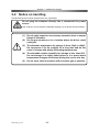
3-2 Notice on handling
Handle RSF supermini series actuators with care, specifically:
Do not plug the actuators directly into a commercial line power
source.
WARNING
This could burn out the actuator, potentially resulting in a fire and/or electrical hazard.
(1)
Do not apply impact or unnecessary excessive force to output
flange of actuators.
(2)
Do not put actuators on in a location where the driver could
easily fall.
(3)
The allowable temperature for storage is from -20°C to +60°C.
Do not expose it to the sunlight for a long time and do not
store it in areas with widely fluctuating temperatures.
(4)
The allowable relative humidity for storage is less than 80%.
Do not storage it in highly humid place or in a place where
temperature changes excessively during the course of a day.
(5)
Do not store units in locations with corrosive gas or particles.
CAUTION
RSF-super_V1_02
- 24 -
Chapter 3 Installing the actuator
3-3 Location and installation
3-3-1
Environment of location
The environmental conditions of the location for RSF supermini series actuators must be as follows.
Service temperature: 0°C to 40°C
When the actuator is installed in a closed space, the temperature in the
space may be higher than the atmosphere because of heat emission by the
actuator. Design the closed space size, ventilation system, and device
locations so the ambient temperature near the actuator is always less than
40°C.
Service humidity:
20 to 80% relative humidity, without condensation
Make sure no water condensation occurs at the place where there is a large
temperature change in a day or due to frequent heat-and-cool cycles due to
the operation of the actuator.
Vibration:
less than 49m/sec2 (10Hz~400Hz)
Impact:
less than 300 m/sec2
Make sure the actuator is in an area free from: dust, water condensation, metal powder, corrosive
gas, water, water drops, and oil mist.
Locate the driver indoors. Do not expose it to the sunlight.
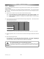
3-3-2
Considerations into External Noise
Pay sufficient attention when installing the actuator: The actuator may malfunction by external noise
depending on the conditions of installation.
Make sure that the FG line of RSF-5A is securely grounded.
Because RSF-3B does not have any FG line from the motor enclosure. Thus, when using it,
make sure that that enclosure is securely grounded to the body of the equipment through the gear
head house. In addition, make sure that the body of the equipment is securely grounded.
Do not bind the motor line and encoder signal line together.
Do not draw any external power line (i.e., driver power supply line, 100/200 VAC line.), actuator
signal line, and motor line through the same pipe or duct or bind them together.
The noise tolerance values of RSF supermini equipment are listed below.
They are guide values from a measurement that were performed using a standard relay cable in a
noise test environment while the clamp filter included with the product was installed to the equipment.
Note that the noise tolerance values in your actual environment of use may differ from them.
Model
Noise tolerance (encoder signal line)
RSF-super_V1_02
RSF-3B
1. 5k V
- 25 -
RSF-5A
2. 0 kV
Chapter 3 Installing the actuator
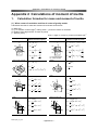
3-3-3
Installation
Since the RSF supermini series actuator is a high precision servo mechanism, great care is required for
proper installation.
Install the actuator taking care not to damage accurately machined surfaces. Do not hit the actuator
with a hammer. Take note that actuators provide a glass encoder, which may be damaged by impact.
●
Procedure
(1) Align the axis of rotation of the actuator and the load mechanism precisely.
Note 1: Very careful alignment is required especially when a rigid coupling is applied. Slight
differences between centerlines will cause failure of the output shaft of the actuator.
Note 2: When installing the actuator to a coupling, use a plastic hammer to avoid excessive
physical shocks.
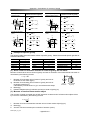
(2) Fasten the flange of the actuator with flat washers and high strength bolts. Use a torque wrench
when tightening the fasteners.
The recommended tightening torque is shown in the table below:
Model
Number of bolts
RSF-3B
4
Bolt size
M1.6
Installation PCD
Wrenching torque
Transfer torque
RSF-5A
2
M2
mm
15
25
N・m
0.26
0.25
kgf・cm
0.03
0.03
N・m
3.0
2.0
kgf・cm
0.2
0.2
Recommended bolt: JIS B 1176 bolt with hexagonal hole; Strength category: JIS B 1051 12.9 or greater
(3) For wiring operation, refer to “AC Servo Driver for 24VDC Power Supply HA-680 Series Technical
Data.”
(4) Motor cable and encoder cable
Do not pull the cable. Do not hang the actuator with the cable. If you do, the connection part
may be damaged. Install the cable with slack not to apply tension to the actuator. Especially, do
not use the actuator under any condition where the cable is bent repeatedly.
Do not disassemble and re-assemble the actuator.
CAUTION
RSF-super_V1_02
The Harmonic Drive Systems, Inc. does not guarantee the actuator that has been
reassembled by others than the authorized persons by the Harmonic Drive Systems,
Inc.
- 26 -
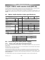
Chapter 4 Motor shaft retention brake
Chapter 4 Motor shaft retention brake(RSF-5A)
The RSF supermini series provides an actuator with a motor shaft retention brake as standard (Option
symbol: B), which can meet the fail-safe requirement without any additional brake.
The brake has 2 coils; one for releasing brake, and another for retaining the released state. By
controlling the currents through the coils, power consumption during retention of brake release can be
reduced.
4-1 Motor shaft retention brake specifications
Gear ratio
Item
Retention torque
Note 1
Moment of inertia
Note 1
50
100
V
Single disc dry type deenergisation operation type
(Separate attraction coil and retention coil)
24VDC±10%
A
0.8
A
0.05
Method
Brake operating voltage
Current consumption during release
(at 20°C)
Current consumption during retention
of release (at 20°C)
30
N・m
0.18
0.29
0.44
kgf・cm
1.84
2.96
4.49
(GD2/4)
2
kg・cm
0.111 10-3
0.309 10-3
1.234 10-3
1.132 10-3
3.151 10-3
12.58 10-3
(J)
kgf・cm・s2
g
Weight
Note 2
86.0
Number of allowable brake
Note 3
100,000 times
operations
Note 1: This is a value at the output shaft of the actuator.
Note 2: This is a value for the entire actuator.
Note 3: The motor shaft rotation speed is controlled as shown in the following table.
Gear ratio
Output shaft rotation speed
[r/min]
Motor shaft rotation speed
[r/min]
1:30
1:50
1:100
5.0
3.0
1.5
150
4-2 Controlling the brake power supply
4-2-1
Using a relay cable (Recommended method)
The optional relay cables for brakes (EWA-B -JST 03-TMC) incorporate a circuit that controls the
brake current.
You don’t have to control the brake current, so it is recommended to use the actuator with a brake in
combination with a relay cable for brakes.
If the relay cable for brakes is used, brake can be operated by turning on/off the brake power supply.
The power supply for the brake (that can output 24VDC±10%) shall be provided by the customer. Use
a power supply unit that can output the current during release as described in “4-1 Motor shaft retention
brake specifications.”
The supply duration of the current consumption during release is 0.5sec or less at 24VDC±10%.
RSF-super_V1_02
- 27 -
Chapter 4 Motor shaft retention brake
4-2-2
Not using a relay cable
If the optional relay cable for brakes (EWA-B -JST 03-TMC) is not used, the customer must control the
brake power supply to the brake release coil and release retention coil.
Supply the power upon brake release and during brake release retention, as shown below.
Lead wire color
Upon brake
release
During release
retention
During brake use
Gray/Yellow
Blue/Yellow
Gray/Yellow
Applied voltage
24VDC±10%
0VDC
Blue/Yellow
Gray/Yellow
Blue/Yellow
24VDC±10%
0VDC
Supply the power to the coils according to the following time chart.
Brake released
Brake release
Brake ON
Brake release retained
Brake release coil
Wiring: Gray/Yellow (GND)
Brake release retention coil
Wiring: Blue/Yellow (GND)
Control the power supply so that the duration in which the power is supplied to the brake release coil
(gray/yellow) is 100ms or less. The brake will not be released only by the power supply to the brake
release retention coil. To release the brake, also supply the power to the brake release coil.
The power supply to the brake must be controlled.
Warning
Control the power supply to the brake as described in “4-2 Controlling the brake power
supply.” If the current flows continuously to the attraction coil, the actuator burns due
to temperature rise, causing fire or electric shock.
Be careful not to exceed the number of allowable brake operations
(Refer to “4-1 Motor shaft retention brake specifications”).
Warning
RSF-super_V1_02
If the number is exceeded, the retention torque drops and it cannot be
used as a brake.
- 28 -
Chapter 5 Options
Chapter 5 Options
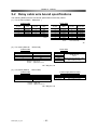
5-1 Relay cables
There are relay cables that connect the RSF supermini series actuator and driver.
There are 3 types of relay cables for encoders, motors, and brakes. Select an appropriate type
according to the model of the actuator you ordered.
●
Relay cable model (XX indicates the cable length 3m, 5m, or 10m.)
(1) For encoders
EWA-E××-M09-3M14
Cable length (03=3m, 05=5m, 10=10m)
Connector: 10114-3000VE
Cover:
10314-52F0-008
Mfg by 3M
Clamp filter
ZCAT2032-0930 (TDK)
Wafer right angle type
53048-0910
Mfg by Molex
Clamp filter
ZCAT2032-0930 (TDK)
(2) For motors
EWA-M××-JST04-TN2
Cable length (03=3m, 05=5m, 10=10m)
Shield
E Green/Yellow
Round crimp-style
terminal
1.25-4
W
Black
V
White
U
Red
Mfg by J.S.T. Mfg. Co., Ltd.
PARP-04V
Mfg by Omron
XW4B-06B1-H1
(3) For brakes
EWA-B××-JST03-TMC
Cable length (03=3m, 05=5m, 10=10m)
Application of 24VDC (non polar)
Mfg by J.S.T. Mfg. Co., Ltd.
PARP-03V
Round crimp-style
terminal
1.25-4
RSF-super_V1_02
- 29 -
Chapter 5 Options
5-2 Relay cable wire bound specifications
The following tables show the wire bound specifications of the relay cables.
(1) For encoders (EWA-E -M09-3M14 )
Actuator side
Pin NO.
1
2
3
4
5
Signal
name
A phase
B phase
Z phase
U phase
V phase
Driver side
Pin NO.
6
7
8
9
Signal
name
W phase
+5V
GND
N.C.
Connector: 53048-0910
Molex
(2) For motors (EWA-M
Pin NO.
1
2
3
4
5
6
7
-JST04-TN2)
Actuator side
Pin NO.
1
2
3
4
Connector
Signal
Pin NO.
Signal name
name
+5V
8
GND
B+ phase
9
U+ phase
Z+ phase
10
U- phase
B- phase
11
V+ phase
A+ phase
12
V- phase
Z- phase
13
W+ phase
A- phase
14
W- phase
Connector: 10114-3000VE
Cover:
10314-52F0-008
3M
Driver side
Signal name
U phase
V phase
W phase
FG
Housing: PARP-04V
Retainer: PMS-04V-S
Contact: S(B)PA-001T-P0.5
Signal name
U phase
V phase
W phase
FG
Shield
Connector
XW4B-06B1-H1
Omron
Round crimp-style terminal 1.25-4
With insulating coating
J.S.T. Mfg Co.,Ltd
(3) For brakes (EWA-B
-JST03-TMC)
Power supply side for brake
Actuator side
Pin NO.
1
2
3
Connector
Wire color
Red
White
Black
Retainer: PMS-03V-S
Housing: PARP-03V
Contact: S(B)PA-001T-P0.5
J.S.T. Mfg Co.,Ltd
RSF-super_V1_02
- 30 -
Wire color
Red, black
(nonpolar)
Connector
Round crimp-style terminal 1.25-4
With insulating coating
Chapter 5 Options
5-3 Connectors
There are 2 types of connectors for the driver for different set types:
●
Connector model: CNK-HA68-S1
For CN1, CN2, actuator line connection, power supply connection .........................4 types
●
Connector model: CNK-HA68-S2
For CN2, power supply connection...........................................................................2 types
Connector for CN1
Mfg by Sumitomo 3M
Connector type: 10114-3000VE
Case type: 10314-52F0-008
Connector for CN2
Mfg by Sumitomo 3M
Connector type: 10150-3000VE
Case type: 10350-52F0-008
Connector for power supply
Mfg by Phoenix Contact
Model: MC1.5/5 – ST – 3.81
Or
Mfg by Omron
Model: XW4B – 05B1 – H1
Connector for actuator connection
Mfg by Phoenix Contact
Model: MC1.5/6 – ST – 3.81
Or
Mfg by Omron
Model: XW4B – 06B1 – H1
RSF-super_V1_02
- 31 -
Appendix 1 Conversion of unit
Appendix 1 Conversion of unit
This technical manual basically uses the SI unit system. The conversion coefficients between the SI unit
system and other unit systems are shown below.
(1)
Length
SI unit
m
Unit
Coefficient
(2)
ft.
3.281
in.
39.37
Unit
Coefficient
m/s
m/min
60
ft./min
196.9
Unit
Coefficient
Unit
Coefficient
ft./s
3.281
in/s
39.37
m/s2
m/min2
3600
ft./min2
1.18x10⁴
m
m/min
ft./min
ft./s
0.0167 5.08x10⁻³ 0.3048
SI unit
in/s
0.0254
m/s
Unit
m/min2 ft./min2
ft./s2
-4
-5
Coefficient 2.78 x10 8.47x10
0.3048
ft./s2
3.281
in/s2
39.37
in/s2
0.0254
m/s2
SI unit
Force
SI unit
Unit
Coefficient
(5)
SI unit
in.
0.0254
Linear acceleration
SI unit
(4)
ft.
0.3048
Linear speed
SI unit
(3)
Unit
Coefficient
N
kgf
0.102
lb (force)
0.225
Unit
Coefficient
oz (force)
4.386
kgf
9.81
SI unit
lb (force)
4.45
oz (force)
0.278
N
Mass
SI unit
Unit
Coefficient
kg
lb.
2.205
Unit
Coefficient
oz.
35.27
SI unit
RSF-super_V1_02
-Appendix 1-1 –
lb.
0.4535
oz.
0.02835
kg
Appendix 1 Conversion of unit
(6)
Angle
SI unit
rad
Unit
Coefficient
(7)
Deg.
57.3
Min.
3.44x10³
Sec.
2.06x10⁵
Deg.
0.01755
Min.
2.93x10⁻⁴
SI unit
Sec.
4.88x10⁻⁶
rad
Angular speed
SI unit
rad/s
Unit
Coefficient
(8)
Unit
Coefficient
Deg./s
57.3
Deg./min
3.44x10³
Unit
Coefficient
r/s
0.1592
r/min
9.55
Deg./s
0.01755
Deg./min
2.93x10⁻⁴
SI unit
r/s
6.28
r/min
0.1047
rad/s
Angular acceleration
rad/s2
SI unit
Deg./s2
57.3
Unit
Coefficient
(9)
Deg./s2
0.01755
Unit
Coefficient
Deg./min2
3.44x10³
Deg./min2
2.93x10⁻⁴
rad/s2
SI unit
Torque
SI unit
Unit
Coefficient
Nm
kgfm
0.102
lbft
0.738
Unit
Coefficient
lbin
8.85
ozin
141.6
kgfm
9.81
SI unit
lbft
1.356
lbin
ozin
0.1130 7.06x10⁻³
Nm
(10) Moment of inertia
kgm2
SI unit
Unit
Coefficient
kgfms2
0.102
kgfcms2
10.2
lbft2
23.73
Unit
Coefficient
kgfms2
9.81
kgfcms2
0.0981
lbft2
0.0421
lbfts2
0.7376
lbin2
3.42x10³
lbins2
8.85
ozin2
5.47x10⁴
ozins2
141.6
lbfts2
1.356
lbin2
2.93x10⁻⁴
lbins2
0.113
ozin2
1.829x10⁻⁵
ozins2
7.06x10⁻³
kgm2
SI unit
(11) Torsional spring constant, moment of rigidity
SI unit
Nm/rad
Unit
Coefficient
kgfm/rad
0.102
kgfm/arc min
2.97 x10⁻⁵
kgfm/Deg.
1.78x10⁻³
lbft/Deg.
0.0129
lbin/Deg.
0.1546
Unit
Coefficient
kgfm/rad
9.81
Kgfm/arc min
3.37 x10⁴
kgfm/Deg.
562
lbft/Deg.
77.6
lbin/Deg.
6.47
SI unit
Nm/rad
RSF-super_V1_02
-Appendix 1-2 –
Appendix 2 Calculations of moment of inertia
Appendix 2 Calculations of moment of inertia
1.
Calculation formulas for mass and moment of inertia
(1) When center of revolution and line of center of gravity match
Calculation formulas for mass and moment of inertia are shown below.
m: Mass (kg)
Ix, Iy, Iz: moment of inertia (kgm2) making Axes x, y and z as centers of revolution
G: Distance from edge surface of center of gravity
ρ: Specific gravity
Units - Length: m, mass: kg, moment of inertia: kgm2
Mass, inertia,
position of center of gravity
Shape of object
Circular cylinder
Round pipe
m = π R2 L ρ
z
R
y
1
m R2
2
Iy =
1 ⎛⎜ 2 L2 ⎞⎟
m R +
3 ⎟⎠
4 ⎜⎝
Iz =
1 ⎛⎜ 2 L2 ⎞⎟
m R +
3 ⎟⎠
4 ⎜⎝
L
Tilted circular cylinder
R
R1
y
R2
Sphere
)
Iy =
L2 ⎫⎪
1 ⎧⎪ 2
m ⎨ R1 + R 22 +
⎬
4 ⎪⎩
3 ⎪⎭
Iz =
1 ⎧⎪ 2
L2 ⎫⎪
m ⎨ R1 + R 22 +
⎬
4 ⎪⎩
3 ⎪⎭
(
)
(
)
4
m = πR3 ρ
3
R
{ (
)
1
m R12 + R 22
2
L
R1: Outside diameter
R2: Inside diameter
(
Ix =
x
m = π R2 L ρ
1
Iθ =
m
12
θ
m = π ⎛⎜ R 1 2 + R 2 2 ⎞⎟ L ρ
⎝
⎠
z
Ix =
x
Mass, inertia,
position of center of gravity
Shape of object
I=
}
× 3R 2 1 + cos 2 θ + L2sin 2θ
2
m R2
5
L
Elliptic circular cylinder
B
z
x
m = π BC L ρ
Ix =
C
y
L
x
C
A
(
1
Iy =
m (C
12
Ix =
y
Iz =
z
x
G
L
y
Regular square pipe
)
)
1
m B2 + C2
12
(
3
m R2
10
3
Iy =
m 4R 2 + L2
80
Ix =
R
1 ⎛⎜ B2 L2 ⎞⎟
m
+
4 ⎜⎝ 4
3 ⎟⎠
m = A BC ρ
B z
π
m = πR2 L ρ
3
)
1 ⎛ C2 L2 ⎞⎟
Iy = m⎜
+
4 ⎜⎝ 4
3 ⎟⎠
Iz =
Prism
(
1
m B2 + C2
16
Cone
2
+ A2
1
m A 2 + B2
12
)
D
- Appendix 2-1 -
(
)
Iz =
3
m 4R 2 + L2
80
G=
L
4
y
{
{
{
}
1
m (B - D)2 + D2
3
1
Iy = m A 2 + (B - D)2 + D2
6
1
Iz = m A 2 + (B - D )2 + D2
6
Ix =
x
RSF-super_V1_02
)
m = 4AD(B - D )ρ
B z
A
(
}
}
Appendix 2 Calculations of moment of inertia
Mass, inertia,
position of center of gravity
Shape of object
Rhombic prism
B
Regular he xagon prism
m=
z
x
C
y
A
z
G
C
x
y
A
z
B√ 3
)
x
B
1
m B 2 + 2A 2
24
Right-angled triangular
prism
1
ABC ρ
2
1
B2 2 2
+ C
Ix =
m
12
2
3
G=
2
2
y
A
m=
(
1
Iy =
m A
12 (
1
Iz =
m A
12 (
3 3
AB 2 ρ
2
5
Ix =
m B2
12
1
5
Iy =
m A 2 + B2
12
2
m=
)
(
(
Iz =
Equilateral triangular
prism
B
1
ABC ρ
2
1
Ix =
m B2 + C2
24
1
Iy =
m C 2 + 2A 2
24
Mass, inertia,
position of center of gravity
Shape of object
G1
2
x
C
2
B
C
3
G2
A
2
)
5
+ B )
2
2
1
ABC ρ
2
1
Ix =
m B2 + C2
36
1
2
Iy =
m A 2 + C2
12
3
m=
)
(
z
)
2
+ C )
3
B
+
2 )
(
1
Iz =
m A
12 (
y
(
1
Iz =
m (A
12
G1 =
C
3
2 2
B
3
B
G2 =
3
2
+
)
)
Example of specific gravity
The following table shows informative values of specific gravity. Please check actual specific gravities of
materials individually.
Material
SS45C
SS41C
Cast steel
Cast iron
Copper
Specific gravity
7.86
7.85
7.85
7.19
8.92
Material
Brass
Aluminum
Duralumin
Teflon
Fluorine resin
Specific gravity
8.5
2.7
2.8
2.2
2.2
Material
Epoxy resin
ABS
Silicone resin
Urethane rubber
Chloroprene rubber
Specific gravity
1.9
1.1
1.8
1.25
1.15
(2) When center of revolution and line of center of gravity do not match
Moment of inertia when axis of center of gravity and axis of revolution of an inertia field do not match is
calculated by the following formula.
F
I = Ig + mF 2
I:
Ig:
m:
F:
Moment of inertia when axis of center of gravity and axis of
revolution do not match (kgm2)
Moment of inertia when axis of center of gravity and axis of
revolution match (kgm2)
Calculated by formula shown in (1) in accordance with shape.
Mass (kg)
Distance between axis of revolution and axis of center of gravity (m)
Axis of
revolution
Axis of center
of gravity
(3) Moment of inertia of linear motion object
The moment of inertia converted into an RSF-supermini actuator axis of a linear motion object driven
by a screw is calculated by the following formula.
I =m
I:
m:
P:
(2Pπ )
2
Moment of inertia converted into actuator axis of a linear motion object (kgm2)
Mass (kg)
Amount of linear movement per revolution of actuator (m/rev)
RSF-super_V1_02
- Appendix 2-2 -
Appendix 2 Calculations of moment of inertia
2.
Moment of inertia of circular cylinder
Approximate values of moment of
inertia of circular cylinder can be
calculated from the graph on the
right.
2
Moment of inertia (kgm )
Length (mm)
1000
Moment of inertia (Specific gravity 2.7)
1000
100
100
Radius
10
10
Length
1
1
0.1
The top graph is applied to
aluminum (specific gravity 2.7) and
the bottom graph, to steel (specific
gravity 7.85).
0.01
0.001
10
-4
10
-5
10
-6
10
20
30
50
70 100
200
300
500 700 1000
Radius R(mm)
2
(Example)
Material: Aluminum
Outside diameter: 100mm
Length: 7mm
Shape: Circular cylinder
Outside diameter: 100mm
Since the outside diameter is
100mm, the radius is 50mm.
Based on the top graph, moment of
2
inertia is about 1.9 x 10⁻⁴ kgm .
Moment of inertia (kgm )
1000
Length (mm)
Moment of inertia (Specific gravity 7.85)
1000
100
100
10
10
1
1
0.1
(Calculated value: 0.000186kgm2)
0.01
0.001
10
-4
10
-5
10
-6
10
20
30
50
70 100
Radius R (mm)
RSF-super_V1_02
- Appendix 2-3 -
200
300
500 700 1000
Warranty Period and Terms
The RSF supermini series actuators are warranted as follows:
•
Warranty period
Under the condition that the actuator are handled, used and maintained properly
followed each item of the documents and the manuals, all the RSF supermini series
actuators are warranted against defects in workmanship and materials for the shorter
period of either one year after delivery or 2,000 hours of operation time.
•
Warranty terms
All the RSF supermini series actuators are warranted against defects in workmanship
and materials for the warranted period. This limited warranty does not apply to any
product that has been subject to:
(1) user's misapplication, improper installation, inadequate maintenance, or misuse.
(2) disassembling, modification or repair by others than Harmonic Drive LLC.
(3) imperfection caused by the other than the RSF supermini series actuator and the
HA-655/675/680 servo driver.
(4) disaster or others that does not belong to the responsibility of Harmonic Drive LLC.
Our liability shall be limited exclusively to repairing or replacing the product only found
by Harmonic Drive LLC to be defective. Harmonic Drive LLC shall not be liable for
consequential damages of other equipment caused by the defective products,
and shall not be liable for the incidental and consequential expenses and the labor
costs for detaching and installing to the driven equipment.
Harmonic Drive LLC
Boston
247 Lynnfield Street
Peabody, MA 01960
800-921-3332
F: 978-532-9406
www.HarmonicDrive.net
Worldwide Locations:
Harmonic Drive Systems, Inc.
Minamiohi 6-25-3, Shinagawa-ku
Tokyo 140, Japan
Harmonic Drive AG
Hoenbergstr, 14
Limburg/Lahn, D-65555 Germany
RSF manual rev_01-08