1
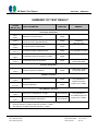
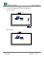
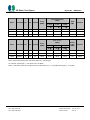
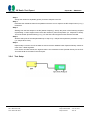
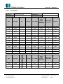
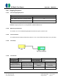
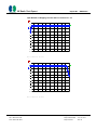
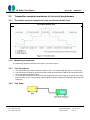
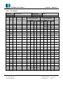
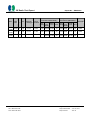
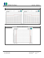
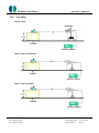
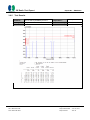
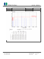
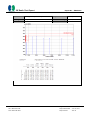
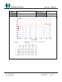
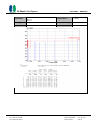
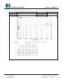
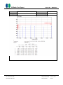
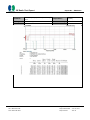
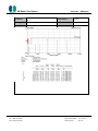
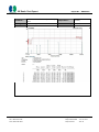
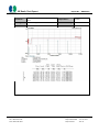
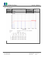
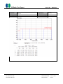
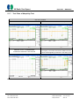
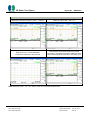
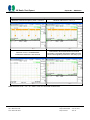
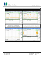
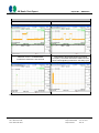
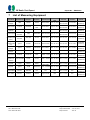
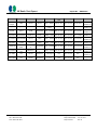
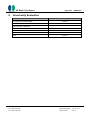
CE Radio Test Report
Report No. : ER3N2752
CE Radio Test Report
APPLICANT
: Texas Instruments Incorporated
EQUIPMENT
: WiFi and Bluetooth Evaluation Board
BRAND NAME
: Texas Instruments
MODEL NAME
: WL1835MODCOM8B
STANDARD
: ETSI EN 300 328 V1.8.1 (2012-06)
TEST DATE(S)
: Dec. 04, 2013 ~ Jan. 06, 2014
The measurements shown in this test report were made in accordance with the
procedures given in EUROPEAN COUNCIL DIRECTIVE 1999/5/EC and found to
be in compliance with ETSI Standard EN 300 328 V1.8.1 (2012-06).
The test results in this report apply exclusively to the tested model / sample.
Without written approval of SPORTON INTERNATIONAL INC., the test report
shall not be reproduced except in full.
Reviewed by: Joseph Lin / Supervisor
Approved by: Jones Tsai / Manager
SPORTON INTERNATIONAL INC.
st
No. 52, Hwa Ya 1 Rd., Hwa Ya Technology Park, Kwei-Shan Hsiang, Tao Yuan Hsien, Taiwan, R.O.C.
SPORTON INTERNATIONAL INC.
Page Number
: 1 of 69
TEL : 886-3-327-3456
Report Issued Date
: Jan. 20, 2014
FAX : 886-3-328-4978
Report Version
: Rev. 01
CE Radio Test Report
Report No. : ER3N2752
TABLE OF CONTENTS
REVISION HISTORY.......................................................................................................................................... 3
SUMMARY OF TEST RESULT ......................................................................................................................... 4
1
2
3
4
GENERAL DESCRIPTION .......................................................................................................................... 5
1.1
Applicant ............................................................................................................................................ 5
1.2
Manufacturer ...................................................................................................................................... 5
1.3
Feature of Equipment Under Test ..................................................................................................... 5
1.4
Details of Tested Sample (EUT) Information ..................................................................................... 6
1.5
Modification of EUT ........................................................................................................................... 6
1.6
Testing Facility ................................................................................................................................... 7
1.7
Applied Standards ............................................................................................................................. 7
1.8
Test Condition .................................................................................................................................... 7
TEST CONFIGURATION OF EQUIPMENT UNDER TEST ........................................................................ 8
2.1
Descriptions of Test Mode ................................................................................................................. 8
2.2
Connection Diagram of EUT Test Configurations ........................................................................... 11
2.3
Supported Unit used in test configuration and system .................................................................... 12
2.4
EUT Operation Test Setup .............................................................................................................. 12
TRANSMITTER PARAMETERS ............................................................................................................... 13
3.1
Maximum Transmit Power ............................................................................................................... 13
3.2
Maximum Equivalent Isotropically Radiated Power (E.I.R.P.) Spectral Density ............................. 17
3.3
Occupied Channel Bandwidth ......................................................................................................... 20
3.4
Frequency Hopping Requirements .................................................................................................. 23
3.5
Transmitter unwanted emissions in the out-of-band domain .......................................................... 31
3.6
Transmitter spurious emissions ....................................................................................................... 35
RECEIVER PARAMETERS ....................................................................................................................... 49
4.1
5
Receiver spurious emissions ........................................................................................................... 49
ADAPTIVITY TEST .................................................................................................................................... 53
5.1
Adaptivity and Receiver Blocking .................................................................................................... 53
6
PHOTOGRAPHS OF RADIATED EMISSION TEST CONFIGURATION ................................................. 65
7
LIST OF MEASURING EQUIPMENT ........................................................................................................ 67
8
UNCERTAINTY EVALUATION ................................................................................................................. 69
SPORTON INTERNATIONAL INC.
Page Number
: 2 of 69
TEL : 886-3-327-3456
Report Issued Date
: Jan. 20, 2014
FAX : 886-3-328-4978
Report Version
: Rev. 01
CE Radio Test Report
Report No. : ER3N2752
REVISION HISTORY
REPORT NO. VERSION
ER3N2752
Rev. 01
DESCRIPTION
ISSUED DATE
Initial issue of report
Jan. 20, 2014
SPORTON INTERNATIONAL INC.
Page Number
: 3 of 69
TEL : 886-3-327-3456
Report Issued Date
: Jan. 20, 2014
FAX : 886-3-328-4978
Report Version
: Rev. 01
CE Radio Test Report
Report No. : ER3N2752
SUMMARY OF TEST RESULT
CLAUSE
(EN 300 328)
TEST PARAMETER
PASS/FAIL
REMARK
PASS
-
PASS
Only applicable for
modulations
other than FHSS
Occupied Channel Bandwidth
PASS
-
Frequency Hopping Requirements
PASS
Only applicable for FHSS
Transmitter spurious emissions in OOB
PASS
-
Transmitter spurious emissions
PASS
Under limit 0.97 dB
at 4944.000 MHz
PASS
Under limit 6.19 dB
at 1970.000 MHz
Transmitter Parameters
4.3.1.1
4.3.2.1
4.3.2.2
4.3.1.7
4.3.2.6
4.3.1.3
4.3.1.4
4.3.1.8
4.3.2.7
4.3.1.9
4.3.2.8
Maximum Transmit Power
Maximum Equivalent Isotropically Radiated
Power (E.I.R.P.) Spectral Density
Receiver Parameters
4.3.1.10
4.3.2.9
Receiver spurious emissions
Adaptive Test Item
4.3.1.6
4.3.2.5
4.3.1.11
4.3.2.10
Adaptivity
PASS
Only applicable for
adaptive equipment
Receiver Blocking
PASS
Output Power >10dBm
Duty cycle, Tx-Sequence, Tx-gap
Not Required
Only applicable for
non-adaptive equipment
Medium Utilisation (MU) factor
Not Required
Output Power >10dBm
Non-Adaptive Test Item
4.3.1.2
4.3.2.3
4.3.1.5
4.3.2.4
Note:
1.
Bluetooth belongs to adaptive equipment and EIRP > 10dBm.
2.
WiFi belongs to adaptive equipment and EIRP > 10dBm.
SPORTON INTERNATIONAL INC.
Page Number
: 4 of 69
TEL : 886-3-327-3456
Report Issued Date
: Jan. 20, 2014
FAX : 886-3-328-4978
Report Version
: Rev. 01
CE Radio Test Report
1
1.1
Report No. : ER3N2752
General Description
Applicant
Texas Instruments Incorporated
12500 TI Boulevard M/S 8751. Dallas, TX 75243.
1.2
Manufacturer
Jorjin Technologies Inc.
17F, No. 239, Sec. 1, Datong Rd, Xizhi Dist. New Taipei City 221, Taiwan. R.O.C.
1.3
Feature of Equipment Under Test
The Equipment Under Test (hereafter called: EUT) is WiFi and Bluetooth Evaluation Board supporting,
Wi-Fi 2.4GHz 802.11b/g/n and Bluetooth features, and below is details of information.
General Information of Equipment Under Test
Equipment
Brand Name
WiFi and Bluetooth Evaluation Board
Texas Instruments
Model Name
Wi-Fi Specification
WL1835MODCOM8B
802.11b/g/n (HT20/HT40)
Bluetooth Version
v3.0 + EDR / v4.0 - LE
Power Supply
From test jig
Remark: The above EUT's information was declared by manufacturer. Please refer to the specifications
or user's manual for more detailed description.
SPORTON INTERNATIONAL INC.
Page Number
: 5 of 69
TEL : 886-3-327-3456
Report Issued Date
: Jan. 20, 2014
FAX : 886-3-328-4978
Report Version
: Rev. 01
CE Radio Test Report
1.4
Report No. : ER3N2752
Details of Tested Sample (EUT) Information
Product Specification subjective to this Test Standard
Transmitter / Receiver Frequency Range 2400 MHz ~ 2483.5 MHz
WLAN : 13
Number of Channels
Bluetooth : 79
Bluetooth 4.0 – LE: 40
WLAN : 5 MHz
Channel Spacing
Bluetooth : 1 MHz
Bluetooth 4.0 – LE: 2 MHz
<Ant. 1>
802.11b : 17.74 dBm
802.11g : 17.34 dBm
802.11n HT20 : 16.64 dBm
Maximum EIRP Average Power
802.11n HT40 : 15.24 dBm
Bluetooth BR (1Mbps) : 11.84 dBm
Bluetooth 4.0 - LE (1Mbps) : 10.44 dBm
MIMO <Ant. 1+2>
802.11n HT20 : 18.14 dBm
Antenna 1: Chip Antenna / -0.36 dBi
WLAN:
Antenna 2: Chip Antenna / 1.22 dBi
Antenna Type / Gain
Bluetooth :
Antenna 1: Chip Antenna / -0.36 dBi
Bluetooth 3.0 BR (1Mbps) : GFSK
Bluetooth 3.0 EDR (2Mbps) :π/4-DQPSK
Bluetooth 3.0 EDR (3Mbps) : 8-DPSK
Type of Modulation
Bluetooth 4.0 - LE : GFSK
802.11b : DSSS (DBPSK / DQPSK / CCK)
802.11g/n: OFDM (BPSK / QPSK / 16QAM / 64QAM)
Antenna Function for Transmitter
EUT Stage
Bluetooth v3.0
Bluetooth v4.0
802.11 b
802.11 g
802.11 n HT20
SISO
802.11 n HT20
MIMO
802.11 n HT40
Ant. 1
V
V
V
V
Ant. 2
-
V
-
V
V
V
-
Production Unit
Note: For other wireless features of this EUT, test report will be issued separately.
1.5 Modification of EUT
No modifications are made to the EUT during all test items.
SPORTON INTERNATIONAL INC.
Page Number
: 6 of 69
TEL : 886-3-327-3456
Report Issued Date
: Jan. 20, 2014
FAX : 886-3-328-4978
Report Version
: Rev. 01
CE Radio Test Report
1.6
Report No. : ER3N2752
Testing Facility
Test Site
SPORTON INTERNATIONAL INC.
Test Site Location
No. 52, Hwa Ya 1 Rd., Hwa Ya Technology Park,
Kwei-Shan Hsiang, Tao Yuan Hsien, Taiwan, R.O.C.
TEL: +886-3-327-3456
FAX: +886-3-328-4978
Test Site No.
Sporton Site No. :
st
05CH02-HY ; 05CH01-HY ; TH02-HY
1.7
Applied Standards
According to the specifications of the manufacturer, the EUT must comply with the requirements of ETSI
EN 300 328 V1.8.1 (2012-06).
Note: All test items were verified and recorded according to the standards and without any deviation
during the test.
1.8
Test Condition
Normal Voltage
DC 3.7V
Normal Temperature
25℃
Extreme Temperature
-30℃ and 70℃
Note: The test temperature was between -30°C ~ 70°C by manufacturer requested.
SPORTON INTERNATIONAL INC.
Page Number
: 7 of 69
TEL : 886-3-327-3456
Report Issued Date
: Jan. 20, 2014
FAX : 886-3-328-4978
Report Version
: Rev. 01
CE Radio Test Report
2
Report No. : ER3N2752
Test Configuration of Equipment under Test
2.1
Descriptions of Test Mode
a.
Preliminary tests were performed in different data rate and recorded the RF power output in the
following tables:
<Ant. 1>
Average Bluetooth RF Output Power (dBm)
Data rate
1Mbps
2Mbps
3Mbps
Avg. Power
12.10
7.60
7.60
Note:
Data rate Bluetooth 1Mbps was chosen to be tested due to the highest RF output power.
Average Bluetooth 4.0 - LE RF Output Power (dBm)
Data Rate
CH 00
CH 19
CH 39
Avg. Power
10.30
10.30
9.90
2.4GHz 802.11b RF Output Power (dBm)
Data rate
1Mbps
2Mbps
5.5Mbps
11Mbps
Avg. Power
16.20
16.10
16.10
16.10
2.4GHz 802.11g RF Output Power (dBm)
Data rate
6Mbps
Avg. Power
16.30
9Mbps 12Mbps 18Mbps 24Mbps 36Mbps 48Mbps 54Mbps
16.20
16.20
16.20
15.30
14.50
13.90
13.20
2.4GHz 802.11n HT40 RF Output Power (dBm)
Data rate
MCS0
MCS1
MCS2
MCS3
MCS4
MCS5
MCS6
MCS7
Avg. Power
13.90
13.80
13.80
13.80
13.80
13.80
12.80
11.50
SISO <Ant. 1>
2.4GHz 802.11n HT20 RF Output Power (dBm)
Data rate
MCS0
MCS1
MCS2
MCS3
MCS4
MCS5
MCS6
MCS7
Avg. Power
15.30
15.20
15.20
15.20
14.60
14.00
13.40
12.30
SPORTON INTERNATIONAL INC.
Page Number
: 8 of 69
TEL : 886-3-327-3456
Report Issued Date
: Jan. 20, 2014
FAX : 886-3-328-4978
Report Version
: Rev. 01
CE Radio Test Report
Report No. : ER3N2752
MIMO <Ant. 1+2>
2.4GHz 802.11n HT20 RF Output Power (dBm)
Data rate
Avg. Power
MCS8
MCS9
18.00
17.90
MCS10 MCS11 MCS12 MCS13 MCS14 MCS15
17.90
17.90
17.60
17.10
13.40
12.60
Note:
The data rates of WLAN 802.11b/g/n were set in 1Mbps for 802.11b (Ant. 1), 6Mbps for 802.11g
(Ant. 1), MCS0 for 802.11n HT20 (Ant. 1), MCS8 for 802.11n HT20 (Ant. 1+2), MCS0 for 802.11n
HT40 (Ant. 1) with both antennas transmit due to the highest RF output power for rest of test
items.
b.
During radiated spurious emissions testing, the interface cables and equipment positions were varied
according to European Standard EN 300 328 V1.8.1 (2012-06), and the frequency range of radiation
was investigated from 25 MHz to 12750 MHz.
SPORTON INTERNATIONAL INC.
Page Number
: 9 of 69
TEL : 886-3-327-3456
Report Issued Date
: Jan. 20, 2014
FAX : 886-3-328-4978
Report Version
: Rev. 01
CE Radio Test Report
Report No. : ER3N2752
Pre-scanned tests were conducted to determine the final configuration from all possible combinations. The
following tables are showing the test modes as the worst cases and recorded in this report.
Test Modes
RF
Tx
Rx
802.11b
802.11g
DSSS
OFDM
802.11b CH01 (2412MHz) for Ant. 1
802.11g CH01 (2412MHz) for Ant. 1
802.11b CH13 (2472MHz) for Ant. 1
802.11g CH13 (2472MHz) for Ant. 1
802.11b CH13 (2472MHz) for Ant. 1
-
Test Modes
RF
802.11n HT20
802.11n HT40
OFDM
OFDM
802.11n HT20 CH01 (2412MHz) for MIMO <Ant. 1+2>
Tx
802.11n HT20 CH13 (2472MHz) for MIMO <Ant. 1+2>
802.11n HT20 CH01 (2412MHz) for SISO <Ant. 1>
Rx
802.11n HT40 CH03 (2422MHz) for Ant. 1
802.11n HT40 CH11 (2462MHz) for Ant. 1
802.11n HT20 CH01 (2412MHz) for SISO <Ant. 1>
-
Test Modes
Bluetooth (1Mbps)
RF
Tx
Rx
GFSK
Bluetooth 4.0 - LE
GFSK
Bluetooth (1Mbps) CH00 (2402MHz) for Ant. 1
Bluetooth 4.0 - LE CH00 (2402MHz) for Ant. 1
Bluetooth (1Mbps) CH78 (2480MHz) for Ant. 1
Bluetooth 4.0 - LE CH39 (2480MHz) for Ant. 1
Bluetooth (1Mbps) CH00 (2402MHz) for Ant. 1
Bluetooth 4.0 - LE CH00 (2402MHz) for Ant. 1
Remark: All test modes of the Transmitter Radiated Spurious Emission (RSE) and Receiver Radiated Spurious
Emission (RSE) were tested; only the test worse data in bold of these modes were reported.
SPORTON INTERNATIONAL INC.
Page Number
: 10 of 69
TEL : 886-3-327-3456
Report Issued Date
: Jan. 20, 2014
FAX : 886-3-328-4978
Report Version
: Rev. 01
CE Radio Test Report
2.2
Report No. : ER3N2752
Connection Diagram of EUT Test Configurations
<Bluetooth Tx/Rx Mode>
Adapter
230 Vac / 50 Hz
Dipole Antenna
Notebook
EUT
Fixture
Bluetooth
Base Station
<WLAN Tx/Rx Mode>
Adapter
230 Vac / 50 Hz
Notebook
EUT
Fixture
SPORTON INTERNATIONAL INC.
Page Number
: 11 of 69
TEL : 886-3-327-3456
Report Issued Date
: Jan. 20, 2014
FAX : 886-3-328-4978
Report Version
: Rev. 01
CE Radio Test Report
2.3
Report No. : ER3N2752
Supported Unit used in test configuration and system
Item Equipment
Trade Name Model Name FCC ID Data Cable Power Cord
AC I/P:
1.
Notebook
DELL
P20G
FCC DoC N/A
Unshielded, 1.2 m
DC O/P:
Shielded, 1.8 m
AC I/P:
2.
Notebook
Lenovo
G480
N/A
N/A
Unshielded, 1.2 m
DC O/P:
Shielded, 1.8 m
2.4
3.
Bluetooth Base Station R&S
CBT32
N/A
N/A
Unshielded, 1.8 m
4.
Fixture
N/A
WG7XXXT01
N/A
N/A
N/A
5.
Adapter
Aviv Energy
HK-IP15-A05
N/A
N/A
Unshielded, 1.8 m
EUT Operation Test Setup
For Bluetooth test items, a programmed RF utility, “HCT Tester” was installed in notebook which was
programmed in order to make the EUT get into the engineering modes to contact with Bluetooth base
station for continuous transmitting and receiving signals.
For WLAN and Bluetooth 4.0 – LE test items, programmed RF utility, “HCT Tester” installed in the
notebook make the EUT provides functions like channel selection and power level for continuous
transmitting and receiving signals.
SPORTON INTERNATIONAL INC.
Page Number
: 12 of 69
TEL : 886-3-327-3456
Report Issued Date
: Jan. 20, 2014
FAX : 886-3-328-4978
Report Version
: Rev. 01
CE Radio Test Report
3
Report No. : ER3N2752
Transmitter Parameters
3.1
Maximum Transmit Power
3.1.1
Limit of Effective Isotropic Radiated Power
SUBCLAUSE 4.3.1.1.2 and 4.3.2.1.2
TEST CONDITION
Normal and Extreme Temperature Conditions
3.1.2
LIMIT
20dBm (e.i.r.p)
Measuring Instruments
The measuring equipment is listed in the section 7 of this test report.
3.1.3
Test Procedure
1.
The measurement procedure follows the clause 5.3.2.2.1 of the ETSI EN 300 328 V1.8.1 (2012-06).
2.
Placing the EUT in thermal chamber.
3.
The EUT is connected to external power supply.
4.
Setting thermal chamber temperature and power supply voltage at suitable values.
5.
The EIRP = A+G+Y, where A is the power measured, G is the assembly gain of the individual antenna
of the EUT in dBi and Y is the additional beamforming gain of the EUT in dB if applicable, here, Y=0.
3.1.4
Test Setup
Power Cable connect to
dummy battery
EUT
Power Meter
DC Power supply
Thermal Chamber
SPORTON INTERNATIONAL INC.
Page Number
: 13 of 69
TEL : 886-3-327-3456
Report Issued Date
: Jan. 20, 2014
FAX : 886-3-328-4978
Report Version
: Rev. 01
CE Radio Test Report
3.1.5
Report No. : ER3N2752
Test Results
Test Item :
Temperature :
EIRP Power
Test Engineer : Alex Lee
Mod.
Data Rate
24~26℃
Relative Humidity : 51~54%
NTX
Channel
Freq.
(MHz)
Conducted Power
(dBm)
T nom
T min
T max
25 ℃
-30 ℃
70 ℃
Gain
(dBi)
Pass/Fail
11b
1Mbps
1
1
2412
15.80
18.10
16.50
-0.36
Pass
11b
1Mbps
1
7
2442
16.20
17.60
16.80
-0.36
Pass
11b
1Mbps
1
13
2472
15.90
17.90
17.00
-0.36
Pass
11g
6Mbps
1
1
2412
13.60
14.90
13.90
-0.36
Pass
11g
6Mbps
1
7
2442
16.30
17.70
16.80
-0.36
Pass
11g
6Mbps
1
13
2472
13.10
15.10
14.10
-0.36
Pass
HT20
MCS0
1
1
2412
13.60
15.00
14.10
-0.36
Pass
HT20
MCS0
1
7
2442
15.30
17.00
16.00
-0.36
Pass
HT20
MCS0
1
13
2472
13.30
15.10
14.10
-0.36
Pass
HT40
MCS0
1
3
2422
11.50
13.00
12.00
-0.36
Pass
HT40
MCS0
1
7
2442
13.70
15.50
14.50
-0.36
Pass
HT40
MCS0
1
11
2462
13.90
15.60
14.50
-0.36
Pass
BT2.0
1Mbps
1
0
2402
12.10
12.20
11.70
-0.36
Pass
BT2.0
1Mbps
1
39
2441
12.00
11.90
11.50
-0.36
Pass
BT2.0
1Mbps
1
78
2480
12.10
11.80
11.30
-0.36
Pass
BT4.0
1Mbps
1
0
2402
10.30
10.80
10.20
-0.36
Pass
BT4.0
1Mbps
1
19
2440
10.30
10.70
10.20
-0.36
Pass
BT4.0
1Mbps
1
39
2480
9.90
10.30
9.90
-0.36
Pass
SPORTON INTERNATIONAL INC.
Page Number
: 14 of 69
TEL : 886-3-327-3456
Report Issued Date
: Jan. 20, 2014
FAX : 886-3-328-4978
Report Version
: Rev. 01
CE Radio Test Report
Mod.
Data Rate
NTX
Channel
Report No. : ER3N2752
Freq.
(MHz)
EIRP Power
(dBm)
T nom
T min
T max
25 ℃
-30 ℃
70 ℃
Power
Limit
(dBm)
Pass/Fail
11b
1Mbps
1
1
2412
15.44
17.74
16.14
20
Pass
11b
1Mbps
1
7
2442
15.84
17.24
16.44
20
Pass
11b
1Mbps
1
13
2472
15.54
17.54
16.64
20
Pass
11g
6Mbps
1
1
2412
13.24
14.54
13.54
20
Pass
11g
6Mbps
1
7
2442
15.94
17.34
16.44
20
Pass
11g
6Mbps
1
13
2472
12.74
14.74
13.74
20
Pass
HT20
MCS0
1
1
2412
13.24
14.64
13.74
20
Pass
HT20
MCS0
1
7
2442
14.94
16.64
15.64
20
Pass
HT20
MCS0
1
13
2472
12.94
14.74
13.74
20
Pass
HT40
MCS0
1
3
2422
11.14
12.64
11.64
20
Pass
HT40
MCS0
1
7
2442
13.34
15.14
14.14
20
Pass
HT40
MCS0
1
11
2462
13.54
15.24
14.14
20
Pass
BT2.0
1Mbps
1
0
2402
11.74
11.84
11.34
20
Pass
BT2.0
1Mbps
1
39
2441
11.64
11.54
11.14
20
Pass
BT2.0
1Mbps
1
78
2480
11.74
11.44
10.94
20
Pass
BT4.0
1Mbps
1
0
2402
9.94
10.44
9.84
20
Pass
BT4.0
1Mbps
1
19
2440
9.94
10.34
9.84
20
Pass
BT4.0
1Mbps
1
39
2480
9.54
9.94
9.54
20
Pass
SPORTON INTERNATIONAL INC.
Page Number
: 15 of 69
TEL : 886-3-327-3456
Report Issued Date
: Jan. 20, 2014
FAX : 886-3-328-4978
Report Version
: Rev. 01
CE Radio Test Report
Mod.
Data Rate NTX
Report No. : ER3N2752
Ant. Channel
Freq.
(MHz)
Conducted Power
(dBm)
T nom
T min
T max
25 ℃
-30 ℃
70 ℃
Gain
(dBi)
Pass/Fail
HT20
MCS8
2
1+2
1
2412
15.80
16.80
15.50
-0.36
Pass
HT20
MCS8
2
1+2
7
2442
18.00
18.50
17.80
-0.36
Pass
HT20
MCS8
2
1+2
13
2472
16.20
16.60
15.10
-0.36
Pass
Power
Limit
(dBm)
Pass/Fail
Mod.
Data Rate NTX
Ant. Channel
Freq.
(MHz)
EIRP Power
(dBm)
T nom
T min
T max
25 ℃
-30 ℃
70 ℃
HT20
MCS8
2
1+2
1
2412
15.44
16.44
15.14
20
Pass
HT20
MCS8
2
1+2
7
2442
17.64
18.14
17.44
20
Pass
HT20
MCS8
2
1+2
13
2472
15.84
16.24
14.74
20
Pass
Note:
EIRP = measured average power has offset cable loss + antenna gain.
For example: antenna gain = -0.36 dBi at Ch01, 2412MHz,
EIRP = 15.80 dBm (measured average power has offset cable loss) + (-0.36) dBi (antenna gain) = 15.44 dBm
SPORTON INTERNATIONAL INC.
Page Number
: 16 of 69
TEL : 886-3-327-3456
Report Issued Date
: Jan. 20, 2014
FAX : 886-3-328-4978
Report Version
: Rev. 01
CE Radio Test Report
Report No. : ER3N2752
3.2
Maximum Equivalent Isotropically Radiated Power (E.I.R.P.) Spectral
Density
3.2.1
Limit of Maximum Power Spectral Density
SUBCLAUSE 4.3.2.2.2
TEST CONDITION
Normal and Extreme Temperature Conditions
LIMIT
10dBm / MHz
Remark: Maximum spectral power density is not applicable to FHSS system device.
3.2.2
Measuring Instruments
The measuring equipment is listed in the section 7 of this test report.
3.2.3
Test Procedure
1. The measurement procedure follows the clause 5.3.3.2.1 of the ETSI EN 300 328 V1.8.1 (2012-06).
2. These measurements shall only be performed at normal test conditions.
3. The measurement shall be repeated for the equipment being configured to operate at the lowest, the
middle, and the highest frequency of the stated frequency range.
4. The test procedure shall be as follows:
Step 1:
Connect the EUT to the spectrum analyzer and use the following settings:
Start Frequency
2400MHz
Stop Frequency
2483.5MHz
Resolution BW
10kHz
Video BW
30kHz
Sweep Points
8350
Detector
RMS
Trace Mode
Max Hold
Sweep time
Auto
SPORTON INTERNATIONAL INC.
Page Number
: 17 of 69
TEL : 886-3-327-3456
Report Issued Date
: Jan. 20, 2014
FAX : 886-3-328-4978
Report Version
: Rev. 01
CE Radio Test Report
Report No. : ER3N2752
Step 2:
Add up the values for amplitude (power) for all the samples in the file.
Step 3:
Normalize the individual values for amplitude so that the sum is equal to the RF Output Power (e.i.r.p.)
measured.
Step 4:
Starting from the first sample in the file (lowest frequency), add up the power of the following samples
representing a 1 MHz segment and record the results for power and position (i.e. sample #1 to #100).
This is the Power Spectral Density (e.i.r.p.) for the first 1 MHz segment which shall be recorded.
Step 5:
Shift the start point of the samples added up in step 4 by 1 sample and repeat the procedure in step 4
(i.e. sample #2 to #101).
Step 6:
Repeat step 5 until the end of the data set and record the radiated Power Spectral Density values for
each of the 1 MHz segments.
From all the recorded results, the highest value is the maximum Power Spectral Density for the EUT.
This value shall be recorded in the test report.
3.2.4
Test Setup
SPORTON INTERNATIONAL INC.
Page Number
: 18 of 69
TEL : 886-3-327-3456
Report Issued Date
: Jan. 20, 2014
FAX : 886-3-328-4978
Report Version
: Rev. 01
CE Radio Test Report
3.2.5
Report No. : ER3N2752
Test Results
Test Item :
Temperature :
EIRP Power Density
Test Engineer : Alex Lee
24~26℃
Relative Humidity : 51~54%
Mod.
Data Rate
NTX
Channel
Freq. (MHz)
EIRP
Power
Density
(dBm/MHz)
11b
1Mbps
1
1
2412
8.37
10
Pass
11b
1Mbps
1
7
2442
8.68
10
Pass
11b
1Mbps
1
13
2472
8.33
10
Pass
11g
6Mbps
1
1
2412
3.91
10
Pass
11g
6Mbps
1
7
2442
7.17
10
Pass
11g
6Mbps
1
13
2472
3.66
10
Pass
HT20
MCS0
1
1
2412
4.06
10
Pass
HT20
MCS0
1
7
2442
5.92
10
Pass
HT20
MCS0
1
13
2472
3.77
10
Pass
HT40
MCS0
1
3
2422
-0.97
10
Pass
HT40
MCS0
1
7
2442
1.42
10
Pass
HT40
MCS0
1
11
2462
1.44
10
Pass
BT4.0
1Mbps
1
0
2402
9.89
10
Pass
BT4.0
1Mbps
1
19
2440
9.89
10
Pass
BT4.0
1Mbps
1
39
2480
9.49
10
Pass
Max. Limits
(dBm/MHz)
Pass/Fail
EIRP
Power
Channel Freq. (MHz)
Density
(dBm/MHz)
Max. Limits
(dBm/MHz)
Pass/Fail
Mod.
Data Rate
NTX
Ant.
HT20
MCS8
2
1+2
1
2412
6.18
10
Pass
HT20
MCS8
2
1+2
7
2442
8.66
10
Pass
HT20
MCS8
2
1+2
13
2472
6.58
10
Pass
SPORTON INTERNATIONAL INC.
Page Number
: 19 of 69
TEL : 886-3-327-3456
Report Issued Date
: Jan. 20, 2014
FAX : 886-3-328-4978
Report Version
: Rev. 01
CE Radio Test Report
Report No. : ER3N2752
3.3
Occupied Channel Bandwidth
3.3.1
Limit of Occupied Channel Bandwidth
Occupied Channel Bandwidth fall completely within 2.4 GHz – 2.4835 GHz
3.3.2
Measuring Instruments
The measuring equipment is listed in the section 7 of this test report.
3.3.3
Test Procedure
1. The measurement procedure follows the clause 5.3.8.2.1 of the ETSI EN 300 328 V1.8.1 (2012-06).
2. The measurement shall be performed only on the lowest and the highest frequency within the stated
frequency range.
3. The test procedure shall be as follows:
Step 1:
Connect the EUT to the spectrum analyzer and use the following settings:
Center Frequency
Channel under test
Resolution BW
1 % of the span
Video BW
3 × RBW
2 × Occupied Channel
Frequency Span
Bandwidth (e.g. 40 MHz
for a 20 MHz channel)
Detector
RMS
Trace Mode
Max Hold
Step 2:
Wait until the trace is completed.
Find the peak value of the trace and place the analyzer marker on this peak.
Step 3:
Use the 99 % bandwidth function of the spectrum analyzer to measure the Occupied Channel
Bandwidth of the EUT.
SPORTON INTERNATIONAL INC.
Page Number
: 20 of 69
TEL : 886-3-327-3456
Report Issued Date
: Jan. 20, 2014
FAX : 886-3-328-4978
Report Version
: Rev. 01
CE Radio Test Report
3.3.4
Test Setup
3.3.5
Test Results
Test Item :
Report No. : ER3N2752
24~26℃
Temperature :
99% Occupied BW
Test Engineer : Alex Lee
Relative Humidity : 51~54%
Mod.
Data Rate
NTX
Chain
Port
Channel
Freq.
(MHz)
99% OBW
(MHz)
FL
(MHz)
FH
(MHz)
11b
1Mbps
1
1
1
2412
15
2404.520 2419.520
Pass
11b
1Mbps
1
1
13
2472
15.04
2464.480 2479.520
Pass
11g
6Mbps
1
1
1
2412
17.24
2403.400 2420.640
Pass
11g
6Mbps
1
1
13
2472
17.24
2463.400 2480.640
Pass
HT20
MCS0
1
1
1
2412
18.16
2402.960 2421.120
Pass
HT20
MCS0
1
1
13
2472
18.32
2462.840 2481.160
Pass
HT40
MCS0
1
1
3
2412
36.24
2403.840 2440.080
Pass
HT40
MCS0
1
1
11
2472
36.8
2443.600 2480.400
Pass
BT2.0
1Mbps
1
1
0
2402
0.831
2401.577 2402.408
Pass
BT2.0
1Mbps
1
1
78
2480
0.822
2479.580 2480.402
Pass
BT2.0
2Mbps
1
1
0
2402
1.164
2401.412 2402.576
Pass
BT2.0
2Mbps
1
1
78
2480
1.164
2479.412 2480.576
Pass
BT2.0
3Mbps
1
1
0
2402
1.164
2401.427 2402.591
Pass
BT2.0
3Mbps
1
1
78
2480
1.161
2479.427 2480.588
Pass
BT4.0
1Mbps
1
1
0
2402
1.011
2401.502 2402.513
Pass
BT4.0
1Mbps
1
1
39
2480
1.017
2479.499 2480.516
Pass
Pass/Fail
SPORTON INTERNATIONAL INC.
Page Number
: 21 of 69
TEL : 886-3-327-3456
Report Issued Date
: Jan. 20, 2014
FAX : 886-3-328-4978
Report Version
: Rev. 01
CE Radio Test Report
Mod.
Data Rate NTX
Ant.
Report No. : ER3N2752
Channel Freq. (MHz)
99% OBW
(MHz)
FL
(MHz)
FH
(MHz)
Pass/Fail
HT20
MCS8
2
1+2
1
2412
18.28
2402.880
2421.160
Pass
HT20
MCS8
2
1+2
13
2472
18.32
2462.840
2481.160
Pass
SPORTON INTERNATIONAL INC.
Page Number
: 22 of 69
TEL : 886-3-327-3456
Report Issued Date
: Jan. 20, 2014
FAX : 886-3-328-4978
Report Version
: Rev. 01
CE Radio Test Report
Report No. : ER3N2752
3.4
Frequency Hopping Requirements
3.4.1
Dwell Time and Minimum Frequency Occupation Time
3.4.1.1
Limit of Dwell Time
SUBCLAUSE 4.3.1.3.2
TEST CONDITION
LIMIT
Non-Adaptive Frequency Hopping Systems
15 ms within 15ms * hopping frequencies (N)
Adaptive Frequency Hopping Systems
0.4s within 0.4s * hopping frequencies (N)
Limit of Minimum Frequency Occupation Time
SUBCLAUSE 4.3.1.3.2
TEST CONDITION
Normal and Extreme Temperature Conditions
LIMIT
The Minimum Frequency Occupation Time shall
be equal to one dwell time within a period not
exceeding four times the product of the dwell
time per hop and the number of hopping
frequencies in use.
Remark: This test item is not applicable to DSSS/OFDM device.
3.4.1.2
Measuring Instruments
The measuring equipment is listed in the section 7 of this test report.
SPORTON INTERNATIONAL INC.
Page Number
: 23 of 69
TEL : 886-3-327-3456
Report Issued Date
: Jan. 20, 2014
FAX : 886-3-328-4978
Report Version
: Rev. 01
CE Radio Test Report
3.4.1.3
Report No. : ER3N2752
Test Procedures
1. The measurement shall be performed on a minimum of 2 hopping frequencies chosen arbitrary from
the actual hopping sequence. The results as well as the frequencies on which the test was performed
shall be recorded in the test report.
2. The measurement procedure follows the clause 5.3.4.2.1 of the ETSI EN 300 328 V1.8.1 (2012-06).
3. The analyzer shall be set as follows:
Center Frequency
Channel under test
Frequency Span
0 Hz
Resolution BW
300kHz
Video BW
300kHz
Detector
RMS
Equal to the Dwell Time
Sweep time
× Minimum number of
hopping frequencies (N)
Number of sweep points
30000
Trace Mode
Clear / Write
Trigger
Free Run
4. For accuracy measurement, the sweep time would be zoomed in and verify the dwell time which is from
the dwell time per hop across the total number of hopping channel. Then record test result in the
section 3.4.1.5.
5. Make the following changes on the analyzer to get Minimum Frequency Occupation Time
Sweep time: Equal to 4 × Dwell Time × Actual number of hopping frequencies in use
3.4.1.4
Test Setup
SPORTON INTERNATIONAL INC.
Page Number
: 24 of 69
TEL : 886-3-327-3456
Report Issued Date
: Jan. 20, 2014
FAX : 886-3-328-4978
Report Version
: Rev. 01
CE Radio Test Report
3.4.1.5
Report No. : ER3N2752
Test Results
24~26℃
Test Item :
Dwell Time and Occupation time
Temperature :
Test Engineer :
Alex Lee
Relative Humidity : 51~54%
BT
Dwell Time
(Hopping Mode) per hop(ms)
DH1
DH3
DH5
Dwell
Time(ms)
Dwell Time
Max. Limit
(ms)
Frequency
Occupation Time
(ms)
Frequency
Occupation Time
min. Limit (ms)
Pass
/Fail
2402 MHz
0.40
337.07
400
2.78
0.40
Pass
2480 MHz
0.40
336.01
400
2.84
0.40
Pass
2402 MHz
1.67
271.76
400
6.54
1.67
Pass
2480 MHz
1.67
270.71
400
19.49
1.67
Pass
2402 MHz
2.92
356.03
400
11.65
2.92
Pass
2480 MHz
2.92
323.37
400
34.94
2.92
Pass
SPORTON INTERNATIONAL INC.
Page Number
: 25 of 69
TEL : 886-3-327-3456
Report Issued Date
: Jan. 20, 2014
FAX : 886-3-328-4978
Report Version
: Rev. 01
CE Radio Test Report
Report No. : ER3N2752
Dwell Time - Channel 00 DH1
Frequency Occupation Time - Channel 00 DH1
RBW 300 kHz
* VBW
Ref
20
20 dBm
Offset
* Att
20 dB
RBW 300 kHz
300 kHz
* VBW
SWT 31.6 s
Ref
23.5 dB
20
A
10
20 dBm
Offset
* Att
20 dB
300 kHz
SWT 130 ms
23.5 dB
A
10
SGL
1 RM *
MAXH
SGL
1 RM *
MAXH
0
LVL
0
-10
-10
-20
-20
-30
LVL
-30
3DB
3DB
-40
-40
-50
-50
-60
-60
-70
-70
-80
-80
Center 2.402 GHz
Date: 25.DEC.2013
3.16 s/
Center 2.402 GHz
23:44:29
Date: 25.DEC.2013
Dwell Time - Channel 00 DH3
13 ms/
23:44:38
Frequency Occupation Time - Channel 00 DH3
RBW 300 kHz
* VBW
Ref
20
20 dBm
Offset
* Att
20 dB
RBW 300 kHz
300 kHz
* VBW
SWT 31.6 s
Ref
23.5 dB
20
A
10
20 dBm
Offset
* Att
20 dB
300 kHz
SWT 530 ms
23.5 dB
A
10
SGL
1 RM *
MAXH
SGL
1 RM *
MAXH
0
LVL
0
-10
-10
-20
-20
-30
LVL
-30
3DB
3DB
-40
-40
-50
-50
-60
-60
-70
-70
-80
-80
Center 2.402 GHz
Date: 25.DEC.2013
3.16 s/
Center 2.402 GHz
23:56:00
Date: 25.DEC.2013
Dwell Time - Channel 00 DH5
53 ms/
23:56:09
Frequency Occupation Time - Channel 00 DH5
RBW 300 kHz
* VBW
Ref
20
20 dBm
Offset
* Att
20 dB
RBW 300 kHz
300 kHz
* VBW
SWT 31.6 s
Ref
23.5 dB
20
A
10
20 dBm
Offset
* Att
20 dB
300 kHz
SWT 920 ms
23.5 dB
A
10
SGL
SGL
1 RM *
1 RM *
MAXH
MAXH
0
LVL
0
-10
-10
-20
-20
-30
LVL
-30
3DB
3DB
-40
-40
-50
-50
-60
-60
-70
-70
-80
-80
Center 2.402 GHz
Date: 25.DEC.2013
3.16 s/
23:59:51
Center 2.402 GHz
Date: 26.DEC.2013
92 ms/
00:00:00
SPORTON INTERNATIONAL INC.
Page Number
: 26 of 69
TEL : 886-3-327-3456
Report Issued Date
: Jan. 20, 2014
FAX : 886-3-328-4978
Report Version
: Rev. 01
CE Radio Test Report
Report No. : ER3N2752
Dwell Time (ms) - Channel 78 DH1
Frequency Occupation Time - Channel 78 DH1
RBW 300 kHz
* VBW
Ref
20
20 dBm
Offset
* Att
20 dB
RBW 300 kHz
300 kHz
* VBW
SWT 31.6 s
Ref
23.5 dB
20
A
10
20 dBm
Offset
* Att
20 dB
300 kHz
SWT 130 ms
23.5 dB
A
10
SGL
1 RM *
MAXH
SGL
1 RM *
MAXH
0
LVL
0
-10
-10
-20
-20
-30
LVL
-30
3DB
3DB
-40
-40
-50
-50
-60
-60
-70
-70
-80
-80
Center 2.48 GHz
Date: 25.DEC.2013
3.16 s/
Center 2.48 GHz
23:49:03
Date: 25.DEC.2013
Dwell Time - Channel 78 DH3
13 ms/
23:49:12
Frequency Occupation Time - Channel 78 DH3
RBW 300 kHz
* VBW
Ref
20
20 dBm
Offset
* Att
20 dB
RBW 300 kHz
300 kHz
* VBW
SWT 31.6 s
Ref
23.5 dB
20
A
10
20 dBm
Offset
* Att
20 dB
300 kHz
SWT 530 ms
23.5 dB
A
10
SGL
1 RM *
MAXH
SGL
1 RM *
MAXH
0
LVL
0
-10
-10
-20
-20
-30
LVL
-30
3DB
3DB
-40
-40
-50
-50
-60
-60
-70
-70
-80
-80
Center 2.48 GHz
Date: 25.DEC.2013
3.16 s/
Center 2.48 GHz
23:53:12
Date: 25.DEC.2013
Dwell Time - Channel 78 DH5
53 ms/
23:53:21
Frequency Occupation Time - Channel 78 DH5
RBW 300 kHz
* VBW
Ref
20
20 dBm
Offset
* Att
20 dB
RBW 300 kHz
300 kHz
* VBW
SWT 31.6 s
Ref
23.5 dB
20
A
10
20 dBm
Offset
* Att
20 dB
300 kHz
SWT 920 ms
23.5 dB
A
10
SGL
1 RM *
MAXH
SGL
1 RM *
MAXH
0
LVL
0
-10
-10
-20
-20
-30
LVL
-30
3DB
3DB
-40
-40
-50
-50
-60
-60
-70
-70
-80
-80
Center 2.48 GHz
Date: 26.DEC.2013
3.16 s/
00:02:46
Center 2.48 GHz
Date: 26.DEC.2013
92 ms/
00:02:55
SPORTON INTERNATIONAL INC.
Page Number
: 27 of 69
TEL : 886-3-327-3456
Report Issued Date
: Jan. 20, 2014
FAX : 886-3-328-4978
Report Version
: Rev. 01
CE Radio Test Report
3.4.2
Hopping Sequence
3.4.2.1
Limit of Hopping Sequence
Report No. : ER3N2752
SUBCLAUSE 4.3.1.3.2
TEST CONDITION
LIMIT
Non-Adaptive Frequency Hopping Systems
N
Adaptive Frequency Hopping Systems
N Ch 70% of band
N= 15 or 15 divided by the minimum Hopping Frequency Separation in MHz, whichever is the greater.
Remark: Hopping Sequence is not applicable to DSSS/OFDM device.
3.4.2.2
Measuring Instruments
The section 7.0 of List of Measuring Equipment of this test report is used for test.
3.4.2.3
Test Procedures
The measurement procedure follows the clause 5.3.4.2.1 of the ETSI EN 300 328 V1.8.1 (2012-06).
3.4.2.4
Test Setup
3.4.2.5
Test Results
Test Item:
Hopping Sequence
Test Engineer : Alex Lee
Total Number of
Hopping Frequency
79
24~26℃
Temperature :
Relative Humidity : 51~54%
Limit of
operating channel
Minimum Number of
Limit of
Adaptive Frequency
(at least 70% of band)
Hopping
hopping frequencies
at all times
59
20
15
SPORTON INTERNATIONAL INC.
Page Number
: 28 of 69
TEL : 886-3-327-3456
Report Issued Date
: Jan. 20, 2014
FAX : 886-3-328-4978
Report Version
: Rev. 01
CE Radio Test Report
Report No. : ER3N2752
Total Number of Hopping Channel Plot on Channel 00 - 78
Ref
20
20 dBm
Offset
* Att
20 dB
* RBW
1 MHz
* VBW
1 MHz
SWT 5 ms
23.5 dB
A
10
1 RM *
MAXH
0
LVL
-10
-20
-30
3DB
-40
-50
-60
-70
-80
Start 2.4 GHz
Date: 25.DEC.2013
Ref
20
4.1 MHz/
16:27:30
20 dBm
Offset
Stop 2.441 GHz
* Att
20 dB
* RBW
1 MHz
* VBW
1 MHz
SWT 5 ms
23.5 dB
A
10
1 RM *
MAXH
0
LVL
-10
-20
-30
3DB
-40
-50
-60
-70
-80
Start 2.441 GHz
Date: 25.DEC.2013
4.25 MHz/
Stop 2.4835 GHz
16:28:56
SPORTON INTERNATIONAL INC.
Page Number
: 29 of 69
TEL : 886-3-327-3456
Report Issued Date
: Jan. 20, 2014
FAX : 886-3-328-4978
Report Version
: Rev. 01
CE Radio Test Report
Report No. : ER3N2752
3.4.3
Hopping Frequency Separation
3.4.4.1
Limit of Hopping Frequency Separation
SUBCLAUSE 4.3.1.4.2
TEST CONDITION
LIMIT
Non-Adaptive Frequency Hopping Systems
MAX [ OBW, 100kHz ]
Adaptive Frequency Hopping Systems
100kHz
Remark: Hopping Frequency Separation is not applicable to DSSS/OFDM device.
3.4.4.2
Measuring Instruments
The section 7.0 of List of Measuring Equipment of this test report is used for test.
3.4.4.3
Test Procedures
1.
2.
3.
4.
These measurements shall only be performed at normal test conditions.
The measurement shall be performed on 2 adjacent hopping frequencies.
The frequencies on which the test was performed shall be recorded.
The measurement procedure follows the clause 5.3.5.2.1.2 Option 2 of the ETSI EN 300 328
V1.8.1 (2012-06).
3.4.4.4
Test Setup
3.4.4.5
Test Results
Test Item :
Frequency Separation
Test Engineer : Alex Lee
Temperature :
24~26℃
Relative Humidity : 51~54%
BT
Separation(MHz)
Limit(MHz)
CH 00
0.999
>0.1
CH 78
0.999
>0.1
SPORTON INTERNATIONAL INC.
Page Number
: 30 of 69
TEL : 886-3-327-3456
Report Issued Date
: Jan. 20, 2014
FAX : 886-3-328-4978
Report Version
: Rev. 01
CE Radio Test Report
Report No. : ER3N2752
3.5
Transmitter unwanted emissions in the out-of-band domain
3.5.1
Transmitter unwanted emissions in the out-of-band domain limit
out-of-band domain limit
3.5.2
Measuring Instruments
The measuring equipment is listed in the section 7 of this test report.
3.5.3
Test Procedures
1. The measurement procedure follows the clause 5.3.9.2.1 of the ETSI EN 300 328 V1.8.1 (2012-06).
2. The measurements shall be performed at both normal environmental conditions and at the extremes
of the operating temperature range.
3. For conducted measurements on devices with multiple transmit chains using the results for each of the
transmit chains for the corresponding 1 MHz segments shall be added and compared with the transmit
mask limit.
3.5.4
Test Setup
SPORTON INTERNATIONAL INC.
Page Number
: 31 of 69
TEL : 886-3-327-3456
Report Issued Date
: Jan. 20, 2014
FAX : 886-3-328-4978
Report Version
: Rev. 01
CE Radio Test Report
3.5.5
Test Results
Test Item :
Temperature :
OOB Emissions
Test Engineer : Alex Lee
Mod.
Report No. : ER3N2752
Data
Rate
Relative Humidity : 51~54%
Low channel OOB
Emissions (dBm/MHz)
NTX
24~26℃
High channel OOB
Emissions (dBm/MHz)
Channel
Temp.
(Low/High) Condition Freq. OOB Worst
Freq.
Freq.
Limit
(MHz)
Level
(MHz)
(MHz)
01,13
T nom 2412 2397.5 -26.16 -10 2472
Pass/Fail
OOB
Worst
Freq.
Limit
Level
(MHz)
Pass
2487 -25.53 -10
11b 1Mbps
1
11b 1Mbps
1
01,13
T min
2412 2398.5 -22.29
-10
2472
2486 -24.25
-10
Pass
11b 1Mbps
1
01,13
T max
2412 2397.5 -28.72
-10
2472
2487 -27.08
-10
Pass
11g 6Mbps
1
01,13
T nom
2412 2399.5 -10.83
-10
2472
2484 -11.41
-10
Pass
11g 6Mbps
1
01,13
T min
2412 2399.5 -10.09
-10
2472
2484 -10.32
-10
Pass
6Mbps
1
01,13
T max
2412 2399.5 -11.77
-10
2472
2484 -11.84
-10
Pass
MCS0
1
01,13
T nom
2412 2399.5 -10.45
-10
2472
2484 -10.46
-10
Pass
MCS0
1
01,13
T min
2412 2399.5 -10.1
-10
2472
2484 -10.59
-10
Pass
MCS0
1
01,13
T max
2412 2399.5 -10.91
-10
2472
2484 -10.69
-10
Pass
MCS0
1
03,11
T nom
2422 2398.5 -19.34
-10
2462
2484 -12.35
-10
Pass
MCS0
1
03,11
T min
2422 2395.5 -19.71
-10
2462
2484 -11.54
-10
Pass
MCS0
1
03,11
T max
2422 2399.5 -19.62
-10
2462
2484 -13.51
-10
Pass
1Mbps
1
hop
T nom
hop 2399.5 -19.86
-10
hop
2484 -32.77
-10
Pass
BT2.0 1Mbps
1
hop
T min
hop 2399.5 -19.87
-10
hop
2484 -33.12
-10
Pass
BT2.0 1Mbps
1
hop
T max
hop 2399.5 -20.21
-10
hop
2484 -38.14
-10
Pass
BT2.0 2Mbps
1
hop
T nom
hop 2399.5 -20.86
-10
hop
2484 -36.61
-10
Pass
BT2.0 2Mbps
1
hop
T min
hop 2399.5 -20.09
-10
hop
2484
-36.1
-10
Pass
BT2.0 2Mbps
1
hop
T max
hop 2399.5 -21.45
-10
hop
2484 -36.98
-10
Pass
BT2.0 3Mbps
1
hop
T nom
hop 2399.5 -20.94
-10
hop
2484 -36.47
-10
Pass
BT2.0 3Mbps
1
hop
T min
hop 2399.5 -20.84
-10
hop
2484 -36.57
-10
Pass
BT2.0 3Mbps
1
hop
T max
hop 2399.5 -21.79
-10
hop
2484 -37.07
-10
Pass
BT4.0 1Mbps
1
00,39
T nom
2402 2399.5 -20.04
-10
2480
2484 -33.63
-10
Pass
BT4.0 1Mbps
1
00,39
T min
2402 2399.5 -19.51
-10
2480
2484
-33.4
-10
Pass
BT4.0 1Mbps
1
00,39
T max
2402 2399.5 -20.21
-10
2480
2484 -33.89
-10
Pass
11g
11n
HT20
11n
HT20
11n
HT20
11n
HT40
11n
HT40
11n
HT40
BT2.0
SPORTON INTERNATIONAL INC.
Page Number
: 32 of 69
TEL : 886-3-327-3456
Report Issued Date
: Jan. 20, 2014
FAX : 886-3-328-4978
Report Version
: Rev. 01
CE Radio Test Report
Report No. : ER3N2752
Low channel OOB
Emissions (dBm/MHz)
Mod.
High channel OOB
Emissions (dBm/MHz)
Data
Channel
Temp.
NTX Ant.
Pass/Fail
OOB
Rate
(Low/High) Condition Freq. OOB Worst
Freq.
Worst
Freq.
Limit
Freq.
Limit
(MHz)
Level
(MHz)
Level
(MHz)
(MHz)
11n
MCS0
HT20
11n
MCS0
HT20
11n
MCS0
HT20
2
1+2
01,13
T nom
2412 2399.5 -10.57
-10
2472 2484 -10.51 -10
Pass
2
1+2
01,13
T min
2412 2399.5 -10.02
-10
2472 2484 -10.27 -10
Pass
2
1+2
01,13
T max
2412 2399.5 -10.53
-10
2472 2484 -10.06 -10
Pass
SPORTON INTERNATIONAL INC.
Page Number
: 33 of 69
TEL : 886-3-327-3456
Report Issued Date
: Jan. 20, 2014
FAX : 886-3-328-4978
Report Version
: Rev. 01
CE Radio Test Report
Report No. : ER3N2752
Bluetooth 4.0 – LE and WLAN OOB worse case
Low channel
High channel
Note: Normal and extreme condition can refer to the section 1.7 of this test report.
Bluetooth 2.0 OOB worse case
Note: Normal and extreme condition can refer to the section 1.7 of this test report.
SPORTON INTERNATIONAL INC.
Page Number
: 34 of 69
TEL : 886-3-327-3456
Report Issued Date
: Jan. 20, 2014
FAX : 886-3-328-4978
Report Version
: Rev. 01
CE Radio Test Report
Report No. : ER3N2752
3.6
Transmitter spurious emissions
3.6.1
Limit of Transmitter spurious emissions
Spurious emission limits for transmitter:
FREQUENCY RANGE
30 MHz to 47 MHz
47 MHz to 74 MHz
74 MHz to 87,5 MHz
87,5 MHz to 118 MHz
118 MHz to 174 MHz
174 MHz to 230 MHz
230 MHz to 470 MHz
470 MHz to 862 MHz
862 MHz to 1 GHz
1 GHz to 12,75 GHz
3.6.2
SUBCLAUSE 4.3.1.9.2 and 4.3.2.8.2
MAXIMUM POWER
E.R.P. (≤ 1 GHZ)
E.I.R.P. (> 1 GHZ)
-36 dBm
-54 dBm
-36 dBm
-54 dBm
-36 dBm
-54 dBm
-36 dBm
-54 dBm
-36 dBm
-30 dBm
BANDWIDTH
100 kHz
100 kHz
100 kHz
100 kHz
100 kHz
100 kHz
100 kHz
100 kHz
100 kHz
1 MHz
Measuring Instruments
The measuring equipment is listed in the section 7 of this test report.
3.6.3
Test Procedures
1. The measurement procedure follows the clause 5.3.10.2.2 of the ETSI EN 300 328 V1.8.1 (2012-06).
2. The EUT was placed on a turntable with 1.5m height.
3. The test distance between the receiving antenna and the EUT is 3meter below 1GHz frequency range,
and 3 meter for WLAN, 1.5 meter for Bluetooth which is in far field test condition for measured
frequency above 1GHz, while the receiving (test) antenna is kept at 1.5 meter height.
4. Set EUT in continuous transmitting with maximum output power.
5. The table was rotated from 0 to 360 degree to search the highest radiated emission.
6. Repeating step 3 and 4 for each polarization and channel to find the worst emission level.
7. The results obtained are compared to the limits in order to prove compliance with the requirement.
SPORTON INTERNATIONAL INC.
Page Number
: 35 of 69
TEL : 886-3-327-3456
Report Issued Date
: Jan. 20, 2014
FAX : 886-3-328-4978
Report Version
: Rev. 01
CE Radio Test Report
3.6.4
Report No. : ER3N2752
Test Setup
<Below 1GHz>
<Above 1GHz for Bluetooth>
<Above 1GHz for WLAN>
SPORTON INTERNATIONAL INC.
Page Number
: 36 of 69
TEL : 886-3-327-3456
Report Issued Date
: Jan. 20, 2014
FAX : 886-3-328-4978
Report Version
: Rev. 01
CE Radio Test Report
3.6.5
Report No. : ER3N2752
Test Results
Test Mode :
802.11b CH13 (2472MHz) for Ant. 1
Test Engineer : Pony Chen
Temperature :
21~22℃
Relative Humidity : 41~42%
Polarization :
Horizontal
SPORTON INTERNATIONAL INC.
Page Number
: 37 of 69
TEL : 886-3-327-3456
Report Issued Date
: Jan. 20, 2014
FAX : 886-3-328-4978
Report Version
: Rev. 01
CE Radio Test Report
Test Mode :
802.11b CH13 (2472MHz) for Ant. 1
Test Engineer : Pony Chen
Report No. : ER3N2752
Temperature :
21~22℃
Relative Humidity : 41~42%
Polarization :
Vertical
SPORTON INTERNATIONAL INC.
Page Number
: 38 of 69
TEL : 886-3-327-3456
Report Issued Date
: Jan. 20, 2014
FAX : 886-3-328-4978
Report Version
: Rev. 01
CE Radio Test Report
Test Mode :
802.11g CH01 (2412MHz) for Ant. 1
Test Engineer : Pony Chen
Report No. : ER3N2752
Temperature :
21~22℃
Relative Humidity : 41~42%
Polarization :
Horizontal
SPORTON INTERNATIONAL INC.
Page Number
: 39 of 69
TEL : 886-3-327-3456
Report Issued Date
: Jan. 20, 2014
FAX : 886-3-328-4978
Report Version
: Rev. 01
CE Radio Test Report
Test Mode :
802.11g CH01 (2412MHz) for Ant. 1
Test Engineer : Pony Chen
Report No. : ER3N2752
Temperature :
21~22℃
Relative Humidity : 41~42%
Polarization :
Vertical
SPORTON INTERNATIONAL INC.
Page Number
: 40 of 69
TEL : 886-3-327-3456
Report Issued Date
: Jan. 20, 2014
FAX : 886-3-328-4978
Report Version
: Rev. 01
CE Radio Test Report
Test Mode :
Report No. : ER3N2752
802.11n HT20 CH01 (2412MHz) for SISO
Temperature :
<Ant. 1>
Test Engineer : Pony Chen
21~22℃
Relative Humidity : 41~42%
Polarization :
Horizontal
SPORTON INTERNATIONAL INC.
Page Number
: 41 of 69
TEL : 886-3-327-3456
Report Issued Date
: Jan. 20, 2014
FAX : 886-3-328-4978
Report Version
: Rev. 01
CE Radio Test Report
Test Mode :
Report No. : ER3N2752
802.11n HT20 CH01 (2412MHz) for SISO
Temperature :
<Ant. 1>
Test Engineer : Pony Chen
21~22℃
Relative Humidity : 41~42%
Polarization :
Vertical
SPORTON INTERNATIONAL INC.
Page Number
: 42 of 69
TEL : 886-3-327-3456
Report Issued Date
: Jan. 20, 2014
FAX : 886-3-328-4978
Report Version
: Rev. 01
CE Radio Test Report
Test Mode :
Report No. : ER3N2752
802.11n HT40 CH03 (2422MHz) for Ant. 1 Temperature :
Test Engineer : Pony Chen
21~22℃
Relative Humidity : 41~42%
Polarization :
Horizontal
SPORTON INTERNATIONAL INC.
Page Number
: 43 of 69
TEL : 886-3-327-3456
Report Issued Date
: Jan. 20, 2014
FAX : 886-3-328-4978
Report Version
: Rev. 01
CE Radio Test Report
Test Mode :
Report No. : ER3N2752
802.11n HT40 CH03 (2422MHz) for Ant. 1 Temperature :
Test Engineer : Pony Chen
21~22℃
Relative Humidity : 41~42%
Polarization :
Vertical
SPORTON INTERNATIONAL INC.
Page Number
: 44 of 69
TEL : 886-3-327-3456
Report Issued Date
: Jan. 20, 2014
FAX : 886-3-328-4978
Report Version
: Rev. 01
CE Radio Test Report
Test Mode :
Report No. : ER3N2752
Bluetooth (1Mbps) CH00 (2402MHz) for
Temperature :
Ant. 1
Test Engineer : Eason Huang
23~24℃
Relative Humidity : 43~44%
Polarization :
Horizontal
SPORTON INTERNATIONAL INC.
Page Number
: 45 of 69
TEL : 886-3-327-3456
Report Issued Date
: Jan. 20, 2014
FAX : 886-3-328-4978
Report Version
: Rev. 01
CE Radio Test Report
Test Mode :
Report No. : ER3N2752
Bluetooth (1Mbps) CH00 (2402MHz) for
Temperature :
Ant. 1
Test Engineer : Eason Huang
23~24℃
Relative Humidity : 43~44%
Polarization :
Vertical
SPORTON INTERNATIONAL INC.
Page Number
: 46 of 69
TEL : 886-3-327-3456
Report Issued Date
: Jan. 20, 2014
FAX : 886-3-328-4978
Report Version
: Rev. 01
CE Radio Test Report
Test Mode :
Report No. : ER3N2752
Bluetooth 4.0 - LE CH00 (2402MHz) for
Temperature :
Ant. 1
Test Engineer : Eason Huang
23~24℃
Relative Humidity : 43~44%
Polarization :
Horizontal
SPORTON INTERNATIONAL INC.
Page Number
: 47 of 69
TEL : 886-3-327-3456
Report Issued Date
: Jan. 20, 2014
FAX : 886-3-328-4978
Report Version
: Rev. 01
CE Radio Test Report
Test Mode :
Report No. : ER3N2752
Bluetooth 4.0 - LE CH00 (2402MHz) for
Temperature :
Ant. 1
Test Engineer : Eason Huang
23~24℃
Relative Humidity : 43~44%
Polarization :
Vertical
SPORTON INTERNATIONAL INC.
Page Number
: 48 of 69
TEL : 886-3-327-3456
Report Issued Date
: Jan. 20, 2014
FAX : 886-3-328-4978
Report Version
: Rev. 01
CE Radio Test Report
4
Report No. : ER3N2752
Receiver Parameters
4.1
Receiver spurious emissions
4.1.1
Limit of Receiver spurious emissions
FHSS spurious emission limits for receivers:
FREQUENCY RANGE
SUBCLAUSE 4.3.1.10.2
MAXIMUM POWER
E.R.P. (≤ 1 GHZ)
E.I.R.P. (> 1 GHZ)
MEASUREMENT
BANDWIDTH
30 MHz to 1 GHz
-57 dBm
100kHz
1 GHz to 12,75 GHz
-47 dBm
1MHz
WLAN spurious emission limits for receivers
SUBCLAUSE 4.3.2.9
4.1.2
FREQUENCY RANGE
MAXIMUM POWER, E.R.P.
MEASUREMENT
BANDWIDTH
30 MHz to 1 GHz
-57 dBm
100kHz
1 GHz to 12,75 GHz
-47 dBm
1MHz
Measuring Instruments
The measuring equipment is listed in the section 7 of this test report.
4.1.3
Test Procedures
1. The measurement procedure follows the clause 5.3.11.2.2 of the ETSI EN 300 328 V1.8.1 (2012-06).
2. The EUT was placed on a turntable with 1.5m height.
3. The test distance between the receiving antenna and the EUT is 3meter below 1GHz frequency range,
and 3 meter which is in far field test condition for measured frequency above 1GHz, while the
receiving (test) antenna is kept at 1.5 meter height.
4. Set EUT in receiving mode.
5. The table was rotated from 0 to 360 degree to search the highest radiated emission.
6. Repeating step 3 and 4 for each polarization and channel to find the worst emission level.
7. The results obtained are compared to the limits in order to prove compliance with the requirement.
SPORTON INTERNATIONAL INC.
Page Number
: 49 of 69
TEL : 886-3-327-3456
Report Issued Date
: Jan. 20, 2014
FAX : 886-3-328-4978
Report Version
: Rev. 01
CE Radio Test Report
4.1.4
Report No. : ER3N2752
Test Setup
<Below 1GHz>
<Above 1GHz>
SPORTON INTERNATIONAL INC.
Page Number
: 50 of 69
TEL : 886-3-327-3456
Report Issued Date
: Jan. 20, 2014
FAX : 886-3-328-4978
Report Version
: Rev. 01
CE Radio Test Report
4.1.5
Report No. : ER3N2752
Test Results
Test Mode :
802.11n HT20 CH01 (2412MHz) for SISO
Temperature :
<Ant. 1>
Test Engineer : Pony Chen
21~22℃
Relative Humidity :
41~42%
Polarization :
Horizontal
SPORTON INTERNATIONAL INC.
Page Number
: 51 of 69
TEL : 886-3-327-3456
Report Issued Date
: Jan. 20, 2014
FAX : 886-3-328-4978
Report Version
: Rev. 01
CE Radio Test Report
Test Mode :
Report No. : ER3N2752
802.11n HT20 CH01 (2412MHz) for SISO
Temperature :
<Ant. 1>
Test Engineer : Pony Chen
21~22℃
Relative Humidity :
41~42%
Polarization :
Vertical
SPORTON INTERNATIONAL INC.
Page Number
: 52 of 69
TEL : 886-3-327-3456
Report Issued Date
: Jan. 20, 2014
FAX : 886-3-328-4978
Report Version
: Rev. 01
CE Radio Test Report
5
Report No. : ER3N2752
Adaptivity Test
5.1
Adaptivity and Receiver Blocking
5.1.1
Limit of Adaptivity and Receiver Blocking
Only for adaptive systems and RF Output Power > 10 dBm
LBT based Detect and Avoid (Load Based Equipment with spectrum sharing mechanism IEEE Std.):
LBT based spectrum sharing mechanism may implement IEEE Std. 802.11-2007 clauses 15, 17, 18 or 19,
in IEEE Std. 802.11n-2009, clause 20 or in IEEE Std. 802.15.4-2006,
Short Control Signaling Transmissions shall have a maximum duty cycle of 10 % within an observation
period of 50 ms.
5.1.2
Measurement Instruments
The measuring equipment is listed in the section 7 of this test report.
5.1.3
Test Procedures
1. The measurement procedure follows the clause 5.3.7.2.1 of the ETSI EN 300 328 V1.8.1 (2012-06).
2. For conducted measurements on devices with multiple transmit chains and receive chains. The power
splitter/combiner shall be used to combine all the transmit/receive chains (antenna outputs) into a
single test point. The insertion loss of the power splitter/combiner shall be taken into account.
5.1.4
Test Setup
SPORTON INTERNATIONAL INC.
Page Number
: 53 of 69
TEL : 886-3-327-3456
Report Issued Date
: Jan. 20, 2014
FAX : 886-3-328-4978
Report Version
: Rev. 01
CE Radio Test Report
5.1.5
Report No. : ER3N2752
Support Unit used in test configuration and system
Item
Instrument
Manufacturer
Model No.
Characteristics
1.
WLAN AP
D-Link
DIR-855
Dual Band AP
2.
Notebook
Lenovo
E335
FTP / LAN
5.1.6
Test Results of Adaptivity and Receiver Blocking
Data Rate
Nominal
(single)
Bandwidth
802.11b
11Mbit/s
20MHz
802.11g
54Mbit/s
20MHz
65Mbit/s
20MHz
135 Mbit/s
40MHz
Modulation
WIFI
2.4GHz
802.11n
HT20
802.11n
HT40
Channel
Test
Frequency
Test Result
01
2412 MHz
PASS
13
2472 MHz
PASS
01
2412 MHz
PASS
13
2472 MHz
PASS
01
2412 MHz
PASS
13
2472 MHz
PASS
03
2422 MHz
PASS
11
2462 MHz
PASS
Note: The CCA time is declared by the manufacturer.
Modulation
BT
FHSS
Data Rate
Nominal
(single)
Bandwidth
DH5
1MHz
Channel
Test
Frequency
Test Result
00
2402 MHz
PASS
78
2480 MHz
PASS
SPORTON INTERNATIONAL INC.
Page Number
: 54 of 69
TEL : 886-3-327-3456
Report Issued Date
: Jan. 20, 2014
FAX : 886-3-328-4978
Report Version
: Rev. 01
CE Radio Test Report
5.1.7
Report No. : ER3N2752
Test Plots of Adaptivity Test
802.11b 2412MHz
Maximum Channel Occupancy Time = 12.49ms
Minimum Idle Period = 446.4μs
Detection Level = -68.50dBm/MHz
Interference dwell time = 60 seconds
Transmission abort within Maximum Channel
Occupancy Time after interference added and the
short control signaling is less than 10% duty cycle
Note: Detection Level = -70 + 20 – EIRP + Gain for conducted measurement.
SPORTON INTERNATIONAL INC.
Page Number
: 55 of 69
TEL : 886-3-327-3456
Report Issued Date
: Jan. 20, 2014
FAX : 886-3-328-4978
Report Version
: Rev. 01
CE Radio Test Report
Report No. : ER3N2752
802.11b 2472MHz
Maximum Channel Occupancy Time = 12.49ms
Minimum Idle Period = 394.4μs
Detection Level = -68.50 dBm/MHz
Interference dwell time = 60 seconds
Transmission abort within Maximum Channel
Occupancy Time after interference added and the
short control signaling is less than 10% duty cycle
Note: Detection Level = -70 + 20 – EIRP + Gain for conducted measurement.
SPORTON INTERNATIONAL INC.
Page Number
: 56 of 69
TEL : 886-3-327-3456
Report Issued Date
: Jan. 20, 2014
FAX : 886-3-328-4978
Report Version
: Rev. 01
CE Radio Test Report
Report No. : ER3N2752
802.11g 2412MHz
Maximum Channel Occupancy Time = 2.073ms
Minimum Idle Period = 115.5μs
Detection Level = -68.50dBm/MHz
Interference dwell time = 60 seconds
Transmission abort within Maximum Channel
Occupancy Time after interference added and the
short control signaling is less than 10% duty cycle
Note: Detection Level = -70 + 20 – EIRP + Gain for conducted measurement.
SPORTON INTERNATIONAL INC.
Page Number
: 57 of 69
TEL : 886-3-327-3456
Report Issued Date
: Jan. 20, 2014
FAX : 886-3-328-4978
Report Version
: Rev. 01
CE Radio Test Report
Report No. : ER3N2752
802.11g 2472MHz
Maximum Channel Occupancy Time = 2.074ms
Minimum Idle Period = 115.3μs
Detection Level = -68.50dBm/MHz
Interference dwell time = 60 seconds
Transmission abort within Maximum Channel
Occupancy Time after interference added and the
short control signaling is less than 10% duty cycle
Note: Detection Level = -70 + 20 – EIRP + Gain for conducted measurement.
SPORTON INTERNATIONAL INC.
Page Number
: 58 of 69
TEL : 886-3-327-3456
Report Issued Date
: Jan. 20, 2014
FAX : 886-3-328-4978
Report Version
: Rev. 01
CE Radio Test Report
Report No. : ER3N2752
802.11n HT20 2412MHz
Maximum Channel Occupancy Time = 3.358ms
Minimum Idle Period = 150.5μs
Detection Level = -68.50dBm/MHz
Interference dwell time = 60 seconds
Transmission abort within Maximum Channel
Occupancy Time after interference added and the
short control signaling is less than 10% duty cycle
Note: Detection Level = -70 + 20 – EIRP + Gain for conducted measurement.
SPORTON INTERNATIONAL INC.
Page Number
: 59 of 69
TEL : 886-3-327-3456
Report Issued Date
: Jan. 20, 2014
FAX : 886-3-328-4978
Report Version
: Rev. 01
CE Radio Test Report
Report No. : ER3N2752
802.11n HT20 2472MHz
Maximum Channel Occupancy Time = 4.470ms
Minimum Idle Period = 157.0μs
Detection Level = -68.50dBm/MHz
Interference dwell time = 60 seconds
Transmission abort within Maximum Channel
Occupancy Time after interference added and the
short control signaling is less than 10% duty cycle
Note: Detection Level = -70 + 20 – EIRP + Gain for conducted measurement.
SPORTON INTERNATIONAL INC.
Page Number
: 60 of 69
TEL : 886-3-327-3456
Report Issued Date
: Jan. 20, 2014
FAX : 886-3-328-4978
Report Version
: Rev. 01
CE Radio Test Report
Report No. : ER3N2752
802.11n HT40 2422MHz
Maximum Channel Occupancy Time = 1.639ms
Minimum Idle Period = 192.4μs
Detection Level = -68.50dBm/MHz
Interference dwell time = 60 seconds
Transmission abort within Maximum Channel
Occupancy Time after interference added and the
short control signaling is less than 10% duty cycle
Note: Detection Level = -70 + 20 – EIRP + Gain for conducted measurement.
SPORTON INTERNATIONAL INC.
Page Number
: 61 of 69
TEL : 886-3-327-3456
Report Issued Date
: Jan. 20, 2014
FAX : 886-3-328-4978
Report Version
: Rev. 01
CE Radio Test Report
Report No. : ER3N2752
802.11n HT40 2462MHz
Maximum Channel Occupancy Time = 1.458ms
Minimum Idle Period = 156.4μs
Detection Level = -68.50dBm/MHz
Interference dwell time = 60 seconds
Transmission abort within Maximum Channel
Occupancy Time after interference added and the
short control signaling is less than 10% duty cycle
Note: Detection Level = -70 + 20 – EIRP + Gain for conducted measurement.
SPORTON INTERNATIONAL INC.
Page Number
: 62 of 69
TEL : 886-3-327-3456
Report Issued Date
: Jan. 20, 2014
FAX : 886-3-328-4978
Report Version
: Rev. 01
CE Radio Test Report
Report No. : ER3N2752
Bluetooth2.0 2402MHz
Maximum Channel Occupancy Time = 2.886ms
Minimum Idle Period = 817.6μs
Detection Level = -62.20dBm/MHz
Interference dwell time = 60 seconds
Transmission abort within Maximum Channel
Occupancy Time after interference added and the
short control signaling is less than 10% duty cycle
Note: Detection Level = -70 + 20 – EIRP + Gain for conducted measurement.
SPORTON INTERNATIONAL INC.
Page Number
: 63 of 69
TEL : 886-3-327-3456
Report Issued Date
: Jan. 20, 2014
FAX : 886-3-328-4978
Report Version
: Rev. 01
CE Radio Test Report
Report No. : ER3N2752
Bluetooth2.0 2480MHz
Maximum Channel Occupancy Time = 2.876ms
Minimum Idle Period = 4.564ms
Detection Level = -62.20dBm/MHz
Interference dwell time = 60 seconds
Transmission abort within Maximum Channel
Occupancy Time after interference added and the
short control signaling is less than 10% duty cycle
Note: Detection Level = -70 + 20 – EIRP + Gain for conducted measurement.
SPORTON INTERNATIONAL INC.
Page Number
: 64 of 69
TEL : 886-3-327-3456
Report Issued Date
: Jan. 20, 2014
FAX : 886-3-328-4978
Report Version
: Rev. 01
CE Radio Test Report
6
Report No. : ER3N2752
Photographs of Radiated Emission Test Configuration
Bluetooth Tx/Rx Mode
Bluetooth4.0-LE Tx/Rx Mode
SPORTON INTERNATIONAL INC.
Page Number
: 65 of 69
TEL : 886-3-327-3456
Report Issued Date
: Jan. 20, 2014
FAX : 886-3-328-4978
Report Version
: Rev. 01
CE Radio Test Report
Report No. : ER3N2752
WLAN Tx/Rx Mode
<LF>
<HF>
SPORTON INTERNATIONAL INC.
Page Number
: 66 of 69
TEL : 886-3-327-3456
Report Issued Date
: Jan. 20, 2014
FAX : 886-3-328-4978
Report Version
: Rev. 01
CE Radio Test Report
7
Report No. : ER3N2752
List of Measuring Equipment
Instrument
Manufacturer
Model No.
Serial No.
Characteristics
Calibration
Date
Spectrum
Analyzer
R&S
FSP40
100055
9kHz~40GHz
Jun. 07, 2013
Dec. 04, 2013~
Jun. 06, 2014
Dec. 25, 2013
Conducted
(TH02-HY)
Power Sensor
D.A.R.E
RPR3006
13I00030SN
O06
9kHz~6GHz
Apr. 24, 2013
Dec. 04, 2013~
Apr. 23, 2014
Dec. 25, 2013
Conducted
(TH02-HY)
Thermal
Chamber
Ten Billion
TTH-D3SP
TBN-930701
N/A
Jul. 19, 2013
Dec. 04, 2013~
Jul. 18, 2014
Dec. 25, 2013
Conducted
(TH02-HY)
Signal Analyzer
Rohde &
Schwarz
FSQ
200578/026
20Hz~26.5GHz
Feb. 06, 2013
Dec. 04, 2013~
Feb. 05, 2014
Dec. 25, 2013
Conducted
(TH02-HY)
Signal
Generator(Inter
ferer)
Rohde &
Schwarz
SMJ100A
101375
9kHz~6GHz
Feb. 19, 2013
Jan. 06, 2014
Feb. 18, 2014
Conducted
(TH02-HY)
Signal
Generator(Bloc
ker)
Agilent
E4438C
MY49070755
250kHz~6GHz
Oct. 08, 2013
Jan. 06, 2014
Oct. 07, 2014
Conducted
(TH02-HY)
Spectrum
Analyzer
Agilent
N9030A
MY52350276
3Hz~44GHz
Mar. 13, 2013
Jan. 06, 2014
Mar. 12, 2014
Conducted
(TH02-HY)
Spectrum
Analyzer
Agilent
E4446A
MY50180136
3Hz~44GHz
Apr. 17, 2013
Dec. 17, 2013
Apr. 16, 2014
Radiation
(05CH02-HY)
Bilog Antenna
Schaffner
CBL6112B
2892
25MHz ~ 2GHz
Oct. 10, 2013
Dec. 17, 2013
Oct. 09, 2014
Radiation
(05CH02-HY)
AH118
071027
1GHz ~ 18GHz
Oct. 18, 2013
Dec. 17, 2013
Oct. 17, 2014
Radiation
(05CH02-HY)
60364
100kHz ~ 3GHz
GAIN 30dB
Nov. 10, 2013
Dec. 17, 2013
Nov. 09, 2014
Radiation
(05CH02-HY)
3008A02321 1GHz ~ 26.5GHz Nov. 21, 2013
Dec. 17, 2013
Nov. 20, 2014
Radiation
(05CH02-HY)
Double Ridged
Guide Horn COM-POWER
Antenna
Test Date
Due Date
Remark
Amplifier
Langer
EM330
Amplifier
Agilent
8449B
Antenna Mast
INN-CO
MM 3000
N/A
N/A
N/A
Dec. 17, 2013
N/A
Radiation
(05CH02-HY)
Turn Table
INN-CO
DS2000
520604
Degree 0~360
N/A
Dec. 17, 2013
N/A
Radiation
(05CH02-HY)
SPORTON INTERNATIONAL INC.
Page Number
: 67 of 69
TEL : 886-3-327-3456
Report Issued Date
: Jan. 20, 2014
FAX : 886-3-328-4978
Report Version
: Rev. 01
CE Radio Test Report
Report No. : ER3N2752
Instrument
Manufacturer
Model No.
Serial No.
Characteristics
Calibration
Date
Test Date
Due Date
Remark
Spectrum
Analyzer
R&S
FSV40
101514
9kHz ~ 40GHz
Apr. 26, 2013
Dec. 18, 2013
Apr. 25, 2014
Radiation
(05CH01-HY)
Amplifier
Agilent
8447D
2944A11146
100kHz ~
1.3GHz
Jul. 05 , 2013
Dec. 18, 2013
Jul. 04 , 2014
Radiation
(05CH01-HY)
Amplifier
Agilent
8449B
3008A02096 1GHz ~ 26.5GHz Mar. 27, 2013
Dec. 18, 2013
Mar. 26, 2014
Radiation
(05CH01-HY)
Bilog Antenna
SCHAFFNER
CBL6111C
2737
25MHz ~ 2GHz
Oct. 18, 2013
Dec. 18, 2013
Oct. 17, 2014
Radiation
(05CH01-HY)
Horn Antenna COM-POWER
AH-118
10091
1GHz ~ 18GHz
Jan. 29, 2013
Dec. 18, 2013
Jan. 28, 2014
Radiation
(05CH01-HY)
RF
Cable-R03m
RG142
CB031
30MHz ~ 1GHz
Dec. 01, 2013 Dec. 18, 2013
Nov. 30, 2014
Radiation
(05CH01-HY)
RF Cable-10m
HUBER+SUH SUCOFLEX_1
SN 345675/4 1GHz ~ 26.5GHz Dec. 01, 2013 Dec. 18, 2013
NER
04
Nov. 30, 2014
Radiation
(05CH01-HY)
Horn Antenna
SCHWARZBE
CK
BBHA9170
Dec. 18, 2013
Jan. 07, 2014
Radiation
(05CH01-HY)
Turn Table
HD
DS 420
420/655/12
0 ~ 360 degree
N/A
Dec. 18, 2013
N/A
Radiation
(05CH01-HY)
Antenna Mast
HD
MA 240
240/569/12
1~4m
N/A
Dec. 18, 2013
N/A
Radiation
(05CH01-HY)
SPORTON INTERNATIONAL INC.
Page Number
: 68 of 69
TEL : 886-3-327-3456
Report Issued Date
: Jan. 20, 2014
FAX : 886-3-328-4978
Report Version
: Rev. 01
Jye Bao
BBHA917022
15GHz ~ 40GHz Jan. 08, 2013
1
CE Radio Test Report
8
Report No. : ER3N2752
Uncertainty Evaluation
Test Item
Uncertainty
Occupied Channel Bandwidth
± 0.49 %
RF output power, conducted
±0.61 dB
Power density, conducted
±0.60 dB
Radiated emissions
±2.86 dB
Temperature
Humidity
Time
±0.8 °C
±3 %
±0.33 %
SPORTON INTERNATIONAL INC.
Page Number
: 69 of 69
TEL : 886-3-327-3456
Report Issued Date
: Jan. 20, 2014
FAX : 886-3-328-4978
Report Version
: Rev. 01


![Stealth Protect Series catalogue 2011_We[...]](http://vs1.manualzilla.com/store/data/005809212_1-caf297493bfcf938dba2b64bb0d79842-150x150.png)