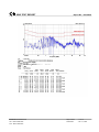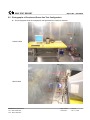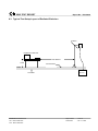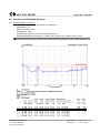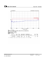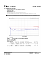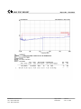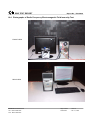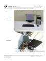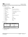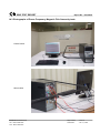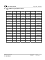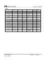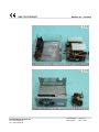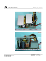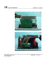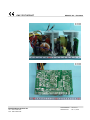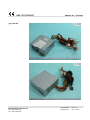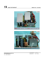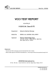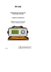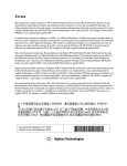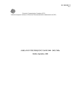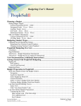
1
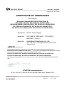
EMC TEST REPORT Report No. : EC812508 EMC TEST REPORT according to European Standard EN 55022:2006 Class B, EN 61000-3-2:2006, EN 61000-3-3:1995/A2:2005, EN 55024:1998/A1:2001/A2:2003 ( IEC 61000-4-2:1995/A2:2000, EC 61000-4-3:1995/A2:2002, IEC 61000-4-4:1995/A2:2001, IEC 61000-4-6:1996/A1:2000, IEC 61000-4-8:1993/A1:2000 ) Equipment : DC-DC Power Supply Model No. : STC-24XXX、BES-640C、STC-48XXX、 BES-640T ( X=0~9 ) Applicant : Synocean Technology Co., Ltd. 4F-1, 201, Sec. II, Ho Ping East Road, Taipei 10664, Taiwan, R.O.C. The test result refers exclusively to the test presented test model / sample. Without written approval of SPORTON International Inc., the test report shall not be reproduced except in full. This test report is only applicable to European Community. SPORTON International Inc. 6F, No. 106, Sec. 1, Hsin Tai Wu Rd., Hsi Chih, Taipei Hsien, Taiwan, R.O.C. SPORTON International Inc. TEL : 886-2-2696-2468 FAX : 886-2-2696-2255 EMC TEST REPORT Report No. : EC812508 Table of Contents History of this test report...................................................................................................................................iii CERTIFICATE OF COMPLIANCE........................................................................................................................1 1. General Description of Equipment under Test.............................................................................................2 1.1 Applicant..........................................................................................................................................................................................2 1.2 Manufacturer ...................................................................................................................................................................................2 1.3 Basic Description of Equipment under Test ....................................................................................................................................2 1.4 Feature of Equipment under Test ...................................................................................................................................................2 2. Test Configuration of Equipment under Test ...............................................................................................3 2.1 Test Manner ....................................................................................................................................................................................3 2.2 Description of Test System .............................................................................................................................................................3 3. Test Software ...................................................................................................................................................6 4. General Information of Test............................................................................................................................7 4.1 Test Facility .....................................................................................................................................................................................7 4.2 Test Voltage ....................................................................................................................................................................................7 4.3 Standard for Methods of Measurement...........................................................................................................................................7 4.4 Test in Compliance with ..................................................................................................................................................................7 4.5 Frequency Range Investigated .......................................................................................................................................................7 4.6 Test Distance ..................................................................................................................................................................................7 5. Test of Conducted Power line ........................................................................................................................8 5.1 Description of Major Test Instruments ............................................................................................................................................8 5.2 Test Procedures ..............................................................................................................................................................................9 5.3 Typical Test Setup Layout of Conducted Power line ....................................................................................................................10 5.4 Test Result of AC Power line Conducted Emission ......................................................................................................................11 5.5 Photographs of Conducted Power line Test Configuration ...........................................................................................................15 6. Test of Radiated Emission mission .............................................................................................................16 6.1 Description of Major Test Instruments ..........................................................................................................................................16 6.2 Test Procedures ............................................................................................................................................................................17 6.3 Typical Test Setup Layout of Radiated Emission..........................................................................................................................18 6.4 Test Result of Radiated Emission .................................................................................................................................................19 6.5 Photographs of Radiated Emission Test Configuration ................................................................................................................27 7. Harmonics Test..............................................................................................................................................28 8. Voltage Fluctuations Test.............................................................................................................................29 9. Electrostatic Discharge Immunity Test (ESD) ............................................................................................30 9.1 Test Setup .....................................................................................................................................................................................30 9.2 Test Setup for Tests Performed in Laboratory ..............................................................................................................................31 9.3 ESD Test Procedure .....................................................................................................................................................................32 9.4 Test Severity Levels ......................................................................................................................................................................33 9.5 Test Points ....................................................................................................................................................................................34 9.6 Photographs of Electrostatic Discharge Immunity Test ................................................................................................................35 10. Radio Frequency Electromagnetic Field Immunity Test (RS).................................................................36 10.1 Test Setup .....................................................................................................................................................................................36 10.2 Test Procedure..............................................................................................................................................................................37 10.3 Test Severity Levels ......................................................................................................................................................................37 10.4 Photographs of Radio Frequency Electromagnetic Field Immunity Test ......................................................................................38 11. Electrical Fast Transient/Burst Immunity Test (EFT/BURST) .................................................................39 SPORTON International Inc. TEL : 886-2-2696-2468 FAX : 886-2-2696-2255 Page No. : i Issued Date : Feb. 12, 2008 EMC TEST REPORT Report No. : EC812508 11.1 Test Setup .....................................................................................................................................................................................39 11.2 Test on Power Line .......................................................................................................................................................................40 11.3 Test on Communication Lines.......................................................................................................................................................40 11.4 Test Procedure..............................................................................................................................................................................40 11.5 Test Severity Levels ......................................................................................................................................................................41 11.6 Photographs of Electrical Fast Transient/Burst Immunity Test .....................................................................................................42 12. Surge Immunity Test ...................................................................................................................................43 13. Conducted Disturbances Induced by Radio-Frequency Field Immunity Test ( CS )............................44 13.1 Test Level......................................................................................................................................................................................44 13.2 Operating Condition ......................................................................................................................................................................44 13.3 Test Procedure..............................................................................................................................................................................45 13.4 Photographs of CS Test ................................................................................................................................................................46 14. Power Frequency Magnetic Field immunity tests ....................................................................................47 14.1 Test Record...................................................................................................................................................................................47 14.2 Test Setup .....................................................................................................................................................................................47 14.3 Photographs of Power Frequency Magnetic Field immunity tests ................................................................................................48 15. Voltage Dips and Voltage Interruption Immunity Tests ..........................................................................49 16. List of Measuring Equipment Used ...........................................................................................................50 17. Declaration of Conformity and the CE Mark .............................................................................................52 Appendix A. Photographs of EUT........................................................................................................ A1 ~ A15 SPORTON International Inc. TEL : 886-2-2696-2468 FAX : 886-2-2696-2255 Page No. : ii Issued Date : Feb. 12, 2008 EMC TEST REPORT Report No. : EC812508 History of this test report Original Report Issue Date: Feb. 12, 2008 Report No. Issue Date SPORTON International Inc. TEL : 886-2-2696-2468 FAX : 886-2-2696-2255 Description Page No. : iii Issued Date : Feb. 12, 2008 EMC TEST REPORT Report No. : EC812508 Certificate No. : EC812508 CERTIFICATE OF COMPLIANCE according to European Standard EN 55022:2006 Class B, EN 61000-3-2:2006, EN 61000-3-3:1995/A2:2005, EN 55024:1998/A1:2001/A2:2003 ( IEC 61000-4-2:1995/A2:2000, EC 61000-4-3:1995/A2:2002, IEC 61000-4-4:1995/A2:2001, IEC 61000-4-6:1996/A1:2000, IEC 61000-4-8:1993/A1:2000 ) Equipment : DC-DC Power Supply Model No. : STC-24XXX、BES-640C、STC-48XXX、 BES-640T ( X=0~9 ) Applicant : SYNOCEAN TECHNOLOGY CO., LTD. 4F-1, 201, Sec. II, Ho Ping East Road, Taipei 10664, Taiwan, R.O.C. I HEREBY CERTIFY THAT : The measurements shown in this test report were made in accordance with the procedures given in EUROPEAN COUNCIL DIRECTIVE 2004/108/EC. The equipment was passed the test performed according to European Standard EN 55022: 2006 Class B, EN 61000-3-2:2006, EN 61000-3-3:1995/A2:2005, EN 55024:1998/A1:2001/A2:2003 ( IEC 61000-4-2:1995/A2:2000, EC 61000-4-3:1995/A2:2002, IEC 61000-4-4:1995/A2:2001, IEC 61000-4-6:1996/A1:2000, IEC 61000-4-8:1993/A1:2000 ). The test was carried out on Feb. 05, 2008 at SPORTON International Inc. LAB. Jones Chang Supervisor SPORTON International Inc. 6F, No. 106, Sec. 1, Hsin Tai Wu Rd., Hsi Chih, Taipei Hsien, Taiwan, R.O.C. SPORTON International Inc. TEL : 886-2-2696-2468 FAX : 886-2-2696-2255 Page Number : 1 of 52 Issued Date : Feb. 12, 2008 EMC TEST REPORT Report No. : EC812508 1. General Description of Equipment under Test 1.1 Applicant Synocean Technology Co., Ltd. 4F-1, 201, Sec. II, Ho Ping East Road, Taipei 10664, Taiwan, R.O.C. 1.2 Manufacturer Same as 1.1 1.3 Basic Description of Equipment under Test Equipment : DC-DC Power Supply Model No. : STC-24XXX、BES-640C、STC-48XXX、BES-640T ( X=0~9 ) Power Supply Type : From battery DC Power Cable : Non-Shielded, 1.2m, 2 pin 1.4 Feature of Equipment under Test “ Please refer to user manual “ SPORTON International Inc. TEL : 886-2-2696-2468 FAX : 886-2-2696-2255 Page Number : 2 of 52 Issued Date : Feb. 12, 2008 EMC TEST REPORT Report No. : EC812508 2. Test Configuration of Equipment under Test 2.1 Test Manner a. During testing, the interface cables and equipment positions were varied according to European Standard EN 55022. b. The complete test system included Compaq PC, Sony Monitor, EPSON Printer, ACEEX Modem, BTC PS/2 Keyboard, and Microsoft Mouse, DC Source and EUT for EMI test. c. The following test modes were for final test: Mode 1. Full system, Power Source: DC 24V Mode 2. Full system, Power Source: DC 48V d. The complete test system included Compaq PC, ViewSonic LCD Monitor, Dell PS/2 keyboard and HP PS/2 Mouse and DC Source for EMS test. Mode 1. Minimal system, Power Source: DC 24V Mode 2. Minimal system, Power Source: DC 48V e. Frequency range investigated: conduction 150 KHz to 30 MHz, radiation 30 MHz to 1000MHz. 2.2 Description of Test System < EMI > Support Unit 1. – PC (Compaq) FCC ID Model No. Power Supply Type Power Cord Remark Support Unit 2. – Monitor (Sony) FCC ID Model No. Power Supply Type Power Cord Data Cable Remark Support Unit 3. -- Printer (EPSON) FCC ID Model No. Power Supply Type Power Cord Data Cable Remark SPORTON International Inc. TEL : 886-2-2696-2468 FAX : 886-2-2696-2255 : N/A : D380MX : Switching : Non-Shielded : This support device was tested to comply with FCC standards and authorized under a declaration of conformity. : N/A : G420 : Switching : Non-Shielded : D-Shielded, 1.8m : This support device was tested to comply with FCC standards and authorized under a declaration of conformity. : N/A : LQ-300+ : Linear : Non-Shielded : D-Shielded, 1.8m : This support device was tested to comply with FCC standards and authorized under a declaration of conformity. Page Number : 3 of 52 Issued Date : Feb. 12, 2008 EMC TEST REPORT Support Unit 4. – Modem (ACEEX) FCC ID Model No. Power Supply Type Power Cord Data Cable Report No. : EC812508 :IFAXDM1414 : DM141 : Linear : Non-Shielded : D-Shielded, 1.2m Support Unit 5. – PS/2 Keyboard (BTC) FCC ID : N/A Model No. : 9110 Data Cable : AL-F-Shielded, 1.7m Remark : This support device was tested to comply with FCC standards and authorized under a declaration of conformity. Support Unit 6. -- Mouse (Microsoft) FCC ID Model No. Data Cable Remark : N/A : 1004 : D-Shielded, 1.8 m : This support device was tested to comply with FCC standards and authorized under a declaration of conformity. Support Unit 7. -- DC Source (YUASA) <EMS> Support Unit 1. – PC (Compaq) FCC ID Model No. Power Supply Type Power Cord Remark : N/A : Evo D380MX : Switching : Non-Shielded : This support device was tested to comply with FCC standards and authorized under a declaration of conformity. Support Unit 2. – LCD Monitor (ViewSonic) FCC ID : N/A Model No. : VX700 Power Supply Type : Switching Power Cord : Non-Shielded Data Cable : D-Shielded, 1.8m Remark : This support device was tested to comply with FCC standards and authorized under a declaration of conformity. SPORTON International Inc. TEL : 886-2-2696-2468 FAX : 886-2-2696-2255 Page Number : 4 of 52 Issued Date : Feb. 12, 2008 EMC TEST REPORT Report No. : EC812508 Support Unit 3. – PS/2 Keyboard (DELL) FCC ID : N/A Model No. : SK-8110 Data Cable : AL-F-Shielded, 1.8m Remark : This support device was tested to comply with FCC standards and authorized under a declaration of conformity. Support Unit 4. – PS/2 Mouse (HP) FCC ID Model No. Data Cable Remark : N/A : M-S69 : AL-F-Shielded, 1.8m : This support device was tested to comply with FCC standards and authorized under a declaration of conformity. Support Unit 5. – DC Source (YUASA) SPORTON International Inc. TEL : 886-2-2696-2468 FAX : 886-2-2696-2255 Page Number : 5 of 52 Issued Date : Feb. 12, 2008 EMC TEST REPORT Report No. : EC812508 3. Test Software < EMI > & <EMS> An executive program, “EMCTEST.EXE” under Win XP, which generate a complete line of continuously repeating “ H “ pattern was used as the test software. The program was executed as follows : a. Turn on the power of all equipment. b. The PC reads the test program from the hard disk drive and runs it. c. The PC sends " H " messages to the monitor, and the monitor displays " H " patterns on the screen. d. The PC sends " H " messages to the printer, then the printer prints them on the paper. e. The PC sends " H " messages to the modem. f. Repeat the steps from c to e. SPORTON International Inc. TEL : 886-2-2696-2468 FAX : 886-2-2696-2255 Page Number : 6 of 52 Issued Date : Feb. 12, 2008 EMC TEST REPORT Report No. : EC812508 4. General Information of Test 4.1 Test Facility <EMI> Test Site Location : Test Site No. No. 52, Hwa Ya 1st Rd., Hwa Ya Technology Park, Kwei-Shan Hsiag, Tao Yuan Hsien, Taiwan, R.O.C. TEL : 886-3-327-3456 FAX : 886-3-318-0055 : CO04-HY, 10CH02-HY <EMS> Test Site Location : No. 52, Hwa Ya 1st Rd., Hwa Ya Technology Park, Kwei-Shan Hsiag, Tao Yuan Hsien, Taiwan, R.O.C. TEL : 886-3-327-3456 FAX : 886-3-318-0055 4.2 Test Voltage DC 24V / DC 48V 4.3 Standard for Methods of Measurement EMI Test (conduction and radiation) : European Standard EN 55022 Class B Harmonics Test : European Standard EN 61000-3-2. Voltage Fluctuations Test : European Standard EN 61000-3-3. EMS Test : European Standard EN 55024. (ESD: IEC 61000-4-2, RS: IEC 61000-4-3, EFT: IEC 61000-4-4, CS: IEC 61000-4-6, Power Frequency Magnetic Field: IEC 61000-4-8) 4.4 Test in Compliance with EMI Test (conduction and radiation) : European Standard EN 55022 Class B Harmonics Test : European Standard EN 61000-3-2. Voltage Fluctuations Test : European Standard EN 61000-3-3. EMS Test : European Standard EN 55024. (ESD: IEC 61000-4-2, RS: IEC 61000-4-3, EFT: IEC 61000-4-4, CS: IEC 61000-4-6, Power Frequency Magnetic Field: IEC 61000-4-8) 4.5 Frequency Range Investigated a. Conducted emission test: from 150 kHz to 30 MHz b. Radiated emission test: from 30 MHz to 1,000 MHz c. Radio frequency electromagnetic field immunity test : 80-1000 MHz. 4.6 Test Distance a. The test distance of radiated emission test from antenna to EUT is 10 M. b. The test distance of radio frequency electromagnetic field immunity test from antenna to EUT is 3 M. SPORTON International Inc. TEL : 886-2-2696-2468 FAX : 886-2-2696-2255 Page Number : 7 of 52 Issued Date : Feb. 12, 2008 EMC TEST REPORT Report No. : EC812508 5. Test of Conducted Power line Conducted Emissions were measured from 150 kHz to 30 MHz with a bandwidth of 9 kHz and return leads of the EUT according to the methods defined in European Standard EN 55022 Clause 9. The EUT was placed on a nonmetallic stand in a shielded room 0.8 meters above the ground plane as shown in section 5.3. The interface cables and equipment positioning were varied within limits of reasonable applications to determine the position producing maximum conducted emissions. 5.1 Description of Major Test Instruments z Test Receiver ( R&S ESCS 30 ) Attenuation 10 dB Start Frequency 0.15 MHz Stop Frequency 30 MHz IF Bandwidth 9 kHz SPORTON International Inc. TEL : 886-2-2696-2468 FAX : 886-2-2696-2255 Page Number : 8 of 52 Issued Date : Feb. 12, 2008 EMC TEST REPORT Report No. : EC812508 5.2 Test Procedures a. The EUT was placed on a desk 0.8 meters height from the metal ground plane and 0.4 meter from the conducting wall of the shielding room and it was kept at least 0.8 meters from any other grounded conducting surface. b. Connect EUT to the power mains through a line impedance stabilization network (LISN). c. Connect Telecommunication port to ISN (Impedance Stabilization Network) d. All the support units are connect to the other LISN. e. The LISN provides 50 ohm coupling impedance for the measuring instrument. f. The CISPR states that a 50 ohm , 50 microhenry LISN should be used. g. Both sides of AC line were checked for maximum conducted interference. h. The frequency range from 150 kHz to 30 MHz was searched. i. Set the test-receiver system to Peak Detect Function and Specified Bandwidth with Maximum Hold Mode. SPORTON International Inc. TEL : 886-2-2696-2468 FAX : 886-2-2696-2255 Page Number : 9 of 52 Issued Date : Feb. 12, 2008 EMC TEST REPORT Report No. : EC812508 5.3 Typical Test Setup Layout of Conducted Power line 10 cm 80 cm to the ground plane L.I.S.N. SPORTON International Inc. TEL : 886-2-2696-2468 FAX : 886-2-2696-2255 L.I.S.N. Page Number : 10 of 52 Issued Date : Feb. 12, 2008 EMC TEST REPORT Report No. : EC812508 5.4 Test Result of AC Power line Conducted Emission 5.4.1 Test Mode: Mode 1 (DC 24V) Frequency Range of Test : from 0.15 MHz to 30 MHz Temperature : 25 ℃ Relative Humidity : 55 % Test Engineer : Ken Corrected Reading (dBuV) = LISN Factor + Cable Loss + Read Level = Level All emissions not reported here are more than 10 dB below the prescribed limit. ■ The test was passed at the minimum margin that marked by the frame in the following table STC-24XXX、BES-640C SPORTON International Inc. TEL : 886-2-2696-2468 FAX : 886-2-2696-2255 Page Number : 11 of 52 Issued Date : Feb. 12, 2008 EMC TEST REPORT Report No. : EC812508 STC-24XXX、BES-640C SPORTON International Inc. TEL : 886-2-2696-2468 FAX : 886-2-2696-2255 Page Number : 12 of 52 Issued Date : Feb. 12, 2008 EMC TEST REPORT Report No. : EC812508 5.4.2 Test Mode: Mode 2 (DC 48V) Frequency Range of Test : from 0.15 MHz to 30 MHz Temperature : 25 ℃ Relative Humidity : 55 % Test Engineer : Ken Corrected Reading (dBuV) = LISN Factor + Cable Loss + Read Level = Level All emissions not reported here are more than 10 dB below the prescribed limit. ■ The test was passed at the minimum margin that marked by the frame in the following table STC-48XXX、BES-640T SPORTON International Inc. TEL : 886-2-2696-2468 FAX : 886-2-2696-2255 Page Number : 13 of 52 Issued Date : Feb. 12, 2008 EMC TEST REPORT Report No. : EC812508 STC-48XXX、BES-640T SPORTON International Inc. TEL : 886-2-2696-2468 FAX : 886-2-2696-2255 Page Number : 14 of 52 Issued Date : Feb. 12, 2008 EMC TEST REPORT Report No. : EC812508 5.5 Photographs of Conducted Power line Test Configuration z The photographs show the configuration that generates the maximum emission. FRONT VIEW REAR VIEW SPORTON International Inc. TEL : 886-2-2696-2468 FAX : 886-2-2696-2255 Page Number : 15 of 52 Issued Date : Feb. 12, 2008 EMC TEST REPORT Report No. : EC812508 6. Test of Radiated Emission mission Radiated emissions from 30 MHz to 1000 MHz were measured with a bandwidth of 120 kHz according to the methods defines in European Standard EN 55022, Clause 10 and AS/NZS CISPR 22. The EUT was placed on a nonmetallic stand, 0.8 meter above the ground plane, as shown in section 6.3. The interface cables and equipment positions were varied within limits of reasonable applications to determine the positions producing maximum radiated emissions. 6.1 Description of Major Test Instruments z Amplifier (Agilent 8447D) RF Gain 25 dB Signal Input 9 KHz to 1.3 GHz z Spectrum Analyzer (R&S FSP7 ) Attenuation 10 dB Start Frequency 30 MHz Stop Frequency 1000 MHz Resolution Bandwidth 120 KHz Signal Input 9 KHz to 7 GHz z Test Receiver (R&S ESI) Attenuation 10 dB Start Frequency 30 MHz Stop Frequency 1000 MHz Resolution Bandwidth 120 KHz Signal Input 9kHz to 2.75 GHz SPORTON International Inc. TEL : 886-2-2696-2468 FAX : 886-2-2696-2255 Page Number : 16 of 52 Issued Date : Feb. 12, 2008 EMC TEST REPORT Report No. : EC812508 6.2 Test Procedures a. The EUT was placed on a rotatable table top 0.8 meter above ground. b. The EUT was set 10 meters from the interference-receiving antenna which was mounted on the top of a variable height antenna tower. c. The table was rotated 360 degrees to determine the position of the highest radiation. d. The antenna is a half wave dipole and its height is varied between one meter and four meters above ground to find the maximum value of the field strength both horizontal polarization and vertical polarization of the antenna are set to make the measurement. e. For each suspected emission the EUT was arranged to its worst case and then tune the antenna tower (from 1 M to 4 M) and turn table (from 0 degree to 360 degrees) to find the maximum reading. f. Set the test-receiver system to Peak Detect Function and specified bandwidth with Maximum Hold Mode. g. If the emission level of the EUT in peak mode was 3 dB lower than the limit specified, then testing will be stopped and peak values of EUT will be reported, otherwise, the emissions which do not have 3 dB margin will be repeated one by one using the quasi-peak method and reported. SPORTON International Inc. TEL : 886-2-2696-2468 FAX : 886-2-2696-2255 Page Number : 17 of 52 Issued Date : Feb. 12, 2008 EMC TEST REPORT Report No. : EC812508 6.3 Typical Test Setup Layout of Radiated Emission Antenna Equipment under Test Test distance 0.8 M Ground Plane Receiver TurnTable SPORTON International Inc. TEL : 886-2-2696-2468 FAX : 886-2-2696-2255 Page Number : 18 of 52 Issued Date : Feb. 12, 2008 EMC TEST REPORT Report No. : EC812508 6.4 Test Result of Radiated Emission 6.4.1 Test Mode: Mode 1 (DC 24V) Frequency Range of Test : from 30 MHz to 1000 MHz Temperature : 25 ℃ Relative Humidity : 63 % Test Engineer : Nicky Emission level (dBμV/m) = 20 log Emission level (μV/m) Corrected Reading: Antenna Factor + Cable Loss + Read Level - Preamp Factor = Level ■ The test was passed at the minimum margin that marked by the frame in the following test record STC-24XXX、BES-640C SPORTON International Inc. TEL : 886-2-2696-2468 FAX : 886-2-2696-2255 Page Number : 19 of 52 Issued Date : Feb. 12, 2008 EMC TEST REPORT Report No. : EC812508 STC-24XXX、BES-640C SPORTON International Inc. TEL : 886-2-2696-2468 FAX : 886-2-2696-2255 Page Number : 20 of 52 Issued Date : Feb. 12, 2008 EMC TEST REPORT Report No. : EC812508 STC-24XXX、BES-640C SPORTON International Inc. TEL : 886-2-2696-2468 FAX : 886-2-2696-2255 Page Number : 21 of 52 Issued Date : Feb. 12, 2008 EMC TEST REPORT Report No. : EC812508 STC-24XXX、BES-640C SPORTON International Inc. TEL : 886-2-2696-2468 FAX : 886-2-2696-2255 Page Number : 22 of 52 Issued Date : Feb. 12, 2008 EMC TEST REPORT Report No. : EC812508 6.4.2 Test Mode: Mode 2 (DC 48V) Frequency Range of Test : from 30 MHz to 1000 MHz Temperature : 25 ℃ Relative Humidity : 63 % Test Engineer : Nicky Emission level (dBμV/m) = 20 log Emission level (μV/m) Corrected Reading: Antenna Factor + Cable Loss + Read Level - Preamp Factor = Level ■ The test was passed at the minimum margin that marked by the frame in the following test record STC-48XXX、BES-640T SPORTON International Inc. TEL : 886-2-2696-2468 FAX : 886-2-2696-2255 Page Number : 23 of 52 Issued Date : Feb. 12, 2008 EMC TEST REPORT Report No. : EC812508 STC-48XXX、BES-640T SPORTON International Inc. TEL : 886-2-2696-2468 FAX : 886-2-2696-2255 Page Number : 24 of 52 Issued Date : Feb. 12, 2008 EMC TEST REPORT Report No. : EC812508 STC-48XXX、BES-640T SPORTON International Inc. TEL : 886-2-2696-2468 FAX : 886-2-2696-2255 Page Number : 25 of 52 Issued Date : Feb. 12, 2008 EMC TEST REPORT Report No. : EC812508 STC-48XXX、BES-640T SPORTON International Inc. TEL : 886-2-2696-2468 FAX : 886-2-2696-2255 Page Number : 26 of 52 Issued Date : Feb. 12, 2008 EMC TEST REPORT Report No. : EC812508 6.5 Photographs of Radiated Emission Test Configuration z The photographs show the configuration that generates the maximum emission. FRONT VIEW REAR VIEW SPORTON International Inc. TEL : 886-2-2696-2468 FAX : 886-2-2696-2255 Page Number : 27 of 52 Issued Date : Feb. 12, 2008 EMC TEST REPORT Report No. : EC812508 7. Harmonics Test The power supply of this EUT is DC voltage. Harmonics test is not applicable for this EUT. SPORTON International Inc. TEL : 886-2-2696-2468 FAX : 886-2-2696-2255 Page Number : 28 of 52 Issued Date : Feb. 12, 2008 EMC TEST REPORT Report No. : EC812508 8. Voltage Fluctuations Test The power supply of this EUT is DC voltage. Voltage Fluctuations is not applicable for this EUT. SPORTON International Inc. TEL : 886-2-2696-2468 FAX : 886-2-2696-2255 Page Number : 29 of 52 Issued Date : Feb. 12, 2008 EMC TEST REPORT Report No. : EC812508 9. Electrostatic Discharge Immunity Test (ESD) z FINAL TEST RESULT : PASS z Pass Performance Criteria : A z Required Performance Criteria : B z Basic Standard : IEC 61000-4-2:1995/A2:2000 z Product Standard : EN 55024:1998/A1:2001/A2:2003 z Level : 3 for air discharge 2 for contact discharge z Test Voltage : ±2 / ±4 / ±8 KV for air discharge z Temperature ±2 / ±4 KV for contact discharge : 25℃ z Relative Humidity : 50% z Atmospheric Pressure : 100 kPa z Test Date : Feb. 04, 2008 z Test Mode : Mode 1, Mode 2 z Test Engineer : Mars z Observation : The EUT has no on slots, apertures, or insulating surfaces. So the air discharge test is not applicable. 9.1 Test Setup The test setup consists of the test generator, EUT and auxiliary instrumentation necessary to perform DIRECT and INDIRECT application of discharges to the EUT as applicable, in the follow manner : a. CONTACT DISCHARGE to the conductive surfaces and to coupling plane; b. AIR DISCHARGE at insulating surfaces. The preferred test method is that of type tests performed in laboratories and the only accepted method of demonstrating conformance with this standard. The EUT was arranged as closely as possible to arrangement in final installed conditions. SPORTON International Inc. TEL : 886-2-2696-2468 FAX : 886-2-2696-2255 Page Number : 30 of 52 Issued Date : Feb. 12, 2008 EMC TEST REPORT Report No. : EC812508 9.2 Test Setup for Tests Performed in Laboratory A ground reference plane was provided on the floor of the test site. It was a metallic sheet (copper or aluminum) of 0.25 mm, minimum thickness; other metallic may be used but they shall have at least 0.65 mm thickness. In the SPORTON EMC LAB., we provided 1 mm thickness aluminum ground reference plane or 1 mm thickness stainless steel ground reference plane. The minimum size of the ground reference plane is 1 m x 1 m, the exact size depending on the dimensions of the EUT. It was connected to the protective grounding system. The EUT was arranged and connected according to its functional requirements. A distance of 1m minimum was provided between the EUT and the wall of the lab. and any other metallic structure. In cases where this length exceeds the length necessary to apply the discharges to the selected points, the excess length shall, where possible, be placed non-inductively off the ground reference plane and shall not come closer than 0.2m to other conductive parts in the test setup. Where the EUT is installed on a metal table, the table was connected to the reference plane via a cable with a 470k ohm resister located at each end, to prevent a build-up of charge. The test setup was consist a wooden table, 0.8m high, standing on the ground reference plane. A HCP, 1.6 m x 0.8 m, was placed on the table. The EUT and cables was isolated from the HCP by an insulating support 0.5 mm thick. The VCP size, 0.5 m x 0.5 m. SPORTON International Inc. TEL : 886-2-2696-2468 FAX : 886-2-2696-2255 Page Number : 31 of 52 Issued Date : Feb. 12, 2008 EMC TEST REPORT Report No. : EC812508 9.3 ESD Test Procedure a. In the case of air discharge testing the climatic conditions shall be within the following ranges: - ambient temperature: 15℃ to 35℃; - relative humidity : 30% to 60%; - atmospheric pressure : 86 kPa (860 mbar) to 106 kPa (1060 mbar). b. Test programs and software shall be chosen so as to exercise all normal modes of operation of the EUT. The use of special exercising software is encouraged, but permitted only where it can be shown that the EUT is being comprehensively exercised. c. The test voltage shall be increased from the minimum to the selected test severity level, in order to determine any threshold of failure. The final severity level should not exceed the product specification value in order to avoid damage to the equipment. d. The test shall be performed with both air discharge and contact discharge. On preselected points at least 10 single discharges (in the most sensitive polarity) shall be applied on air discharge. On preselected points at least 25 single discharges (in the most sensitive polarity) shall be applied on contact discharge. e. For the time interval between successive single discharges an initial value of one second is recommended. Longer intervals may be necessary to determine whether a system failure has occurred. f. In the case of contact discharges, the tip of the discharge electrode shall touch the EUT before the discharge switch is operated. g. In the case of painted surface covering a conducting substrate, the following procedure shall be adopted : - If the coating is not declared to be an insulating coating by the equipment manufacturer, then the pointed tip of the generator shall penetrate the coating so as to make contact with the conducting substrate. - Coating declared as insulating by the manufacturer shall only be submitted to the air discharge. - The contact discharge test shall not be applied to such surfaces. h. In the case of air discharges, the round discharge tip of the discharge electrode shall be approached as fast as possible (without causing mechanical damage) to touch the EUT . After each discharge, the ESD generator (discharge electrode) shall be removed from the EUT. The generator is then retriggered for a new single discharge. This procedure shall be repeated until the discharges are completed. In the case of an air discharge test, the discharge switch, which is used for contact discharge, shall be closed. SPORTON International Inc. TEL : 886-2-2696-2468 FAX : 886-2-2696-2255 Page Number : 32 of 52 Issued Date : Feb. 12, 2008 EMC TEST REPORT Report No. : EC812508 9.4 Test Severity Levels 9.4.1 Contact Discharge Level 1 2 3 4 Test Voltage (KV) of Contact discharge ±2 ±4 ±6 ±8 X Specified Remark : “X” is an open level. 9.4.2 Air Discharge Level 1 2 3 4 Test Voltage (KV) of Air Discharge ±2 ±4 ±8 ±15 X Specified Remark : “X” is an open level. SPORTON International Inc. TEL : 886-2-2696-2468 FAX : 886-2-2696-2255 Page Number : 33 of 52 Issued Date : Feb. 12, 2008 EMC TEST REPORT Report No. : EC812508 9.5 Test Points 9.5.1 Test Result of Contact Discharge Test Point Voltage Tested No. HCP (At Front) ±2 / ±4 KV BY 25 HCP (At Left) ±2 / ±4 KV BY 25 HCP (At Right) ±2 / ±4 KV BY 25 HCP (At Rear) ±2 / ±4 KV BY 25 VCP (At Front) ±2 / ±4 KV BY 25 VCP (At Left) ±2 / ±4 KV BY 25 VCP (At Right) ±2 / ±4 KV BY 25 VCP (At Rear) ±2 / ±4 KV BY 25 Case ±2 / ±4 KV BY 25 Screw ±2 / ±4 KV BY 25 SPORTON International Inc. TEL : 886-2-2696-2468 FAX : 886-2-2696-2255 Page Number : 34 of 52 Issued Date : Feb. 12, 2008 EMC TEST REPORT Report No. : EC812508 9.6 Photographs of Electrostatic Discharge Immunity Test FRONT VIEW REAR VIEW SPORTON International Inc. TEL : 886-2-2696-2468 FAX : 886-2-2696-2255 Page Number : 35 of 52 Issued Date : Feb. 12, 2008 EMC TEST REPORT Report No. : EC812508 10. Radio Frequency Electromagnetic Field Immunity Test (RS) z FINAL TEST RESULT : PASS z Pass Performance Criteria : A z Required Performance Criteria : A z Basic Standard : IEC 61000-4-3:1995/A2:2002 z Product Standard : EN 55024:1998/A1:2001/A2:2003 z Level : 2 z Frequency Range : 80-1000 MHz z Field Strength : 3 V/m (Modulated 80% AM) z Temperature : 24 ℃ z Relative Humidity : 51 % z Atmospheric Pressure : 100 kPa z Test Date : Feb. 04, 2008 z Test Mode : Mode 1, Mode 2 z Test Engineer : Mars z Observation : Normal 10.1 Test Setup NOTE : The SPORTON 7m x 4m x 4m semichoic chamber is compliance with the sixteen points uniform field requirement as stated in IEC 1000-4-3 Section 6.2. The procedure defined in this part requires the generation of electromagnetic fields within which the test sample is placed and its operation observed. To generate fields that are useful for simulation of actual (field) conditions may require significant antenna drive power and the resultant high field strength levels. To comply with local regulations and to prevent biological hazards to the testing personnel, it is recommended that these tests be carried out in a shielded enclosure or semichoic chamber. SPORTON International Inc. TEL : 886-2-2696-2468 FAX : 886-2-2696-2255 Page Number : 36 of 52 Issued Date : Feb. 12, 2008 EMC TEST REPORT Report No. : EC812508 10.2 Test Procedure a. The equipment to be tested is placed in the center of the enclosure on a wooden table. The equipment is then connected to power and signal leads according to pertinent installation instructions. b. The bilog antenna which is enabling the complete frequency range of 80-1000 MHz is placed 3m away from the equipment. The required field strength is determined by placing the field strength meter(s) on top of or directly alongside the equipment under test and monitoring the field strength meter via a remote field strength indicator outside the enclosure while adjusting the continuous-wave to the applicable antennae. c. The test is normally performed with the generating antenna facing each of four sides of the EUT. The polarization of the field generated by the broadband (bilog) antenna necessitates testing each position twice, once with the antenna positioned vertically and again with the antenna positioned horizontally. d. At each of the above conditions, the frequency range is swept 80-1000 MHz, pausing to adjust the R.F. signal level or to switch oscillators and antenna. The rate of sweep is in the order of 1.5*10-3 decades/s. The sensitive frequencies or frequencies of dominant interest may be discretely analyzed. 10.3 Test Severity Levels Frequency Band : 80-1000 MHz Level Test field strength (V/m) 1 1 2 3 3 10 X Specified Remark : “X” is an open class. SPORTON International Inc. TEL : 886-2-2696-2468 FAX : 886-2-2696-2255 Page Number : 37 of 52 Issued Date : Feb. 12, 2008 EMC TEST REPORT Report No. : EC812508 10.4 Photographs of Radio Frequency Electromagnetic Field Immunity Test FRONT VIEW REAR VIEW SPORTON International Inc. TEL : 886-2-2696-2468 FAX : 886-2-2696-2255 Page Number : 38 of 52 Issued Date : Feb. 12, 2008 EMC TEST REPORT Report No. : EC812508 11. Electrical Fast Transient/Burst Immunity Test (EFT/BURST) z FINAL TEST RESULT : PASS z Pass Performance Criteria : A z Required Performance Criteria : B z Basic Standard : IEC 61000-4-4:1995/A2:2001 z Product Standard : EN 55024:1998/A1:2001/A2:2003 z Level : on Power Supply -- 1 z z Test Voltage Temperature : : on Power Supply -- ±0.5 KV 24 ℃ z Relative Humidity : 52 % z Atmospheric Pressure : 100 kPa z Test Date : Feb. 04, 2008 z Test Mode : Mode 1, Mode 2 z Test Engineer : Mars z Observation : Normal 11.1 Test Setup The EUT was placed on a ground reference plane and was insulated from it by an insulating support about 0.1m thick. If the EUT is table-top equipment, it was located approximately 0.8m above the GRP.. The GRP. was a metallic sheet (copper or aluminum) of 0.25 mm ,minimum thickness; other metallic may be used but they shall have at least 0.65 mm thickness. It shall project beyond the EUT by at least 0.1m on all sides and connected to the protective earth. In the SPORTON EMC LAB. we provided 1 mm thickness aluminum ground reference plane or 1 mm thickness stainless steel ground reference plane. The minimum size of the ground reference plane is 1 m x 1 m, the exact size depending on the dimensions of the EUT. It was connected to the protective grounding system. The EUT was arranged and connected according to its functional requirements. The minimum distance between the EUT and other conductive structures, except the GRP. beneath the EUT, was more than 0.5 m. Using the coupling clamp, the minimum distance between the coupling plates and all other conductive structures, except the GRP. beneath the EUT, was more than 0.5 m. The length of the signal and power lines between the coupling device and the EUT was 1m or less. SPORTON International Inc. TEL : 886-2-2696-2468 FAX : 886-2-2696-2255 Page Number : 39 of 52 Issued Date : Feb. 12, 2008 EMC TEST REPORT Report No. : EC812508 11.2 Test on Power Line a. The EFT/B-generator was located on the GRP.. The length from the EFT/B-generator to the EUT as not exceed 1 m. b. The EFT/B-generator provides the ability to apply the test voltage in a non-symmetrical condition to the power supply input terminals of the EUT. 11.3 Test on Communication Lines a. The coupling clamp is composed of a clamp unit for housing the cable (length more than 3 m), and was placed on the GRP.. b. The coupling clamp provides the ability of coupling the fast transient/bursts to the cable under test. 11.4 Test Procedure a. In order to minimize the effect of environmental parameters on test results, the climatic conditions when test is carrying out shall comply with the following requirements: - ambient temperature: 15℃ to 35℃; - relative humidity : 45% to 75%; - atmospheric pressure : 86 kPa (860 mbar) to 106 kPa (1060 mbar). b. In order to minimize the effect of environmental parameters on test results, the electromagnetic environment of the laboratory shall not influence the test results. c. The variety and diversity of equipment and systems to be tested make it difficult to establish general criteria for the evaluation of the effects of fast transients/bursts on equipment and systems. d. The test results may be classified on the basic of the operating conditions and the functional specification of the equipment under test, according to the following performance criteria : - Normal performance within the specification limits. - Temporary degradation or loss of function or performance which is self-recoverable. - Temporary degradation or loss of function or performance which requires operator intervention or system reset. - Degradation or loss of function which is not recoverable due to damage of equipment (components). SPORTON International Inc. TEL : 886-2-2696-2468 FAX : 886-2-2696-2255 Page Number : 40 of 52 Issued Date : Feb. 12, 2008 EMC TEST REPORT Report No. : EC812508 11.5 Test Severity Levels The following test severity levels are recommended for the fast transient/burst test : Open circuit output test voltage ± 10% Level On Power Supply On I/O signal, data and control line 1 0.5 KV 0.25 KV 2 1.0 KV 0.50 KV 3 2.0 KV 1.00 KV 4 4.0 KV 2.00 KV X Specified Specified Remark : “ X ” is an open level. The level is subject to negotiation between the user and the manufacturer or is specified by the manufacturer. SPORTON International Inc. TEL : 886-2-2696-2468 FAX : 886-2-2696-2255 Page Number : 41 of 52 Issued Date : Feb. 12, 2008 EMC TEST REPORT Report No. : EC812508 11.6 Photographs of Electrical Fast Transient/Burst Immunity Test FRONT VIEW REAR VIEW SPORTON International Inc. TEL : 886-2-2696-2468 FAX : 886-2-2696-2255 Page Number : 42 of 52 Issued Date : Feb. 12, 2008 EMC TEST REPORT Report No. : EC812508 12. Surge Immunity Test The power supply of this EUT is DC voltage. SURGE Immunity tests is not applicable for this EUT. SPORTON International Inc. TEL : 886-2-2696-2468 FAX : 886-2-2696-2255 Page Number : 43 of 52 Issued Date : Feb. 12, 2008 EMC TEST REPORT Report No. : EC812508 13. Conducted Disturbances Induced by Radio-Frequency Field Immunity Test ( CS ) z FINAL TEST RESULT : PASS z Pass Performance Criteria : A z Required Performance Criteria : A z Basic Standard : IEC 61000-4-6:1996/A1:2000 z Product Standard : EN 55024:1998/A1:2001/A2:2003 z Level : 2 z Test Voltage : 3 V/rms ( Modulated, 1KHz, 80%, AM ) z Frequency Range : 0.15 MHz to 80 MHz z Test Port : on DC Power z Dwell Time : 2.9 seconds z Frequency Step Size : 1% z Coupling Mode : M16SWM2 for DC power ports z Temperature : 24 ℃ z Relative Humidity : 53 % z Atmospheric Pressure : 100 kPa z Test Date : Feb. 04, 2008 z Test Mode : Mode 1, Mode 2 z Test Engineer : Mars z Observation : Normal 13.1 Test Level Level Voltage Level ( EMF ), 1 1V 2 3V 3 10 V x Specified NOTE - x is an open class. This level can be specified in the product specification. 13.2 Operating Condition Minimal system SPORTON International Inc. TEL : 886-2-2696-2468 FAX : 886-2-2696-2255 Page Number : 44 of 52 Issued Date : Feb. 12, 2008 EMC TEST REPORT Report No. : EC812508 13.3 Test Procedure a. The EUT shall be operated within its intended climatic conditions. The temperature and relative humidity should be recorded. b. This test method test can be performed without using a sell shielded enclosure. This is because the disturbance levels applied and the geometry of the setups are not likely to radiated a high amount of energy, especially at the lower frequencies. If under certain circumstances the radiated energy is too high, a shielded enclosure has to be used. c. The test shall be performed with the test generator connected to each of the coupling and decoupling devices in turn while the other non-excited RF-input ports of the coupling devices are terminated by a 50 ohm load resistor. d. The frequency range is swept from 150 KHz to 80 MHz, using the signal levels established during the setting process, and with the disturbance signal 80% amplitude modulated with a 1KHz sinewave, pausing to adjust the RF-signal level or to switch coupling devices as necessary. The rate of sweep shall no exceed 1.5 x 10⁻³ decades/s. Where the frequency is swept incrementally, the step size shall no exceed 1% of the start and thereafter 1% of the preceding frequency value. e. The dwell time at each frequency shall not be less than the time necessary for the EUT to be exercised, and able to respond. Sensitive frequencies e.g. clock frequency(ies) and harmonics or frequencies of dominant interest shall be analyzed separately. f. An alternative test procedure may be adopted, wherein the frequency range is swept incrementally, with a step size not exceeding 4% of the start ad thereafter 4% of the preceding frequency value. The test level should be at least twice the value of the specified test level. g. In cases of dispute, the test procedure using a step size not exceeding 1% of the start and thereafter 1% of preceding frequency value shall take precedence. h. Attempts should be made to fully exercise the EUT during testing, and to fully interrogate all exercise modes selected for susceptibility. i. The use of special exercising programs is recommended. j. Testing shall be performed according to a Test Plan, which shall be included in the test report. k. It may be necessary to carry out some investigatory testing in order to establish some aspects of the test plan. SPORTON International Inc. TEL : 886-2-2696-2468 FAX : 886-2-2696-2255 Page Number : 45 of 52 Issued Date : Feb. 12, 2008 EMC TEST REPORT Report No. : EC812508 13.4 Photographs of CS Test FRONT VIEW REAR VIEW SPORTON International Inc. TEL : 886-2-2696-2468 FAX : 886-2-2696-2255 Page Number : 46 of 52 Issued Date : Feb. 12, 2008 EMC TEST REPORT Report No. : EC812508 14. Power Frequency Magnetic Field immunity tests z z z z z z z z z z z z FINAL TEST RESULT Pass Performance Criteria Required Performance Criteria Basic Standard Product Standard Temperature : : : : : : PASS A A IEC 61000-4-8:1993/A1:2000 EN 55024:1998/A1:2001/A2:2003 24 ℃ Relative Humidity Atmospheric Pressure Test Date Test Mode Test Engineer Observation : : : : : : 53 % 100 kPa Feb. 04, 2008 Mode 1, Mode 2 Mars Normal 14.1 Test Record Power Frequency Magnetic Field 50Hz, 1A/m 50Hz, 1A/m 50Hz, 1A/m Testing duration 1.0 Min 1.0 Min 1.0 Min Coil Orientation X-axis Y-axis Z-axis Results Remark Pass Pass Pass Normal Normal Normal 14.2 Test Setup GRP : Ground plane Safety earth C2 : Signal circuit S: Insulating support L: Communication line EUT : Equipment under test B: To power supply source Lc : Induction coil D: To signal source, simulator E: Earth terminal G: To the test generator SPORTON International Inc. TEL : 886-2-2696-2468 FAX : 886-2-2696-2255 C1 : Power supply circuit A: Page Number : 47 of 52 Issued Date : Feb. 12, 2008 EMC TEST REPORT Report No. : EC812508 14.3 Photographs of Power Frequency Magnetic Field immunity tests FRONT VIEW REAR VIEW SPORTON International Inc. TEL : 886-2-2696-2468 FAX : 886-2-2696-2255 Page Number : 48 of 52 Issued Date : Feb. 12, 2008 EMC TEST REPORT Report No. : EC812508 15. Voltage Dips and Voltage Interruption Immunity Tests The power supply of this EUT is DC voltage. Voltage Dips and Voltage Interruptions Immunity tests is not applicable for this EUT. SPORTON International Inc. TEL : 886-2-2696-2468 FAX : 886-2-2696-2255 Page Number : 49 of 52 Issued Date : Feb. 12, 2008 EMC TEST REPORT Report No. : EC812508 16. List of Measuring Equipment Used < EMI > Instrument Manufacturer Model No. Serial No. Characteristics Calibration Date Remark EMC Receiver R&S ESCS 30 100174 9kHz – 2.75GHz Mar. 03, 2007 Conduction (CO04-HY) DC LISN ROIF HEINE LN-KFZ/200 03/10219 100kHz – 108MHz May 23, 2007 Conduction (CO04-HY) DC LISN ROIF HEINE LN-KFZ/200 03/10220 100kHz – 108MHz May 23, 2007 Conduction (CO04-HY) RF Cable-CON UTIFLEX 3102-26886-4 CB049 9kHz – 30MHz Apr. 20, 2007 Conduction (CO04-HY) EMI Filter LINDGREN LRE-2030 2651 < 450 Hz N/A Conduction (CO04-HY) 10m Semi Anechoic Chamber TDK SAC-10M 10CH02-HY 30MHz~1GHz 10m,3m Mar. 04, 2007 Radiation (10CH02-HY) Spectrum Analyzer R&S FSP7 100645 9KHz – 7GHz Jun. 15, 2007 Radiation (10CH02-HY) Receiver R&S ESI 1008 20Hz - 7GHz May 09, 2007 Radiation (10CH02-HY) Amplifier Agilent 8447D 2944A10827 100KHz – 1.3GHz Jun. 28, 2007 Radiation (10CH02-HY) Amplifier Agilent 8447D 2944A10828 100KHz – 1.3GHz Jun. 28, 2007 Radiation (10CH02-HY) Biconical Antenna Schwarzbeck VHBB 9124 287 30MHz –200MHz Dec. 22, 2007 Radiation (10CH02-HY) Schwarzbeck VUSLP 9111 207 200MHz -1GHz Dec. 22, 2007 Radiation (10CH02-HY) Log Antenna ※ Turn Table HD DS 430 430/360 0 ∼ 360 degree N/A Radiation (10CH02-HY) Antenna Mast HD MA240 240/664 1m-4m N/A Radiation (10CH02-HY) Antenna Mast HD MA240 240/667 1m-4m N/A Radiation (10CH02-HY) RF Cable-R10m Jye Bao RG142 CB027-INSIDE 30MHz~1GHz Nov. 30, 2007 Radiation (10CH02-HY) RF Cable-R10m Suhner Switzerland + BELDEN RG223/U + RG8/U CB026-DOOR 30MHz~1GHz Nov. 30, 2007 Radiation (10CH02-HY) Calibration Interval of instruments listed above is one year. SPORTON International Inc. TEL : 886-2-2696-2468 FAX : 886-2-2696-2255 Page Number : 50 of 52 Issued Date : Feb. 12, 2008 EMC TEST REPORT Report No. : EC812508 < EMS> Manufacturer Model No. Serial No. ESD Simulator SCHAFFNER NSG 435 5537 RS immunity Test system HP EMS test System 2062 80 MHz - 1 GHz 3V/m 10v/m Nov. 21. 2007 RS Amplifier AR 250W 1000AM1 320482 80 MHz - 1 GHz Nov. 21, 2007 RS Power Meter EMC Automation 438A 3513U04050 100 kHz - 4.2 GHz Nov. 22, 2007 RS Signal Generator HP 8648A 3426A00771 100 kHz - 1 GHz Nov. 23, 2007 RS Power Sensor HP 8481D 3318A13140 100 kHz - 1 GHz Nov. 23, 2007 RS Power Sensor HP 8482A 3318A26464 100 kHz - 1 GHz Nov. 23, 2007 RS Attenuator HP 8491A 53603 100 kHz - 1 GHz Nov. 22, 2007 RS Field Strength Monitoring Antennas (Probe) AR FP3000A 16077 0.1 MHz - 1 GHz Oct. 26, 2007 RS EFT Generator KEYTEK CE-40 9505216 0 kV - 4.4 kV Oct. 04, 2007 EFT Conducted Immunity Test System FRANKONIA CIT-10/75 1999010443 100 kHz - 266 MHz Apr. 03, 2007 CS Magnetic Generator FCC (KEYTEK) F-1000-4-8/9/1 0-L-1M 03003 ※ Characteristics Calibration Instrument Date Remark Air: 0 kV - 16.5 kV Mar. 12. 2007 Contact: 0 kV - 8 kV 30A//CONTINUOUS Sep. 21, 2007 100A/2Hrs 230A/30SEC ESD PFMF Calibration Interval of instruments listed above is one year. SPORTON International Inc. TEL : 886-2-2696-2468 FAX : 886-2-2696-2255 Page Number : 51 of 52 Issued Date : Feb. 12, 2008 EMC TEST REPORT Report No. : EC812508 17. Declaration of Conformity and the CE Mark There are three possible procedures pertaining to the declaration of conformity : 17.1 Conformity Testing and Declaration of Conformity by the Manufacturer or His Authorized Representative Established within the Community or by an Importer. - Article 10 (1) of the EMC Directive, - § 3 (1) no. 2a of the EMC Act. 17.2 Declaration of Conformity Issued by the Manufacturer or His Authorized Representative Established within the Community or by an Importer Following Testing of the Product and Issued of an EC certificate of conformity by a competent body. - Article 10 (2) of the EMC Directive, - § 3 (1) no. 2b of the EMC Act. 17.3 Declaration of Conformity Issued by the Manufacturer or His Authorized Representative Established within the Community or by an Importer Following Testing and Certification of the Product by a Notified Body. - Article 10 (5) of the EMC Directive, - § 3 (1) no. 2b of the EMC Act (radio transmitting installations). 17.4 Specimen For The CE Marking Of Electrical / Electronical Equipment The components of the CE marking shall have substantially the same vertical dimension, which may not be less than 5 mm. SPORTON International Inc. TEL : 886-2-2696-2468 FAX : 886-2-2696-2255 Page Number : 52 of 52 Issued Date : Feb. 12, 2008 EMC TEST REPORT REPORT NO. : EC812508 APPENDIX A. Photographs of EUT Type: DC 24V SPORTON International Inc. TEL : 886-2-2696-2468 FAX : 886-2-2696-2255 PAGE NUMBER : A1 OF A15 ISSUED DATE : Feb. 13, 2008 EMC TEST REPORT SPORTON International Inc. TEL : 886-2-2696-2468 FAX : 886-2-2696-2255 REPORT NO. : EC812508 PAGE NUMBER : A2 OF A15 ISSUED DATE : Feb. 13, 2008 EMC TEST REPORT SPORTON International Inc. TEL : 886-2-2696-2468 FAX : 886-2-2696-2255 REPORT NO. : EC812508 PAGE NUMBER : A3 OF A15 ISSUED DATE : Feb. 13, 2008 EMC TEST REPORT SPORTON International Inc. TEL : 886-2-2696-2468 FAX : 886-2-2696-2255 REPORT NO. : EC812508 PAGE NUMBER : A4 OF A15 ISSUED DATE : Feb. 13, 2008 EMC TEST REPORT SPORTON International Inc. TEL : 886-2-2696-2468 FAX : 886-2-2696-2255 REPORT NO. : EC812508 PAGE NUMBER : A5 OF A15 ISSUED DATE : Feb. 13, 2008 EMC TEST REPORT SPORTON International Inc. TEL : 886-2-2696-2468 FAX : 886-2-2696-2255 REPORT NO. : EC812508 PAGE NUMBER : A6 OF A15 ISSUED DATE : Feb. 13, 2008 EMC TEST REPORT SPORTON International Inc. TEL : 886-2-2696-2468 FAX : 886-2-2696-2255 REPORT NO. : EC812508 PAGE NUMBER : A7 OF A15 ISSUED DATE : Feb. 13, 2008 EMC TEST REPORT SPORTON International Inc. TEL : 886-2-2696-2468 FAX : 886-2-2696-2255 REPORT NO. : EC812508 PAGE NUMBER : A8 OF A15 ISSUED DATE : Feb. 13, 2008 EMC TEST REPORT REPORT NO. : EC812508 Type: DC 48V SPORTON International Inc. TEL : 886-2-2696-2468 FAX : 886-2-2696-2255 PAGE NUMBER : A9 OF A15 ISSUED DATE : Feb. 13, 2008 EMC TEST REPORT SPORTON International Inc. TEL : 886-2-2696-2468 FAX : 886-2-2696-2255 REPORT NO. : EC812508 PAGE NUMBER : A10 OF A15 ISSUED DATE : Feb. 13, 2008 EMC TEST REPORT SPORTON International Inc. TEL : 886-2-2696-2468 FAX : 886-2-2696-2255 REPORT NO. : EC812508 PAGE NUMBER : A11 OF A15 ISSUED DATE : Feb. 13, 2008 EMC TEST REPORT SPORTON International Inc. TEL : 886-2-2696-2468 FAX : 886-2-2696-2255 REPORT NO. : EC812508 PAGE NUMBER : A12 OF A15 ISSUED DATE : Feb. 13, 2008 EMC TEST REPORT SPORTON International Inc. TEL : 886-2-2696-2468 FAX : 886-2-2696-2255 REPORT NO. : EC812508 PAGE NUMBER : A13 OF A15 ISSUED DATE : Feb. 13, 2008 EMC TEST REPORT SPORTON International Inc. TEL : 886-2-2696-2468 FAX : 886-2-2696-2255 REPORT NO. : EC812508 PAGE NUMBER : A14 OF A15 ISSUED DATE : Feb. 13, 2008 EMC TEST REPORT SPORTON International Inc. TEL : 886-2-2696-2468 FAX : 886-2-2696-2255 REPORT NO. : EC812508 PAGE NUMBER : A15 OF A15 ISSUED DATE : Feb. 13, 2008