1
PLANET MAP-2000 / MAP-2000R MAP-2100 Mesh Network Manager (MnM) Management Utility – User manual Rev 2.6.2 March 2006 MnM Management Utility – User Manual Contents: 1 2 3 4 Overview Installation and Un-installation 4 5 2.1 2.2 5 9 To install the MnM Management Utility To Uninstall the MnM Management Utility How to use Mesh Network Manager (MnM) 12 3.1 3.2 3.3 3.4 3.5 3.6 3.7 3.8 3.9 3.10 3.11 3.12 3.13 3.14 3.15 3.16 3.17 3.18 3.19 3.20 3.21 3.22 3.23 3.24 3.25 3.26 3.27 3.28 3.29 3.30 13 14 16 17 18 19 19 22 23 25 25 25 25 26 28 29 30 30 32 33 35 36 38 45 46 47 47 48 52 54 Start-Up MnM Create New Scanner Load Scanner Save Settings / Save Settings As.. Load Settings Import Background Image Panes Scanner View View Topology Legend Refresh Topology Clear Topology Zoom Map Link Properties Pane Message Pane Change Target IP Address Scan Mode Plot Mode Show IP Address/Location Name Refresh Interval View History View and Configure Node Create VPN Connection Dial VPN Connection Reset Route Login View Status Quick Config Trap Viewer Closing MnM Mesh Node Manager 55 4.1 55 Introduction MnM Configuration Guide Page 2 of 110 MnM Management Utility – User Manual 4.2 4.3 4.4 4.5 4.6 File 56 4.2.1 File > Change SNMP Password 56 4.2.2 File > Exit 57 Status Menu 58 4.3.1 Status > System 58 Config Menu 60 4.4.1 Config > System 60 4.4.2 Config > Network > WAN 60 4.4.3 Config > Network > Local Network 65 4.4.4 Config > Network > WLAN 66 4.4.5 Config > Network > Node to Node 68 4.4.6 Config > Network > Route 71 4.4.7 Config > Security > MAC Access 73 4.4.8 Config > Security > Encryption and Authentication 75 4.4.9 Config > Services > DHCP Server 77 4.4.10 Config > Services > Firewall 80 4.4.11 Config > Services > NAT 84 4.4.12 Config > Services > VPN Server 85 4.4.13 Config > Services > NTP-Client 87 4.4.14 Config > Services > QoS 88 4.4.15 Config > Services > Traffic Shaping 89 4.4.16 Config > Services > Mobile IP 90 4.4.17 Config > Management > SNMP Password 91 4.4.18 Config > Management > Access Control 94 4.4.19 Config > Management > Remote Syslog 96 4.4.20 Config > User-Login > Login 96 4.4.21 Config > User-login > RADIUS 99 Monitor Menu 103 4.5.1 Monitor > ICMP 103 4.5.2 Monitor > IP ARP 104 4.5.3 Monitor > Learn Table 105 4.5.4 Monitor > Interfaces > Ethernet 106 4.5.5 Monitor > Interfaces > Wireless 107 Command Menu 108 4.6.1 Command > Upload/Download 108 4.6.2 Command > Reboot 109 4.6.3 Command > Reset 110 MnM Configuration Guide Page 3 of 110 MnM Management Utility – User Manual 1 Overview Mesh Network Manager (MnM) is user-friendly graphical interface, Javabased software application developed by the PLANET Technology Corp. A picture is worth a thousand words, by having a management-software that provides great visual over the whole network, the user has a better and easier understanding regarding the network. Generally, the MnM is capable of performing the monitor and management functions on the network. User can view the network within the coverage area or even remotely, via a WAN connection. Besides, network administrators can also perform configuration on the node by using the Mesh Node Manager through the secure and standard SNMP protocol. This documentation basically describes the installation and operation of the MnM v2.6.2, as well as some configuration guide on the node. MnM Configuration Guide Page 4 of 110 MnM Management Utility – User Manual 2 Installation and Un-installation This Section provides a step-by-step installation and un-installation guide for the Mesh Network Manager (MnM) Management Suite. 2.1 To install the MnM Management Utility To install the MnM Management Utility on your terminal, grab the MnM_Installer.exe application file found on the accompanying disk to any desired directory. Double-click the application file to start up the installation. After completely extracting, a loading window would show on the screen, as illustrated: Figure 2.1: Loading page when opening the installer. Once loaded, the installation wizard will be started up. Follow the simple steps directed by the wizard: (* Refer to the following screen shots) 1. Introduction – A brief introduction regarding the installer 2. Choose Install Folder – Select the desired directory to locate the software application. 3. Choose Shortcut Folder – Set the shortcut path. MnM Configuration Guide Page 5 of 110 MnM Management Utility – User Manual 4. Pre-Installation Summary – A review of the installation settings before starting the installation. 5. Installing – Display the progress of the installation. 6. Install Complete – Indicate the installation has been completed. Figure 2.2: Installing application - Introduction MnM Configuration Guide Page 6 of 110 MnM Management Utility – User Manual Figure 2.3: Installing application – Introduction Figure 2.4: Installing application – Choose Shortcut Folder MnM Configuration Guide Page 7 of 110 MnM Management Utility – User Manual Figure 2.5: Installing application – Pre-Installation Summary Figure 2.6: Installing application – Installing MnM Configuration Guide Page 8 of 110 MnM Management Utility – User Manual Figure 2.7: Installing application – Install Complete After complete the steps, you can start up the MnM Management Utility from the shortcut created. 2.2 To Uninstall the MnM Management Utility The MnM Management Utility Uninstaller wizard is built along with the application. You can uninstall the application by activate the wizard, namely Uninstall MnM Management Utility v2.x.x.exe, which is located in the program folder. Follow the three simple steps: 1. Introduction – About the uninstaller. The un-installation will be started once the Uninstall button is hit. 2. Uninstalling – The un-installation is in progress. Note that every files and folder created during the installation will be removed. (e.g. Record folder is created after the program runs, hence it will not be removed) 3. Uninstall Complete – Un-installation completed successfully. MnM Configuration Guide Page 9 of 110 MnM Management Utility – User Manual Figure 2.8: Uninstalling Application – Introduction Figure 2.9: Uninstalling Application – Uninstalling MnM Configuration Guide Page 10 of 110 MnM Management Utility – User Manual Figure 2.10: Uninstalling Application – Uninstall Complete MnM Configuration Guide Page 11 of 110 MnM Management Utility – User Manual 3 How to use Mesh Network Manager (MnM) This Section describes every single feature and operation of the Mesh Network Manager in details, in order to let the user to get familiar and comfortable when working with this graphical interface application effortlessly. Refer to the table below to get the definition of each button in the MnM toolbar:Table 3.1: MnM Buttons Table Button Name/Function Create New Scanner – Create a new network scanner to place in the MnM Load Scanner – Load a pre-saved network scanner from the desired file Set Up VPN Connection – Open the Dial-up window to set-up a Virtual Private Network connection Show Frames in Cascade – Arrange network scanners in cascade form Show Frames in Tile – Arrange network scanners in overlay form Open Topology Legends – Open the topology legends window About Mesh Network Manager – Open the about box of the Mesh Network Manager. The icon can be customized Show Trap Viewer – Open the Trap Viewer. Note that the icon would change its color depends on situation. Brown color indicating the Trap Viewer is off; Yellow indicating the Trap Viewer is on; while Red color shows a new trap is being caught MnM Configuration Guide Page 12 of 110 MnM Management Utility – User Manual 3.1 Start-Up MnM After completing the installation, the MnM can be set-up easily by clicking on the shortcut at the path predefined. A snapshot of the MnM is shown at the following figure: Figure 3.1: MnM Overview In order to start scanning for a network, select the Create New Scanner button, or choose File > Create New Scanner from the menu bar. This step would popup a window to prompt user to enter the relevant information regarding the network scanner before adding it to the MnM. For more details about the Create New Frame window please refer to Create New Scanner. MnM Configuration Guide Page 13 of 110 MnM Management Utility – User Manual On the other hand, if user has a pre-saved network scanner profile, it can be loaded to regenerate the previous scanner with its settings. In order to load a scanner, select File > Load Scanner option from the MnM menu bar, or click on the Load Scanner button at the toolbar. Please refer to Load Scanner. Figure 3.2: Create New Frame 3.2 Create New Scanner As mentioned previously, a popup window would appear before a new network scanner is added into the MnM. The Create New Frame window prompts user to select the relevant settings of the scanner. The parameters of the window: Scanner Name MnM Configuration Guide Page 14 of 110 MnM Management Utility – User Manual Target IP Address IP Description Scan Mode Add Route? Gateway Available Run Scan Scanner Name This is a compulsory field, where the scanner name will also be used as the header of the log and history file created along with the scanner. Hence, users are strictly prohibited from creating scanners with identical name, or using special character (!,@, #, $, .. etc) to name the scanner, in order to avoid system confusion. Target IP Address The scanner will start to scan through this IP Address if the Run Scan option is checked. The input can be selected from the list of IP Address saved previously or enter a new one. Note that this field is empty at the initial start-up. The IP Address and its corresponding IP Description will be saved into memory once a new scanner is created. IP Description The IP Description is used as a short description referring to the target IP Address. This field can be edited by pressing any key at the Target IP Address column. Scan Mode The Scan Mode has two options: Nodes or Target IP Only. Nodes, the default mode, would cause the scanner to scan through every single nodes discovered throughout the scanning process, whereas the latter will lead the scanner to scan only the Target IP Address. The scan result will be used as the source to plot the topology map. Add Route? Check this option to enable the Gateway Available field. Enable this field only when there are more than one VPN Connection is set up. For more description about the VPN Connection please refer to Dial VPN Connection. Gateway Available MnM Configuration Guide Page 15 of 110 MnM Management Utility – User Manual This field listed the available gateway IP Addresses found in this terminal. User may need to select the appropriate IP Address accordingly (if more than one VPN Connection is set up), in order to set a correct path for the scanner. Note that the manager itself will detect the available VPN Connection set up in the terminal and grab their gateway IP automatically. An empty list indicates that no VPN connection is set up. In order to refresh the list, click on the Refresh button, at the right of the list. Run Scan Check this checkbox if the user wishes to start the scanning process once the network scanner is created. Disable the Run Scan would cause the settings on the Target IP Address, IP Description, Scan Mode, and route settings to be neglected. Select the Create button once the setting is completed. A new network scanner will be created and added to the MnM. While clicking on the Cancel button will close the window and neglect all the settings that have been done. 3.3 Load Scanner If the user would like to reopen the scanner which has been used before, load the .pro file saved previously by selecting the Load Scanner button from the MnM toolbar. This action will open a file chooser window, where user can search the profile from. Figure 3.3: Load Scanner Window MnM Configuration Guide Page 16 of 110 MnM Management Utility – User Manual Select the profile (.pro file) and click on the Open button, then the scanner will be opened and run. 3.4 Save Settings / Save Settings As.. Once the scanner started the scanning process, the settings can be saved into a .pro file, as a profile. The following settings and data will be stored: Target IP Address Scan Mode Plot Mode Topology Map Refresh Interval Link Properties Refresh Interval Location path and name of the map’s background image file Nodes’ details (e.g. Location name, coordinate on the map) MnM Configuration Guide Page 17 of 110 MnM Management Utility – User Manual By Selecting File > Save Settings from the network scanner menu bar, the settings will be saved, by default, to the Record folder created along with the network scanner. The location path of the profile: .\MNM_PATH\Record\SCANNER_NAME\PROFILE_NAME.pro On the other hand, if user wishes to save the profile to elsewhere, he/she may select the File > Save Settings As.. item from the network scanner menu bar. This action will open a file chooser window, where user can choose the desired location to place the profile. Figure 3.4: Save Profile Window By default, the saved profile will be named with the scanner name as header and follow with “_profile.pro”. The profile name, however, can be changed upon user’s wish. The extension of the file should be “.pro”. 3.5 Load Settings In order to load a profile to an existing scanner, user can select File > Load Settings option from the menu bar of the network scanner to open a file chooser window. Search for the .pro file saved previously and click on the MnM Configuration Guide Page 18 of 110 MnM Management Utility – User Manual Open button. The settings will be loaded into the scanner and the scanning process will be started immediately. Figure 3.5: Load Setting Window 3.6 Import Background Image This option enabled the MnM to import an image file to be used as the topology map background image. Click on the File > Import Background option from the menu bar to open a file chooser window. Choose the desired image file and click the Open button. Image file type such as JPEG, GIF and PNG are all acceptable. Note that the background image is shown only when the Coordinate option of Plot Mode is used (Please refer to Plot Mode). 3.7 Panes As overall, the MnM network scanner can be divided into 4 major portions, Topology Map, Mesh Node Settings Pane, MnM Configuration Guide Page 19 of 110 MnM Management Utility – User Manual Link Properties Pane, Message Pane as illustrated at the next page. Topology Map (I) Displays the nodes and how they are linked physically. For more details please refer to View Topology. Mesh Node Settings Pane (II) Lists the parameters such as the node name, IP Address, Location and so forth, provided the admin SNMP keyword is known. The legend of the Topology Map is also located in this pane. For more details please refer to View and Configure Node. Link Properties Pane (III) Displays the node and access point information, such as the number of clients and signal strength. For more details please refer to Link Properties Pane. Message Pane (IV) Display the node connection status and log the time and date of the node status. For more details please refer to Message Pane. All panes, excluding the Topology Map are closable, by clicking the cross button at the right top corner at each panes. To reopen the closed pane, select View from the network scanner menu bar and check the desired pane. Figure 3.6: Network Scanner Overview MnM Configuration Guide Page 20 of 110 MnM Management Utility – User Manual II I II IV Figure 3.7: View option on the menu bar The toolbar of the network scanner is located at the north of the topology map. The following table illustrates the function of buttons in the toolbar. MnM Configuration Guide Page 21 of 110 MnM Management Utility – User Manual Table 3.2: Network Scanner Buttons Table Button Name/Function Start Scan – Start the network scanning. Stop Scan – Stop the network scanning. Refresh/Resume – Refresh the map, or resume the stopped scan. Clear Screen – Clean up the map Zoom In – Resize the topology map to a larger size (Not applicable in Random plot mode). Zoom Out – Resize the topology map to a smaller size (Not applicable in Random plot mode). Zoom Fit – Resize the topology map to a size that fit to the screen size (Not applicable in Random plot mode). 3.8 Scanner View When more than one network scanner is opened, all the frames will be arranged in cascade form, by default, where the new frame will be located at the top of other frames. User can clock on the tabs at the bottom of the scanner in order to switch between the frames. Figure 3.8: Network Scanner Tabs (Cascade View) In order to change the form of displaying the scanners, user may select Display > Tile from the menu bar, or click on the Tile, , button on the MnM toolbar. All frames will be aligned in grid format as shown at the following figure. With this form of displaying, all the closable panes will be minimized. MnM Configuration Guide Page 22 of 110 MnM Management Utility – User Manual Figure 3.9: Network Scanners in Tile View The manager can be switched back to the cascade mode by selecting Display > Cascade from the MnM menu bar, or click on the Cascade button, , on the toolbar. 3.9 View Topology In order to view the node topology, click on the Play button, or select Action > Start from the menu bar to begin the scanning process. The MnM will plot the topology through the scan results obtained from every node it detected. In case where the scanner is unable to get results from a node, a warning message will be printed at the message pane, indicating the plotting result might not be a complete one. For the initial scan of the network scanner, a window would popup to insist the user to enter the target IP Address that the application will scan through. This window only appears once when the application starts. In order to change the target IP, please refer to Change Target IP Address. MnM Configuration Guide Page 23 of 110 MnM Management Utility – User Manual The application will connect to the network and scan through the target IP Address, then plot the topology according to the scan result. When the program is started to scan, the loading indicator will turn to green color. Figure 3.10: Indicator when scan is running → → → Whereas to stop the scanning, user can hit on the Stop button, or selecting Action > Stop from the menu bar. The network scanner will stop updating the latest topology immediately, and the loading indicator will turn to red, as shown: Figure 3.11: Indicator when scan is stopped The map is displaying “live” data. It will automatically refresh the map whenever there is a change in the topology. An example of the topology map is illustrated at the following figure: Figure 3.12: Sample Topology Map Gateway Node Direct Link Relay Node Indirect Link Node IP Address MnM Configuration Guide Page 24 of 110 MnM Management Utility – User Manual 3.10 Legend The legend of the topology map is attached at the south of the Mesh Node Settings Pane. However, since all the closable panes are disabled when the MnM is displaying the scanners in tile mode, the legends will be hidden as well. Thus, an alternative method is available, by selecting Help > Legends from the menu bar, or hit on the Legend button on the toolbar, to open the legend window. Figure 3.13: Map Legends 3.11 Refresh Topology The topology map can be refreshed by click on the Refresh button, or selecting Action > Refresh from the menu bar. This button is also used to resume the map when the scan is paused when viewing a node. 3.12 Clear Topology The topology map can be cleared by hit on the Clear button, or selecting Action > Clear from the menu bar. Clearing the map does not remove or shut down the node. Instead this action only clear the map in case the map fails to repaint successfully. The map will be resumed soon after the next scanning process is completed. Alternatively, user can select the Refresh button. 3.13 Zoom Map This feature enables the topology to be resized as necessary. The zoom feature consists: MnM Configuration Guide Page 25 of 110 MnM Management Utility – User Manual Zoom In Zoom Out Zoom Fit Zoom In Press the Zoom In button, or select Action > Zoom In from the menu bar will enlarge the map by 25% from its current size. Zoom Out Press the Zoom Out button, or select Action > Zoom Out from the menu bar, inversely, will reduce the size of the map by 25%. Zoom Fit This option enables the map to be zoomed to a size that fit to the current window size. Instead of using this button, user can select this option from Action > Zoom Fit from the menu bar as well. Besides, notice that there is a drop down lost in between the Zoom In and Zoom Out button. This drop-down list is used for zooming purpose as well, as it enabled users to resize the topology map according to the percent stated in the list. Note that, however, this feature applies only to the Coordinate plot mode. Figure 3.14: Topology Map Zooming Scale 3.14 Link Properties Pane The pane that located at the east of the topology map is the Link Properties Pane. It displays the information of every node, as well as the links among the nodes in the map. Each node will have a properties box. The pane will MnM Configuration Guide Page 26 of 110 MnM Management Utility – User Manual download the information from the nodes once they were added to the topology. The following details are displayed for each node in a properties box: ESSID (both Node & AP) Channel (both Node & AP) Speed in Mbps (both Node & AP) Memory Status of the node Clients and their details: Device Address Signal Strength (dBm) MLR information (IP Address, Current CN, Previous CN)* Links of the node in the topology map and their details: Destination IP Address Signal Strength (dBm) The pane itself will be refreshed at a specific time interval or whenever there is a change of number of nodes discovered by the scan. The time interval can be set by choosing an item from the Settings > Link Properties Refresh Interval. The Refresh button, , on each of the node properties box can be used to manually refresh the data for that particular node. On the other hand, if the user wishes to refresh every node properties in the pane, click on the Refresh All button, , at the top of the pane. The status of the properties box will be shown at the status bar, which located at the bottom of each box. Note that the MLR information of the client is hidden. They will only show up when the client’s MAC Address is clicked. For the node that does not support mobile IP feature instead, clicking on the MAC Address does not give any response. * All the clients and signal strength bar can be expand or collapse by using the Client Details and Signal Strength label in the properties box. Besides, the whole box can also be collapsed by hitting on the node IP Address at the top. * Depend on firmware version MnM Configuration Guide Page 27 of 110 MnM Management Utility – User Manual Figure 3.15: Link Properties Box 3.15 Message Pane The message pane consists of two pages: Status Viewer Status Log Status Viewer The Status Viewer displays the current status of the MnM network scanner, such as the connection status and the error message. These messages will be logged into a text file for future reference. These files are stored in a specific folder created along with the network scanner, which is named by its scanner name. The path of the log files: .\MNM_PATH\Record\SCANNER_NAME\log\Log File Name.txt Status Log The Status Log pane shows the time and date of the status when a node is added or removed from the topology map. MnM Configuration Guide Page 28 of 110 MnM Management Utility – User Manual Figure 3.16: Status Viewer Figure 3.17: Status Log 3.16 Change Target IP Address This option is available at the menu bar of the network scanner. Selecting the Settings > Target IP Address will open a dialog box that prompt user to enter or change the target IP Address. User can enter a new IP Address or select one, which is saved previously, from the list. Each newly entered IP Address will be stored in the memory and listed at the top of the list. To edit the existing IP Address’s description, user can press any key in the list. Hit the OK button will stop and resume the scanning process with the new target IP Address. To cancel the change, click on the Cancel button. MnM Configuration Guide Page 29 of 110 MnM Management Utility – User Manual Figure 3.18: Change Target IP Address 3.17 Scan Mode There are two options available for Scan Mode, which is Nodes and Target IP Only. For more details regarding the options please refer to Create New Scanner. User may perform the change of scan mode by selecting the Settings > Scan Through > Nodes, or Settings > Scan Through > Target IP Only, to invoke the following dialog box: Figure 3.19: Change Scan Mode Click the Ok button will stop and resume the scanning process with the new scan mode and target IP Address, as selected in the list. To cancel the change, hit the Cancel button. 3.18 Plot Mode Two options are available, random and coordinate. By using the first option (Settings > Plot Mode > Random), the nodes will be plotted on the topology MnM Configuration Guide Page 30 of 110 MnM Management Utility – User Manual map randomly, where the distance between each nodes does not indicate the actual distance between the nodes. Whereas if the latter is selected (Settings > Plot Mode > Coordinate), user can arrange the nodes on the map to any desired coordinate. User can import a map as a background image for the topology map with this option (Please refer to Import Background Image). Please note that when a node is discovered by the network scanner for the first time, the node will be placed at the top left corner of the map. In order to place the node to a specified location on the map, unlock the node by uncheck the Settings > Lock Node Position option at the menu bar, then drag and drop to a new location. After ensuring every node is at a proper position, check the Settings > Lock Node Position option to lock the node on their coordinate. This step is to prevent the nodes from removing unintentionally. The coordinate of the nodes will be stored into memory automatically, so these nodes know where they should be plotted at the future scan. Figure 3.20: Difference between Random and Coordinate Plot Mode MnM Configuration Guide Page 31 of 110 MnM Management Utility – User Manual 3.19 Show IP Address/Location Name User may switch the label of the nodes at the topology map from IP Address to Location Name. In order to display the location name, user can select the Settings > Show Location Name, from the menu bar. Since the program is unable to return the nodes’ location name, therefore user may need to enter the name when the nodes are detected for the first time. To set the nodes name, click on the nodes and choose the Action >Node Action > Change Node Location Name, to open the dialog shown below: Figure 3.21: Set Location Name of the Node MnM Configuration Guide Page 32 of 110 MnM Management Utility – User Manual Enter the desired name and click the OK button, then it will be saved into memory. Notice that the location name is started with a bracket, which displaying the third byte of the node’s IP Address. Inversely, to display the IP Address, select the Settings > Show IP Address from the menu bar. The difference between the two is illustrated by the figure at the next page. The figure at the left side displaying the node showing the IP Address, whereas the figure at the right side displaying the node with location names. 3.20 Refresh Interval The refresh time interval of the topology map can be altered through selecting the Settings > Map Refresh Interval from the menu bar of the network scanner. The following options are available: 1 second 5 seconds 10 seconds 20 seconds 30 seconds Default (5 seconds) Figure 3.22: Difference between Showing Node Location Name and IP Address MnM Configuration Guide Page 33 of 110 MnM Management Utility – User Manual Choose one from the list and the scanning process will be stopped and resumed with the new refresh interval. Figure 3.23: Topology Refresh Interval MnM Configuration Guide Page 34 of 110 MnM Management Utility – User Manual 3.21 View History The MnM will record the status of each node once it started to scan. Any node that has changed the status from “Up” to “Down” will be listed in the Node Record column (right to the topology map). By default the column is hidden. It can be expended or hidden by click on the title bar of the column. The record with purple color indicates that the current status of the node is down, while the green color shows the node is up again. User may clear the record by clicking on the desired IP Address or button on the Node Record column. To view a more detail node records, select the View > View History from the menu bar. Two options are available: Today Search by Date Selecting any of the two options will open a new window, History Table. Figure 3.24: History Table This window enable user to view every changes of the topology happened during the MnM is running. The table lists the IP Address, status and the uptime or downtime of the nodes. The table will record the change did on MnM Configuration Guide Page 35 of 110 MnM Management Utility – User Manual the MnM Network Scanner such as change of scan mode or target IP Address as well. In order to view the previous history recorded by the same Network Scanner at another date, user can select the second option, Search by Date. This option will enable the date field on the top of the history table window. User can enter the specific date then click on the Search button to open records. Note that the IP Address with an asterisk (*) is the target IP Address that the network scanner is scanning through. 3.22 View and Configure Node In order to view or edit the settings of each single node, simply click on the desired node. The map will omit other links regardless to the selected node, showing only the links of the selected node. The selected node will change its color to gold. Please refer to the following figures: Figure 2.25: Select a Node The MnM supports SNMP version 1, 2c and 3. A window would popup when user is trying to access into the node, to prompt user for the SNMP MnM Configuration Guide Page 36 of 110 MnM Management Utility – User Manual passwords. User must enter the correct password in order to view or edit the node settings. For version 1 and 2c, user is only required to enter the correct community, whereas for version 3, the username, password, and pass phrase are required. The default passwords: Community (Read-Only): public Community (Read-Write): private User Name (Read-Only): snmprouser User Name (Read-Write): snmprwuser Password: snmppassword Pass Phrase: snmppassphrase Figure 2.26: Community Prompt User is advised to change the SNMP passwords once they had logged into the node. Please refer to Config > Management > SNMPPassword. If user would like to view the parameters of the node, click on the View Parameter button at the bottom of the Node Settings Table in the Mesh Node Settings Pane. Then the window will appear on the screen to prompt user to key-in the SNMP Version and Passwords. Click OK after entered the MnM Configuration Guide Page 37 of 110 MnM Management Utility – User Manual password(s). If the passwords are correct, the parameters will be shown on the Node Settings Table (Please refer to the figure at the next page). In order to perform configurations on the node, user can select one of the two options from the Configure This Node drop-down list: Open Node Manager – Please refer to Mesh Node Manager. Browse – Start-up the web-based configuration page of the node. Figure 2.27: Mesh Node Settings Table On the other hand, user can perform these actions through the menu item Action > Node Action. Note that the Node Action option is only enabled when the node is selected. To resume the topology map back to scanning mode, double clock on the map or hit the Refresh button at the toolbar. 3.23 Create VPN Connection If user would like to scan a network through the backbone line (WAN), a VPN Connection is required in order to make the communication between the network scanner and the nodes discovered possible through the VPN Server. MnM Configuration Guide Page 38 of 110 MnM Management Utility – User Manual To create a new VPN Connection, use the New Connection wizard of Windows. In order to start-up the wizard, open the Network Connections Page (Start Menu > Control Panel > Network Connections), then select New Connection Wizard. When the wizard turn up, follow the following steps to do the set up: (*refer to the following screen shots) 1. Introduction – Welcome page of the wizard 2. Network Connection Type – Select Connect to the network at my workplace and click Next 3. Network Connection – Select Virtual Private Network and click Next 4. Connection Name – Enter a desired Connection Name and hit Next 5. Public Network – Select Do not dial initial connection and press Next 6. VPN Server Selection – Enter the host name or IP Address of the VPN Server that you would like to connect to, and hit Next 7. Complete – Click Finish to complete the set up Figure 2.28: Create VPN – Introduction MnM Configuration Guide Page 39 of 110 MnM Management Utility – User Manual Figure 2.29: Create VPN – Network Connection Type Figure 2.30: Create VPN – Network Connection MnM Configuration Guide Page 40 of 110 MnM Management Utility – User Manual Figure 2.31: Create VPN – Connection Name Figure 2.32: Create VPN – Public Network MnM Configuration Guide Page 41 of 110 MnM Management Utility – User Manual Figure 2.33: Create VPN – VPN Server Selection Figure 2.34: Create VPN - Complete MnM Configuration Guide Page 42 of 110 MnM Management Utility – User Manual After the shortcut is created, user is required to go to the Properties of it, by right-click on the shortcut icon and then choose from the popup window. Alternatively, it can open from the Connect page, as shown: Figure 3.35: Open VPN Connection Properties Page At the Connection Properties window, perform the following steps: 1. Select the Networking Tab at the top of the page 2. Select the Internet Protocol (TCP/IP) from the available list 3. Hit the Properties button to configure the item’s properties 4. At the TCP/IP Properties Window, select the Advanced.. button, another window (Advanced TCP/IP Settings) would popup. 5. At this window, make sure the Use default gateway on remote network option is unchecked and click the OK button. MnM Configuration Guide Page 43 of 110 MnM Management Utility – User Manual The configuration of the VPN connection is done. Figure 3.36: VPN Connection Properties Step 1 Step 2 Step 3 MnM Configuration Guide Page 44 of 110 MnM Management Utility – User Manual Figure 3.37 TCP/IP Properties Window Step 5 Step 4 3.24 Dial VPN Connection In order to dial a VPN Connection to a remote VPN Server, click on the Set up VPN Connection button at the MnM toolbar. A window would appear at the screen as illustrated by the figure below: Figure 3.38: Dial VPN Connection MnM Configuration Guide Page 45 of 110 MnM Management Utility – User Manual Key in the connection name as preset at step 4 of the Create VPN Connection, as well as the username and password, then hit the Dial button. The status bar at the bottom of the table is showing the status of the connection. Once connected, the window will be closed. 3.25 Reset Route When more than one VPN Connection is started up, the problem of confusion for the network administrator may be occurred. Thus user is required to set route for the specified Network Scanner. Setting route at the scanner will set the nodes at that scanner route only to the gateway selected. Therefore, setting a wrong VPN gateway to a scanner would cause the scanner failed to plot the network topology correctly. This setting is available at the menu bar of the MnM Network Scanner (Settings > Reset Route). A window will pop up on the screen, as illustrated: Figure 3.39: Network Scanner Status MnM Configuration Guide Page 46 of 110 MnM Management Utility – User Manual The window will show the VPN Gateway that the current route setting the network scanner is using. If the user is desired to change or refresh the current route, the VPN gateway can be chosen from the drop down list, which are detected by the MnM, then click on the OK button. 3.26 Login If the user is using the MnM (wirelessly) within the network coverage area, they may face the problem that the network scanner failed to download data from the node, due to the client restriction. Therefore, in order to solve this problem, user may need to login to the network by opening any of the webbrowser. The browser will redirect the user to the login page of the customized mesh network. If the login is successful then the MnM will manage to scan and plot the topology map. 3.27 View Status User can view the status of the MnM Network Scanner by selecting the View > Status from the menu bar. This will open a dialog box displaying the scanner information, such as the scanner name, target IP Address, scan mode and so forth. The dialog box is shown as below: Figure 3.40: Network Scanner Status MnM Configuration Guide Page 47 of 110 MnM Management Utility – User Manual 3.28 Quick Config The feature is used to configure the node scanned by the MnM in a more straight away and simpler method. By this method, user needs not to run the Mesh Node Manager to configure the node. On the other hand, Quick Config allows configuration of multiple nodes simultaneously. This feature will be run in wizard form. In order to run the Quick Config, select Action> Quick Config. from the network scanner menu bar. Step 1: The first step urges the user to select the parameter to configure and the value to set. The drop down list at the top consists of the list of parameters. Figure 3.41: Quick Config. Step 1 MnM Configuration Guide Page 48 of 110 MnM Management Utility – User Manual Select the desire one from the list and enter the value required at the bottom portion. Click Next button to proceed. Note: For the table entry type value, click on the Click here to add entry button to invoke a window that to prompt user to enter the table parameters, as shown: Figure 3.42: Quick Config. Step 1 (Table Entry) Step 2: At this step the user will be prompted to select the node/nodes to be configured. As stated previously, multiple nodes configuration concurrently is allowed. Select the nodes available from the Available Nodes column (left) MnM Configuration Guide Page 49 of 110 MnM Management Utility – User Manual and use the Add or Add All button to move the desired unit to the Nodes to Configure column (right). Conversely, use the Remove and Remove All button to remove the nodes from the Nodes to Configure column. Click Next button to proceed to next step or Back button to back to the previous step. Figure 3.43: Quick Config. Step 2 Step 3: Enter the SNMP password before setting the values. For more details regarding this step refer to View and Configure Node. Select the Set button to start the configurations of the nodes. Step 4: This page displaying the status of the configurations for each node. The sign indicating the configuration on that particular node is successful, sign shows that the setting was failed. After the configuration is while the done, user may click the Configure another parameter button to back to the first step of the Quick Config Wizard to configure another parameter, or select the Proceed button to proceed to the reboot page. Figure 3.44: Quick Config. Step 3 MnM Configuration Guide Page 50 of 110 MnM Management Utility – User Manual Figure 3.45: Quick Config. (Status) Step 5: After configure all the desire settings, the AP device is required to be rebooted in order for the changes to take effect. Select the check box of the correspond node that need to reboot, and click on the Reboot and Close button. Select the All button to select all the nodes, whereas the None button will unselect all devices. Beware that rebooting the AP Unit would cause the user currently connected to them lose their connection, and the whole process would take approximately 60 seconds. Figure 3.46: Quick Config.(Reboot) MnM Configuration Guide Page 51 of 110 MnM Management Utility – User Manual 3.29 Trap Viewer The MnM provides user another useful feature, which is the Trap Viewer. The Trap Viewer is able to catch the alarms (SNMP Traps) generated by the access point, as well as the Memory Critical alarm, and display in the table. To open the Trap Viewer window, click on Trap button located at the right of the MnM toolbar. In order to start up the trap listener, click on the Start button, or else, user can right click on the Trap button and choose the Start Receive Trap option in order to start listen to the trap without open the Trap Viewer window, as illustrated below: Figure 3.47: Start Receive Trap The button, , is also act as an indicator. When the trap listener is started and in the ready mode, the button will change to yellow color, ; while the blinking button, , indicates that a new trap is caught. MnM Configuration Guide Page 52 of 110 MnM Management Utility – User Manual Note that when a Memory Critical alarm is caught, means that the flash memory of the node has dropped to less than 1M bytes, an alarm audio signal will be played along with the indicators. Figure 3.48: Trap Viewer Overview This table is a read-only table, which displays the trap’s source IP Address, description, severity and the time when the trap or alarm was caught. These alarms should be deleted once they were reviewed and resolved, by clicking the Clear button. However, the MnM provides user an option to write the traps captured into a file. In order to do that, click the Write to File checkbox and enter the file name at the Output File Name, provided at the Settings column, then select the Set button. The file will be stored at following path: .\MNM_PATH\TrapLog\ Besides, the Settings column also enable user to alter the port number to listen to the traps and the community of the SNMP agent. In order to view the details regarding the traps in the table, select the desire entry and click on the info button. A window would popup and displays the details. Figure 3.49: Trap Details MnM Configuration Guide Page 53 of 110 MnM Management Utility – User Manual 3.30 Closing MnM User can shut down the MnM by selecting the File > Exit, or the Close button at the right top corner of the MnM, provided all the network scanners in the MnM has been closed before this. Otherwise the following dialog box would appear on the screen: Figure 3.50: Error Message when Closing MnM The reason for this method of shutting down is to prevent any accidentally shut down that would cause the loss of information regarding the network. MnM Configuration Guide Page 54 of 110 MnM Management Utility – User Manual 4 Mesh Node Manager 4.1 Introduction This section provides the details about the configuration on the mesh node using Mesh Node Manager. The Mesh Node Manager is one of the functions of the MnM, where user can activate it in order to perform any setting on the node. Various configurations can be done, including network settings, VPN client setting, WLAN interfaces setting etc. Further more, this application supports some action command such as reboot and reset the device. The Manager consists of six different submenus: File Status Config Monitor Command Help Each submenu will be further described at the incoming sections. The following figure illustrates the overview of the Mesh Node Manager. Figure 4.1: Mesh Node Manager Overview MnM Configuration Guide Page 55 of 110 MnM Management Utility – User Manual File 4.2 4.2.1 File > Change SNMP Password This option enable user to change the SNMP Password in case when the user desire to change the password from read-only password to read-write password, or change the SNMP Version. Figure 4.2: Change SNMP Password The Change Community window consists of the following parameters: IP Address SNMP Version Community User Name Password Pass Phrase IP Address This read-only field shows the IP Address of the current node SNMP Version The Version of SNMP using to read and write data from/to the node. Two options are available: 1 or 2C and 3 Community The key word for the SNMP, which is required only if Version 1 or 2c is selected as the SNMP Version MnM Configuration Guide Page 56 of 110 MnM Management Utility – User Manual User Name The admin user name that given permission to perform the SNMP action Password The authentication password. The default authentication method used is MD5 Pass Phrase The privacy pass phrase that must be more than 8 characters 4.2.2 File > Exit Shut down the Mesh Node Manager. MnM Configuration Guide Page 57 of 110 MnM Management Utility – User Manual Status Menu 4.3 4.3.1 Status > System This submenu is basically a read-only page, provides user a brief summary regarding the MLR Node. In order to configure the fields in this frame please refer to Configuring System Settings at the coming section. The parameters at the System page: Node Name Node Location Node Operation Mode Status Contact Name Contact Email Contact Phone Object ID Up Time Node Name A generic name for the MLR Node Node Location A generic physical location of the MLR Node Node Operation Mode The type of the node is operating in, which can be Gateway or Relay Status The node operation mode, which can be Online or Offline Contact Name A generic name of the network administrator Contact Email A generic E-mail Address of the network administrator MnM Configuration Guide Page 58 of 110 MnM Management Utility – User Manual Figure 4.3: Status > System Contact Phone A generic phone number of the network administrator Object ID The Object ID (OID) of the MLR Node specified to support the SNMP service Up Time A real-time field that displaying the period of the node since it is turned on MnM Configuration Guide Page 59 of 110 MnM Management Utility – User Manual Config Menu 4.4 4.4.1 Config > System System panel is used to configure the System settings such as the administrator name and contact information, as mentioned at the Status > System. Figure 4.4: Config > System The only extra parameter: Descriptor Descriptor A short description regarding this managed device. 4.4.2 Config > Network > WAN This panel consists of two parts: the upper part allow user to select the WAN Interface type to use and the lower part is used to configure the network settings. In order to select a WAN Interface, select on the desired type and type the Configure Details button. This panel is disabled for the relay nodes. The figures are shown at the following. MnM Configuration Guide Page 60 of 110 MnM Management Utility – User Manual This network setting portion enables the configurations on the DNS (Domain Name Service). This feature translates the domain name into IP Address form, which recognized by the Internet. The translation is done through its own server. If the primary server failed to perform the translation, the secondary server will take over the process. Figure 4.5: Config > Network > WAN The parameters of the Network panel: Gateway Primary DNS Server IP Address Secondary DNS Server IP Address DNS Domain Name Gateway Specify the gateway for the static IP Address MnM Configuration Guide Page 61 of 110 MnM Management Utility – User Manual Primary DNS Server IP Address Specify the IP Address of the primary DNS Server for this device Secondary DNS Server IP Address Specify the IP Address of the secondary DNS server for this device DNS Domain Name Specify an optional domain name for the DNS client Choose the desired Interface Type and hit the Configure Details button will lead to the configuration page for the specific interface type. 4.4.2.1 Config > Network > WAN > Static This interface type is used when user desire to specify an IP Address to the node. The parameter of this panel: Status IP Address Netmask Status This is a read-only field that displays the status of the Static WAN IP Configuration. The Static WAN IP will be disabled if the PPPoE or DHCP-Client interface is enabled. IP Address The IP Address of the Static WAN IP Address Netmask The net mask corresponding to the Static WAN IP Address Click on the Save and Enabled Static IP button to enable this type MnM Configuration Guide Page 62 of 110 MnM Management Utility – User Manual Figure 4.6: Config > Network > WAN > Static 4.4.2.2 Config > Network > WAN > DHCP Client This option would dynamically allocate an IP to the node. The parameters of this interface type: Status Status Display the status of the DHCP-Client Interface Type. This field is readonly and will be disabled if either Static WAN IP or PPPoE is enabled Figure 4.7: Config > Network > WAN > DHCP-Client Click on the Enable DHCP-Client button to enable this Interface Type. MnM Configuration Guide Page 63 of 110 MnM Management Utility – User Manual 4.4.2.3 Config > Network > WAN > PPPoE PPPoE is used to create a point to point link. The parameters of this options: Status Authentication Type User Name Password Enable CHAP CHAP Username CHAP Password Status This read-only field displaying the status of this interface type, where it will be disabled if Static IP or DHCP-Client mode is enabled Authentication Type Specify the authentication type for PPPoE. The available options are PAP and CHAP Username Specify the user name of the authentication Password Specify the password of the authentication corresponding to the username Enable CHAP To enable or disable the server side of the authentication CHAP Username Specifies the username of the server-side of the authentication CHAP Password Specifies the password of the server-side of the authentication, corresponding to the CHAP Username MnM Configuration Guide Page 64 of 110 MnM Management Utility – User Manual Figure 4.8: Config > Network > WAN > PPPoE 4.4.3 Config > Network > Local Network This submenu defines the Bridge IP address as shown at the following figure. User may set the Bridge IP Address and its corresponding netmask at this page. Figure 4.9: Config > Network > Local Network The parameters of this options: IP Address MnM Configuration Guide Page 65 of 110 MnM Management Utility – User Manual Netmask IP Address Specify the bridge IP Address Netmask Specify the network mask for the Bridge IP Address 4.4.4 Config > Network > WLAN This submenu defines the configurations to the two wireless LAN interfaces embedded in the mesh node, which are Radio1 (Mesh Backhaul Radio) and Radio2 (Access Point Radio). The WLAN devices settings include the WLAN network settings such as SSID (Service Set Identifier), data rates, transmit and receive antenna, etc. The configurations can be done in order to fine tune the wireless connectivity of the node, to achieve the optimize performance. Figure 4.10: Config > Network > WLAN > Radio 1 MnM Configuration Guide Page 66 of 110 MnM Management Utility – User Manual The parameters of this options: MAC Address SSID Radio Role Profile Data Rates Frequency Channel Auto Channel Select Transmission Power Rx Antenna & Tx Antenna Regulatory Domain MAC Address This read only field displays the MAC Address of the wireless interface (WLAN1 – backbone radio) SSID Service Set Identifier (SSID) is a unique value that defines the name for a wireless network. This value will be shown when the network is found by a device Radio Role A read only field that showing the radio role of the WLAN Radio, which is Mesh and Access Point for Radio 1 and Radio 2, respectively. Profile Contain a drop-down list of wireless interface that available for the device, which are: Auto 802.11a (Default) 802.11b 802.11g Data Rates This field specifies the data rates supported by the interface. The available options: MnM Configuration Guide Page 67 of 110 MnM Management Utility – User Manual Auto Frequency Channel User can choose the frequency channel to be used from the list. The item in the list is varied depending on the WLAN Card using Auto Channel Select Tick this check box to enable the wireless auto-channel select feature. Transmission Power Select the most effective transmission power for the wireless PCI card. The available values are: 10 20 50 MAX (Default) Rx Antenna & Tx Antenna Choose the option for the Receiving and Transmitting Antenna: Diversity (Default) No Diversity Regulatory Domain The list of option for regulatory domain is provided depending to the WLAN card used by the host system. This option is not available for WLAN Radio 2 4.4.5 Config > Network > Node to Node This submenu defines the setting on the node, as well as the Filtered Device Table. The parameters: Auto IP Configuration IP Address Netmask Enable Node Traffic Encryption Encryption Key Enable Enhanced Traffic Encryption AES Key MnM Configuration Guide Page 68 of 110 MnM Management Utility – User Manual Auto IP Configuration Check this option to enable the Auto IP configuration. The IP Address will be assigned to the node dynamically. If the field is enabled, then the following IP Address and Netmask will be disabled. IP Address The IP Address of the node if configured manually Netmask The netmask for the IP Address defined above Enable Node Traffic Encryption Check the box given to enable the node traffic encryption. The 128bit key Encryption Key will be disabled if this option is not checked. Encryption Key Enter the encryption key here. The Key must be in HexString and its length must be 32 Enable Enhanced Traffic Encryption Check the box given to enable the Enhanced Traffic Encryption. The 128bit AES Encryption Key will be disabled if this option is not checked. Figure 4.11: Config > Network > Node to Node MnM Configuration Guide Page 69 of 110 MnM Management Utility – User Manual AES Key Enter the AES Encryption key here. The Key must be in HexString and its length must be 32 Click on the View Filtered Device Table button to open the Filtered Device Table. 4.4.5.1 Config > Network > Node to Node > Filtered Device Table The Filtered Device Table lists the MAC Address of the device that to be filtered from the network. In order to add an entry to the table, fill in the column provided at the bottom of the table and click the Add button. Similarly, if user would like to edit the table entry, change the panel below to the edit panel, select an entry from the table and click the Edit button after edit the entry. To delete an entry instead, select the desired row and hit the Delete button. The columns in the table: MAC Address Comment Status Figure 4.12: Config > Network > Node to Node > Filtered Device Table MnM Configuration Guide Page 70 of 110 MnM Management Utility – User Manual MAC Address The MAC Address of the device to be filtered from the node’s network Comment An optional field to specifies the comment of this table entry Status To enable or disable the correspond table entry 4.4.6 Config > Network > Route This section describes about the parameters for the Route table. The parameters of this panel: Enable Route Table Route Table Enable Route Table Check this checkbox to enable the use of Route Table Route Table Displaying the current active entry in this device. 4.4.6.1 Config > Network > Route > Route Table This table consists of seven columns: Subnet Netmask Gateway Device Gateway/Device Comment Status MnM Configuration Guide Page 71 of 110 MnM Management Utility – User Manual Figure 4.13: Config > Network > Route Subnet Specifies the Subnet IP Address of the route Netmask Specifies the Netmask corresponding to the Subnet IP Address of the route Gateway Specifies the gateway IP Address for this route Device Specifies the route devices for this entry. Two options are available: WAN (Only available when the mode of the node is Gateway) Bridge VPN (Only available when the mode of the node is Gateway) Mesh Gateway/Device Specifies whether the entry is using the Gateway or Device option Status Specifies the status of this entry, which can be Enable or Disable MnM Configuration Guide Page 72 of 110 MnM Management Utility – User Manual In order to add a new entry to the Route Table, fill in the parameters required at the bottom of the table, and click the Add button. On the other hand, if user wishes to edit the value or delete the existing entry in the table, select the desired row and click Edit and Delete button, respectively. Figure 4.14: Edit Route Table Entry 4.4.7 Config > Security > MAC Access This feature can be used to deny or allow network access to certain clients, who are associated to the node. The MAC Access Control table is to stored the list of user’s MAC Address to be denied or allowed from the network The parameter under this panel: Enable MAC Access Control Operation Type Enable MAC Access Control This option provide user a selection to enable or disable the MAC Access Control feature Operation Type Use the drop down list to select the type of operation, whether to block or pass through the entries in the MAC Access Control table MnM Configuration Guide Page 73 of 110 MnM Management Utility – User Manual Figure 4.15: Config > Security > MAC Access 4.4.7.1 Config > Security > MAC Access > MAC Access Control Table The devices specifies in the table will be blocked or passed though from the network depending to the type of operation set previously. To add an entry to the MAC Access Control Table, click the Add button and fill in the data in the window pop-up. To edit or delete a table entry, select the desired row and click on Edit or Delete button. The Refresh button at the top of the MAC Access Control Table is to reload the table. The columns in this table are: MAC Address Comment Status MAC Address The MAC Address of the device to be added into the table Comment An optional field to comment regarding the table entry MnM Configuration Guide Page 74 of 110 MnM Management Utility – User Manual Status The status of this table entry, which can be Enable or Disable 4.4.8 Config > Security > Encryption and Authentication This panel provides the selection over 8 kinds of authentication and encryption. The following figures illustrate how different combination of authentication and encryption can be selected from this panel. The parameters of this panel: Mode 128 bits Key 64 bits Key WPA-PSK Pre-shared Key Mode The modes of authentication and encryption available: Node (refer to Figure 3.16) WEP 64 (refer to Figure 3.17) WEP 128 (refer to Figure 3.17) dot1x64 (refer to Figure 3.17) dot1x128 (refer to Figure 3.17) WPA-TKIP (refer to Figure 3.18) WPA-PSK-TKIP(refer to Figure 3.18 WPA-CCMP(AES) (refer to Figure 3.18 WPA-PSK-CCMP(AES) (refer to Figure 3.18 128 bits Key This field is specifically for authentication mode of WEP 128. The value should be Hex String and must not more than 26 characters 64 bits Key This field is specifically for authentication mode of WEP 64. The value should be Hex String and must not more than 10 characters WPA-PSK Pre-shared Key This field is specifically for authentication mode of WPA-PSK-TKIP or WPA-PSK-CCMP (AES). The pre-shared key must more than 7 and less than 64 characters MnM Configuration Guide Page 75 of 110 MnM Management Utility – User Manual Figure 4.16: Authentication & Encryption (None) Figure 4.17: Authentication & Encryption (WEP / 802.1x) MnM Configuration Guide Page 76 of 110 MnM Management Utility – User Manual Figure 4.18: Authentication & Encryption (WPA / 802.11i) 4.4.9 Config > Services > DHCP Server The DHCP server in the node allows for dynamic IP Address assignment to both wireless clients and wired hosts. Two tables are available under this submenu, which are IP Pool Table and Fixed IPs Table. The parameters in the DHCP Server panel: Enable DHCP Domain Name Netmask Gateway Primary DNS Secondary DNS Enable DHCP Choose to enable or disable the DHCP Server feature Domain Name An optional domain of the DHCP server Netmask The netmask of the DHCP server subnet MnM Configuration Guide Page 77 of 110 MnM Management Utility – User Manual Figure 4.19: Config > Services > DHCP Server Gateway The gateway IP Address of the subnet Primary DNS The IP Address of the primary DNS server of the subnet Secondary DNS The IP Address of the backup DNS server of the subnet 4.4.9.1 Config > Services > DHCP Server > IP Pool Table This is the table of IP pool. To add an entry to the IP Pool Table, click the Add button and fill in the data in the window popup. In order to edit or delete instead, select the desired row and hit the Edit or Delete button respectively. The columns in this table: Start IP Address End IP Address MnM Configuration Guide Page 78 of 110 MnM Management Utility – User Manual Default Lease Time Maximum Lease Time Comments Status Start / End IP Address Define the range of IP Address to be used for the particular subnet Default Lease Time The default duration of a DHCP client (host) retains its current IP Address. Once the lease period is up, the DHCP client requests a new IP Address Maximum Lease Time The maximum duration of a DHCP client (host) retains its current IP Address Comments An optional comment regarding the corresponding table rows Status Define the status of the table row status, which can be Enable or Disable 4.4.9.2 Config > Services > DHCP Server > Fixed IPs Table Fixed IPs Table lists the IP Addresses that have been fixed to certain device, which indicated by the MAC Addresses in this table. In order to add an entry to the table, fill in the column provided at the bottom of the table and click the Add button. Similarly, if user would like to edit or delete the table entry, change the panel below to the edit panel, select an entry from the table and click the Edit or Delete button after edit the entry. The columns in this table: MAC Address IP Address Comments Status MnM Configuration Guide Page 79 of 110 MnM Management Utility – User Manual Figure 4.20: Config > Services > DHCP Server > Fixed IPs Table MAC Address The MAC address of the fixed IP device IP Address The IP Address to be fixed to the device with the above MAC address Comments Optional comment regarding the correspond entry Status Status of the correspond entry 4.4.10 Config > Services > Firewall The firewall is used as a security wall to block certain access. The firewall rules can be defined and added by the user via this panel. The available parameters: Firewall Mode Default Policy MnM Configuration Guide Page 80 of 110 MnM Management Utility – User Manual Firewall Mode This field is used to define the whether to enable the firewall feature Default Policy Set the default policy here, which decide to accept or deny the Firewall Rules table rules Figure 4.21: Config > Services > Firewall 4.4.10.1 Config > Services > Firewall > Firewall table Select the Add Rule Button will open an Add Firewall Rule Window, where user can set the rules via it. In order to edit the firewall rule, user must select an entry that is desired to change before click on the Edit button. The move an entry up or down in the table, use the arrow button at the left side of the table. The snapshot of the Add Firewall Rule window is shown at the following page. The parameters in this table include: Source IP Address & Netmask Destination IP Address & Netmask Source Interface Destination Interface Protocol Start & End Port MnM Configuration Guide Page 81 of 110 MnM Management Utility – User Manual ICMP Type Limit Target Comment Status Figure 4.22: Firewall (Add Rule) Source IP Address & Netmask Specifies the source IP Address with its netmask. If the source IP is left empty, it will be set to default value (0.0.0.0, with mask 0.0.0.0). The default value of the Source Netmask is 255.255.255.255 Destination IP Address & Netmask Specifies the destination IP Address with its netmask. If the destination IP is left empty, it will be set to default value (0.0.0.0, with mask 0.0.0.0). The default value of the Source Netmask is 255.255.255.255 MnM Configuration Guide Page 82 of 110 MnM Management Utility – User Manual Source Interface, Destination Interface These fields specify the Source and Destination Interface, respectively. The available selections are: Any WLAN/LAN WAN (Only available for Gateway node) Link Protocol This parameter is used to specify the protocol to use. User can select from the drop down list or fill in the port number at the column provided. If the column is left empty the selected option at the drop down list will be used. Start & End Port These columns is use to specify the range of port numbers to be reserved when protocol type TCP (6) or UDP (17) is selected ICMP Type This field is only necessary when protocol type ICMP (1) is selected. User can select from the drop-down list of key in the type number into the column provided next to the drop down list Limit Specify the limit of packet traffic Target Define the type of target, the available options are: Accept Deny Free Comment An optional comment regarding the correspond rule Status Define the status of the rule, which can be Enable or Disable MnM Configuration Guide Page 83 of 110 MnM Management Utility – User Manual 4.4.11 Config > Services > NAT The NAT enables a node to use more internal IP addresses. When they are used internally only, the conflict with IP addresses used by other nodes will be solved. The parameters of NAT panel: Enable NAT Enable NAT Check the checkbox available to enable or disable this feature Figure 19.23: Config > Services > NAT 4.4.11.1 Config > Services > NAT > NAT Table The NAT Table specifies the static route. In order to add an entry to the table, press the Add Route button, while hit the Edit or Delete button to edit or remove a desired entry from the NAT Table. The Refresh button at the top of the table can be used to reload the table. The parameters in with this feature: Port MnM Configuration Guide Page 84 of 110 MnM Management Utility – User Manual Protocol IP Address Comment Status Port This field specifies the port number to forward to. User can enter the value to the column provided, or choose a port from the drop-down list Protocol Choose the protocol for the table entry. The available choice: TCP UDP Both IP Address Enter the IP Address of the destination host at this column Comment An optional comment about the correspond table entry Status Define the status of the table entry, which can be Enable or Disable 4.4.12 Config > Services > VPN Server This panel is used to configure the VPN Server in the node, where user can be added into the VPN User list with an assigned IP Address. The parameter in the panel: Enable VPN Server Enable VPN Server Tick the relevant checkbox to enable this feature MnM Configuration Guide Page 85 of 110 MnM Management Utility – User Manual Figure 4.24: Config > Services > VPN Server 4.4.12.1 Config > Services > VPN Server > VPN User List The list is used to display and set the list of VPN user with the IP Address assigned to them. The table consists of the columns: Username Password Assigned-IP Comment Status Username The username given by the VPN user Password The password corresponds to the username. This value will be hidden from the user Assigned-IP The IP Address to be assigned to that particular user MnM Configuration Guide Page 86 of 110 MnM Management Utility – User Manual Comment An optional comment regarding the table entry Status Define the status of the correspond table row, which can be Enable or Disable 4.4.13 Config > Services > NTP-Client The NTP is a protocol that used to synchronize the clocks of computers to some time reference. In this case it is used to synchronize the time of different nodes Parameters at this page: Enable NTP-Client Server 1 Server 2 Server 3 Time Zone Figure 4.25: Config > Services > NTP-Client Enable NTP-Client Enable of disable the NTP-client feature MnM Configuration Guide Page 87 of 110 MnM Management Utility – User Manual Server 1, Server 2, Server 3 The network will connect to the NTP server 1, while Server 2 and 3 are used as back up servers. Time Zone Choose the desired time zone from the list available 4.4.14 Config > Services > QoS QoS is the abbreviation of Quality of Service. This feature basically is intended to prioritize the packet. A packet that matched with any of the QoS Table entry would be prioritizing according to the value of Priority at that entry. The parameter in this panel: Enable QoS Table Enable QoS Table Select the check box in order to enable the use of QoS feature Figure 4.26: Config > Services > QoS 4.4.14.1 Config > Services > QoS > QoS Table In order to add an entry to the table, press the Add button, while hit the Edit or Delete button to edit or remove a desired entry from the QoS Table. The Refresh button at the top of the table can be used to reload the table. MnM Configuration Guide Page 88 of 110 MnM Management Utility – User Manual The columns of the QoS Table: Protocol Port Size Start Size Stop Priority Comment Status Protocol Specifies the protocol of the QoS entry Port Specifies the port number to be used. User can key-in “-1”, in order to disable this field Size Start / Stop Specifies the range of size of the packet. Note that these values must be in the range of 1 to 1500. To disable the field, enter “-1” Priority Define the priority of the entry to be given. The available choices are: Background Video Voice Best Effort Comment An optional field to enter the comment regarding the table entry Status Define the status of the table entry, which can be Enable or Disable 4.4.15 Config > Services > Traffic Shaping User can define the speed of download and upload of the device with this feature. The parameters of this feature are: MnM Configuration Guide Page 89 of 110 MnM Management Utility – User Manual Enable Traffic Shaping Default Upload Default Download Enable Traffic Shaping This field is used to enable or disable the traffic shaping feature Default Upload/Download Define the default upload or download data rates of the device in kbps (kilo bit per seconds) at the column provided. The default value for both field are 256 kbps Figure 4.27: Config > Services > Traffic Shaping 4.4.16 Config > Services > Mobile IP User can use this panel to configure the mobile IP feature of the node. The available parameters are: Enable Transparent Mobile IP Service Mobile IP Community Mobile Location Register Address MnM Configuration Guide Page 90 of 110 MnM Management Utility – User Manual Figure 4.28: Config > Services > Mobile IP Enable Transparent Mobile IP Service Tick the checkbox to enable the Mobile IP feature Mobile IP Community The network name of the MLRD Mobile Location Register Address The address of the Mobile Location Register 4.4.17 Config > Management > SNMP Password This panel is basically separate to three different sections. The upper panel is used to change or reset the SNMP v1, v2c and v3 passwords. User can edit the password by entering the new password in the corresponding space, retype in the confirm space, and click on the Change button The parameters at this section Read-Only Community Read-Write Community Read-Only Username Read-Write Username Password Pass Phrase MnM Configuration Guide Page 91 of 110 MnM Management Utility – User Manual For further details regarding these parameters, please refer to File > Change SNMP Password. The middle panel is to configure the Access control of the SNMP. Click the Set Access Config button to load the settings. The parameters at this section: From LAN/WLAN Interface From WAN Interface From Backbone Interface From VPN Interface From Network Interface Subnet Netmask From LAN/WLAN Interface Check the checkbox to allow the access from the bridge device to SNMP From WAN Interface Check the checkbox to allow the access from WAN device to SNMP From Backbone Interface Check the checkbox to allow the access from backbone to SNMP From VPN Interface Check the checkbox to allow the access from VPN device to SNMP From Network Interface Check the checkbox to allow network to access the SNMP Subnet The Subnet IP Address of the allowed network. This field is disabled if From Network Interface is disabled Netmask The Netmask, corresponding to the Subnet IP Address, of the allowed network Figure 4.29: Config > Management > SNMP Password MnM Configuration Guide Page 92 of 110 MnM Management Utility – User Manual The bottom panel allowed user to configure details regarding the SNMP Trap. Click on the Set Trap Configurations button to enable the settings. The parameters at this section Enable SNMP Trap MnM Configuration Guide Page 93 of 110 MnM Management Utility – User Manual SNMP Trap Version Destination IP Address Community Enable Trap Authentication Enable SNMP Trap Check this option to enable the use of SNMP Traps SNMP Trap Version Specifies the SNMP version used for the SNMP Trap. Three options are available: SNMP v1 or v2c, SNMP v3, and both Destination IP Address Specifies the destination IP Address to send the trap message to. Fill in the IP Address of the Trap Viewer will enable the Trap Viewer to capture the trap release by this node Community Specifies the secret password refer to the SNMP Trap. Enable Trap Authentication Check the checkbox to enable the sending of trap when authentication failure occurs 4.4.18 Config > Management > Access Control User is able to configure the access control of the web-based configuration page at this page. The parametes of the Access Control are: From LAN/WLAN Interface From WAN Interface From Backbone Interface From VPN Interface From Network Interface Subnet Netmask MnM Configuration Guide Page 94 of 110 MnM Management Utility – User Manual From LAN/WLAN Interface Check the checkbox to allow the access from the bridge device to SNMP From WAN Interface Check the checkbox to allow the access from WAN device to webconfiguration From Backbone Interface Check the checkbox to allow the access from backbone to webconfiguration From VPN Interface Check the checkbox to allow the access from VPN device to webconfiguration From Network Interface Check the checkbox to allow network to access the web-configuration Figure 4.30: Config > Management > Access Control Subnet MnM Configuration Guide Page 95 of 110 MnM Management Utility – User Manual The Subnet IP Address of the allowed network. This field is disabled if From Network Interface is disabled Netmask The Netmask, corresponding to the Subnet IP Address, of the allowed network 4.4.19 Config > Management > Remote Syslog This submenu is desired to set the remote syslog server IP Address, who is receiving the system message from the node. The only parameter for this feature: Host to send syslog Host to send syslog Enter the IP Address of the syslog server at the column provided. In order to disable this feature, please leave the field empty Figure 4.31: Config > Management > Remote Syslog 4.4.20 Config > User-Login > Login At this page, user can set the login parameters that required when log on to the network. The available settings: Require User Login Enable Zero-Config Enable Pop-push Enable IAPP Redirect Address MnM Configuration Guide Page 96 of 110 MnM Management Utility – User Manual External Login Server Enable Link Alert Change WLAN1 ESSID to Update Interval Idle Timeout Auto Re-login Session Timeout HTTPS Allowed HTTPS Port HTTP Allowed Language Require User Login Disable this checkbox would cause the network to allow the user to log into it without signing in Enable Zero-Config Check this checkbox would enable the use of zero-config Enable Pop-push Enable this checkbox would enable the pop-push feature of mail Enable IAPP Tick this checkbox would enable the inter hotspot authentication (IAPP) feature Redirect Address Login user will be redirect to the webpage specified by this field External Login Server Specify the external login server IP Address at this field. In order to disable this feature, leave the field empty Enable Link Alert Link alert is a feature that enables the node to scan for gateway node available. Check the corresponding box to enable the feature Figure 4.32: Config > User-Login > Login MnM Configuration Guide Page 97 of 110 MnM Management Utility – User Manual Change WLAN1 ESSID to If the node is unable to search any gateway node around it, provided the link alert is enabled, then the ESSID of the WLAN1 will be changed to the value entered in this field Update Interval MnM Configuration Guide Page 98 of 110 MnM Management Utility – User Manual The time interval for a node to perform the link-alert feature, in seconds Idle Timeout The amount of time (in seconds) to wait before declares the user is in idle mode and logout Auto Re-login Enable this checkbox to require user to re-login once he/she is being log out after idle mode Session Timeout The amount of time (in seconds) to wait before declares the session timeout for the user HTTPS Allowed Enable this field to allow the user to login through HTTPS port HTTPS Port If the HTTPS Allowed is checked, this field is required, where it specifies which port of HTTPS is the captive portal HTTP Allowed Enable this checkbox to allow the user to login through HTTP Language The language of the custom login success page 4.4.21 Config > User-login > RADIUS The RADIUS server is used to authenticate the client who log on to it. It also acts as a database to store the client’s ID, password and so forth. The parameters at this page: Primary RADIUS Server / Secret Secondary RADIUS Server / Secret Default Idle Timeout Default Session Timeout NAS-Identifier Called Station ID MnM Configuration Guide Page 99 of 110 MnM Management Utility – User Manual NAS Port NAS Port Type Primary Authentication Port Secondary Authentication Port Primary Accounting Port Secondary Accounting Port Update Interval for RADIUS Primary RADIUS Server / Secret These fields specify the IP Address of the primary RADIUS Server and its corresponding secret key word. The Confirm field is to re-type the secret word Secondary RADIUS Server / Secret These fields specify the IP Address of the backup RADIUS Server and its corresponding secret key word. The Confirm field is to re-type the secret word Default Idle Timeout This item specifies the amount of time to wait when the sever is in idle mode before timeout Default Session Timeout This item specifies the amount of time for the session timeout of the RADIUS server NAS-Identifier The NAS Identifies is a string that use to identify the NAS originating the Access-Request Called Station ID The called station ID allows the NAS to send in the Access-Request packet the phone number that the user called NAS Port This field specifies the physical port number of the NAS, which is authentication the user Figure 4.33: Config > User-Login > RADIUS MnM Configuration Guide Page 100 of 110 MnM Management Utility – User Manual NAS Port Type The NAS Port Type defines the type of the physical port of the NAS, which is authenticating the user. It can be used instead of or in addition to the NAS Port field Primary Authentication Port The authentication port number used by the primary RADIUS Server Secondary Authentication Port The authentication port number used by the backup RADIUS Server Primary Accounting Port The accounting port number used by the primary RADIUS Server Secondary Accounting Port The accounting port number used by the backup RADIUS Server Update Interval for RADIUS MnM Configuration Guide Page 101 of 110 MnM Management Utility – User Manual This field specifies the update interval (in seconds) for RADIUS accounting purpose. The interval should be in the range of 30 and 1800 MnM Configuration Guide Page 102 of 110 MnM Management Utility – User Manual 4.5 4.5.1 Monitor Menu Monitor > ICMP This monitor item provides the statistic of the Internet Control Message Protocol Figure 4.34: Monitor > ICMP MnM Configuration Guide Page 103 of 110 MnM Management Utility – User Manual 4.5.2 Monitor > IP ARP This submenu provides the information regarding the IP Address Resolution table. In order to refresh the table, press the Refresh button at the right top corner of the table. Figure 4.35: Monitor > IP ARP MnM Configuration Guide Page 104 of 110 MnM Management Utility – User Manual 4.5.3 Monitor > Learn Table This page displays the entries that have been learned by the access point bridge in the Learn Table. In order to refresh the table, press the Refresh button at the right top corner of the table. Figure 4.36: Monitor > Learn Table MnM Configuration Guide Page 105 of 110 MnM Management Utility – User Manual 4.5.4 Monitor > Interfaces > Ethernet This table displays a list of parameters and statistic regarding the two Ethernet interfaces, LAN and WAN of the node. Figure 4.37: Monitor > Interfaces > Ethernet MnM Configuration Guide Page 106 of 110 MnM Management Utility – User Manual 4.5.5 Monitor > Interfaces > Wireless This table displays a list of parameters and statistic regarding the two Wireless interfaces, WLAN0 and WLAN1 of the node. Figure 4.37: Monitor > Interfaces > Wireless MnM Configuration Guide Page 107 of 110 MnM Management Utility – User Manual Command Menu 4.6 4.6.1 Command > Upload/Download The Mesh Node Manager also provides the download and upload file feature to the node. The following section describes the parameters of this pane The parameters at this panel: Server IP Address File Name File Type Operation Type Server IP Address Specifies the TFTP Server IP Address File Name Specifies the file name to be downloaded or uploaded File Type Select the file Type. The available options are Config file and Firmware image Operation Type Choose the type of operation to perform: Upload Download Download and Reboot After enter the parameters, click on the OK button to start performing the command. MnM Configuration Guide Page 108 of 110 MnM Management Utility – User Manual Figure 4.38: Command > Upload/Download 4.6.2 Command > Reboot After configure the settings using Network Manager, the node must be rebooted before the settings take effect. However, beware that the reboot process would cause all the user who are currently connected to the network lose their connection until the unit has completely restart-up and resume. Parameter to set at this panel: Time to Reboot Time to Reboot Specifies the time to delay before the reboot take place, in seconds Click the Reboot button to execute the command. Figure 4.39: Command > Reboot MnM Configuration Guide Page 109 of 110 MnM Management Utility – User Manual 4.6.3 Command > Reset Through this submenu, user may set the node back to its default factory settings. However performing the reset would cause all the settings done previously lost permanently. Click the Reset to Factory Default button to execute the command. Figure 4.40: Command > Reset Factory Settings MnM Configuration Guide Page 110 of 110
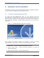
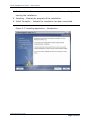
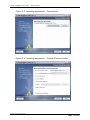
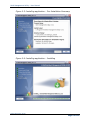
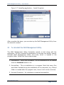
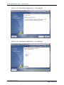
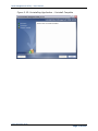
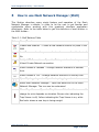
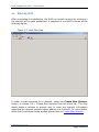
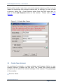
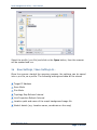
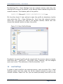
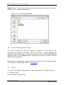
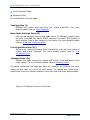
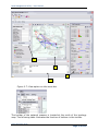
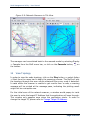
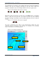
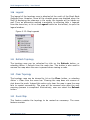
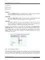
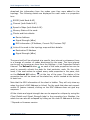
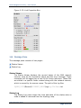
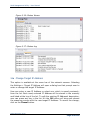
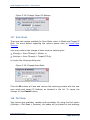
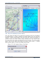
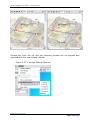
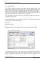
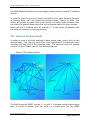
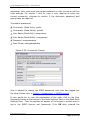
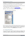
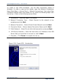
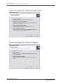
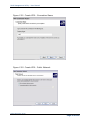
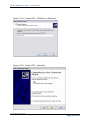
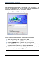
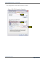
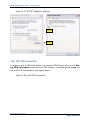
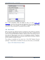
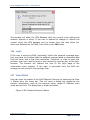
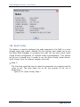
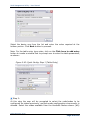
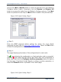
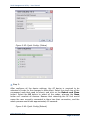
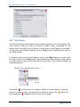
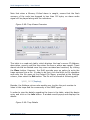
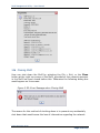
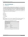
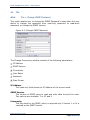
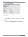
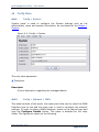
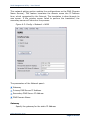
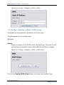
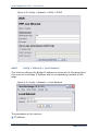
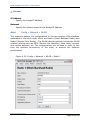
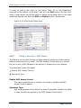
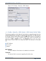
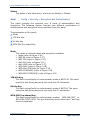
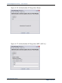
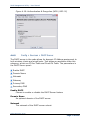
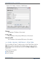
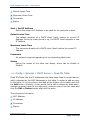
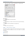
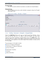
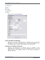
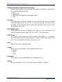
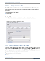
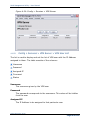
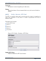
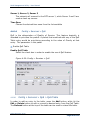
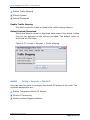
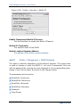
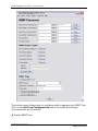
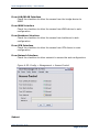
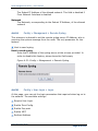
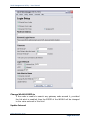
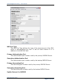
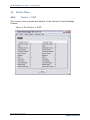
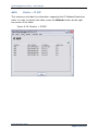
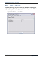
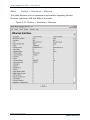
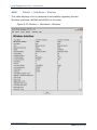
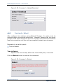
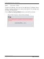


![Installation Guide: AT-TQ2450 [Rev A] (PDF Version)](http://vs1.manualzilla.com/store/data/005654085_1-f326a5d33793ff2ec849a19a13c1dba6-150x150.png)