1
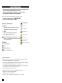
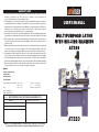
??? CARD
WARRANTY
1. KH Trading machines and tools are covered by 6/24 months warranty, starting on the date of
purchase, as described in the Civil Code (proof of purchase or invoice receipt must be
enclosed with the warranty card when making a claim).
2. This warranty does not cover defects caused by unprofessional handling, machine overloads, not
complying with instructions contained in this manual, using accessories that are not approved,
unauthorized repair, regular wear and tear and damages occurred during transport. Further, this
warranty does not cover parts and accessories such as the motor, carbon brushes, seals and
hot-air operated parts and parts that need to be changed regularly.
3. If the repair is to be found as not covered by the warranty policy, all costs including the repair and shipping to and from the repair centre will be paid by the customer, according to valid price list. See www.
4. When making a claim, you must present the warranty card, showing the date of the purchase, the
serial number of the machine, vendor stamp and signature of sales clerk, as well as the proof of
purchase receipt.
5. Warranty claim shall be made at the vendor shop where you bought your machine or you may mail
it to a service centre. The vendor is obligated to fill out the warranty card (date of sale, serial
number, vendor stamp and signature). All these information must be filled in at the time of sale.
6. The warranty period will be extended for the period of time for which the machine has been in the
service centre possession. If the repair or defect is not covered by the warranty policy, all costs including
the repair and shipping will be paid by the owner of the machine / tool. We recommend sending the
machine in its original packaging. Please, also enclose brief description of the defect with the packaging.
7. Before sending the machine for repair, clean it thoroughly. If the received machine is dirty, it may
be rejected by the service shop or you may be charged a cleaning fee.
USER'S MANUAL
MULTIPURPOSE LATHE
WITH MILLING MACHINE
AT320
SERVICE
Logistic centre Klecany
Topolová 483
250 67 Klecany
Czech Republic
Claim department phone number: 266 190 156
266 190 111
Fax:
260 190 100
http://www.KHnet.cz
Email: [email protected]
Product:
Type:
T-mobile: 603 414 975
O2:
601 218 255
Vodafone: 608 227 255
MULTIPURPOSE LATHE WITH MILLING MACHINE AT320
Serial number (product series):
AT320
Date of manufacture:
Repair centre notes:
Date of sale, stamp, signature:
AT320
Without the correctly filled warranty card or without proof of purchase receipt, including
the product type (invoice, purchase receipt) no warranty claim will be processed.
Dear customer. Thank you for purchasing equipment from KH Trading, s.r.o.
Our company is ready to offer you our services - before, during and after you buy our product.
If you have any question, comment or idea, please contact our business centre. We will do our best to address
your comment or question in timely matter.
Before first use, please read this manual carefully. It is your responsibility to study all instructions,
necessary for safe use and operation and to understand all risks that may be involved during the use
of power machines.
WARNING! Do not try to use this machine before reading this entire manual and before you know
how to handle it. Keep this manual for future reference.
Pay special attention to safety instructions. Not complying with safety rules may cause injury to the
operating person or to people standing by or it may cause damage to the machine or to the work
piece.
Pay special attention to safety notes and safety labels on the machine.
Never remove or damage them.
Please, write information such as the invoice number
and the number of the sale receipt here in this box.
DESCRIPTION
Machine description
This multipurpose machine may be used in various industrial fields, repair shops, schools and manufacturing
shops.
This machine is divided in two blocks; the lathe and the milling/drilling machine.
This combined design offers many advantages and enables you to perform turning and machining operations
on one machine. Both machines are powered independently.
After you remove the knife support, you will gain an access to the table with the "T" groves enabling you to
fasten the work piece for milling operations. The machine is equipped with longitudinal and cross feeds, as
well as with options to cut M and W threads.
It has been designed for cutting and machining of inner and outer surfaces, (conical and flat, as well as for
metric and Whitworth thread manufacturing). You may also perform drilling, machining or milling operations and
various other machining and metal cutting operations.
Number of operating persons required:1
WARNING: If your machine is not delivered with a power plug, have the appropriate
plug (compatible with your wall outlet) installed by qualified technician.
2
REPAIR AND MAINTENANCE REPORT
Report and maintenance report:
DATE
REPAIR AND MAINTENANCE REPORT
SERVICE SHOP
REVISION REPORT
TECHNICAL SPECIFICATION
The user is obligated to perform tests and revisions of electrical equipment of the machine
in accordance with valid rules and regulations. Result report:
DATE
REVISION REPORT
REVISION TECHNICIAN
Number / SIGNATURE
Lathe turning operations:
Voltage . . . . . . . . . . . . . . . . . . . . . . . . . . . . . . . . . . . . . . . . . . . . . . . . . . . . . . . . . .~400 V / 50 Hz
Power input . . . . . . . . . . . . . . . . . . . . . . . . . . . . . . . . . . . . . . . . . . . . . . . . . . . . . . . .1,100 + 370 W
Maximum cutting diameter above the bed (L) . . . . . . . . . . . . . . . . . . . . . . . . . . . . . . . . . . .∅ 320 mm
Maximum cutting diameter above the support (S) . . . . . . . . . . . . . . . . . . . . . . . . . . . . . . . .∅ 200 mm
Maximum work piece length (X) . . . . . . . . . . . . . . . . . . . . . . . . . . . . . . . . . . . . . . . . . . . . . . .750 mm
Inner chuck diameter . . . . . . . . . . . . . . . . . . . . . . . . . . . . . . . . . . . . . . . . . . . . . . . . . . . . .∅ 38 mm
Chuck cone (lathe) . . . . . . . . . . . . . . . . . . . . . . . . . . . . . . . . . . . . . . . . . . . . . . . . . . . . . . . . . .5 Mk
Tailstock cone . . . . . . . . . . . . . . . . . . . . . . . . . . . . . . . . . . . . . . . . . . . . . . . . . . . . . . . . . . . . .3 Mk
Speed (revolutions) range (lathe) . . . . . . . . . . . . . . . . . . . . . . . . . . . . . . . . . . . . . .60 - 1,600 (12) rpm
M thread pitch (degree) . . . . . . . . . . . . . . . . . . . . . . . . . . . . . . . . . . . . . . . . .0.5 - 4 (17) mm (degree)
W thread pitch (degree) . . . . . . . . . . . . . . . . . . . . . . . . . . . . . . . . . . . . . . . .11 - 40 (20) 1/" (degree)
Maximum cutting knife feed . . . . . . . . . . . . . . . . . . . . . . . . . . . . . . . . . . . . . . . . . . . . . . . . . .100 mm
Maximum feed of the cross support . . . . . . . . . . . . . . . . . . . . . . . . . . . . . . . . . . . . . . . . . . . .500 mm
Maximum longitudinal feed . . . . . . . . . . . . . . . . . . . . . . . . . . . . . . . . . . . . . . . . . . . . . . . . . .750 mm
Automatic longitudinal feed . . . . . . . . . . . . . . . . . . . . . . . . . . . . . . . . . . . . . .0.01 - 1.5 mm/revolution
Automatic cross feed . . . . . . . . . . . . . . . . . . . . . . . . . . . . . . . . . . . . . . . .0.025 - 0.34 mm/revolution
Continuous setting . . . . . . . . . . . . . . . . . . . . . . . . . . . . . . . . . . . . . . . . . . . . . . . . . . . . . . . . .NONE
Adjustable longitudinal feed . . . . . . . . . . . . . . . . . . . . . . . . . . . . . . . . . . . . . . . . . . . . . . . . . . . . .YES
Adjustable cross feed . . . . . . . . . . . . . . . . . . . . . . . . . . . . . . . . . . . . . . . . . . . . . . . . . . . . . . . . .YES
Tailstock range . . . . . . . . . . . . . . . . . . . . . . . . . . . . . . . . . . . . . . . . . . . . . . . . . . . . . . . . . . .80 mm
Number of uni chuck jaws . . . . . . . . . . . . . . . . . . . . . . . . . . . . . . . . . . . . . . . . . . . . . . . . . . . . . . . .3
Fastening diameter of the uni chuck outer/inner (Ui/o) . . . . . . . . . . . . . . . . . . . . . . . . .∅ 160/200 mm
Speed (revolutions) setting (milling/drilling machine) . . . . . . . . . . . . . . . . .260 - 2,620 (4) rpm (degree)
Head tilt angle . . . . . . . . . . . . . . . . . . . . . . . . . . . . . . . . . . . . . . . . . . . . . . . . . . . . . . . . . . . . . . .60
Table dimensions . . . . . . . . . . . . . . . . . . . . . . . . . . . . . . . . . . . . . . . . . . . . . . . . . . . .280 × 130 mm
Spindle cone (milling/drilling machine) . . . . . . . . . . . . . . . . . . . . . . . . . . . . . . . . . . . . . . . . . . . .3 Mk
Max. drill diameter . . . . . . . . . . . . . . . . . . . . . . . . . . . . . . . . . . . . . . . . . . . . . . . . . . . . . . .∅ 16 mm
Fine spindle feed . . . . . . . . . . . . . . . . . . . . . . . . . . . . . . . . . . . . . . . . . . . . . . . . . . . . . .200/60 mm
Spindle set out . . . . . . . . . . . . . . . . . . . . . . . . . . . . . . . . . . . . . . . . . . . . . . . . . . . . . . . . . . .180 mm
Maximum distance between the spindle and the table . . . . . . . . . . . . . . . . . . . . . . . . . . . . . . .265 mm
Overall dimensions (l x w x h), excluding the base . . . . . . . . . . . . . . . . . . . . .1,500 × 625 × 1,200 mm
Gross weight . . . . . . . . . . . . . . . . . . . . . . . . . . . . . . . . . . . . . . . . . . . . . . . . . . . . . . . . . . . . .400 kg
The accuracy of instructions, graphs and information contained herein, depends on the printing date. Due to
continuous product improvement, the manufacturer reserves the right to change technical parameters of the
product, without prior customer notification.
3
???
SAFETY PRECAUTIONS
• This device may be used by a qualified person, 18 years or older who has been
trained in work and environmental safety procedures.
• Any person using this equipment must possess a medical certificate
demonstrating his eligibility to operate this equipment.
We recommend placing work safety regulations notices at your workshop:
• "Prevent most common injuries" - MILLING MACHINES
• "Prevent most common injuries" - LATHES
Symbols used in this manual
Warning!
This symbol informs you about the risk of personal
injury or damage to the machine or materials.
Caution!
You are using electrically powered machine!
Risk of injuries by electrical current.
Risk of being caught by spinning machine parts!
Caution! Loose clothing or body parts may get caught
by moving machine parts.
Warning!
Danger of damage.
In case of fire do not use water
or foam fire extinguishers
Use protective gloves
Use face protective shield
Danger of having fingers cut
Caution! Electrical equipment
Read manual before use
Caution! Danger of being caught
by machine moving parts
Before use, close the protective cover
Note:
Additional information.
Use personal protective gear.
General instructions
• Make sure you know how to control your tool or machine and that you are familiar with its operating
procedure. Know the hazards that may occur, if not used correctly.
• If other person is using this machine make sure that he knows how to safely operate this equipment and
that he is familiar with hazards and risk that may occur, if not used correctly.
• Pay special attention to safety notes and safety labels on the machine. Do not remove or damage them.
If the warning label becomes unreadable, please contact your vendor.
• Dirty and disorganized workplace may cause accidents.
• Never work in poorly lit, narrow or too crowded rooms. Always keep stable posture.
• Maintain your tools clean and in safe working conditions.
• Handles must be kept free of grease and dirt.
• Make sure no children, unauthorized persons or animals have access to your workshop.
4
72
AT320-09-042
Right transmission cover
73
M8×40 GB4141.14-84
Long socket ball grip
74
8×50×12 GB4141.15-84
Handle lever
75
M4×16 GB67-76
Screws with cylindrical head and groove
76
M8 GB923-76
Enclosed nut
77
AT320-09-024
Adjustment washer
78
AT320-09-025
Handle housing
79
AT320-09-026
Calibrated dial
80
AT320-09-043
Elastic lamella
81
M4×8 GB818-85
Screw
82
AT320-09-045
Handle lever
83
AT320-09-027
Spring seat
84
AT320-09-033
Fastening base
85
AT320-09-028
Secondary shaft
86
5×10 GB1096-72
Flat spline
87
M5×10 GB819-85
Screw
•
•
•
•
•
•
•
•
•
•
•
•
•
•
•
•
•
•
•
•
•
Use only for purposes for which it has been designed.
Use personal protective gear such as safety goggles, ear protection, respirator, safe working shoes etc.
Do not overreach, use both hands.
Never work under the influence of alcohol or other drugs.
Do not use the machine/tool if you feel dizzy or week.
Any modifications or improvements to the machine are strictly prohibited. DO NOT USE if you discover
bent part, crack or other damage.
Never perform any maintenance during operation.
If you see any unusual sign or hear any strange sound, switch off the machine immediately.
Do not forget to remove all wrenches and screwdrivers from the machine after use.
Before use, make sure all screws are tightened securely.
Perform maintenance regularly. Before use make sure the machine is in good working conditions
and without any damage.
Use only original spare parts during repairs.
Using extension pieces or accessories not approved by the manufacturer may cause injuries to
the operating personnel.
Use suitable tool for particular type of work. Do not overload tools, accessories or the machine. For large
work volume use more powerful machine.
Do not overload your device. Measure the work load in such way, so it could be done with comfortable
speed. Damages due to machine overload are not covered by the warranty policy.
Do not expose to extremely high temperature or direct sunlight.
This machine is not designed for use in humid environments or under water.
If you are not using your machine, store it in a dry and safe place, out of reach of children.
Before use make sure that all safety elements work correctly and efficiently. Make sure all moving parts
are in good working conditions.
Before use make sure that no part is cracked or stuck, Make sure all parts are attached and assembled
as designed. Beware of all other conditions that may have a negative effect on the proper functioning of
your machine.
If not stated otherwise in this manual, all damaged parts and safety elements must be repaired
or changed.
Assembly
• Do not use the machine unless completely assembled.
Electrical equipment
• Observe all basic safety rules when using electrical equipment to prevent risk of fire, injuries by
electrical shock and other hazards. Before using this device, read this manual entirely and follow all safety
instructions.
• Make sure the power cable plug is plugged into the correct wall outlet. The voltage in the wall outlet must
be the same as shown on the specification label to prevent damage to the electric motor. Too low voltage
will not provide your machine with enough power.
• Before connecting the machine to the wall outlet make sure that the main switch is in the "OFF" position.
When you finished your work, disconnect the power plug from the wall outlet and switch off the main
switch.
28
5
• Never carry electrical tools and appliances by their power cord. When disconnecting the plug from the
wall outlet, never pull the cable by its cord.
• Protect the power cable from high temperatures, oils, paint thinners and make sure that the cable is not
hanging over sharp edges.
• Inspect the power cable regularly. If damaged have it replaced by qualified technician. Inspect extension
cables regularly. If damaged, have it replaced.
• If you need to use an extension cable, use cable with appropriate power rating. Use only completely
unwound. Inspect extension cables regularly. Damaged cable must be repaired or changed immediately.
• Before performing any maintenance, repair or adjustment, switch off the main switch and disconnect the
power cable from the wall outlet.
• Make sure no one may switch you machine incidentally on. Do not keep your fingers close to the main
switch, unless absolutely necessary.
• If you mount your machine to the work table, release the safety button after installation.
• Do not use in environments where explosives are stored or used (paint shops, warehouse with
flammables etc.).
• Do not use in humid environments or if wet.
Rotary tools/machines
• Always wear suitable work clothing (do not wear loose clothing, ties, jewellery etc.). Long hair must be
covered and tied up behind you head. Do not wear worn out working shoes. Sleeves must be rolled up.
Loose clothing or body parts may get caught by moving machine parts.
• Do not remove safety covers. Make sure the operating personnel is well-protected.
• Do not touch or come close with moving machine parts during work. Keep your hands away from moving
and spinning machine parts.
Machining and turning operations
• Always securely fasten the work piece on the work table using appropriate clamping equipment or vise.
Do not hold the work piece in your hands during work. Use both hands to hold the handles of the
machine/tool.
• Do not overreach. Maintain stable posture on both legs. That way you will not be thrown out of balance in
case of a reverse impact.
• Keep your tools clean and sharp.
• When changing tools or during maintenance, follow safety instructions.
• To feed or move the work piece use appropriate extension tool.
• Make sure the work piece complies with required technical parameters and that it is securely fastened.
• Use extra caution when releasing the work piece from the fastening device.
Drilling
• Make sure the work piece is properly fastened to the work table and secured against turning during
drilling.
• Before switching your machine on make sure the chuck is turning in the right direction, based on the
used tool.
6
35
5×25 GB117-86
36
AT320-09-041
Conical stud
Large shifting fork
37
AT320-09-029
Shaft socket
38
AT320-09-030
Stopper screw
39
AT320-09-031
Adjustment socket
40
AT320-09-32
Safety nut
41
AT320-09-001A
Drilling/milling spindle box
42
M8×18 GB79-85
Screw with inner hexagonal head slot
43
JY7124 370W
Motor
44
10 GB97.2-85
Regular washers
45
M10 GB6170-86
Hexagonal nut
46
AT320-09-031
Shifting fork shaft
47
AT320-09-039
Small shifting fork
48
M8×20 GB70-76
Screws with inner hexagonal head slot
49
AT320-09-002
Engine assembly plate
50
M6×20 GB70-76
Screws with inner hexagonal head slot
51
AT320-09-004A
Input shaft
52
AT320-09-005
Flat spline
53
M2×5 GB818-85
Screw
54
40 JB/GQ0251-89
Bearing socket
55
50207 GB277-89
Radial ball bearing
56
17 GB894.1-86
Outer safety ring
57
AT320-09-003A
Double toothed gear
58
60201 GB278-89
Radial ball bearing
59
12 GB894.1-86
Outer safety ring
60
12 GB894.1-86
Outer safety ring
61
32 JB/GQ0251-89
Bearing socket
62
50207 GB277-89
Radial ball bearing
63
AT320-09-015A
Toothed gear
64
AT320-09-016
Socket spacer
65
AT320-09-006
Toothed gear
66
AT320-09-007
Toothed gear
67
AT320-09-017
Middle shaft
68
5×55 GB1096-72
Flat spline
69
60201 GB278-89
Radial ball bearing
70
12 GB894.1-86
Outer safety ring
71
M5×16 GB70-76
Screws with inner hexagonal head slot
27
Milling
• Make sure the material is fed to the machine in the correct direction that is, against the directions of the
spinning cutting head.
Drilling/milling head
Position
Dimensions
Name
1
35 GB894.1-86
Outer safety ring
2
207 GB276-89
Cylindrical bearing
3
AT320-09-020
Shaft socket
4
AT320-09-021A
Toothed gear
5
50207 GB277-89
Radial ball bearing
6
72 JB/GQ0251-89
Bearing socket
7
35 GB894.1-86
Outer safety ring
8
AT320-09-018
Levelling ledge
9
8×45 GB1097-79
Flat spline
10
M3×8 GB67-85
Round head setting screw
11
M4×8 GB68-85
Sink head screws with groove
12
M30×1.5 GB812-88
Round nut
13
2007106 GB297-84
Conical bearing
14
AT320-09-008A
Spindle socket
15
D2007107 GB297-84
Conical bearing
16
AT320-09-022
T - wedge
17
AT320-09-009A
Drilling/milling spindle
18
45 JB/GQ0324-89
Felt ring
19
M4×12 GB71-85
Setting screws with conical tip
20
AT320-09-013
Bearing cover
21
AT320-09-034
Handle housing
22
1×7×12 GB2089-80
Spring
23
AT320-09-035
Connecting screw
24
5×50 GB117-86
Conical stud
25
AT320-09-044
Positioning handle
26
BM8×40 GB4141.14-84
Long socket round grip
27
M4×8 GB67-85
Round head setting screw
28
5×45 GB119-86
Cylindrical stud
29
AT320-09-036
Positioning plate
30
M5×16 GB70-76
Screws with inner hexagonal head slot
31
4×20 GB117-86
Conical stud
32
AT320-09-042
Left transmission cover
33
AT320-09-040
Shifting fork shaft
34
AT320-09-038
Swivelling gate
26
Lathe turning operations
• Do not allow unauthorized persons to stand close to your machine to prevent injuries by spinning work
piece.
• Make sure that the operating person wears personal protection gear to prevent injuries from flying and
spinning metal cuts and sawdust.
• Do not carry objects in your upper pocket. Do not wear jewellery. Always place tools and measuring
equipment on the same place.
• The operating personnel must wear working cloth and must not wear gloves. Long hair must be tied
behind your head to prevent injuries by spinning parts.
• Stairs for the operating personnel must be equipped with skid-proof surface. Always keep secure and
stable position during work. Do not lean over and above the machine. Do not overreach.
• Do not work with work pieces that do not comply with the dimensioning requirements and with the
machine specifications.
• Make sure that the work piece and the cutting tools are securely fastened. After you have fastened
the cutting tool, make sure to remove all wrenches and other fastening tools from the spindle or chuck.
Before starting the machine, make sure the operating personnel always removes all wrenches,
screwdrivers and other fastening tools from the machine.
• Make sure to choose and use correct tools. Work piece must be always securely fastened. Do not touch
the work piece.
• Perform maintenance, adjustment or tool changing only if the machine is switched off and the spindle has
completely stopped.
• Never leave the running machine unattended. You may leave the machine only if it is switched off and the
chuck or spindle came to a complete stop.
• Also beware of other risks and dangerous situations that my occur during operation.
Power equipment
• If your machine is equipped with depressed springs, use suitable device to release them slowly and
safely.
7
ASSEMBLY
???
• Make sure no part is left inside the packaging box before throwing the packaging materials out. If so, take
it out and install it. Use the part listing for check-up and the installation drawing for guidance.
• We recommend to use lifting method shown on picture 2 or you may use forklift. Level the machine
during transport and installation to prevent flipping over. After you have balanced the machine, you may
turn the drilling and milling head by 180°.
Machine lifting
Follow the procedure shown on picture 3. Use water/air level to align the guide
and small stand. Mount the machine to the base with bolts. The machine base
may be manufactured according to special customer requirements.
• Follow the assembly procedures shown on the picture. Use water/air level to align the guide and small
stand. Mount the machine to the base with bolts.
• You may use the machine only if it is securely mounted and fastened. Otherwise dangerous vibrations may
occur during work.
• Before starting the machine make sure that the voltage in the wall outlet (or the power source) is the same
as shown on the specification label of your machine. Also make sure that the power cable is equipped
with grounding pin. Your machine must be properly grounded to prevent injuries by electric shock.
• Do not use the machine in harsh environments, do not install it on a wet place and protect it from rain.
Use only in dry environments. Humid environment may cause corrosion of metal parts or may damage
the electric system of your machine.
8
Bed/stand
Position
Dimensions
Name
1
AT320-00-007
Pedestal
2
8×35 GB117-86
Conical stud
3
12 GB93-87
Washer
4
M12×40 GB70-85
Screw with inner hexagonal head slot
5
12 GB93-87
Washer
6
M12×55 GB70-85
Screw with inner hexagonal head slot
7
AT320-00-001
Stand
8
AT520-01-004
Head of column
9
M6×20 GB70-85
Screw with inner hexagonal head slot
10
8106 GB301-84
Bearing
11
AT320-00-004
Upper column housing
12
30 GB858-88
Washer
13
M30×1.5 GB812-88
Round nut
14
M10 GB923-88
Nut
15
B12×100 GB4141.22-84
Manual wheel
16
8103 GB301-84
Bearing
17
4×12 GB1096-79
Flat spline
18
AT320-00-005
Height adjustment guiding screw
19
17 GB894.1-86
Outer safety ring
20
M6×25 GB70-85
Screw with inner hexagonal head slot
21
AT520-01-006
Height adjustment nut
22
AT320-00-002
Revolving housing
23
M10×45 GB5783-86
Screws
24
AT320-00-003
Screw
25
AT320-00-008
Adjustment socket
26
AT320-00-009
Self-cutting screw
27
AT300-00-123
Handle housing
28
3×25 GB117-86
Conical stud
29
M8×40 GB4141.15-84
Handle lever
30
M8×40 GB4141.14-84
Ball hand grip
25
???
OPERATION
72
CQ9332A-01-008
Cam
73
M4×6 GB71-85
Setting screws with groove and conical tip
74
CQ9332A-01-013
Rack poles
75
10 GB93-87
Washer
76
M10×40 GB70-85
Screws with inner hexagonal head slot
77
M10×35 GB70-85
Screws with inner hexagonal head slot
78
CQ9332-00-016
Cover
79
M5×10 GB70-85
Screws with inner hexagonal head slot
• Caution: If you are using your machine in low temperature, let it run for about 20 minutes at 160 rpm to
warm it up.
• After you have assembled your machine you must remove the anti-corrosion coatings with paraffin oil
from the guides, columns, support, exchangeable gears and pulleys. Then you must lubricate it with proper
lubrication oil or grease.
Control buttons and elements
1.
2.
3.
4.
5.
6.
7.
9.
10.
11.
12.
13.
24
Transmission cover star-grip wheel
5 pin power cable
Emergency stop button
Power on control light. Indicating that the
machine is connected to the power source.
Main switch
Speed/rpm gear selector (lathe). You may
switch gear only if the engine is stopped.
Longitudinal feed direction switch.
Manual wheel of the longitudinal support.
Milling plate
Manual cross feed wheel of the knife head and
small stand.
Knife head safety and release handle It is used
during tool changing.
Manual wheel for fine longitudinal feed control of
the knife head.
14.
15.
16.
17.
18.
19.
20.
21.
22.
23.
24.
25.
ON/OFF switch of the longitudinal feed.
ON/OFF switch of the cross feed.
ON/OFF switch of the cross feed.
Locking handle of the tip socket.
Tailstock locking handle.
Manual wheel of the tip socket feed control.
Adjusting screw. Used for concentric aligning of
the revolving tip centre with the chuck spindle.
Setting of the drilling/milling head position.
Spindle gear shifting lever.
Drilling/milling head engine switch.
Fine vertical feed of the drilling/milling head.
Manual wheel for drilling/milling head lifting.
9
Electric control of machine power drives.
Lathe
Red round button: Stop button - emergency stop.
Stops the entire machine.
Green round control light: Indicates power on - main
switch in the ON position.
Green round button: main switch.
Red switch (in the lower middle part): switches
on/off the cooling fluid pump.
Milling/drilling spindle
35
M10 GB923-88
Nut
36
CQ9332-05-008
Cross feed guiding screw housing
37
M8×40 GB70-85
Screws with inner hexagonal head slot
38
CQ9332-01-007
Base platform
39
CQ9332-5-005
Front platform
40
CQ9332A-05-002
Stand
41
HA300-05-042
Grooved plate - in left rear side
42
HA300-05-044
Grooved plate - in left front side
43
6 GB1155-79
Oil lubrication cap
44
AT320-01-009
Cross nut
45
AT320-00-006
Work table
46
AT320-01-002
Longitudinal feed screw
47
CQ9332A-01-010
Right pedestal
48
6 GB1155-79
Oil lubrication cap
49
M8×20 GB70-85
Screws with inner hexagonal head slot
50
CQ9332-01-010
Socket
51
CQ9332-02-011
Guiding studs
52
AT520-03-106
Guiding studs
53
CQ9332A-01-012
Socket
54
5×30 GB117-86
Conical stud
55
M8×60 GB70-85
Screws with inner hexagonal head slot
56
M5×10 GB71-85
Setting screws with groove and conical tip
57
5×35 GB119-86
Cylindrical stud
58
CQ9332A-01-007
Adjustment handle housing
59
CQ9332A-01-004
Control socket
60
M10×32 GB4141.12-84
Ball handle socket
61
M6×12 GB70-85
Screws with inner hexagonal head slot
62
CQ9332A-01-009
Pedestal
63
CQ9332A-01-006A
Shaft socket
64
CQ9332A-01-003A
Control pole
65
M8×8 GB73-85
Setting screw with flat tip
66
0.5×6×15 GB2089-80
Spring
67
6 GB307-88
Steel ball
68
M8×15 GB71-85
Setting screws with groove and conical tip
69
0.5×6×25 GB2089-80
Spring
70
4×25 GB117-86
Conical stud
71
AT520-03-014
Connecting socket
Black switch. Switches on/off the spindle engine - seen on the left side of the picture.
10
23
PART???
LISTING
Column
Gear shifting chart (lathe)
Position
Dimensions
Name
1
CQ9332A-01-001
Bed/stand
2
CQ9332-01-003
Rack poles
3
6×18 GB117-86
Conical stud
4
M8×16 GB70-85
Screws with inner hexagonal head slot
5
CQ9332-01-005
Block
6
CQ9332-05-015
Washer
7
M5×12 GB68-85
Screw
8
M6×25 GB75-85
Screw
9
M6 GB6170-86
Hexagonal nuts
10
M6×35 GB70-85
Screws with inner hexagonal head slot
11
8 GB1155-79
Oil lubrication cap
12
6×40 GB117-86
Conical stud
13
M6×30 GB70-85
Screws with inner hexagonal head slot
14
M6×45 GB70-85
Screws with inner hexagonal head slot
15
M6×40 GB5782-86
Screws with hexagonal head
16
HA300-05-044
Grooved plate - in right front side
17
M5×10 GB818-85
Screws with sink cross-conical head
18
CQ9332-01-008
Block
19
M8×20 GB79-85
Setting screws with inner hexagon and conical tip
20
M8 GB6170-86
Hexagonal nuts
21
HA300-05-041
Grooved plate - in right front side
22
CQ9332-05-027
Chain tackle gear
23
CQ9332-05-006
Toothed gear
24
AT320-05-004
Cross feed guiding screw
25
5×16 GB1096-79
Flat spline
26
4×18 GB1096-79
Flat spline
27
8201 GB301-84
Cylindrical bearing
28
6 GB1155-79
Oil lubrication cap
29
M6×16 GB70-85
Screws with inner hexagonal head slot
30
5×20 GB117-86
Conical stud
31
CQ9332-05-024
Dial
32
AT300-03-139
Spring lamella
33
AT300-03-138
Dial socket
34
12×40 GB4141.9-84
Handles with socket
22
Manual machine control
Thread cutting:
• During thread cutting make sure that the positions of the toothed gears are the same as the positions of
the shifting levers to ensure correct thread pitch.
• The relationship between the gear and the lever position is shown in the chart. During operation follow the
instructions on the transmission label or in the following chart.
11
Drilling/milling head
12
21
Bed/stand
Longitudinal feed direction and activation.
See the lever above the cooling fluid pump switch.
WARNING: The automatic feed is not equipped with end
switch or a stopper. If the feed hits the end, it will damage
the machine.
Shifting gears during drilling and milling operations.
Vertical feed of the drilling/milling head
Rough - manual wheel (seen at the rear of the picture)
Fine - three-arm head
Knife holder with cross and
longitudinal feed control
WARNING: The automatic feed
is not equipped with end switch
or a stopper. If the feed hits
the end, it will damage the
machine.
20
13
Column
ELECTRICAL DRAWING
???
CONNECTION
3 phase 5 lead plug
Fork F551
MOTOR
Recommended plug
connection
Electrical parts on
the machine
MOTOR
TROUBLESHOOTING
• Make sure that the work piece dimensions are within the specifications shown below.
• If you cannot switch the engine on and the power source is ok, check if the switch is working correctly.
For example; check the transmission switch. First check the power plug fuse. Sometimes the defect is
caused by the engine breakdown due to improper lubrication, overloads, not sufficient free play etc.
MAINTENANCE
•
•
•
•
•
Keep your tools clean. Dirt may enter the inner mechanism of your machine and cause damage.
Do not use aggressive cleaning solution or paint thinners to clean the machine.
Clean plastic parts with cloth dipped in soup water.
Clean and lubricate metal surfaces with a cloth dipped in paraffin oil.
If you are not using your machine, lubricate it with suitable grease and store it in a dry place to prevent
corrosion.
• To lower friction in the dovetail groove of the small stand support, small steel pieces are placed inside
the groove. They are correctly set at the factory. After certain time, the gap may get bigger or smaller.
Set their position according to your requirements.
14
19
DETAILED PART
??? DRAWING
Renewing the position
of wedge number I
2 screws and nuts
Wedge
Drive train
Renewing the position of
wedge number II
The power drive parts are marked as follows:
1 Driving pulley
2. Changeable toothed gear
3. Changeable toothed gear
4. Changeable toothed gear
5. Changeable toothed gear
6. Driving toothed gear
7. Toothed gear
8. Toothed gear
9. Toothed gear
10. Triple and moveable toothed gear
11. Toothed gear
12. Shaft wheel
13. Shaft wheel
14. Toothed gear
15. Double and moveable toothed gear
16. Guiding screw of the knife head
17. Nut of the knife head
18. Tailstock guiding screw
18
2 screws and nuts
Wedge
Lubrication
Lubricate working surfaces with suitable grease regularly.
• Make sure to lubricate your machine during operation. Pay special to guiding surfaces. Not enough oil on
the column surface make cause severe damages.
• Recommendation: inspect your machine regularly. Have defects repaired in timely manner. That way you
eliminate other damages that may be direct result of the damages that you did not paid attention to.
• The parameters of the vertical drilling/milling feed cannot be higher than the specified values. The best
position is at 90° angle.
• Note: The contents of the manual may be changed without prior notification.
19.
20.
21.
22.
23.
24.
25.
26.
27.
28.
29.
30.
31.
32.
33.
34.
35.
36.
Tailstock nut
Longitudinal feed screw
Long divided nut
Cross guiding screw
Cross nut
Toothed gear
Toothed gear
Toothed gear
Worm gear
Worm screw
Toothed gear
Toothed gear
Toothed gear
Toothed gear
Toothed gear
Moveable toothed gear
Toothed gear
Engine pulley
• List of lubrication spots
15
Position on
picture 6
Lubrication spots
Location
Method of
lubrication
Grease type
Lubrication
period
1
Exchangeable
toothed gears, shaft
protection case
Left pedestal
Lubricate with
pressurized oil
Machine oil
One year
2
Spindle shaft
bearing (lathe)
Lathe spindle
Lubricate with
grease
Lubrication
grease
One year
3
Power drive bearing
Left pedestal
Lubricate with
grease
Lubrication
grease
One year
4
Dovetail guide,
screw
Support
Lubricate with
pressurized oil
Machine oil
Twice a day
5
Toothed gears,
toothed rack
Drilling/milling
spindle
Lubricate with
grease
Lubrication
grease
Once a month
6
Guiding screw of
the knife head,
surface guides
Knife head
Lubricate with
pressurized oil
Machine oil
Twice a day
7
Longitudinal feed
screw
Feed screw
Lubricate with
pressurized oil
Machine oil
Twice a day
8
Bed/stand guide
Bed/stand
Lubricate with
pressurized oil
Machine oil
Twice a day
9
Tip socket
Tailstock
Lubricate with
pressurized oil
Machine oil
Twice a day
10
Bearing case
Tailstock
Lubricate with
pressurized oil
Machine oil
Twice a day
11
Bearing contact
surface
Bed/stand
Lubricate with
pressurized oil
Machine oil
Twice a day
12
Cross nut,
guiding screw
Small support
Lubricate with
pressurized oil
Machine oil
Twice a day
13
Bearing case
Small support
Lubricate with
pressurized oil
Machine oil
Twice a day
14
Power drive bearing
Guide screw
housing
Lubricate with
grease
Lubrication
grease
Six times per
year
15
Counter gear
Transmission
Lubricate with
pressurized oil
Machine oil
Twice a day
16
Bearing
Driving pulley
Lubricate with
grease
Lubrication
grease
Once a day
17
Toothed gear
Drilling/milling
spindle
Lubricate with
grease
Lubrication
grease
Once a year
18
Elevator guide
screw, nut
Drilling/milling
spindle
Lubricate with
pressurized oil
Machine oil
Twice a day
19
Column
Drilling/milling
spindle
Lubricate with
pressurized oil
Machine oil
Once a day
16
Note:
• We recommend using lubrication grease with consistency number 3. Applies to the "Lubrication grease"
in the chart.
• Use machine oil SAE 20. Applies to the "Machine oil" in the chart.
• All lubricated parts must be cleaned and lubricated. Follow the support oil changing periods. Refill the oil
up to the marking.
• Follow the lubrication periods recommended in the chart.
DISPOSAL
• Used oils and cooling fluids must be disposed off in accordance with the applicable Waste management
law.
When the operational life of your device is over, dispose off it in accordance with valid rules and regulations.
Your product is made of metal and plastic parts that may be recycled when separated.
1. Disassemble all parts.
2. Separate all parts according to the material they are made of (e.g. metals, rubber, plastics, etc.).
Take the separated parts to the recycling facility near you for further processing.
3. Electrical waste (used electrical power tools, electric motors, recharging equipment, electronics,
accumulators, batteries etc.).
Dear customer. In accordance with the valid regional rules and regulations describing the management of
electrical waste, electrical waste is considered dangerous.
Disposal of electrical waste must be therefore handled as dangerous waste in accordance with waste
management rules valid in the state you are in.
It is prohibited to mix electrical waste with regular household waste.
You may return your used electrical appliance to a recycling facility near you. More information about
electrical and dangerous waste disposal may be obtained from your local authority or from the Internet.
CAUTION
If the machine breaks down, send it back to the vendor for quick repair.
Please, enclose brief description of the defect. That makes repair easier. If the machine is still covered by
warranty, enclose the warranty card and proof of purchase receipt. After the warranty period expires, we
repair your machine for a special price.
To prevent possible damages during shipping, packed the machine carefully or use the original packaging
material. We are not liable for shipping damages due to incorrect packaging of your machine. If making
a claim at the shipping company the level and method of packaging plays a major role during claim evaluation
process.
Note: Pictures and contents in this manual may slightly differ from the actual product or accessories.
It is due to continuous improvement of our products. Such small differences have no effect on the product
functionality.
17