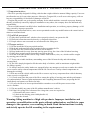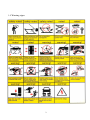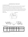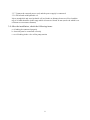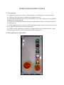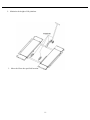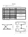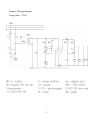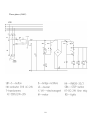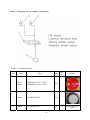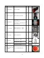
1
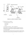
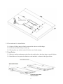
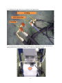
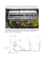
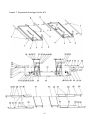
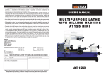
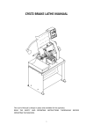
QJYJ30-ZW Scissor Vehicle Lift
Operation Manual
Instructions are part of the product, please place where you
can always find for easy reference. Read the instructions
carefully before the start of installation, operation and
Tongrun lift and its distributors are not liable for any
accidents caused by misuse, abuse, alterations on parts,
which not authorized by them.
INDEX
1. Important safety instructions…………………………………...………..1-2
1.1 Important notices
1.2 Qualified personnel
1.3 Danger notices
1.4 Warning signs
2. Overview of the lift…………………………..…………………………..3-4
2.1 General descriptions
2.2 Technical data
2.3 Construction of the lift
3. Installation instructions……………………..……………………………4-8
3.1 Preparations before installation
3.1.1 Tools and equipments needed
3.1.2 List for parts checking
3.1.3 Ground conditions
3.2 Precautions for installation
3.3 Installation
3.4 Items to be checked after installation
4. Operation instructions……………….…………………………………..9-11
4.1 Precautions
4.2 Descriptions of control box
4.3 Operating instructions
5. Trouble shooting……………………………….……………………….....12
6. Maintenance……………………………………………………………13-14
7. Annex……………………..…………………………………………....15-24
Annex 1
Annex 2
Annex 3
Annex 4
Annex 5
Annex 6
Annex 7
Packing list of the whole lift
Overall diagram
Hydraulic working system
Wiring diagram
Diagram for air supply connection
Spare parts list
Separated drawings for the lift
IMPORTANT SAFETY INSTRUCTIONS
1.1 Important notices
·The lift is specially designed for lifting vehicles that weighs within its outmost lifting capacity. Users are
not allowed to use it for any other purposes. Otherwise, Tongrun lift, as well as our sales agency, will not
bear any responsibility for accidents or damages of the lift.
·Tongrun lift provide one-year's quality warranty for the whole machine. Personal or property damage
directly or indirectly caused by improper installation or any abuse, the company does not undertake any
responsibility.
·Please read this manual carefully before installation and operation, to avoid any property damage, or life
injury caused by improper operation.
·Without our professional advice, users are not permitted to make any modification to the control unit or
whatever mechanical unit.
1.2 Qualified personnel
1.2.1 Only these qualified staff, who have been properly trained, can operate the lift.
1.2.2 Electrical connection must be done by a competent electrician.
1.2.3 People who are not concerned are not allowed in the lifting area.
1.3 Danger notices
1.3.1 Do not install the lift on any asphalt surface.
1.3.2 Read and understand all safety warnings before operating the lift.
1.3.3 Do not leave the controls while the lift is still in motion.
1.3.4 Keep hands and feet away from any moving parts. Keep feet clear of the lift when lowering.
1.3.5 Only these properly trained personnel can operate the lift.
1.3.6 Do not wear unfit clothes such as large clothes with flounces, tires, etc, which could be caught
by moving parts of the lift.
1.3.7 To prevent evitable incidents, surrounding areas of the lift must be tidy and with nothing
unconcerned.
1.3.8 The lift is simply designed to lift the entire body of vehicles, with its maximum weight within
the lifting capacity.
1.3.9 Always insure the safety latches are engaged before any attempt to work near or under the vehicle.
Never remove safety related components from the lift. Do not use if safety related components are
damaged or missing.
1.3.10 Do not rock the vehicle while on the lift or remove any heavy component from vehicle that may
cause excessive weight shift.
1.3.11 Check at any time the parts of the lift to ensure the agility of moving parts and the performance
of synchronization. Ensure regular maintenance and if anything abnormal occurs, stop using the lift
immediately and contact our dealers for help.
1.3.12 Lower the lift to its lowest position and do remember to cut off the power source when
service finishes.
1.3.13 Do not modify any parts of the lift without manufacturer’s advice.
1.3.14 If the lift is going to be left unused for a long time, users are required to:
a. Disconnect the power source;
b. Lubricate the moving parts with hydraulic oil;
c. Empty the oil tank.
Warning: lifting machine is of high risk products. Improper installation and
operation, or modification on the parts without authorization, are likely to cause
damage to the operator, even resulting in death. Read the instructions carefully
and strictly operate the lift according to the requirements.
1
1.4 Warning signs
2
OVERVIEW OF THE LIFT
2.1 General descriptions
QJYJ30-ZW scissor lift is equipped with the trailer-mounted control system which is convenient for
speedy repair in outdoor. The scissor lift is suitable for hoisting small and medium-sized vehicles
which is below 3.0 ton to conduct repair and maintenance of various types of vehicles.
Power unit is driven by hydraulic system. And hydraulic oil will be driven to the hydraulic cylinder by
gear pump, which drive piston rod to lift vehicle. The machine is equipped with mechanical safety lock
and both the left and right side of the bottom plate is fixed with a preventing overturn, this makes the
machine safer.
Safety structure:
2.2 Technical data
Model
Lifting
capacity
Lifting
time
Fall
time
Lifting
height
Total
weight
Power supply
QJYJ30-ZW
3000KG
<50s
>20s
1000mm
480KG
220V,Single-phase
380V,three-phase
2.3 Construction of the lift
3
INSTALLATION INSTRUCTIONS
3.1 Preparations before installation
3.1.1 Tools and equipments
·Electrical drill
·Open wrenches
·Screw drivers
·Hammer
3.1.2 List
needed
for parts checking --- Annex 1(Packing list)
Open the package, refer to the attachment 1 (packing list), check all parts, if any parts
missing happen, please contact the dealer or manufacturer immediately. In this case, you
should not continue installation. Otherwise Tongrun lift and distributors are not liable.
3.1.3 Ground
conditions
The lift should be fixed on a smooth and solid concrete ground with its strength more than
3000psi, tolerance of flatness less than 5mm and minimum thickness of 200mm. In addition,
newly built concrete ground must undergo more than 28days’ cure and reinforcement.
4
3.2 Precautions for installation
3.2.1 Joints of oil hose must be firmly connected in order to avoid leakage.
3.2.2 All bolts should be firmly screwed up.
3.2.3 Do not place any vehicle on the lift in the case of trial running.
3.3 Installation
3.3.1 Remove machine and pump station from the packing box, then drag them to specified place
3.3.2 Install the two feet protection fenders on the machine, as shown in the figure below.
5
3.3.3 Indentify the pipe and wires, as shown in the figure below.
3.3.4 Connect two pieces of tubing to pumping stations, each side has 1 port, two pieces of
tubing can be freely arranged on either side. As shown in the figure below.
6
3.3.5 Connect the limit switch wiring to the electrical box inside, as shown in the figure below:
connect 01 wiring with 01 connecting column, connect 03 wiring with 03 connecting column
3.3.6 Connect the power supply plug in accordance with the electrical schematic diagram, then
connect the compress air (the range of air pressure is between 1.0 and 1.5 kg/cm2) to air inlet of
pump station oil-water separator, and then connect security lock pipe to the air outlet of
pneumatic solenoid valve of pumping station.
7
3.3.7 Connect the external power cord, and the power supply is connected.
3.3.8 Fill oil tank with hydraulic oil.
Inject enough 46# anti-wear hydraulic oil in oil tank, the distance between oil level and the
top of oil tank should be in the range which is between 10 and 30 mm (stock rod which is on
oil drum cove measures distance)
3.4 After the installation, check the following items:
a. oil tubing be connected properly
b. electrical parts be connected correctly
c. no oil leaking in the valve of the pump station
8
OPERATION INSTRUCTIONS
4.1 Precautions
4.1.1 Check all the joints of oil hose. Only when there is no leakage, the lift can start work.
4.1.2 The lift, if its safety device malfunctions, shall not be used.
4.1.3 The machine shall not lift or lower an automobile if its center of gravity is not positioned
midway of the rising platforms.
4.1.4 Operators and other personnel concerned should stand in a safety area during lifting and
lowering process.
4.1.5 When platforms being raised to the desired height, switch off the power at once to prevent
any wrong operation done by unconcerned people.
4.1.6 Make sure the safety locks of the lift are engaged before start working under the vehicle
and no people under the vehicle during lifting and lowering process.
4.2 Descriptions of control box
9
4.3 Operation instructions
Raise the lift:
1.Make sure that you have read and understood the operation manual before operation.
2.Drive and park the vehicle midway between two platforms.
3.Place the four rubber pads under the prop-points of the vehicle and ensure car’s gravity have
fallen on the rubber pads.
4.Press the UP button on the control box until rubber pads have touched the prop-points of vehicle
5.Keep on pressing the UP button to lift the vehicle a bit higher from the ground and check
again if the vehicle is in a safe position.
6.Having raised the vehicle to the required height, press the “lock” button to make the mechanical
safety lock be engaged and then press the “emergency stop” and check again the stability of the
vehicle before performing maintenance or repair work.
Lower the lift:
1.Open the emergency stop switch.
2.Press and hold DOWN button, the platform will raise a certain height, in order to open the
insurance part, then the platform begin to descend.
3.The machine is equipped with safety warning device, it’s normal to hear alarm voice throughout
the descending process.
4.Drive away the car when platform be lowed to the minimum height.
5.Shut off the power.
Move the lift:
1.The lift platform rises around 500mm, install movable parts as shown in the figure below.
10
2.Minimize the height of lift platform.
3.Move the lift to the specified location.
11
TROUBLE SHOOTING
ATTENTION: If the trouble could not be fixed by yourself, please do not hesitate to
contact us for help .We will offer our service at the earliest time we can. By the way,
your troubles will be judged and solved much faster if you could provide us more
details or pictures of the trouble.
TROUBLES
Motor does not run
and will not raise
Motor runs
but will not raise
Raising too slow
Platforms go down slowly
after being raised
Lowering too slow
Safety lock cannot be opened
CAUSE
SOLUTION
The motor is burnt
Replace it
The wire connection is loose
Check and make a good connection
Fuse is burned
Replace it
The motor run reversely
Check the wire connection
Oil level is too low
Add oil
The relief valve is damaged
Fix or replace it
The oil hose became loose
or dropped off
Tighten it
Oil level is too low
Add oil
The overflow valve is not
adjusted to the right position
Adjust it
The lift is overloaded
Check the weight of the vehicle
The oil filter is jammed
Clean or replace it
The seal of the cylinder is abraded
Replace the seal
The oil hose leaks
Check or replace it
Electrical unloading valve leaks
Clean or replace it
The single valve leaks
Clean or replace it
The oil cylinder is not tightened
Replace the seal
The hydraulic oil is dirty
Change the oil
The oil hose jammed
Replace it
Lowering restrictive valve is
Turn lowering restrictive valve up
turned too low
The air pressure regulating valve is
Adjust air pressure to 5kg/cm2
closed or too low
The Solenoid air valve is damaged
12
Replace it
MAINTENANCE
Easy and low cost routine maintenance can ensure the lift work normally and
safely. You may choose the frequency of routine maintenance by consulting
your lift’s working conditions and time.
The following parts need to be lubricated:
6.1 Daily checking items before operation
The user must perform daily check. Daily check of safety system is very
important – the discovery of device failure before action could save your
time and prevent you from great loss, injury or casualty.
·This machine should be constantly wiped and clean up ,and keep it clean. Before wiping,
cut the power, ensure security.
·Check whether oil hose well connected. No leakage is allowed.
·Check the electric connections. Make sure all connections are in good condition.
·Check if safety teeth and safety block matched well or not.
6.2 Weekly checking items
·Check the flexibility of moving parts, and lubricate all pivot pins.
·Check whether the expansion bolts well anchored.
·Check the working conditions of safety parts.
·Check the amount of oil left in the oil tank. Oil is enough if the carriage can be raised to
highest position. Otherwise, oil is insufficient.
13
6.3 Monthly checking items
·Check whether the expansion bolts well anchored.
·Check the tightness of the hydraulic system and screw firm the joints if it leaks.
·Check the lubrication and abrasion circumstance of moving parts.
6.4 Yearly checking items
·Check the lubrication and abrasion circumstance of moving parts.
·Empty the oil tank and check the quality of hydraulic oil.
·Wash and clean the oil filter.
6.5 Every three years or more than 5,000 routine maintenance items
·Replace the pin, bearings, tubing connector components.
ATTENTION: Strict maintenance of the machine according to the above
requirements, the machine will keep work normally, and prevent accidents
occurring to a large extent at the same time.
14
Annex
Annex 1, Packing List of the whole lift
1#
2#
S/N
1
2
3
platform
packaging wooden box of electric parts (including the following parts)
Name
Cart parts
The control box
Thin rubber mat
4
File
5
6
Wheel parts
Handle parts
Universal wheel
fixing seat
Handle seat
Universal wheel parts
Handle fixed axis
Torsional spring latch
Flat gasket
M8X16 Socket head
screw
7
8
9
10
11
12
13
Qt
y
1
1
4
Spec
QJYJ30-ZW.8.1
QJYJ30-ZW.14
QJYJ020-02
1
QJYJ30-ZW.13
QJYJ30-ZW.12.1
2
1
QJYJ30-ZW.12.2
1
QJYJ30-ZW.12.3
QJYJ30-ZW.12.4
QJYJ30-ZW.12-01
QJY245DS.9-06
GB97.1
1
1
1
2
2
GB70.1
4
Annex2, Overall diagram
15
Note
Put the electrical box in the cart
Including user’s manual and certificate
of approval
Fitted together
Packed in one
Annex 3, Hydraulic working system
1、Primary cylinder
2、Secondary cylinder
3、Electric magnet release valve
4、Lowering throttle valve
5、Power unit
6、Coupling
7、Gear pump
8、One way valve
9、Over-flowing valve
10、Cushion valve
11、Emergent unloading valve
16
Annex4, Wiring diagram
Single-phase(220V)
17
Three-phase (380V)
18
Annex5, Diagram for air supply connection
Annex 7, Spare parts list
S/N
Name
Spec
Unit
Qty/
set
1
Power
switch
YMW26GS-32/04(220V)
YMW26GS-20/04(380V)
Pcs
1
2
Button
YW1B-M1E20W
Pcs
1
3
Button
YW1B-M1E10Y
Pcs
2
19
Pictures
Same outlook as
item2
S/N
Name
Spec
Unit Qty/set
4
Alarm lamp
AD115-22/DM
Pcs
1
5
Power indicator
AD16-22D/S,AC DC24V
Pcs
1
Pcs
1
Pictures
BK150,input 0-200-220-240V
output 0-24-26V
6
transformer
BK150,input 0-380-400-415V
output 0-24-26V
7
AC contactor
TRC2-32/AC24-11(220V)
TRC2-18/AC24-11(380V)
Pcs
1
8
Time relay
JSZ6-2 24VDC 5S
Pcs
1
1
RT14-20 32A(220V)
9
Fuse wire
Pcs
3
RT14-20 16A(380V)
RT14-20 2A(220V)
RT14-20 2A(380V)
10
Fuse wire
11
Emergency stop
LA135-01MXS/20B9 (R)
button
20
Pcs
1
2
Pcs
1
Same outlook as
item9
S/N
Name
Spec
Unit
Qty/s
et
12
Bridge
rectifier
QL-3510
Pcs
1
13
Diode
IN5408
Pcs
1
14
Thermal
relay
TRR2-10/17.5-30
Pcs
1
15
Pneumatic
valve
3V210-08
Pcs
1
21
Pictures
Annex 7, Separated drawings for the lift
22
Product exploded diagram list
序号
1
2
3
4
5
6
7
8
9
10
11
12
13
14
15
16
17
18
19
20
21
22
23
24
25
图号
QJYJ30-ZW.11
QJYJ30-ZW-06
QJYJ30-ZW.5
GB70.1
GB70.1
GB1155
GB70.1
QJYJ30-ZW.9
QJYJ30-ZW.6
ME-8104
GB818
GB894.1
GB889.1
QJYJ30-ZW-01
GB70.1
QJYJ30-ZW.10
QJYJ30-ZW.8-01
GB894.1
QJYJ30-ZW-03
QJY4040-XW.5-06
QJYJ30-ZW.7.1
QJYJ30-ZW.7-01
GB70.1
QJYJ30-ZW-05
QJYJ30-ZW.3.1
名称
Fence parts
Fixed rod block
Base parts 1
Socket head screw M10X50
Socket head screw M12X20
Oil cup Φ6
Socket head screw M8X16
Connecting rod
Base parts 2
Travel limit switch
Cross recessed pan head screw M5X16
Axis check ring Φ30
Lock nut M27
Medial axis
Socket head screw M6X16
Insurance axis parts
Oil cylinder parts 1
Axis check ring 25
Cylinder fixed axis
Tubing joint
Insurance frame 1
Air cylinder
Socket head screw M6X20
Nylon slider
Fixed rod parts
23
数量
2
4
1
8
4
12
4
2
1
1
1
4
8
2
2
2
1
16
2
2
1
2
8
4
1
序号
26
27
28
29
30
31
32
33
34
35
36
37
38
39
40
41
42
43
44
45
46
47
图号
SF-2
QJYJ30-ZW.4.1.
QJYJ30-ZW-04
SF-2
QJYJ30-ZW.3-01
QJYJ30-ZW.3-02
QJYJ30-ZW-02
QJYJ30-ZW.8-02
QJYJ30-ZW.7.2
QJYJ30-ZW.1.4
QJYJ30-ZW.1.3
GB894.1
QJYJ30-ZW.1-01
QJYJ30-ZW.1-02
QJYJ30-ZW.1.2
名称
Bush 3035
Sliding bar parts
Platform fixed axis
Bush 2520
Pulley
Pulley axis
Cylinder head axis
Oil cylinder parts 2
Insurance holder 2
Support rod parts
Extend board parts 2
Axis check ring 15
Extend board fixed axis
Extend board roller
Extend board part 1
QJYJ30-ZW.1.1
QJYJ30-ZW.2.1
QJYJ30-ZW.12.1
QJYJ30-ZW-08
QJYJ30-ZW.12-01
QJYJ30-ZW.13-01
GB97.1
platform panel parts 1
platform panel parts 2
Moveable parts
Moveable part connection block
Moveable roller
Wheel frame axis
Flat washer 20
48
49
GB91
QJYJ30-ZW.13.1
Split pinΦ3.2X36
Wheel frame parts
24
数量
12
1
4
4
8
4
2
1
1
4
2
16
8
8
2
1
1
1
1
4
2
6
6
2