1
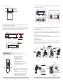
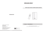
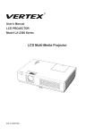
B3
170
161
L
W
A
GRANDVIEW REPRODUCING GENUINE COLORS
B2
H
B1
LF-MIRC84
LF-MIRC100
B1
B2
B3
84
1707x1280
2321
2196
100
55
665
2431x260x226
26.8/30.0
100
2032x1524
2646
2195
100
55
420
2756x260x226
29.4/33.4
LF-MIRC120
120
2438x1829
3052
2480
100
55
400
3162x260x226
33.0/37.4
LF-MIRC150
150
3048x2286
3667
2937
100
55
400
3777x260x226
42.2/47.4
LF-MIRC77
77
1705x 959
2319
2195
100
55
985
2429x260x226
26.4/29.8
LF-MIRC80
80
1771x 996
2385
2197
100
55
950
2495x260x226
27.0/30.4
92
2037x1146
2651
2197
100
55
800
2761x260x226
29.0/33.0
100
2214x1245
2828
2196
100
55
700
2938x260x226
30.5/34.5
31.6/35.8
LF-MIRC92
LF-MIRC100
2.35:1
Instruction Manual for
Cyber Series Recessed-Ceiling Screen
LF-MIRC106
106
2347x1320
2961
2196
100
55
625
3071x260x226
LF-MIRC120
120
2657x1494
3271
2195
100
55
450
3381x260x226
34.2/38.8
LF-MIRC150
150
3321x1868
3940
2519
100
55
400
4050x260x226
44.0/49.4
LF-MIRC100
100
2337x 995
2951
2196
100
50
955
3061x260x226
31.2/35.4
LF-MIRC110
110
2571x1094
3185
2195
100
50
855
3295x260x226
33.0/37.5
LF-MIRC120
120
2805x1193
3419
2194
100
50
755
3529x260x226
35.0/39.8
LF-MIRC130
130
3038x1293
3657
2194
100
50
655
3767x260x226
40.5/45.6
LF-MIRC140
140
3272x1392
3891
2193
100
50
555
4001x260x226
42.8/48.0
Note:
1. Due to product updates, sizes and specifications are subject to change at any time.
The tolerance for L is approximately ± 5mm (3/16 inches).
2. Actual dimension is measured by: total screen length L x end cap depth x end cap height.
Questions & Answers
Fabrics of Grandview motorized screen can be used for years, most problems are cost by simple incidents. If
problem occurs, please find the list below for some common solutions. If problems keep on, please contact
authorized agent of Grandview or call service number: (8620)34806166
Reason
Sc reen responds
Battery mis-installed or powerless
nothing to any
operation
Power line disconnection
Solution
Please check about the batteries as instruction manual.
Please connect the power line as instruction manual.
One year warranty
Grandview provides one year warranty for motorized screen. Contents of warranty include replacement of spare
parts while problems occur with correct operation. Not include inappropriately operating the screen or uninstall the
Model:CB-MIRC or LF-MIRC
screen by self. You should reserve in advance for the repair with Grandview or appointed service center.
Thank you for purchasing a Grandview projection screen.
Before use, please read instructions carefully. After installation, store instructions for future reference.
Http://www.grandviewscreen.com
(1) For adjusting the viewing area, please insert the adjustment to regulate adjustment hole. A
Caution
clockwise adjustment will increase the viewing area for about 13mm.
Note: After pressing the up button, you will need a few seconds to see the adjustment of screen;
Please do not operate the following step before step1 to avoid damages of screen.
(2) A counterclockwise cycle can adjust the distance to 13mm between casing and rod.
Please be careful while operating, too much retracting will cause the damages of screen and motor.
Product Specifications
170
B3
B1
161
L
A
W
B1
B2
1. Please read carefully with this instructions before installation to avoid damage to product causing
by inappropriate installation or operation.
2. Please keep the screen away from hot sources, such as radiator, heating machine, fireplace,
loudspeaker or other relative device.
3. Only Plug with ground wire is acceptable.
4. Only accessories from authorized supplier is acceptable.
5. Please unplug the power wire when lighting and raining or not use with a long time.
6. Please handle the repair work to the professional agent.
7. Please prevent screen from wet and water .
8. As soon as the plug of the screen is connected to the power source, the screen is connecting
with electricity.
9. Please use the approved power line (three-core power line)/ device interface/power plug.
10. Please use the rating (voltage, amps) power line (three-core power line) / device interface/power
plug. If have any questions about power line/ device interface/power plug, please contact the
professional people.
11. After installation, please locate a power device in order to disconnect power or connect the power
plug to electrical socket. This electrical socket should be installed to a convenient position. If the
accident occurs during operation, please disconnect power or take out the power plug.
12. The ceiling or wall used for fixture installation must be secure enough; load-bearing requirement
must be 4 times of the screen to prevent the screens from falling.
and after pressing the down button, you will see the position changed of screen.
H
Warnings: Please prevent screen from wet place to avoid electric or fire dangerous.
Warnings
Please notice the non-insulated voltage of the
spare parts to prevent from electric dangerous.
To prevent from electric
dangerous, please don't
remove the end cap. There
is no need for users to
check the parts inside,
please handle the problems
to professional repairman.
B1
B2
CB-MIRC72
72
1463x1097
1847
2158
30
50
850
1913x260x226
20.0/23.0
CB-MIRC84
84
1707x1280
2131
2161
50
50
670
2197x260x226
24.0/27.2
CB-MIRC100
100
2032x1524
2456
2155
50
50
420
2522x260x226
26.6/30.2
CB-MIRC120
120
2438x1829
2862
2160
50
50
120
2928x260x226
29.3/33.4
CB-MIRC150
150
3048x2286
3472
2607
50
80
80
3538x260x226
35.4/40.2
CB-MIRC180
180
3658x2743
4147
3064
80
80
80
4213x260x226
46.2/51.8
CB-MIRC200
200
4064x3048
4553
3369
80
80
80
4619x260x226
50.5/56.8
CB-MIRC240
240
4877x3658
5366
3979
80
80
80
5432x260x226
59.6/66.8
24.5/27.8
CB-MIRC77
77
1705x 959
2129
2160
50
50
990
2195x260x226
CB-MIRC80
80
1771x 996
2151
2157
28
50
950
2217x260x226
24.7/28.0
CB-MIRC92
92
2037x1146
2461
2157
50
50
800
2527x260x226
27.0/30.5
CB-MIRC100
100
2214x1245
2638
2156
50
50
700
2704x260x226
28.2/32.0
CB-MIRC106
106
2347x1320
2771
2161
50
50
630
2837x260x226
29.2/33.0
Please operate according to the user manual
CB-MIRC120
120
2657x1494
3081
2155
50
50
450
3147x260x226
31.6/36.0
with the screen.
CB-MIRC150
150
3321x1868
3750
2409
50
80
300
3816x260x226
41.2/46.5
CB-MIRC180
180
3985x2241
4474
2782
80
80
300
4540x260x226
48.5/54.5
CB-MIRC200
200
4428x2491
4917
3032
80
80
300
4983x260x226
52.8/59.5
Note:
1. Due to product updates, sizes and specifications are subject to change at any time.
The tolerance for L is approximately ± 5mm (3/16 inches).
2. Actual dimension is measured by: total screen length L x end cap depth x end cap height.
1
B3
14
D. External Wall Switch (optional)
Description
The wall switch is available for a fixed location. Please
connect RJ11 plug to EXTCTRL input on the screen.
Wall Switch
(optional)
Note: please use a cord for a far location.
Aluminum Casing
Hook
Side View
E. Synchro Power Relay(optional)
M12 Nut
After connecting the Wireless Synchro
Converter, the screen can be controlled
IR to RF receiver
Power line
by FM modulation wireless controller
which can cooperate with Sychro Power
M12 Bar
Screen Fabric
Relay and switch of projector to control
the up and down of screen synchronously.
Power Synchro
and IR
Sychro Power Relay and
Wireless Synchro Converter
Low Bar
Front View
三. Screen Adjustment
(Please take apart the baffle when adjusting the screen. And please reinstall the baffle after adjusting.)
Bracket
Accessaries
Motor Positioning
Avoid the overheating of motor; please do not use the screen
M12 Bar (4p cs)
M12 Nut (12pcs)
Hook (4pcs)
Pressing Piece (2pcs)
M10X100 Expansion
Screw (8pcs)
over 4 seconds for extending and retracting continuously. The
motor needs 4 minutes to cold down and the motor do not need
any lubricant. The standard factory setting of upper and lower
limitation is perfect. To avoid the damage, please contact the
Motor adjusting slot
professional people or local dealers for repairing.
Pleae adjust the motor adjusting slot using M4 allen key
Wrench (1pc)
“Screen Extending” Adjustment
Hanging Board (2pcs)
M6 Allen Screw (4pcs)
M6 Nut (4pcs)
M5 Screw (4pcs)
Operate the adjustment when the screen extends completely:
(1) For adjusting the viewing area, please insert the adjustment to regulate adjustment hole. A clockwise
adjustment will increase the viewing area for about 13mm.
“ button, you will need a few seconds to see the adjustment of screen; and after
Note: After pressing the“ Up
pressing the“down“ button, you will see the position changed of screen.
Infra red Remote Contro ller (1pc)
External Infrared Receiver (1pc)
(2) With the over-adjustment, a counter-clockwise adjustment will return the screen. This adjustment can be
operated when the screen stops at the lowest postion without controlling.
Please be careful while operating, too much retracting will cause the damages of screen and motor.
“Screen Retracting”Adjustment
Reference:
(Note: This adjustment is not safety, please contact the professional people for repairing and avoid damaging of
screen and warranty failure)
“Caution”we strongly recommend that do not regulate the screen limitation privately. The standard limitation of
screen is set from the factory and this standard can satisfy the requirement of users.
13
2
Trigger Line (1pc)
Instruction Manual (1pc)
Installation Instruction
Push down
Batteries Installation Instruction:
When the signal of the Controller is faint, please replace the batteries
This screen needs to be recessed into the ceiling, and this instruction manual shows us the grille-ceiling and
wood-ceiling as example. Please install the screen according to different applications. This screen needs to be
recessed at the best viewing angle in order to improve the image. Take out all the parts from the packaging and
follow the accessories guideline to ensure you have all parts.
Concrete Roof
as follow steps:
1.Reverse Controller to the back, push down as the arrow mark to open
the cover.
2.Installtwo cells of battery and set the direction of positive and
100
This number of bars can
be four and two according
to different installation.
Hook
M12 Bar
negative electrode just like the chart shows.
3.Close the battery cover.
Hanging Board
Screen
Ceiling
L minus 26mm
(The width of groove)
158(The width of groove)
170(The length of screen)
L(The length of screen)
二. External Control System
Screen Fabric
Four control systems are available
for motorized screen
EXT CTRL
(1)Manual Control
Low Bar
TRIG
(2)Infrared Remote Control (IR)
一. Grille-Ceiling Mount
EXT IR
Dry Contact/RS232
Trigger
External Infrared Receiver
(3)Dry Contact
(4)Switch
1.Choose a position according to the required space, and then take apart the ceiling (figure 1). Please measure the
distance H between concrete roof and ceiling surface correctly (figure 2).
A.Manual Control:
The manual control button is under
power box:
Stop
Up
(Close to power line)Cyclic Control
Concrete Roof
Down
Stop
Roof Surface
Cyclic Control
H
Take apart the ceiling
Grille-ceiling
Ceiling Surface
B. Infrared Remote Control:
Because of the recessed mount, the
Fi gur e 1
Fi gur e 2
external infrared EXT lr input must be in
serted by external infrared receiver, then
2.This screen equips bracket, and build up the hanging bracket using the hook, M12 nut and M12 bar. Cut the length
please fix it in eyes for control.
of M12 bar to H minus 100mm(H is the distance between concrete roof and ceiling surface) (Note: H is 500mm, the
length of hanging bracket is 400m which is 500mm minus 100mm) (figure 3).
Brooch
External Infrared Input
Hook
Approximately
150mm
H minus 100mm
C. Trigger :
100. 0
M12 Nut
1. Please connect 2,5mm plug of trigger to
the TRIG input on the screen; connect 3.5mm
Projector
plug to the output on trigger (only for the equip
ments which have trigger function)
M12 Bar
2. The projection screen will automatically
Mz2 Screw (4pcs)
lower when the projector is on. It will automatically
Trigger Line
TRIGGER
retract when the projector is turned off
figur e 3
3
12
3.Please measure the security distance between hanging brackets (figure 4), and fix the hanging brackets on the
11. Installation Completed (figure 27).
ceiling using expansion screws (figure 5).
H
H minus 100
Fo ur Hangi ng
Boar ds ar e in middl e.
180
100
L minus 94
100
Figure27
Note: the upward instructions are only suitable for the distance H which between 200-600mm; if the distance is
figur e 5
figur e 4
greater than 600mm, please follow the steps as below:
1)Install the hanging bracket at a required position before ceiling fitment (M12 bar is not provided) (figure 28).
2)Saw an oblong groove at a completed ceiling (note: please ensure the hanging bracket must be installed in the
middle of this groove) (figure 29). The rest of steps can follow the instructions as before!
4, Please follow the below steps to install the power cord which recessing in casing, and plug in the external infrared receiver
(because of the recessed mount, the external infrared receiver must be ready for control).
1)Take out the power cord (figure 6).
2)Loose the screws of power box and take out the power box (note: the power box must be buttoned on the hanger of bracket
H minus 100
according to figure 11, please put up and move back the power box to take out), because the power cord has a limit, please do
not draw it strongly.
3)Loose and take out two rubber screws, then remove the end cap (figure 8-9).
100
4)Remove the line cover of end cap, then fill in the power line. Afterward, stuck the line cover back to end cap, then install the
L minus 94
Not completed ceiling
power line outside the casing.
5)Install the end cap again (figure 10)
Figure28
L(Total length of screen )minus 26mm
6)Insert the external infrared receiver to EXT IR hole (figure 10) (note: please put the completed external infrared receiver into
inside frame of screen to avoid the pressing from screen). Then install the power box back to bracket (note: ensure the power
box is buttoned on the hanger of bracket) (figure 11).
Scr ew
79
100
158
Two Hanging
Boards are in middle.
Rubbe r Scr ew
End Cap Boar d
Li ne Cover
Pow er Box
Figure29
Pow er Li ne
Pow er Li ne
Product Instruction
LED
UP
STOP
DOWN
Micro-up
Micro-down
Model:AC127
Button Function and Operation Instruction :
1.Press UP button to lift the screen
2.Press STOP button to stop the screen
3.Press DOWN button to lower the screen
4.Press MICRO-UP button to retract the screen in small
increments(150ms for each movement)
5.Press MICRO-DOWN button to lower the screen in small
increments (150ms for each movement)
Cautions:
1.The minimum distance between Controller and Receiver: 50cm
2.Workable within 8m in horizontal directionfrom the Receiver to the
Controller
3.Do not cover the Controller’s launching port while operation
4.Strictly banoperation in wet or high temperature environment.
5.Replacing batteries when the signal is faint or no signal.
6.Batteries for the Controller: 2 units CR2032 button cells.
11
Fi gur e6
Fi gur e7
Fi gur e8
Fi gur e9
M4 Screw
TRIG(Trigger)
Switch
Power Box
Signal Output
EXT IR(External
Infrared Receiver)
Bracket
Note: the power box must be
buttoned on the hanger of bracket.
EXT CTRL(Dry
Contact/RS232)
End Cap Board
Fi gur e 11
Fi gur e 10
4
5.Please stay the screen in the opposite direction, and fix the left and right hanging board on the screen using
M6 screw and nut (figure 12).
Casing Groove
M6 Allen Screw
Note: the upward instruction shows us installation of external control system, if the users want to add other control
systems, please follow the steps as below:
M6 Nut
Hanging Board
1)Loose the screws of power box and take out the power box (because
5.0
the power cord has a limit, please do not
draw it strongly). Then loose two rubber screws again, and remove the
end cap (please ensure the power line is
fixed), step 3 can be follow.
1) Stay the M6 allen screw
in the groove of casing.
2) Install the hanging 3) Please ensure the
distance between edge
board
of hanging board and the
edge of casing is 5mm.
figure 12
4) Fasten the hanging board
using M6 nut, and install other
hanging board at the same way.
2)Insert the control system signal line to corresponding output (figure 11),
Power Line
and take out the signal line from control
Signal Line Exit
system signal line exit (figure 19).
3)Reinstall the end cap after completed control system and fasten the
two rubber screws then reinstall the power box and fasten two screws
6. Install the whole screen on the hanging bracket (figure 13-14)
Figure21
according to step 8.
10. Install the large and small baffle
1)Please ensure the security lock is unlocked (figure 20 and 22).
"
2)Install the large and small baffle (figure 21)
3)Unlock the security lock of baffle (figure 23), insert the plug of
security to
" a hole of end cap (figure 24), if the baffle can not move
up that please align baffle with ceiling board.
Figure13
Figure14
7. Fix the screen using M12 nut (figure 15), then adjust the security distance to H (the distance between concrete roof and ceiling
surface) using adjusting screw. Loose the M12 nut and fix the whole screen, and then connect the power (figure 16).
Note:
Recessed motorized screens under 120” utilize both a large and small
trim cover. Recessed motorized screens above and including 120”
utilize only one large trim cover.
Figure22
All Tab-tensioned Recessed motorized screens utilize only one large
trim cover.
M12 Nut
M12 Screw (4pcs)
Top Groove
Low Groove
Figure15
Figure16
1) Insert the baffle to top groove.
8. Cut the separated ceiling board in a suitable size, which can fill in the size of space as screen (figure 17-18).
Two surface at
the same level
3) Press the baffle slightly
2) Stay flat the baffle,
4) The installation of
and clip it to low groove. and align it with ceiling board. large baffle is the same.
Locked
Figure24
Figure25
Figure18
5
Two surface at
the same level
Figure23
Unlocked
Figure17
Small Baffle
Large Baffle
10
Figure26
6. Fix the screen using M12 nut, then fasten the nut by wrench (accessories) (figure 13-14); until the ornament
Note: the upward instruction shows us installation of external control system, if the users want to
board align the ceiling (figure 15) and connect the power.
add other control systems, please follow the steps as below:
1)Loose the screws of power box and take out the power
box (because the power cord has a limit,
please do not draw it strongly). Then loose two rubber
M12 Screw
screws again, and remove the end cap
(please ensure the power line is fixed), step 3 can be follow.
Not provided
(screwdriver
can replace)
Wrench
2)Insert the control system signal line to corresponding
output (figure 11), and take out the signal
Signal Line Exit
line from control system signal line exit (figure 18).
Wrench
Figure13
Power line
3)Reinstall the end cap after completed control system
Figure14
and fasten the two rubber screws then
reinstall the power box and fasten two screws according
Align the ornament
board with ceiling
Figure19
to step 4.
Figure15
7.Please ensure the hexagon surface of nut and inside surface of casing are at the same level (figure 16); stay the
10. Install the large and small baffle
1)Please ensure the security lock is unlocked (figure 20 and 22).
2)Install the large and small baffle (figure 21)
3)Unlock the security lock of baffle (figure 23), insert the plug of security to a
hole of end cap (figure 24), if the baffle can not move up that please align
baffle with ceiling board.
pressing piece on the nut (figure 17-18)
Note:
Recessed motorized screens under 120” utilize both a large and
small trim cover. Recessed motorized screens above and
including 120” utilize only one large trim cover.
Two surfaces are
at the same level
Figure20
Pressing Piece
All Tab-tensioned Recessed motorized screens utilize only one
largetrim cover.
M5 Screw
Figure16
Figure17
Top Groove
Figure18
Low Groove
8. Insert the external infrared receiver to EXT IR hole(figure 18), because of the recessed mount, the external
infrared receiver must be ready for control, then install the power box back to bracket .
1) Insert the baffle
to top groove.
(note: ensure the power box is buttoned on the hanger of bracket) (figure 19).
Two surface at Small Baffle
the same level
Large Baffle
Two surface at
the same level
3) Press the baffle slightly
2) Stay flat the baffle,
4) The installation of
and clip it to low groove. and align it with ceiling board. large baffle is the same.
Figure21
Bracket
TRIG(Trigger)
Locked
Unlocked
Power Box
Note: the power box must be
buttoned on the hanger of bracket.
EXT CTRL ( Dry
Contact/RS232 )
Button
EXT IR(External
Infrared Receiver)
Screw
Figure 18
Figure 19
Figure22
9
Figure23
6
Figure24
11. Installation Completed (figure 25).
3.Please measure the security distance between hanging brackets (figure 4), and fix the hanging brackets on the
ceiling using expansion screws (figure 5).
L minus 94
Fo ur Hangi ng
Boar ds ar e in middl e.
L(Tot al lengt h of scr een )minus 26m m
79
100
158
100
H
H minus 100
Fi gur e 5
Fi gur e 4
Figure25
.Note: the length of M12 bar is 500mm. Please prepare the bar your self if the distance H (between concrete roof
4, Please follow the below steps to install the power cord which recessing in casing .
and ceiling) is longer than 600mm.
1)Take out the power cord (figure 6).
2)Loose the screws of power box and take out the power box (note: the power box must be buttoned on the hanger
二. Wood Ceiling
of bracket according to figure 11, please put up and move back the power box to take out), because the power
cord has a limit, please do not draw it strongly.
3)Loose and take out two rubber screws, then remove the end cap (figure 8).
1. Saw an oblong groove at a required position (figure 1); Please measure the distance H between concrete roof
4)Remove the line cover of end cap, and then fill in the power line. Afterward, stuck the line cover back to end cap,
and ceiling surface correctly (figure 2).
then install the power line outside the casing (figure 9)
5) Please complete the installation of end cap and fasten two rubber screws; do not need to install the power box
at this moment.
L( Total length of screen ) minus 26mm m
8m
15
Screw
Power Box
Concrete Roof
Figure1
Li ne Cover
Roof Surface
H
Wood Ceiling
EXT IR(External
Infrared Receiver)
Rubber Screw
End Cap
Power Line
Pow er Li ne
Ceiling Surface
Figure2
2.This screen equips bracket, and build up the hanging bracket using the hook, M12 nut and M12 bar. Cut the length of M12 bar to
Figure6
Figure7
Figure8
图10
Figure9
5. Install the whole screen on the hanging bracket (figure 11-12)
H minus 100mm(H is the distance between concrete roof and ceiling surface) (Note: H is 500mm, the length of hanging bracket is
400m which is 500mm minus 100mm) (figure 3).
H minus 100mm
Brooch
Hook
100. 0
M12 nut
M12 Bar
Figure11
Figure12
Fi gur e 3
7
8