1
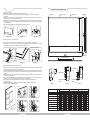
GRANDVIEW REPRODUCING GENUINE COLORS
User's Manual for
Large Flat Series Edge Fixed Frame Screen
GRANDVIEW REPRODUCING GENUINE COLORS
Grandview Crystal Screen Canada Ltd.
Model:LF-PExxx
#11- 3751 North Fraser Way,
Marine Way Business Centre,
Burnaby, BC, Canada V5J 5G4
Tel: 1-604-412-9777 Fax: 1-604-412-9796
Website: www.grandviewscreen.ca
Thank you for purchasing a Grandview projection screen.
Guangzhou Grandview Crystal Screen Co., Ltd.
P.O. 511400 Federal Ind. Zone No. 363, Yushan West Road,
Shiqiao, Panyu District, Guangzhou, Guangdong, China
Tel: +8620-8489-9499 Fax: +8620-8480-3343
Website: www.grandviewscreen.com
www.grandviewscreen.com.cn
Before use, please read instructions carefully. After installation, store instructions for future reference.
ISO9001:2000
International Certification
Note: Please make sure the concrete ceiling is strong enough to be bear the weight of 20kg or
above in order to avoid any property lost and casualty due to insufficient bearing.
Product Structure
Note
1. Please pay attention to the rear and front sides of screen fabric during installation. There is label attached to rear side of
screen fabric.
2. Kindly handle with care to avoid distortion due to crash of the aluminum frame material.
3. In case of infrequent use, please cover the screen fabric with cloth (or something else fit to cover) to prevent screen fabric
from dusty .
4. Do not clear screen fabric with detergent of corrosivity such as diluent.
5. Please clean the velvet wrapped on the frame along the velvet grains. Prevent velvet from crash to avoid damage.
6. Do not scrape screen fabric with fingers or edge tool, which would leave flaws or marks on fabric.
7. In order to avoid any unexpected injury, it is advisable to manage and install the fixed frame screen by adult.
Fixing parts
Upper bracket
Pre-measured tether
UP (down) frame
Corner piece
components
Warning: Regardless of the warnings would possibly lead to damage to product or casualty due to any improper operation.
Decoration cover
Mandatory: The screen should be installed where is strong enough to bear its weight, or it would cause accident by falling off.
Tension rod
Supporting bar
Tension rod
Note: Please don’t disassemble screen for replacement of parts. Please kindly contact to after sale department for service if
any fault. It is not prior to notice if there is any change on product. Please refer to the product.
Snap lug
Screen fabric
Parts List
Up and down frames( 4 pcs in equal length)
Left and right frames( 2 pcs in equal length)
Decoration cover for up and down frames
( 4 pcs in equal length)
Decoration cover for left and right frames
( 2 pcs in equal length)
Φ5mm tension rods for up and down frames
(4 pcs in equal length)
Φ5mm tension rods for left and right frames
(2 pcs in equal length)
Lower bracket
Supporting bar (1 pcs)
Left (right) frame
Mounting brackets with pre-measured tether (1 set)
Decoration cover
Screen fabric (1 pcs)
Outer side
Φ3*18 Tapping screw
Erecting rack for
supporting bar
M5*15 screw
M5*8 screw
Inner fixing part
Outer fixing part
Slot for snap lug
Rear
Base of
corner piece
Corner piece
Decoration cover
Corner piece components
Corner piece parts (4 sets)
Cover for corner piece
(4 pcs)
Inner fixing parts for frame
(2 pcs)
Outer fixing parts for frame
(2 pcs)
Erecting rack for
supporting bar(4 pcs)
Snap lug
( provided according
to screen size)
M5*8mm screw ( 24 pcs)
Φ3*8mm tapping screw
( 4 pcs)
Front
Inner side
Sectional view of frame
M5*8 screw
Inner side
Fixing parts
Sketch for structure of Edge fixed frame screen
User's manual (1 copy)
Warranty card ( 1 set)
Qualification certificate ( 1 set)
1
6
Φ5*40 tapping screw ( 4 pcs)
and expansion tube(4 pcs)
Overall view and dimension
Diagram 19
Diagram 20
Details A
Upper frame-1
Details B
Upper frame-2
Distance of up and down brackets(Hgb)
7. Assembly of screen fabric
a. Make sure the screen fabric is assemble in the place where is clean and tidy.
b. Please put the rolled screen fabric onto frames with front side of fabric facing up, then roll the fabric to spread slowly.
( diagram 19)
c. Please put the tension rods through 4 edges of fabric. Please be noted that the 2 pcs of left and right tension rods are in the
equal length, so are the 4 pcs of up and down tension rods.
d. Adjust distance from snap lugs according to the snap lugs’s holes at the edges of fabric, then hold the fabric with hands to put
the snap lugs go through the holes. ( diagram 21) (It is advised to handle the snap lugs on up and down frames. Snapping
from middle to edges.)
e. Please make necessary adjustment on fabric to keep it smooth and flat from wrinkles.
Diagram 21
8. Installation of cover for corner piece and frame
a. Mount the cover for corner piece onto the slot of base and use ⍉ 3*8mm tapping screws to fix it. (diagram 22)
b. Mount the frame cover with rubber onto the frame and press it down in position until it is tight. (see diagram 23-24). The frame
cover with label should be placed onto lower right corner at the front side of screen.
Press down to make it tight
Corner
piece cover
Clip
Frame decoration cover
Rubber
Snap lug
Slot
Frame
Details C
Base of
corner piece
Φ3*8
tapping screw
Diagram 22
Length of bracket(Lgb)
Press down and make it tight
Diagram 23
Diagram 24
9. Assembly of bracket set and mount the screen onto wall
a. Please find out the position to put the screen and drill holes in wall according to the mounting holes of bracket. Please fix the
bracket onto wall with the expansion tubes and screws provided.
b. Please let the lower bracket drop naturally and it would be in position with help of the pre-measured tether. Please mark the
position of mounting holes for lower bracket, drill the holes and fix the lower bracket with expansion tubes and screws
provided.
c. Measure distance from upper and lower brackets which should be H+2mm. Please make necessary adjustment if the
distance doesn’t meet the above.
d. Turn the buckle on lower bracket counter clockwise until it reaches the end to make the lock mark on the buckle stops at
direction of 12 or 3 o’clock ( upright or right position) to make it unlock ( see diagram 26)
e. Please mount the screen onto brackets. Make sure hooks of brackets go in the slots of up and down frames.
( see diagram 27-28)
f. Please finish the installation by turning the buckle clockwise until it reaches the end to lock the lower frame.
( see diagram 26 on the right and diagram 29)
Upper
frame
Wall
Upper
bracket
Unlock
Premeasured
tether
Diagram 27
In unlock
condition
In lock
condition
Lower
frame
Lower
frame
lower bracket
Diagram 25
Upper bracket
Pre-measured
tether
Details A
Lower bracket
Buckle
Details B
Specification (Inch)
Width of viewing size
Height of viewing size
Lock
Lock mark
Diagram 26
Pre-measured
tether
Overall width of the screen
Overall height of the screen
Nos. of snap lug for the up and down frame
Nos. of snap lug for the left and right frame
Distance of up and down brackets
Length of bracket
Length of packing size
图2 9
Diagram 28
5
Diagram 29
2
Details C
Installation instructions
Installation instructions
Open the package and take out all of the parts. Kindly check the types and quantity of the parts according to user’s manual.
Please put all of frames on clean and flat dest or ground in a square. ( see diagram 1) Please pay attention to correct placement
of aluminum frames. ( the front side should be facing up, while the inner side should be facing the center of the screen). Please
follow the order shown in diagram to assemble the frames.
3. Assembly of corner piece
a.Please insert corner piece into the slot of horizontal frame till it reaches the end. There should not be any apparent seam
found. Please use M5*8 screw to fix it, see diagram 8-10.
b.Assemble other corner piece in the same way.
Base of
corner piece
Snap lug
Upper frame
(4 pcs in equal length)
Upper frame
(4 pcs in equal length)
Left frame ( 2 pcs in equal length)
Insert into the slot
Left frame ( 2 pcs in equal length)
Down frame
( 4 pcs in equal length)
M5*8 screw
upper or
lower frame
Corner piece
Diagram 9
Diagram 8
Diagram 10
4. Join the frames together
a.Please insert the other side of corner piece into the vertical frame till it reaches the end. There should not be any
apparent seam found. Kindly use M5*8 screw to fix it, see diagram 11-12.
b.Join the other vertical frame with up and down frame in the same way, see diagram 13.
Down frame
( 4 pcs in equal length)
M5*8 screw
Diagram 1
Corner
piece
1. Please put the snap lugs into lug's slot of frame ( see diagram 2) according to the Nos. of holes in the screen fabric.
vertical
frame
Horizontal frame
Insert into the slot
Inner fixing part for frame
Screw hole
Insert into the hole
Screw hole
The hole should face
the center of the screen
Snap lug
Diagram 2
Diagram 3
Diagram 12
Square hole
Insert into the frame
Diagram 5
Erecting rack for
supporting bar
Supporting bar
Diagram 4
2.Joint of up and down frames
a.Put the inner fixing part for frame through hole on the base of supporting bar ( see diagram 3). Please pay attention to the
difference of inner and outer fixing part of frame. The inner fixing part is with 5 holes, 4 out of which has screw thread. The
middle hole of inner fixing part should face the center of screen. It would cause failure in assembly if mistaking the inner and
outer fixing part or the incorrect placement of it. Please refer to diagram 4 for correct assembly.
b.Please insert the base of supporting bar with inner fixing part mentioned above into the frame ( diagram 5) to join the 2 pcs of
upper frames together. Please be noted that the base of supporting bar should be inserted till it reaches the end to avoid any
apparent seam between frames and the base of supporting bar.
c.Assembly of outer fixing part for frame. There are 4 holes in it and 2 gaps on the edge. The gaps should face the center of
screen ( diagram 6). Please put the outer fixing part onto the slot for snap lugs and adjust its position to match the holes of
inner fixing part with screw thread. Please fix the inner and outer fixing parts wit M5*8 screws ( diagram 7).
d.Assemble lower frame in the same way.
M5*8 screw
Erecting rack
for supporting
bar
Supporting
bar
Hook
Use flat screw
driver to unlock
the hook
Hook
Attach the
supporting
bar with the
erecting rack
along the extending part
Diagram 14
Diagram 15
Diagram 7
Diagram 17
3
Diagram 16
6. Join the other set of horizontal frame
Join the other set of horizontal frame with the vertical frames with screw in the same way as the step 4 and step 5
mentioned above, see diagram 17-18. Please check it again to see if all of the screws are tighten.
Outer fixing
part for
frame
Note: The
gaps should
face the
center of
screen
Diagram 6
Diagram 13
Note: It is not advise to disassemble or assemble the supporting bar frequently. If it is necessary, please use the flat
screw driver to insert into square hole in supporting bar to unlock the hook for disassembly, see diagram 16.
Erecting rack
for supporting bar
Lug’s slot
Diagram 11
5. Assembly of supporting bar
Attach the supporting bar with the erecting rack along the extending part on it till it reaches the end and the hook would
clip into the square hole in the supporting bar, see diagram 14-15.
Diagram 18
4