1
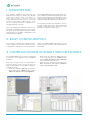
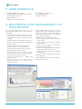
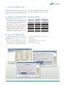
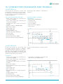
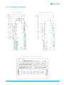
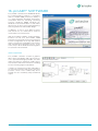
smART P500.
PROTECTION RELAYS.
This document may be subject to changes.
Contact ARTECHE to confirm the characteristics and
availability of the products described here.
Moving together
CONTENTS
1.
2.
3.
4.
5.
6.
7.
8.
9.
10.
11.
12.
13.
14.
15.
16.
17.
18.
19.
20.
21.
Description |
4
Easy configuration |
4
Communications in Smart Grid networks |
smART P500 relay features |
User interface |
4
5
6
Recording and measurement of parameters |
Load profile |
7
Oscillographic registers |
Fault report |
7
7
Event record |
8
Self-diagnostic |
8
Automation capacity |
8
Connection diagrams and models |
Connections |
Dimensions |
9
11
12
proART® software |
Setting ranges |
13
14
Technical specifications |
Model selection |
20
22
Quality and environment |
Service |
6
23
23
smART P500 | Protection relays
3
1. DESCRIPTION
The smART P500 series devices are
Multifunction Protection Relays with Digital
Technology, which make it possible to
carry out protection, control, metering
and communication functions in electrical
systems, particularly in Distribution. They
can be used as stand-alone equipment or
integrated within a system.
There are multiple possibilities for their configuration and data browsing, event recorders, faults, and oscillographic analysis that are
supported by the proART® configuration and
communication software.
The smART P500 Protection Relay family consists of different models that allows for the protection, measurement, and management of a
large number of applications, both for electrical
networks and power distribution substations.
The following models are available: recloser
control, feeder protection, and transformer
backup, capacitator bank protections and
backup for sub-transmission lines.
2. EASY CONFIGURATION
The proART® software, developed using the
Visual Studio.net platform, allows for the
configuration and survey of any equipment
within the smART P500 relay family in a very
simple and fast manner, which facilitates its
field setup.
3. COMMUNICATIONS IN SMART GRID NETWORKS
The smART P500 series of relays is designed
to facilitate its integration into SmartGrid
networks.
They have a large variety of communication
protocols which can be chosen by the user
with the keyboard or the proART® software in
its different ports:
›
4
›
›
Rear ports (2): ArtCom®, DNP 3.0 Level
2 slave proprietary port, MODBUS RTU,
Harris 5000, IEC 60870-5-101, PROCOME
and Smart P2P (Peer to Peer).
Ethernet Port: ArtCom® Proprietary port,
DNP 3.0 TCP/IP and UDP/IP, MODBUS
TCP/IP, IEC 60870-6-5-104.
Front Port: ArtCom®, DNP 3.0 Level 2 slave
proprietary port, MODBUS RTU, Harris
5000, IEC 60870-5-101, and PROCOME.
smART P500 | Protection relays
4. smART P500 RELAY FEATURES
PROTECTION & AUTOMATIC FUNCTIONS
›
›
›
›
›
›
›
Phase timed overcurrent (51).
›
Instantaneous sensitive neutral overcurrent
(51GS).
›
›
›
›
›
›
Phase timed neutral overcurrent (51G).
Residual timed overcurrent (51N).
Phase instantaneous overcurrent (50).
Neutral instantaneous overcurrent (50G).
Residual instantaneous overcurrent (50N).
Instantaneous sensitive neutral overcurrent
(50GS).
Directional of the phase overcurrent
functions (3X67).
Directional of the neutral overcurrent
functions (3x67N)
Directional of the sensitive neutral
overcurrent functions (3x67GS).
Open phase (46OP).
Negative sequence overcurrent for
a defined time and inverse time (46
DT/46IDMT).
Circuit breaker faiture (50BF).
›
›
›
›
›
›
›
›
›
›
›
›
›
›
›
›
Current Imbalance between star-connected
banks (61).
Voltage unbalance protection (3x47).
Undervoltage, 4 levels (27).
Overvoltage, 4 levels (59).
Neutral overvoltage (59N).
Overvoltage due to unbalance
capacitator banks (59NC).
Underfrequency (81m), overfrequency
(81M), and frequency rate of change (81D).
Synchronism check (25).
Directional power protection (32).
Automatic reclosing with tripolar or
monopolar action (79).
High current lockout phase or neutral.
Fuse Loss (60FL).
Cold load pickup.
Fault location.
Sectionalizer mode.
Network Reconfiguration Automatism.
STANDARD FEATURES
OPTIONAL FEATURES
›
›
›
›
6 Setting groups.
›
›
›
Circuit breaker supervision (74TC/CC).
External battery supervision.
›
Self-diagnosis and internal temperature
supervision.
›
4 Digital outputs and 3 digital inputs.
›
1 front RS-232 port, 1 rear RS-232 port and
1 RS-485 port.
in
SMS Communication and control via SMS
messages with an external GSM Modem.
Ethernet Port (RJ45) that includes 4 digital
outputs/9 digital inputs.
8 Digital inputs and 7 digital outputs
module.
Bluetooth Port and USB (replaces the front
RS-232).
› smART P500 in
cubicles.
smART P500 | Protection relays
5
5. USER INTERFACE
All smART P500 relays include:
›
›
›
›
4X20 LCD display with adjustable contrast.
3 Communication ports.
›
›
›
Programmable function keys.
12 Configurable LEDs.
proART® software.
Optional Ethernet.
IRIG-B hourly synchronization.
6. RECORDING AND MEASUREMENT OF
PARAMETERS
The smART P500 relays allow for the
recording and measurement of the following
parameters:
›
›
›
›
›
›
›
›
›
›
›
6
Instantaneous values of currents of the
three phases, neutral and sensitive neutral.
Instantaneous values for phase and line
voltages.
›
›
Power quality (PQ) events: sags, swells,
voltage and current unbalances, losses of
phase and supply voltage; variations in
frequency and parameters of the CBEMA
curve (advanced model).
Reliability indices (advanced model):
Auxiliary voltage and voltage of the battery.
• System average interruption frequency
index (SAIFI).
Active, reactive, apparent power, by phases
and three-phase.
• System average interruption duration
index (SAIDI).
Active energy received and delivered.
• M o me n ta r y ave ra g e
frequency index (MAIFI).
Reactive power in the four quadrants.
• Customer average interruption frequency
index (CAIFI) affected only once.
Power factor by phases and three-phase.
Phase frequency and sequence.
Demands of currents, voltages, power
factor and active, reactive and apparent
power by phase and three-phase.
Sequence components in voltage and
current signals.
Harmonic components, THD, phasors,
distortion factor of the currents and
voltages by phase.
i n te r r u p ti o n
• Customer average interruption duration
index (CAIDI).
›
›
›
• Average service availability index (ASAI).
Unit temperature.
Statistical data relative to circuit breaker.
Measurement record.
smART P500 | Protection relays
7. LOAD PROFILE
With the smART P500 relay, up to 25
parameters (which can be selected by the
user) can be stored in non-volatile memory,
within the groups of instantaneous values
or energy accumulators, in time intervals
of between 1 and 60 minutes, with 1 minute
steps. A total of 3,000 records can be stored.
8. OSCILLOGRAPHIC REGISTERS
smART P500 protection relays allow:
›
›
›
Recording and storing without filtering
of the waveforms of instant voltage and
current values associated with the faults or
with triggers selected by the user.
Samples/cycle
Number of
cycles to store
16
3.000
10
16
20
200
32
2.000
7
32
20
180
64
1.000
7
64
20
140
128
500
7
128
20
100
Oscillographic registers: the number of
samples per cycle can be programmed: (16,
32, 64, 128), number of cycles to store (1 to
3.000; 1 to 2.000; 1 to 1.000; 1 to 500) and
number of pre-fault cycles (1 to 20).
Various examples of possible combinations
are shown in the following table:
Maximum number
of registers
9. FAULT REPORT
The smART P500 protections make it possible
to record the last 32 faults with the following
information:
›
›
Start, trip, extinction and duration of the fault.
Values of the current and voltage signals
of each phase, neutral and sensitive
neutral, during the pre-fault, trip and their
smART P500 | Protection relays
›
›
›
›
value limits (maximum or minimum as
applicable).
Cause of the trip.
Protection units that were activated.
Active group.
Directionality of the fault.
7
10. EVENT RECORD
With the smART P500 protection relay up
to 3.500 events related to the protection
operation can be recorded and stored:
programming changes, digital input and
output statuses, pickup and/or trip of
protection functions, automations, statistics,
etc.
RMS values for voltage and current signals
associated with each event are stored in
each event. The user can limit the events that
are stored by deactivating those which are
considered less important.
11. SELF-DIAGNOSTIC
The relay has various self-diagnostic
routines that make it possible to detect
possible hardware failures. In addition, the
relay monitors the equipment’s internal
temperature with the possibility of an alarm.
It also has a type of test, which checks the
operation of the LEDs, outputs, inputs, display
and keyboard.
12. AUTOMATION CAPACITY
Th e s m A RT P 5 0 0 p ro te c t i o n re l ay
incorporates advanced automated functions
including 40 user-programmable logic
functions, communication capacities, and
integration in SCADA systems.
Within these capabilities, the following is
emphasized:
›
›
›
›
›
8
It has teleprotection functions through
the use of the smART P2P protocol that
allows for the exchange of information in
a fast, safe, and optimized manner, making
the compliance of directional comparison
(DCB, DCUB, PUTT and POTT) and direct
transfer trip (DTT) schemes possible.
Teleprotection compares the local and
remote status to allow or block trips in
addition to any other application of interest,
such as for example load control, etc.
›
›
›
›
Protection can be controlled via mobile
phone, using the short message service
(SMS) which provides the equipment
with a broad, safe, and controlled level of
accessibility.
Up to 40 uses programmable logic
functions, making this application field
broader.
Has LEDs, physical and virtual buttons, as
well as user programmable digital inputs
and outputs, offering a wide variety of
options to satisfy any desired application.
The protection has 8 push buttons and an
LCD screen that provides programming
and operating information.
Automatic schemes for the reconfiguration
of ring-distribution networks can be
created out through the use of algorithms
whose objective is to clear a fault in an
electrical system and reconfigure it in such
a way that the number of services affected
is reduced to the minimum. The algorithms
operate locally, are automatic and do not
need any operator involvement in order to
achieve their goal.
Self-diagnostic functions and test routines
to inform and ensure optimal functioning
of the equipment at all times, parameters
monitored are internal battery voltage,
auxiliary voltage as well as hardware status
(Flash memory, SDRAM, SRAM, FPGA,
A/D).
Test mode that allows verification of LED
status, digital inputs and outputs, front
keyboard and screen.
smART P500 | Protection relays
13. CONNECTION DIAGRAMS AND MODELS
smART P500-AL
State-of-the-art protection, control and
measurement terminal for the state-of-theart protection, control and metering terminal
for the primary protection and back-up of
medium-voltage lines.
Technology and reliability in distribution
networks.
AVAILABLE PROTECTION FUNCTIONS:
ADVANCED MODEL FUNCTIONS
(ADDITIONAL):
›
›
›
›
›
›
›
›
›
›
›
›
›
Phase and neutral low instantaneous
overcurrent (50/50N).
Phase and neutral high instantaneous
overcurrent (50/50N).
Timed phase and neutral overcurrent
(51/51N).
Negative sequence (46IDMT(46DT).
Open phase (46FA).
›
›
›
›
›
›
Directionality (67/67N/67NS).
Frequency (81).
Synchronism (25).
Fuse loss (60FL).
Directional Power (32F/R).
Fault Locator.
Undervoltage (27).
busbar
3
Overvoltage (59).
Voltage unbalance (47).
Neutral overvoltage (59N)(64)).
52
Reclosing (79).
Cold load pickup.
monitoring
59
79
close open
27
Circuit breaker failure (50BF).
Circuit breaker monitoring (74TC/CC).
3
50
51
50Q
51Q
50
FJ
68
FF
67N
67
50N
51N
COLD
LOAD
PICKUP measurement
HCL
LF
1
81
O/U
81R
25
smART P500-AL
line
smART P500-BC
End-to-end solution for protecting and
controlling capacitor banks. In addition
to typical protection functions for these
elements, the unit monitors the bank in
real time and includes connection and
disconnection automations for achieving the
optimum power factor in the network.
59N
64
Precision and flexibility for optimum power
quality.
FUNCTIONS:
›
›
›
›
›
›
›
›
›
›
›
›
Phase and neutral low instantaneous
overcurrent (50/50N).
›
Automatism of automatic connection and
disconnection of individual banks.
Phase and neutral high instantaneous
overcurrent (50/50N).
busbar
Timed phase and neutral overcurrent
(51/51N).
3
Open phase (46FA).
Current Imbalance between star-connected
banks (61).
59
52
monitoring
Undervoltage (27).
Overvoltage (59).
3
Overvoltage due to a voltage unbalance
(59NC).
50
51
open
50N
51N
50FI
27
50Q
51Q
measurement
59
NC
Voltage imbalance (47).
Cold load pickup.
Circuit breaker failure (50BF).
Circuit breaker monitoring (74TC/CC).
smART P500 | Protection relays
smART P500-BC
line
9
smART P500-RC
Recloser control device, which is the result of
the ARTECHE Group’s experience in the design
and manufacture of distribution network
equipment. In addition to the traditional
functions used to control this equipment, this
AVAILABLE PROTECTION FUNCTIONS:
›
›
›
›
›
›
›
Phase and neutral low instantaneous
overcurrent (50/50N).
Phase and neutral high instantaneous
overcurrent (50/50N).
Timed phase and neutral overcurrent
(51/51N).
Negative sequence (46IDMT(46DT).
Open phase (46FA).
Undervoltage (27).
Overvoltage (59).
ADVANCED MODEL FUNCTIONS
(ADDITIONAL):
›
›
›
›
›
›
›
›
›
›
10
Directionality (67/67N/67NS).
device offers advanced protection and highprecision measurement functions.
Sturdy and safe for network automation.
›
›
Voltage unbalance (47).
›
Recloser (79). Blocking of recloser due to
high current.
›
›
›
›
Overvoltage due to a voltage unbalance
(59NC).
Cold load pickup.
Circuit breaker failure (50BF).
Circuit breaker monitoring (74TC/CC).
Sectionalizer.
busbar
3
Directional power (32F/R).
59
Synchronism checking (25).
Overvoltage due to a voltage unbalance
(59NC).
3
46FA 50 50Q 50FI 32
51 51Q
Frequency (81).
HCL
Fuse loss (60FL).
Automatism of automatic network reconfiguration.
67
67N 50N
51N
47
COLD
LOAD
PICKUP
27
measurement
recloser
Fault locator.
1
Bluetooth communication.
Communication through GSM modem and
SMS messages.
68
FF
LF
monitoring
close open
81
O/U
81R
25
smART P500-RC
59N
64
line
smART P500 | Protection relays
14. CONNECTIONS
Y-Y Connection
Open delta connection
A
busbar
busbar
A
B
B
C
C
N
VC
VB
IA
IB
IC
52
N
VA
port
COM2
port
COM2
port
COM1
front port
RX
TX
IN
802
803
VS
(optional)
NS
line
804
805
IA
806
B1
B2
B3
B4
B5
B6
C1
C2
C3
C4
C5
C6
C7
C8
C9
C10
C11
C12
C13
C14
C15
C16
ED1
ED2
ED3
ED4
ED5
ED6
ED7
807
808
809
8010
8011
ED8
ED9
ED10
aux.
supply
DC / DC
VA
port
COM2
RS-485
IB
RS-232
RS-232
IC
52
VS
B16
C17
(optional)
NS
line
C26
C27
C28
C29
C30
C31
C32
A1 +
A3 - Vaux
ED11
RS-485
RS-232
front port
RS-232
802
803
C24
C25
F.O.
port
COM1
801
IN
C20
C21
C22
C23
RX
TX
IRIG-B
B7
B8
B9
B10
B11
B12
B13
B14
B15
C18
C19
VB
port
COM2
F.O.
IRIG-B
801
VC
804
805
806
B1
B2
B3
B4
B5
B6
C1
C2
C3
C4
C5
C6
C7
C8
C9
C10
C11
C12
C13
C14
C15
C16
ED1
ED2
ED3
ED4
ED5
ED6
ED7
807
808
809
8010
8011
ED8
ED9
ED10
aux.
supply
DC / DC
B7
B8
B9
B10
B11
B12
B13
B14
B15
B16
C17
C18
C19
C20
C21
C22
C23
C24
C25
C26
C27
C28
C29
C30
C31
C32
A1 +
A3 -Vaux
ED11
Rear View: connections diagram
smART P500 | Protection relays
11
15. DIMENSIONS
Vertical model
158
128,5
74
38
220
243,06
215
263
38
ø5,5
Panel drilling (mm)
External dimensions (mm)
Horizontal model
263
243,06
74
128,5
38
ø5,5
215
150
38
158
220
Panel drilling (mm)
External dimensions (mm)
12
smART P500 | Protection relays
16. proART® SOFTWARE
The proART® software from ARTECHE allows
for communication between a computer
and the smART P500 protections family. It
is a multi-language Windows application
compatible with the following operating
systems: Windows 2000, Windows XP,
Windows Vista and Windows 7 and makes
efficient use of object oriented programming,
achieving harmonic and scalable design.
In addition, it has an open data structure
that allows for its maintenance and the
incorporation of new functions.
With the proART® software, visual interaction
between the PC user and smART P500
protections in a friendly environment, allowing
for their configuration in an easy and intuitive
manner, ensuring their adequate performance
and minimizing programming errors. It has
online help in all its windows and integrates
the protection User Manual.
LOGIC FUNCTIONS
The proART® software contains a graphic
editor with configurable and logic functions.
It is a powerful and highly-flexible tool that
makes it possible to implement a wide variety
of protection and control functions, including
the use of analog signal comparators.
It makes the replacement and/or redundancy
of external interlocks and control schemes
possible, which were traditionally done
through the use of auxiliary relays and wired
logics.
smART P500 | Protection relays
13
17. SETTING RANGES
STANDARD PROTECTION FUNCTIONS
ANSI/IEEE
Code
Function
Setting ranges
Increment
Accuracy
Synchronism checking
Reference phase
A/B/C Phase
Undervoltage permission
25
Dead line dead bus
NO/YES
Dead line live bus
NO/YES
Live line dead bus
NO/YES
Live minimum voltage
0 to 10 V (Vn= 6.5 V)
10 to 300 V (Vn= 115 V)
0,01 V
20 mV or ±0,5%
Bus minimum voltage
0 to 10 V (Vn= 6.5 V)
10 to 300 V (Vn= 115 V)
0,01 V
20 mV or ±0,5%
Minimum time
0 to 100 s
1s
±1/2 cycle
Magnitude difference
0 to 10 V (Vn = 6.5 V)
10 to 300 V (Vn = 115 V)
0,01 V
30 mV or ±0,5%
Synchronism permission
Angle difference
0º to 90º
0,1°
±0,3°
Frequency difference
0 to 5 Hz
0,01 Hz
±0,03 Hz
ANSI/IEEE
Code
Function
Setting ranges
Increment
Accuracy
Pick-up
0 to 12 V (Vn= 6,5 V)
0 to 300 V (Vn= 115 V)
0,01 V
10 mA to ±0,5%
Definite time
0 to 60 s
0,01 s
±1 cycle
Function
Setting ranges
Increment
Accuracy
Pick-up
-400 to -0,1 W
0,1 to 400 W
(In=1 A, Vn=6,5 V)
-3000 to -1 W
1 to 3000 W
(In=5 A, Vn=115 V)
0,1 W
±1 W
Additional time
0 a 600 s
0,01 s
±1/2 cycle
Function
Setting ranges
Increment
Accuracy
I2 Pick-up
0,02 to 20 A (In= 1 A)
0,1 to 100 A (In= 5 A)
0,001 A
10 mA or ±0,5%
50 mA or ±0,5%
Definite time
0 to 60 s
0,01 s
±1/2 cycle
I2 Pick-up
0,02 to 20 A (In= 1 A)
0,1 to 100 A (In= 5 A)
0,001 A
10 mA or ±0,5%
50 mA or ±0,5%
Curve
*See function 51
Function
Setting ranges
Increment
Accuracy
Pick-up
0,1 to 0,5
(p.u. of I2/I1)
0,01
(p.u. of I2/I1)
±0,5%
Definite time
0,05 to 300 s
0,01 s
±1/2 cycle
Undervoltage (4 levels)
27
ANSI/IEEE
Code
Directional power
32
ANSI/IEEE
Code
Negative sequence overcurrent
Instantaneous overcurrent negative sequence
48 DT
46 IDMT
Negative sequence timed overcurrent
ANSI/IEEE
Code
Open phase
46 FA
14
smART P500 | Protection relays
ANSI/IEEE
Code
Function
Setting ranges
Increment
Accuracy
Pick-up
0,1 to 0,5
(% of V2/V1)
0,01 V
(% of V2/V1)
±0,5%
Definite time
0 to 60 s
0,01 s
±1/2 cycle
Definite time
0 to 60 s
0,01 s
±1/2 cycle
Function
Setting ranges
Increment
Accuracy
Phase/Neutral pick-up
0,02 to 20 A (In= 1 A)
0,1 to 100 A (In= 5 A)
0,001 A
10 mA or ±0,5%
50 mA or ±0,5%
Sensitive neutral pick-up
0,005 to 10 A (In= 1 A)
0,02 to 20 A (In= 5 A)
0,001 A
1 mA o ±0,5 %
Definite time
0 to 60 s
0,01 s
±1/2 cycle
Function
Setting ranges
Increment
Accuracy
Phase drop-out
0,02 to 20 A (In= 1 A)
0,1 to 100 A (In= 5 A)
0,001 A
10 mA or ±0,5%
50 mA or ±0,5%
Neutral drop-out
0,005 to 10 A (In= 1 A)
0,02 to 20 A (In= 5 A)
0,001 A
10 mA or ±0,5%
50 mA or ±0,5%
Definite time for opening
0 to 60 s
0,01 s
±1/2 cycle
Function
Setting ranges
Increment
Accuracy
Phase/Neutral pick-up
0,02 to 20 A (In= 1 A)
0,1 to 100 A (In= 5 A)
0,001 A
10 mA or ±0,5%
50 mA or ±0,5%
Sensitive neutral pick-up
0,005 to 10 A (In= 1 A)
0,02 to 20 A (In= 5 A)
0,001 A
1 mA or ±0,5%
Curve
EC/ANSI/Curve US/
RECLOSER/
Others/USER 1/USER 2/
USER 3/USER 4/Definite
time
Function
Setting ranges
Increment
Accuracy
Pick-up
0 to 12 V (Vn= 6,5 V)
0 to 300 V (Vn= 115 V)
0,001 V
20 mV or ±0,5%
Definite time
0 to 60 s
0,01 s
±1/2 cycle
Function
Setting ranges
Increment
Accuracy
Pick-up
0 to 12 V (Vn= 6,5 V)
0 to 300 V (Vn= 115 V)
0,001 V
20 mV or ±0,5%
Definite time
0 to 60 s
0,1 s
±1/2 cycle
Voltage unbalance
Voltage unbalance
47
Inverse sequence
ANSI/IEEE
Code
High/Low instantaneous overcurrent
50
ANSI/IEEE
Code
Circuit breaker failure
50 BF
ANSI/IEEE
Code
Timed overcurrent
51
ANSI/IEEE
Code
Overvoltage (4 levels)
59
ANSI/IEEE
Code
Neutral overvoltage
59 N
smART P500 | Protection relays
15
ANSI/IEEE
Code
Function
Setting ranges
Increment
Accuracy
Direction
Forward / Backward /
Bidirectional
Polarization for neutral faults
Zero sequence voltage
Negative sequence voltage
Polarization for faults
between phases
Fault voltage
Positive sequence voltage
Negative sequence voltage
Voltage in quadrature
Polarization for earth faults
Zero sequence voltage
Negative sequence voltage
Voltage in quadrature
Maximum angle sensitivity
earth faults
Maximum angle sensitivity
between phases
0 to 90°
0,01°
±0,3°
Capacitive series compensation
0 to 90°
NO/YES
0,01°
±0,3°
Minimum polarization voltage
2 to 10
0,1
Function
Setting ranges
Increment
Directionality
67
67 N
ANSI/IEEE
Code
Accuracy
Circuit breaker monitoring
74 TC/CC
16
Excessive number of trips
1 to 254
1
Time window for no. of trips
300 to 3600
1
±1/2 cycle
Alarm threshold
0 to 65535
1
±0,5%
Calculation type
KI, KI2, KI2T
smART P500 | Protection relays
ANSI/IEEE
Code
Function
Setting ranges
Increment
Accuracy
Recloser
Generals
In service
NO/YES
Sequence coordination
NO/YES
Number of reclosers
1 to 4
1
Safety time after automatic closing (trips
between phases)
1 to 600 s
1s
±1/2 cycle
Safety time after automatic closing
(ground trips)
1 to 600 s
1s
±1/2 cycle
Safety time after manual closing
1 to 600 s
1s
±1/2 cycle
Pickup
0,02 to 20 A
0,1 to 100 A
0,001 A
10 mA or ±0,5%
50 mA or ±0,5%
0,01 s
±1/2 cycle
High current lockout (Phase)
79
Definite time
0 to 60 s
Apply after first pickup
NO/YES
Apply after closing 1
NO/YES
Apply after closing 2
NO/YES
Apply after closing 3
NO/YES
High current lockout (Neutral)
Pickup
0,02 to 20 A
0,1 to 100 A
0,001 A
10 mA or ±0,5%
50 mA or ±0,5%
0,01 s
±1/2 cycle
Definite time
0 to 60 s
Apply after first pickup
NO/YES
Apply after closing 1
NO/YES
Apply after closing 2
NO/YES
Apply after closing 3
NO/YES
Reclosing shots
Timing
Waiting time (fault between phases)
0,1 to 600 s
0,01 s
±1/2 cycle
Waiting time (earth fault)
0,1 to 600 s
0,01 s
±1/2 cycle
Trip curves after reclosing (Phases/Neutral/Sensitive Neutral)
ANSI/IEEE
Code
Curve
*See function 51
Function
Setting ranges
Increment
Accuracy
Frequency (8 levels)
Pick-up
46 to 65 Hz
0,01 Hz
±0,03 Hz
Definite time
0,05 to 600 s
0,01 s
±1 cycle
Hysteresis
0 to 1 Hz
0,1 Hz
Maximum frequency supervision
40 to 70 Hz
0,01 Hz
0,03 Hz
Minimum current supervision
0 to 100 A
0,1 A
10 mA or ±0,5%
Frequency rate of change
81
Pick-up value
0,2 to 5 (Hz/s)
0,05 Hz/s
0,05 Hz/s ±5%
Additional time
0 to 2 s
0,01 s
±1 cycle
Pick-up cycles number
3 to 15 cycles
1 cycle
smART P500 | Protection relays
17
All the protection functions that use inverse
time elements have the following types of
curves:
Type
Family
Increment
Accuracy
IEC Curve
Family of curves
Normal inverse • Highly inverse • Extremely inverse •
Short inverse • Long inverse • Special extremely inverse
Index
0,05 to 1,09
0,01
Adder
0,00 to 100
0,01
Electromechanical reset
NO/YES
ANSI Curve
Family of curves
Normal inverse • Highly inverse • Extremely inverse • Moderately
inverse
Index
0,5 to 30
0,01
Adder
0,00 to 100
0,01
Electromechanical reset
NO/YES
US Curve
Family of curves
U1. Moderately inverse • U2. Inverse • U3. Highly inverse • U4.
Extremely inverse • U5. Short term inverse
Index
0,5 to 15
0,01
Adder
0,00 to 100
0,01
Electromechanical reset
NO/YES
Recloser Curve
Feature
Recloser cont.
R/RV/RX Type
Family of curves
Recloser Control: 101; 102; 103; 104; 105; 106; 107; 111; 112; 113;
114; 115; 116; 117; 118; 119; 120; 121; 122; 131; 132; 133; 134; 135; 136; 137;
138 ; 139; 140; 141; 142; 151; 152; 161; 162; 163; 164; 165; 200; 201; 202
R/RV/RX Type: 25 Amp (A,B,C,D,E); 35 Amp (A,B,C,D,E); 50
Amp(A,B,C,D,E); 70 Amp (A,B,C,D,E); 100 Amp (A,B,C,D,E); 140
Amp (A,B,C,D,E); 160 Amp (A,B,C,D,E); 185 Amp (A,B C,D,E); 225
Amp (A,B,C,D,E); 280 Amp (A,B, C,D,E); 280X Amp (A, B,C,D,
E); 400 Amp (A,B,C,D,E); 400X Amp (A,B, C,D,E); 560 Amp
(A,B,C,D,E); 560X Amp (A,B,C,D,E)
Index
0,5 to 30
0,01
Adder
0,00 to 100
0,01
Family of curves
Highly inverse • Extremely inverse • Moderately inverse
IEEE
Index
0,5 to 15
0,01
Adder
0,00 to 100
0,01
Electromechanical reset
NO/YES
Definite time
Definite time
18
0 to 600 s
0,01 s
±1/2 cycle
smART P500 | Protection relays
ARTECHE solutions are
installed in over
150 countries.
smART P500 | Protection relays
19
18. TECHNICAL SPECIFICATIONS
INPUT VOLTAGE
Vac:
VL-N:
VL-N:
COMMUNICATION PORTS
6,5 Vac (burden <0,001 VA)
120 Vac (burden <0,1 VA)
Vdc (Auxiliary): 24/48 Vdc. Range: 18-60 Vdc
125/250 Vdc. Range: 81-250 Vdc
RS 232
Rear:
RS 232 / RS 485 or Fiber optic
Ethernet via RJ45 cable (optional)
Interface:
INPUT CURRENT
I nominal phase:
1A/5A
I range phase:
Front:
16 mA-20 A / 40 mA-100 A
I continuous phase:
20 A / 100 A
I short time phase:
100 A (1 s) / 500 A (1 s)
I nominal sensitive neutral:
5 mA-10 A / 30 mA-50 A
I continuous sensitive neutral:
10 A / 50 A
I nominal sensitive short time:
50 A (1 s) / 250 A (1 s)
Insulated 600 Ω transformer
Insulation:
500 V
Connector:
RJ45 (female)
Communication speed:
10/100 Mb
Type of cable:
Length of cable:
Time synchronization port:
Shielded
100 m maximum
IRIG - B (b000)
Input:
Demodulated
Input level:
TTL
Insulation:
500 V
DIGITAL INPUTS
Vdc:
60 Vdc, option: 86 - 250 Vdc
PROTOCOLS
Front and rear port:
OUTPUTS
Arteche ArtCom® proprietary
Output relays (8 Type A and 2 Type C)
DNP 3.0 Level 2 slave
Modbus RTU
Output voltage:
IEC 60870-5-101
240 Vac / 250 Vdc
Harris 5000
Breaking capacity: (L/R= 40 ms)
220 Vdc:
PROCOME
0,2 A - 50 VA
125 Vdc:
0,3 A - 37,5 VA
Ethernet: DNP 3.0 TCP/IP y UDP/IP
48 Vdc:
1,25 A - 60 VA
Modbus TCP/IP
24 Vdc:
2,5 A - 60 VA
VoutMake:
30 A - 0,2 s
Carry:
10 A continuous
IEC 60870-5-104
Display: LCD 20 x 4 with adjustable contrast
LEDs:
12 programmable
Pickup time:
<8 ms
Keyboard:
Dropout time:
<5 ms
Fixed keys: Trip/Open, Close, ESC, Settings,
Meas, Reset, Enter, and arrow buttons (Up,
Down, Left, Right)
Opto-insulated output, solid state type A:
0,030 A @ 120 Vac
Operating frequency:
50 / 60 Hz
Programmable keys:
Setting ranges:
19 buttons
F1 to F6
6
OPERATING ENVIRONMENT
Temperature:
-25°C to +55°C
RH Humidity: Up to 95% without condensation
Storage temperature:
-40° to 70°C
IP Protection Degree:
IP40
Cabinet:
5U height and 1/3 19” rack
Accuracy: 0,5% measurement - 3% protection
20
smART P500 | Protection relays
TESTS
ELECTROMAGNETIC COMPATIBILITY AND INSULATION
›
›
Radioelectric emission measures conducted via DC supply terminals.
›
Immunity test for electrostatic discharges. ±8 kV Levels in contact
mode and ±15 kV in air mode.
›
›
›
›
›
›
›
›
›
›
›
›
›
Radiated radioelectric emissions measured.
Immunity test for radiofrequency interferences. Range of frequencies
from 80–1000 MHz with 10 V/m levels and from 1400–3000 MHz
with 3 V/m levels modulated by 10 V/m pulses.
IEC 60255-25 (2000), EN 55022 (1998) +
A1 (2000)+A2 (2003)
IEC 60255-25 (2000), EN 55022 (1998) +
A1 (2000)+A2 (2003)
IEC 61000-4-2 (1995)+A1 (1998) +
A2 (2000), IEC 60255-22-2 (1996)
IEC 61000-4-3 (2006)
Immunity test for rapid radiofrequency bursts.
Immunity test for radiofrequency induced signals.
IEC 61000-4-4 (2004)
Immunity test for surges. ±4 kV levels in common mode and ±2 kV
in differential mode.
IEC 61000-4-6 (1996)+A1 (2000)
IEC 61000-4-5 (1995)+A1 (2000)
Immunity test for interruptions, gaps, and variations in DC supply.
Immunity test for ripple in DC supply.
IEC 61000-4-29 (2000)
Immunity test for to 60 Hz magnetic fields.
IEC 61000-4-17 (2002)
Immunity test damped oscillatory magnetic fields.
IEC 61000-4-8 (2001)
Immunity test for damped oscillatory magnetic fields.
IEC 61000- 4-10 (2001)
Immunity test for to 1 MHz damped waves.
IEC 61000-4-12 (1995)
Dielectric strength measures.
IEC 60255-22-1 (2005)
Insulation strength measures.
IEC 60255-5 (2000)
Voltage impulse test.
IEC 60255-5 (2000)
IEC 60255-5 (2000)
ENVIRONMENTAL TESTS
›
Dry heat test (operating mode at 55°C).
›
›
Cold test (operating mode at -25°C).
IEC 60068-2-2 (1974) + A (1976) +
A1 (1993) + A2 (1994)
Dry heat test (storage mode at 70°C).
IEC 60068-2-1 (1990) + A1 (1993) + A2 (1994)
›
›
Cyclic humid heat test (12+12 hour cycle).
EC 60068-2-2 (1974) + A (1976) +
A1 (1993) + A2 (1994)
Cold test (storage mode at -40°C)
IEC 60068-2-30 (2005)
IEC 60068-2-1 (1990) + A1 (1993) + A2 (1994)
MECHANICAL TESTS
›
›
›
Vibration test.
Shock response test, shock resistance test, and bump tests.
IEC 60255-21-1-1988. Class II
IP 40 protection grade test.
IEC 60255-21-2-1988. Class II
smART P500 | Protection relays
IEC 60529/89 + A1/99
21
19. MODEL SELECTION
smART P500
X
X
Language
S - Spanish
E - English
P - Portuguese
F - French
Box type
H - Horizontal
V - Vertical
Power supply
0 - 24/48 Vdc
1 - 110/220 Vdc-Vac
Front communication ports
S - RS232 (only vertical models)
U - USB+RS232
Rear communication ports
0 - 1xRS232
1 - 1xRS232 + 1xRS485
2 - 1xRS232 + 1xFOC
3 - 1xRS232 + 1xFOP
Expansion I/O Ethernet
0 - 3I + 40
1 - 11I + 110
2 - 12I + 80 + Ethernet
3 - 20I + 150 + Ethernet
Voltage inputs
0 - 4x 115 Vac
1 - 4x 6,5 Vac
2 - 3x 6,5 Vac e 1x 115 Vac (Vs)
X - Others (to be defined)
Current inputs
0 - 3x5 A, 1x5 A
1 - 3x5 A, 1x1 A
2 - 3x5 A, 1xSensitive neutral
3 - 3x1 A, 1x1 A
4 - 3x1 A, 1xSensitive neutral
5 - 3x5 A, 1xSensitive neutral (10 mA)
6 - 3x1 A, 1xSensitive neutral (50 mA)
X - Others (to be defined)
Functionality
S - Standard
A - Advanced
Model
AL - Line
RC - Recloser
Accessories
BC - Capacitor banks
Bluetooth communications module
FO-RS232 converter module
UM-500 module
22
smART P500 | Protection relays
20. QUALITY AND ENVIRONMENT
Everyone in the ARTECHE Group works under
the criteria set out in our environmental and
quality policy.
A sum of regulated procedures based on
communication, teamwork, prevention
analysis and continuous improvement,
common to the whole organization.
›
›
›
Advanced sustainability criteria in
production and in the creation and
development of new products.
Compact designs, manufactured with
minimal energy consumption and
enviromental-friendly materials.
Internal and external skill motivation
programs.
›
›
›
›
›
›
›
›
Advanced development of knowledge
management.
Quality agreements with utilities.
Physico-chemical and electrical laboratories
for testing under any International
Standard.
Type test reports issued by KEMA, CESI,
LAPEM, RENARDIÈRES, etc.
Final testing according to specific customer
requirements.
Approvals in more than 100 electricity
companies.
ISO 14001:2004.
ISO 9001:2008.
21. SERVICE
›
ARTECHE’s service is based on a close
relationship with the customers, reflected
in the integrated post-sale assistance plan
and structured client opinion system.
›
In addition to ensuring rapid response,
ARTECHE developed a continuous service
improvement plan, which sustains an
extensive training program with courses,
publications, conferences, etc.
›
ARTECHE´s focus on service, with a broad
experience leading us to be an active
participant in the electrical organizations
such as: IEC, IEEE, CIGRE, CIRED, ASINEL,
etc.
›
ARTECHE has production facilities in four
continents (North America, South America,
Europe, Asia and Australia) and more than
70 technical/commercial offices. Thus
ARTECHE provides effective responses
to the requirements of any customer and
situation, based on the global knowledge
acquired.
Over 70 technical/sales
service centers with real
knowledge about each
customer provide fast and
close service.
› Physical and chemical
laboratories conduct
over 130 tests to certify
the quality of raw
materials.
› The solutions
ARTECHE has
developed and
expanded have made
us an active participant
in the most important
electrical events and
organizations.
smART P500 | Protection relays
23
Moving together
ARTECHE_CT_smART_P500_EN
Version: A1
www.arteche.com
©ARTECHE