1
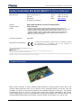
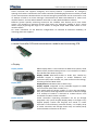
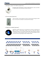
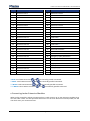
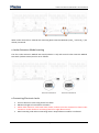
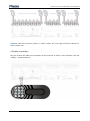
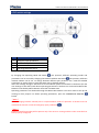
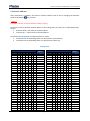
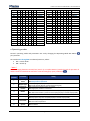
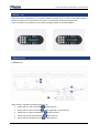
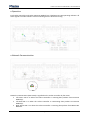
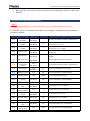
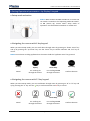
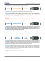
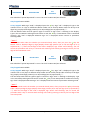
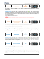
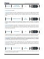
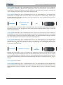
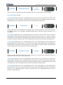
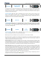
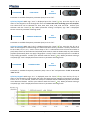
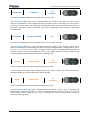
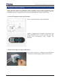
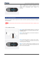
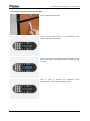
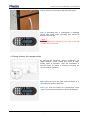
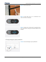
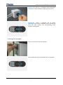
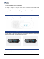
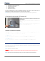
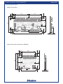
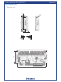
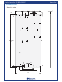
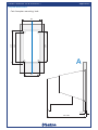
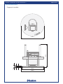
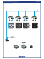
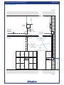
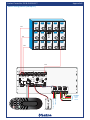
Locker Controller ELS & ELS SELECT Technical Manual Locker Controller ELS & ELS SELECT Technical Manual Table of contents Locker Controller ELS & ELS SELECT Technical Manual ........................................................................... 4 Product description ............................................................................................................................. 4 Basic Parts ........................................................................................................................................... 5 Locker Controller PCB with two extension modules and connecting PCB ..................................... 5 Display............................................................................................................................................. 5 Emergency Open Push-button (optional) ....................................................................................... 6 Coin acceptor (optional) ................................................................................................................. 6 Fingerprint module (optional) ........................................................................................................ 6 Connections ........................................................................................................................................ 6 Connecting Locker Extension Modules........................................................................................... 7 Locker Extension Module setting ................................................................................................... 8 Connecting Electronic Locks ........................................................................................................... 8 Display connection.......................................................................................................................... 9 Power supply connection (Locker Controller without distribution board) .................................. 10 Power supply connection (Locker Controller with distribution board) ........................................ 10 Metra NET Network connection (Locker Controller without distribution board) ........................ 11 Metra NET Network connection (Locker Controller with distribution board) ............................. 12 Coin Acceptor connection ............................................................................................................ 13 External emergency open pushbutton connection (optional) ..................................................... 13 DIP switch settings ............................................................................................................................ 14 Network address........................................................................................................................... 15 Operating modes .......................................................................................................................... 16 Power - on ......................................................................................................................................... 17 Signalization ...................................................................................................................................... 17 Power-on ...................................................................................................................................... 17 Operation ...................................................................................................................................... 18 Network Communication ............................................................................................................. 18 Actions and operating parameters ................................................................................................... 19 Setting Operational parameters – via Metra NET Network.............................................................. 20 Setting Operational parameters – by Display’s keypad .................................................................... 21 Setup mode activation .................................................................................................................. 21 Navigating thru menus with 4 key keypad ................................................................................... 21 Navigating thru menus with 12 key keypad ................................................................................. 21 Page 2 Locker Controller ELS & ELS SELECT Technical Manual Initiating actions and setting operating parameters .................................................................... 22 Emergency Open procedure ............................................................................................................. 31 Internal Emergency open pushbutton.......................................................................................... 31 External Emergency open pushbutton ......................................................................................... 31 Test mode of operation .................................................................................................................... 32 Test mode activation .................................................................................................................... 32 Testing electronic locks installation.............................................................................................. 33 Closing Lockers for transportation ............................................................................................... 34 Testing Emergency open pushbutton........................................................................................... 35 Testing Coin acceptor ................................................................................................................... 36 Erasing operating parameters ...................................................................................................... 37 Warning signalization ........................................................................................................................ 37 Alarm signalization ............................................................................................................................ 37 Checking of locker Alarm functionality ......................................................................................... 38 Expired/Blocked signalization ........................................................................................................... 38 Remote opening of single locker signalization................................................................................. 38 Functional Test .................................................................................................................................. 38 Checking locker wiring order (ELS Systems only) ......................................................................... 39 Locking / Unlocking of All Lockers ................................................................................................ 39 Device replacement .......................................................................................................................... 39 Maintenance ..................................................................................................................................... 40 Troubleshooting Guide ..................................................................................................................... 40 Technical data ................................................................................................................................... 40 Appendix ........................................................................................................................................... 41 Page 3 Locker Controller ELS & ELS SELECT Technical Manual Locker Controller ELS & ELS SELECT Technical Manual Manufacturer: Metra inženiring d.o.o. IOC Trzin Špruha 19 SI-1236 Trzin, Slovenia System: Product Group: Types: Metra ELS & ELS SELECT– Electronic Locking Systems Locker Controller Year of Construction: 2008-2011 Declaration of Conformity: phone: fax: web: +386 1 56 10 740 +386 1 56 10 744 www.metra.si LC16AELKP, LC16AESKP, LC16ELKP, LC16ESKP, LC24ELKP, LC24ESKP, LC32ELKP, LC32ESKP (Keypad) LC16AELIS, LC16AESIS, LC16ELIS, LC16ESIS, LC24ELIS, LC24ESIS, LC32ELIS, LC32ESIS (ISO 15693, ISO14443A/B) LC16AELLF, LC16AESLF, LC16ELLF, LC16ESLF, LC24ELLF, LC24ESLF, LC32ELLF, LC32ESLF (LF Multitag) LC16AELMF, LC16AESMF, LC16ELMF, LC16ESMF, LC24ELMF, LC24ESMF, LC32ELMF, LC32ESMF (Mifare) LC16AELSD, LC16AESSD, LC16ELSD, LC16ESSD, LC24ELSD, LC24ESSD, LC32ELSD, LC32ESSD (Skidata) LC08 (Locker Controller Extension Module) The Metra ELS & ELS SELECT products have been developed, designed and manufactured in accordance with the EU directive for Electromagnetic Compatibility (2004/108/EC). Locker Controller ELS & ELS SELECT Technical Manual [rev.0-140611] 2011 Metra inženiring d.o.o. All Rights reserved. No part of this manual may be reproduced in any form or by any means without prior written permission of Metra inženiring d.o.o. The contents of this manual are subject to change without notice. All efforts have been made to ensure the accuracy of the contents of this manual, however, should any errors be detected, Metra inženiring would greatly appreciate being informed of them. Metra inženiring d.o.o. can assume no responsibility for any errors in this manual. Product description Metra Locker Controller is used in different Metra Electronic Locking Systems. Device drives and monitors Metra Electronic Locks. Up to 16 locks can be connected directly to the unit, with the possibility to add up to two Extension Modules for 8 additional Electronic Locks each. This enables configurations for up to 16, 24 or 32 locks, which makes the controller adoptable to many locker layout configurations. As user interface different system specific Metra user interface devices (e.g. Display RFID/Keypad/Combo/Touch, Reader Terminal, Reader Terminal Basic, etc.) can be used. Page 4 Locker Controller ELS & ELS SELECT Technical Manual Locker Controller also supports emergency and security features. A pushbutton for emergency opening of all Lockers connected to the Locker Controller (and belonging extension modules) is fitted on the main electronics board and also an external emergency pushbutton can be connected. In case of attempt of break-in an Alarm message is distributed over Metra NET Network to Metra user interface devices and over Metra Network Controller to LAN / WAN and Metra software. Different (system specific) enhancing accessories are available: Euro deposit pad to limit locker misuse, coin acceptor to generate revenue from locker use, fingerprint module to lock / unlock lockers simply by placing the finger as an addition to Keypad and/or RFID media reader on user interface device. For easier installation on site different configurations of controller & extension module(s) on mounting plates are supplied. Basic Parts Locker Controller PCB with two extension modules and connecting PCB Display Display Combo Display RFID Display Keypad Metra Display RFID is a user interface for Metra ELS systems, while Metra Display Combo and Keypad are a user interfaces for Metra ELS and Metra ELS SELECT systems. Display Combo: Read RFID tickets as locker keys. Twelve key washable keypad is integrated to enable additional user interaction (PIN, locker number, etc.) and can be used for locking / unlocking instead of RFID media. Display RFID: Reads RFID tickets as locker keys. Display Keypad: Integrated 12 key washable keypad to enable user interaction (PIN, locker number, etc.). Each model shows the locker number on a four digit LED display. They also perform audio signalization and show an alarm message if an attempt of break-in is detected on a Metra Electric Lock connected to a Metra Locker Controller. Locker Controller’s operating parameters are set up through integrated 4 key system keypad (Display RFID) or through 12 key keypad (Display Combo and Keypad) and stored in Locker Controller’s internal battery powered memory. To simplify setup of Locker Controller and manage master keys and master/setup codes also Metra software can be used. Page 5 Locker Controller ELS & ELS SELECT Technical Manual Emergency Open Push-button (optional) Emergency Open Push-button is used to initiate Emergency Open procedure for all Electronic Locks connected to Locker Controller. Coin acceptor (optional) Locker Controller can be configured to ask for payment when locking the locker door. In that case Coin Acceptor is mounted near the Display. Fingerprint module (optional) Fingerprint module allows users to lock/unlock the locker by presenting the finger to sensor. It offers higher comfort for users as they don't need to remember PIN code or carry around the RFID media. When fingerprint module is connected to Locker Controller each user can freely choose whether he/she will lock the locker using fingerprint/PIN code/RFID media. Connections Page 6 Locker Controller ELS & ELS SELECT Technical Manual # description # description 1 Electronic Lock 1 27 Electronic Lock 27 2 Electronic Lock 2 28 Electronic Lock 28 3 Electronic Lock 3 29 Electronic Lock 29 4 Electronic Lock 4 30 Electronic Lock 30 5 Electronic Lock 5 31 Electronic Lock 31 6 Electronic Lock 6 32 Electronic Lock 32 7 Electronic Lock 7 33 Local CAN* 8 Electronic Lock 8 34 Local CAN* 9 Electronic Lock 9 35 BDM Loader 10 Electronic Lock 10 36 Local CAN** 11 Electronic Lock 11 37 Local CAN** 12 Electronic Lock 12 38 BDM Loader 13 Electronic Lock 13 39 COM (Not used) 14 Electronic Lock 14 40 Local CAN*** 15 Electronic Lock 15 41 Local CAN*** 16 Electronic Lock 16 42 Metra NET Network 17 Electronic Lock 17 43 Power**** 18 Electronic Lock 18 44 Power**** 19 Electronic Lock 19 45 Emergency open pushbutton 20 Electronic Lock 20 46 Coin acceptor 21 Electronic Lock 21 47 Reader (Not used) 22 Electronic Lock 22 48 Fingerprint module 23 Electronic Lock 23 49 Display 24 Electronic Lock 24 50 I2C (Not used) 25 Electronic Lock 25 51 BDM Loader 26 Electronic Lock 26 52 I2C (Not used) *NOTE: Local CAN connectors **NOTE: Local CAN connectors ***NOTE: Local CAN connectors and and and ****NOTE: 12V DC Power connectors are internally parallel connected. are internally parallel connected. are internally parallel connected. and are internally parallel connected. Connecting Locker Extension Modules When Locker Controller without mounting plate is used connect up to two Extension modules by 6 wire flat cable. There are two equivalent connectors on the main electronics board (LC16A) use the one which suits your connection best. Page 7 Locker Controller ELS & ELS SELECT Technical Manual When Locker Controller is ordered with mounting plate Extension Modules (LC24_* and LC32_*) are already connected. Locker Extension Module setting The first Locker Extension Module DIP switch (indexes 17-24) and second Locker Extension Module DIP switch (indexes 25-32) must be set as follows: Connecting Electronic Locks Connect Electronic Locks using 6 wire flat cables. Maximum length of each cable is 20 meters. Cables from Electronic Locks with lower locker numbers must be connected to lower index connector. Locker number is increasing from left to right (blue arrows)! Mind ascending order when numerating lockers. Gaps between numbers are allowed. Page 8 Locker Controller ELS & ELS SELECT Technical Manual EXAMPLE: Most left connector (index 1) is locker number 161, most right connector (index 32) is locker number 192. Display connection Plug the 10 wire flat cable from the Display to the connector as shown in the schematic. See also “Display – Technical Manual”. Page 9 Locker Controller ELS & ELS SELECT Technical Manual Power supply connection (Locker Controller without distribution board) Regulated 12 VDC power supply is required for proper operation. Connect as many units as possible to a single power supply unit. Consult the Technical Specifications section of this document for current consumption. There are two internally connected power connectors on the board. You can use one as “Power IN” and the other as “Power OUT” connector. Connect 12V DC regulated power supply to designated terminals. The terminals are marked as +12V for positive connection and GND for ground connection. WARNING Mind the polarity! Wrong polarity could result in irreparable damage to the device. Respect power requirements data! Using unsuitable power supply could result in damage to the power supply and to the device. Power supply connection (Locker Controller with distribution board) Regulated 12 VDC power supply is required for proper operation. Connect as many units as possible to a single power supply unit. Consult the Technical Specifications section of this document for current consumption. Connect 12V DC regulated power supply to designated terminals. The terminals are marked as +12V for positive connection and GND for ground connection. WARNING Mind the polarity! Wrong polarity could result in irreparable damage to the device. Respect power requirements data! Using unsuitable power supply could result in damage to the power supply and to the device. Page 10 Locker Controller ELS & ELS SELECT Technical Manual Metra NET Network connection (Locker Controller without distribution board) The Metra NET Network connection provides for operational functionality of the Locker Controller. Different devices in parallel can be connected to the Metra Network Controller by a single unshielded twisted pair (UTP) cable. Total length of the twisted pair cable is limited to 1 km. One Network Line Terminator must be connected at the far end of the network cable. See also “Metra NET Network – Installation Manual” for different wiring schemes. Connect the twisted pair network cable to designated terminals. The terminals are marked as CANLO for network low signal and CANHI for network high signal. NOTE Mind the polarity of the network connection! Page 11 Locker Controller ELS & ELS SELECT Technical Manual Metra NET Network connection (Locker Controller with distribution board) Connect the twisted pair network cable to designated terminals. The terminals are marked as CANL for network low signal and CANH for network high signal. NOTE Mind the polarity of the network connection! Page 12 Locker Controller ELS & ELS SELECT Technical Manual Coin Acceptor connection Connect the Coin acceptor to designated terminals as shown in the schematic. External emergency open pushbutton connection (optional) Connect the blue and blue/white wires of the UTP cable from the Emergency open pushbutton to designated terminals as shown in the schematic. Page 13 Locker Controller ELS & ELS SELECT Technical Manual DIP switch settings # description 1 Emergency open pushbutton 2 Parameters request button 3 Network Address DIP switch 4 Operating Mode DIP Switch By changing the Operating Mode DIP Switch pins positions, different operating modes and parameters can be set and by changing the Network Address DIP Switch pins positions, different network address can be set. To change between different pins positions, use a small flat headed screwdriver or similar object to push DIP switch pins to desired position. After each settings change or after device’s first installation power off and back on the device (for the new settings to take effect) and obtain operating parameters if the device is connected to Metra NET Network controlled by Metra Network Controller and Metra SW. Operating parameters are obtained through the Metra NET Network. The server must be set up and running for that purpose. To obtain operating parameters, press the PARAMETERS REQUEST button. NOTE Before changing between Normal/Test or ELS/ELS SELECT mode of operation all lockers must be unlocked via external or internal emergency open pushbutton . NOTE Network based functionality will be present only if the server is running and the Locker Controller has been properly configured. Page 14 Locker Controller ELS & ELS SELECT Technical Manual Network address After installation is complete, the device’s network address must be set by changing the Network Address DIP Switch pins positions. NOTE Each Metra device must have different address setting. Look up the code for desired network address in the coding table. Set switch #1 to indicated position, where: 0 (switch down) = No offset in network address. 1 (switch up) = “+600” offset in network address. Set switches #2 through #8 to indicated positions, where: 0 indicates the corresponding switch is in OFF position (switch down) 1 indicates the corresponding switch is in ON position (switch up) Coding table: 1 0/1 0/1 0/1 0/1 0/1 0/1 0/1 0/1 0/1 0/1 0/1 0/1 0/1 0/1 0/1 0/1 0/1 0/1 0/1 0/1 0/1 0/1 0/1 0/1 0/1 0/1 0/1 0/1 0/1 0/1 0/1 switch positions 2 3 4 5 6 0 0 0 0 0 0 0 0 0 0 0 0 0 0 0 0 0 0 0 0 0 0 0 0 1 0 0 0 0 1 0 0 0 0 1 0 0 0 0 1 0 0 0 1 0 0 0 0 1 0 0 0 0 1 0 0 0 0 1 0 0 0 0 1 1 0 0 0 1 1 0 0 0 1 1 0 0 0 1 1 0 0 1 0 0 0 0 1 0 0 0 0 1 0 0 0 0 1 0 0 0 0 1 0 1 0 0 1 0 1 0 0 1 0 1 0 0 1 0 1 0 0 1 1 0 0 0 1 1 0 0 0 1 1 0 0 0 1 1 0 0 0 1 1 1 0 0 1 1 1 0 0 1 1 1 7 0 0 1 1 0 0 1 1 0 0 1 1 0 0 1 1 0 0 1 1 0 0 1 1 0 0 1 1 0 0 1 8 0 1 0 1 0 1 0 1 0 1 0 1 0 1 0 1 0 1 0 1 0 1 0 1 0 1 0 1 0 1 0 address 1 0/1 0/1 0/1 0/1 0/1 0/1 0/1 0/1 0/1 0/1 0/1 0/1 0/1 0/1 0/1 0/1 0/1 0/1 0/1 0/1 0/1 0/1 0/1 0/1 0/1 0/1 0/1 0/1 0/1 0/1 0/1 1/601 2/602 3/603 4/604 5/605 6/606 7/607 8/608 9/609 10/610 11/611 12/612 13/613 14/614 15/615 16/616 17/617 18/618 19/619 20/620 21/621 22/622 23/623 24/624 25/625 26/626 27/627 28/628 29/629 30/630 31/631 Page 15 switch positions 2 3 4 5 6 0 1 1 0 0 0 1 1 0 0 0 1 1 0 1 0 1 1 0 1 0 1 1 0 1 0 1 1 0 1 0 1 1 1 0 0 1 1 1 0 0 1 1 1 0 0 1 1 1 0 0 1 1 1 1 0 1 1 1 1 0 1 1 1 1 0 1 1 1 1 1 0 0 0 0 1 0 0 0 0 1 0 0 0 0 1 0 0 0 0 1 0 0 0 1 1 0 0 0 1 1 0 0 0 1 1 0 0 0 1 1 0 0 1 0 1 0 0 1 0 1 0 0 1 0 1 0 0 1 0 1 0 0 1 1 1 0 0 1 1 1 0 0 1 1 1 0 0 1 1 1 0 1 0 0 7 1 1 0 0 1 1 0 0 1 1 0 0 1 1 0 0 1 1 0 0 1 1 0 0 1 1 0 0 1 1 0 8 0 1 0 1 0 1 0 1 0 1 0 1 0 1 0 1 0 1 0 1 0 1 0 1 0 1 0 1 0 1 0 address 51/651 52/652 53/653 54/654 55/655 56/656 57/657 58/658 59/659 60/660 61/661 62/662 63/663 64/664 65/665 66/666 67/667 68/668 69/669 70/670 71/671 72/672 73/673 74/674 75/675 76/676 77/677 78/678 79/679 80/680 81/681 Locker Controller ELS & ELS SELECT Technical Manual 0/1 0/1 0/1 0/1 0/1 0/1 0/1 0/1 0/1 0/1 0/1 0/1 0/1 0/1 0/1 0/1 0/1 0/1 0/1 0 0 0 0 0 0 0 0 0 0 0 0 0 0 0 0 0 0 0 0 1 1 1 1 1 1 1 1 1 1 1 1 1 1 1 1 1 1 1 0 0 0 0 0 0 0 0 0 0 0 0 0 0 0 0 1 1 1 0 0 0 0 0 0 0 0 1 1 1 1 1 1 1 1 0 0 1 0 0 0 0 1 1 1 1 0 0 0 0 1 1 1 1 0 0 1 0 0 1 1 0 0 1 1 0 0 1 1 0 0 1 1 0 0 1 0 1 0 1 0 1 0 1 0 1 0 1 0 1 0 1 0 1 32/632 33/633 34/634 35/635 36/636 37/637 38/638 39/639 40/640 41/641 42/642 43/643 44/644 45/645 46/646 47/647 48/648 49/649 50/650 0/1 0/1 0/1 0/1 0/1 0/1 0/1 0/1 0/1 0/1 0/1 0/1 0/1 0/1 0/1 0/1 0/1 0/1 0/1 1 1 1 1 1 1 1 1 1 1 1 1 1 1 1 1 1 1 0 0 0 0 0 0 0 0 0 0 0 0 0 0 0 1 1 1 1 1 1 1 1 1 1 1 1 1 1 1 1 1 1 0 0 0 0 0 0 0 0 0 0 1 1 1 1 1 1 1 1 0 0 0 0 0 0 1 1 1 1 0 0 0 0 1 1 1 1 0 0 0 0 1 1 0 0 1 1 0 0 1 1 0 0 1 1 0 0 1 1 0 1 0 1 0 1 0 1 0 1 0 1 0 1 0 1 0 82/682 83/683 84/684 85/685 86/686 87/687 88/688 89/689 90/690 91/691 92/692 93/693 94/694 95/695 96/696 97/697 98/698 99/699 Operating modes Device’s operating mode and parameters are set by changing the Operating Mode DIP Switch pins positions. Set switches #1 through #8 to indicated positions, where: OFF = switch down ON = switch up NOTE Before changing between Normal/Test (switch 7) or ELS/ELS SELECT (switch 8) mode of operation all lockers must be unlocked via external or internal emergency open pushbutton . switch positions parameter setting 1 Operating mode 2 Keypad type 3 Fingerprint module 4 Reader 5 - 6 Special Keys 7 TEST mode 8 System OFF: Normal operating mode ON: Setup mode of operation OFF: 4 key keypad (Display RFID) ON: 12 key keypad (Display Combo & Display Keypad) OFF: Fingerprint module in NOT connected ON: Fingerprint module is connected OFF: RFID media reader is not present in the Display (Display Keypad) ON: RFID media reader is present in the Display (Display Combo & Display RFID) Not used; Must be set to OFF. OFF:RFID media is accepted as user key (Display Combo & Display RFID) ON: Only special keys are accepted (Display Combo & Display RFID) OFF: Normal operating mode ON: Test mode of operation OFF: ELS ON: ELS SELECT Page 16 Locker Controller ELS & ELS SELECT Technical Manual Power - on After the device is powered on, its network address (number from 1 to 99 or from 600 to 699) is shown on Display for a few seconds. This feature is intended for maintenance personnel. NOTE: If payment is turned ON, current Saldo is displayed after the network address. Signalization Power-on When power is applied the following LEDs are on: Yellow LED on Locker Controller (12VDC present) Green LED on Locker Controller (5VDC regulated on board active) Yellow LED on Extension Module(s) (12VDC present) Green LED on Extension Module(s) (5VDC present) Green LED on distribution board (12VDC present) Page 17 Locker Controller ELS & ELS SELECT Technical Manual Operation Each Locker Controller and Locker Extension Module has a blinking green LED operating indicator. All these signals are under software control indicating that the device is running. Network Communication Network communication (Metra NET) is signalled on the Locker Controller by four LEDs: Left Green LED is on when the Locker Controller is receiving data packets from Extension Module(s). Left Red LED is on when the Locker Controller is transmitting data packets to Extension Module(s). Right Green LED is on when the Locker Controller is receiving data packets from Metra NET Network. Page 18 Locker Controller ELS & ELS SELECT Technical Manual Right Red LED is on when the Locker Controller is transmitting data packets to Metra NET Network. Actions and operating parameters NOTE Some operating parameters are system dependant and may not be available in your system. For detailed actions and parameters descriptions see paragraph “Setting Operational parameters – by Display’s keypad”. action / parameter System default value short description / values dEFP Default parameters ELS ELS SELECT - nLOC Number of Lockers ELS ELS SELECT 32 Number of connected lockers. Can be set to 1, 2, 3,...32. SLOC Starting locker number ELS ELS SELECT 1 Number of first connected locker. Can be set to 1, 2, 3,...7999. CodE Master Code* ELS ELS SELECT - Has 5 sub-parameters: up to 5 master codes can be stored in. SCod Setting Code* ELS ELS SELECT - Has 5 sub-parameters: up to 5 setup codes can be stored in. Add Add Master Key* ELS ELS SELECT - Up to 5 Master Cards can be stored in. ErAS Erase all special keys and PIN codes* ELS ELS SELECT - Erases all Master/Setup Codes and Master keys. Aud Audio Signal ELS ELS SELECT On Can be activated (On) or silent (OFF). En-A Multiple locking ELS OFF Can be enabled (On) or disabled (OFF). GrUP PIN code for multiple locking ELS 8000 Visible only if multiple locking is enabled (On). Can be set to: 8000 to 9999. EOPn Emergency opening ELS ELS SELECT OFF Can be enabled (On) or disabled (OFF). AOPn Auto opening ELS OFF Can be set to: OFF (0), 1, 2, 3,...9999. USr User Waiting time ELS ELS SELECT 5 Can be set to 1, 2, 3,...8 seconds. USI User Waiting time increment ELS 2 Can be set to 1, 2, 3 or 4 seconds. PinL Minimal PIN Length ELS ELS SELECT 1 Can be set to 1, 2, 3, 4 or 5. PinC Pin/Code Request display ELS ELS SELECT Pin Can be set to “Pin” or “COdE”. LEu Locker level ELS OFF Can be set to OFF, 1, 2, 3 or 4. LAC Locker active time ELS SELECT 30 Can be set to 30, 31, 32,...240 seconds dISP Occupied Locker signalisation ELS OFF Can be enabled (On) or disabled (OFF). Page 19 Resets all parameters to factory default values. Locker Controller ELS & ELS SELECT Technical Manual LIS White List ELS OFF Can be enabled (On) or disabled (OFF). PAY Payment ELS ELS SELECT OFF Can be set to OFF, On, Sign or bLOC. P Co Coin Value** ELS ELS SELECT 1.00 Can be set to 0.10, 0.20, 0.25, 0.50, 1.00, 2.00 or 5.00. P dU Tenancy Duration** ELS ELS SELECT 8h Can be set to OFF, 0 h, 1 h, 2 h,...24 h. P LI Payment Limit** ELS ELS SELECT 1 Visible only if Tenancy duration is not set to “OFF” or “0”. Can be set to 1, 2, 3,...31. P dS Currency** ELS ELS SELECT Euro Can be set to “Euro”, “Coin”, “GbP”, “PAY”, “USd” or “CHF”. L dU Locking duration*** ELS 8h Can be set to 1 h, 2 h, 3h,...24 h. SALd Display Saldo ELS ELS SELECT - Displays sum of all inserted coins. SALE Erase Saldo ELS ELS SELECT - Resets coin counter. *Not avaliable if “Special Keys Mode” is set to “On-line” in Metra ELS/LCC software. **Avaliable only if payment parameter is set to “On”. ***Avaliable only if payment parameter is set to “Sign” or “bLOC”. Setting Operational parameters – via Metra NET Network Metra Network Controller must be connected to Metra NET Network Metra server must be running and all hardware added in Metra ELS/ELS NET/LCC NET software. Each Locker Controller must have set its unique Metra NET Network address – ID. OPTION 1 (downloading parameters to single divice at a time): By pressing the PARAMETERS REQUEST button on the Locker Controller you trigger the request for operating parameters. Operating parameters are downloaded to the Locker Controller. Check if correct operating parameters were downloaded. See chapter “Functional Test” for more details OPTION 2 (downloading parameters to all devices at once): In Metra SW go to View\Download and click on the “Download All” button. Operating parameters are downloaded to all devices in the Metra NET Network. Check if correct operating parameters were downloaded. See chapter “Functional Test” for more details Page 20 Locker Controller ELS & ELS SELECT Technical Manual Setting Operational parameters – by Display’s keypad Setup mode activation STEP 1: With small flat headed screwdriver or similar tool set switch 1 located on the “Operating mode DIP switch” to ON (switch up). Device enters setup mode of operation. Use flat headed screwdriver or similar tool. Navigating thru menus with 4 key keypad When you enter Setup mode, you can scroll down through menu by pressing on “down arrow” key and up by pressing the “up arrow” key. Use the “Enter” key to confirm selection and “Esc” key to cancel. NOTE: To accelerate scrolling up/down thru the menus hold the “up/down arrow” key pressed. Esc Key Up Key Down Keys Enter Key Cancel For scrolling UP through the menus. For scrolling DOWN through the menus. Confirm selection Navigating thru menus with 12 key keypad When you enter Setup mode, you can scroll down through menu by pressing on “8” or “0” key and up by pressing the “2” key. Use the key to confirm selection and key to cancel. and Key UP Key Down Keys Key Cancel For scrolling UP through the menus. For scrolling DOWN through the menus. Confirm selection Page 21 Locker Controller ELS & ELS SELECT Technical Manual Initiating actions and setting operating parameters ACTION ELS ELS SELECT DEFAULT PARAMETERS Action erases all current parameter values and sets them back to factory default. 4/12 key keypad: While sign “dEFP” is displayed press the “Enter”/ key. “ConF” is displayed and blinking. Press and hold the “Enter”/ key for a few seconds to confirm or press “Esc”/ key to cancel. When action is accepted, sign “YES” is displayed and all parameters are set back to default values. Device returns to parameter selecting mode. NOTE If the Fingerprint module is connected to the device, signs “ErAS”, followed by “FP” are displayed before “YES”. PARAMETER ELS ELS SELECT NUMBER OF LOCKERS 4 key keypad: While sign “nLOC” is displayed press the “Enter” key. Press the key for up or down on the Keypad to increase or decrease the number of connected lockers. Number can be set from 1 to 32. Confirm your selection with the “Enter” key. When parameter setting is accepted, sign “YES” is displayed. Device returns to parameter selecting mode. 12 key keypad: While sign “nLOC” is displayed press the key. With digit keys on the Keypad enter the number of connected lockers. Numbers from 1 to 32 are accepted. Confirm your selection with the key. When parameter setting is accepted, sign “YES” is displayed. Device returns to parameter selecting mode. PARAMETER STARTING LOCKER NUMBER ELS ELS SELECT 4 key keypad: While sign “SLOC” is displayed press the “Enter” key. Press the key for up or down on the Keypad to increase or decrease the number of the first connected locker. First locker number can be set from 1 to 8000-nLOC*. Confirm your selection with the “Enter” key. When parameter setting is accepted, sign “YES” is displayed. Device returns to parameter selecting mode. 12 key keypad: While sign “SLOC” is displayed press the key. With digit keys on the Keypad enter the number of the first connected locker. First locker number can be set from 1 to 8000-nLOC*. Confirm your selection with the key. When parameter setting is accepted, sign “YES” is displayed. Device returns to parameter selecting mode. *Example: If nLOC=8, SLOC can be set from 1 to 7992. Page 22 Locker Controller ELS & ELS SELECT Technical Manual PARAMETER ELS ELS SELECT MASTER CODE Not avaliable if “Special Keys Mode” is set to “On-line” in Metra ELS/LCC software. 4 key keypad: Not available. 12 key keypad: While sign “CodE” is displayed press the key. Sign “nbr” is displayed. Type in the number from 1 to 5 (Up to 5 different Master Codes can be stored). Master Code can be up to 16 digits long. Display shows digit position (01 to 16) and digit (0 to 9) separated by “-“. The new Master Code must be typed in again to confirm it. Sign “ConF” is flashing on the display. Type in the new Master Code again and confirm it with the key. If new Master Code is confirmed correctly, sign “YES” is displayed otherwise sign “no” is displayed. Device returns to parameter selecting mode. NOTE If the Master Code under the number you entered already exists, after you press the key the Master Code is displayed digit by digit (Display shows digit position (01 to 16) and digit (0 to 9) separated by “-“). After the last digit of the code is displayed, sign “CodE” starts flashing. You can cancel the procedure with key or continue with entering new code by pressing on the key for first digit of the new Master Code. PARAMETER ELS ELS SELECT SETUP CODE Not avaliable if “Special Keys Mode” is set to “On-line” in Metra ELS/LCC software. 4 key keypad: Not available. 12 key keypad: While sign “SCod” is displayed press the key. Sign “nbr” is displayed. Type in the number from 1 to 5 (Up to 5 different Setup Codes can be stored). Setup Code can be up to 16 digits long. Display shows digit position (01 to 16) and digit (0 to 9) separated by “-“. The new Setup Code must be typed in again to confirm it. Sign “ConF” is flashing on the display. Type in the new Setup Code again and confirm it with the key. If new Setup Code is confirmed correctly, sign “YES” is displayed otherwise sign “no” is displayed. Device returns to parameter selecting mode. NOTE If the Setup Code under the number you entered already exists, after you press the key the Setup Code is displayed digit by digit (Display shows digit position (01 to 16) and digit (0 to 9) separated by “-“). After the last digit of the code is displayed, sign “SCod” starts flashing. You can cancel the procedure with key or continue with entering new code by pressing on the key for first digit of the new Setup Code. Page 23 Locker Controller ELS & ELS SELECT Technical Manual ACTION ELS ELS SELECT MASTER KEY Not avaliable if “Special Keys Mode” is set to “On-line” in Metra ELS/LCC software or you are using Display Keypad. 4/12 key keypad: While sign “Add” is displayed press the “Enter”/ key. Time countdown starts (vertical lines are displayed) and interrupted beep acoustic signal is activated. Present a RFID media that you want to use as a Master key. After the RFID media is recodnized and stored as a Master Key time countdown restarts. Up to 5 Master keys can be stored in. NOTE If any RFID media is presented and time countdown ends, device returns to Setup menu. ACTION ERASE ALL SPECIAL KEYS AND PIN CODES ELS ELS SELECT Not avaliable if “Special Keys Mode” is set to “On-line” in Metra ELS/LCC software. This erases all Master/Setup codes and Master keys. 4/12 key keypad: While sign “ErAS” is displayed press the “Enter”/ key. “ConF” is displayed and blinking. Press and hold the “Enter”/ key for a few seconds to confirm or press “Esc”/ key to cancel. When action is accepted, sign “YES” is displayed and all Master/Setup codes and Master keys are erased. Device returns to parameter selecting mode. PARAMETER ELS ELS SELECT AUDIO SIGNAL 4/12 key keypad: While sign “Aud” is displayed press the “Enter”/ key. Press the key for up or down on the Keypad to activate (On) or to deactivate - silent (OFF) the audio signalling. Confirm your selection with the “Enter”/ key. When parameter setting is accepted, sign “YES” is displayed. Device returns to parameter selecting mode. PARAMETER MULTIPLE LOCKING ELS If set to On, Multiple locking with PIN Code is enabled. 4 key keypad: Not available. 12 key keypad: While sign “En-A” is displayed press the key. Press the key for up or down on the Keypad to enable (On) or to disable (OFF) multiple locking. Confirm your selection with the key. When parameter setting is accepted, sign “YES” is displayed. Device returns to parameter selecting mode. Page 24 Locker Controller ELS & ELS SELECT Technical Manual PARAMETER PIN CODE FOR MULTIPLE LOCKING ELS PIN Code that activates multiple locking with PIN Code. 4 key keypad: Not available. 12 key keypad: While sign “GrUP” is displayed press the key. Type-in the 4 digit number from 8000 to 9999. This will be the new group PIN code for this device. Confirm your selection with the key. When parameter setting is accepted, sign “YES” is displayed. Device returns to parameter selecting mode. PARAMETER ELS ELS SELECT EMERGENCY OPENING Remote emergency opening can be activated by pressing a button connected to the Network Controller (or by a Timetable). Each Metra Locker Controller can be set to enable or disable this feature. 4/12 key keypad: While sign “EOPn” is displayed press the “Enter”/ key. Press the key for up or down on the Keypad to enable (On) or to disable (OFF) emergency opening. Confirm your selection with the “Enter”/ key. When parameter setting is accepted, sign “YES” is displayed. Device returns to parameter selecting mode. PARAMETER AUTO OPENING ELS Automatic opening can be set to open all lockers connected to the device after desired time. Time can be set in minutes from 1 to 9999 minutes. If 0 is selected then automatic opening is turned OFF. 4 key keypad: While sign “AOPn” is displayed press the “Enter” key. Press the key for up or down on the Keypad to increase or decrease automatic opening time. Time can be set to: OFF, 1, 2, 3,...9999 in 1 second steps. Confirm your selection with the “Enter” key. When parameter setting is accepted, sign “YES” is displayed. Device returns to parameter selecting mode. 12 key keypad: While sign “AOPn” is displayed press the key. With digit keys on the Keypad enter desired time in minutes. If you want to disable (OFF) automatic opening, enter 0. Confirm your selection with the key. When parameter setting is accepted, sign “YES” is displayed. Device returns to parameter selecting mode. PARAMETER ELS ELS SELECT USER WAITING TIME After the Locker door is closed, system waits for RFID media / finger to be presented or PIN code entered, for chosen number of seconds. Page 25 Locker Controller ELS & ELS SELECT Technical Manual 4 key keypad: While sign “USr” is displayed press the “Enter” key. Press the key for up or down on the Keypad to increase or decrease user waiting time. Time can be set from 2 to 8 seconds in 1 second steps. Confirm your selection with the “Enter” key. When parameter setting is accepted, sign “YES” is displayed. Device returns to parameter selecting mode. 12 key keypad: While sign “USr” is displayed press the key. With digit keys on the Keypad enter desired time in seconds. Time can be set from 2 to 8 seconds in 1 second steps. Confirm your selection with the key. When parameter setting is accepted, sign “YES” is displayed. Device returns to parameter selecting mode. PARAMETER USER WAITING TIME INCREMENT ELS User waiting time increments (slower countdown) after the countdown ended without presenting the ticket to lock the locker. This gives user more time to present the RFID media / finger or enter PIN code in second attempt. 4 key keypad: While sign “USI” is displayed press the “Enter” key. Press the key for up or down on the Keypad to increase or decrease user waiting time increment. Time can be set from 1 to 4 seconds in 1 second steps. Confirm your selection with the “Enter” key. When parameter setting is accepted, sign “YES” is displayed. Device returns to parameter selecting mode. 12 key keypad: While sign “USI” is displayed press the key. With digit keys on the Keypad enter desired time in seconds. Time can be set from 1 to 4 seconds in 1 second steps. Confirm your selection with the key. When parameter setting is accepted, sign “YES” is displayed. Device returns to parameter selecting mode. PARAMETER ELS ELS SELECT MINIMAL PIN LENGTH Minimal PIN code length is set to 1 by default. This means that someone can close the locker with minimal 1 digit or maximal 4 digits PIN code. This parameter can be also set up to 2, 3, 4 or 5. If set to 4, only 4 digit PIN codes are accepted. If set to 5, only 4 digit PIN codes are accepted and last (fourth) digit entered automatically confirms the entered PIN code and there is no need to press the key to confirm. 4 key keypad: Not available. 12 key keypad: While sign “PinL” is displayed press the key. With digit keys on the Keypad enter desired minimal PIN Code length (from 1 to 4) for this Device. Confirm your selection with the key. When parameter setting is accepted, sign “YES” is displayed. Device returns to parameter selecting mode. Page 26 Locker Controller ELS & ELS SELECT Technical Manual PARAMETER ELS ELS SELECT PIN REQUEST DISPLAY After the Locker is closed and Pin code requested, sign “Pin” or sign “COdE” can be displayed. 4 key keypad: Not available. 12 key keypad: While sign “PinC” is displayed press the key. Press the key for up or down on the Keypad to select “Pin” or “COdE”. Confirm your selection with the key. When parameter setting is accepted, sign “YES” is displayed. Device returns to parameter selecting mode. PARAMETER LOCKER LEVEL ELS Exactly one locker can be locked with one RFID media on each level (group). Locker lever can be set to 4 different levels or as standalone. Standalone (OFF) means, that each Locker Controller is in its own group. 4 key keypad: While sign “LEu” is displayed press the ”Enter” key. Press the key for up or down on the Keypad to select desired locker level. Locker level can be set to OFF, 1, 2, 3 and 4. If OFF is selected locker level function is disabled (OFF). Confirm your selection with the “Enter” key. When parameter setting is accepted, sign “YES” is displayed. Device returns to parameter selecting mode. 12 key keypad: While sign “LEu” is displayed press the key. With digit keys on the Keypad enter desired locker level. Values from 0, 1, 2, 3 and 4 are accepted. If 0 is entered, locker level function is disabled (OFF). Confirm your selection with the key. When parameter setting is accepted, sign “YES” is displayed. Device returns to parameter selecting mode. PARAMETER LOCKER ACTIVE TIME ELS SELECT Locker controller waits for Locker door to be closed for X seconds after successful Locker hire procedure. X can be set from 30 to 240 seconds. 4 key keypad: While sign “LAC” is displayed press the “Enter” key. Press the key for up or down on the Keypad to increase or decrease desired locker active time in seconds. Time can be set from 30 to 240 seconds in 1 second steps. Confirm your selection with the “Enter” key. When parameter setting is accepted, sign “YES” is displayed. Device returns to parameter selecting mode. 12 key keypad: While sign “LAC” is displayed press the key. With digit keys on the Keypad enter desired locker active time in seconds. Values from 30 to 240 are accepted. Confirm your selection with the key. When parameter setting is accepted, sign “YES” is displayed. Device returns to parameter selecting mode. Page 27 Locker Controller ELS & ELS SELECT Technical Manual PARAMETER OCCUPEID LOCKER SIGNALIZATION ELS This feature can be viewed as information for user which locker was locked by her/his RFID media and where to go to open it. If the RFID media is presented and recognized as a locker key on different device the locker number is flashing on the display and interrupted acoustic signal is activated. Locker remains closed. 4/12 key keypad: While sign “dISP” is displayed press the “Enter”/ key. Press the key for up or down on the Keypad to activate (On) or to deactivate (OFF) the occupied locker signalization. Confirm your selection with the “Enter”/ key. When parameter setting is accepted, sign “YES” is displayed. Device returns to parameter selecting mode. PARAMETER WHITE LIST ELS 4/12 key keypad: While sign “LIS” is displayed press the “Enter”/ key. Press the key for up or down on the Keypad to activate (On) or to deactivate (OFF) the white list checking. Confirm your selection with the “Enter”/ key. When parameter setting is accepted, sign “YES” is displayed. Device returns to parameter selecting mode. PARAMETER ELS ELS SELECT PAYMENT 4/12 key keypad: While sign “PAY” is displayed press the “Enter”/ key. Press the key for up or down on the Keypad to select one of the following options: OFF: Payment device is disabled. No tenancy limitations once the Locker is locked. On: Payment device is enabled. Four additional sub-parameters are accessible in parameter selecting mode. Set them regarding your Coin Acceptor (currency and value of used coins), number of additional payment(s), and required tenancy time. SIGn: (ELS only) Payment device is disabled. After the Locker is locked and tenancy expired, Locker expired signalization is turned on (two middle dots on the Display start flashing alternately). When all the Lockers with expired tenancy are unlocked, expired signalization is turned off. Also an additional tenancy time sub-parameter is accessible in parameter selecting mode and must be set. bLOC: (ELS only) Payment device is disabled. After the Locker is locked and tenancy expired, Locker becomes blocked and expired signalization is turned on (two middle dots on the Display start flashing alternately). Blocked Locker can be unlocked only in Master mode or with Emergency Open and cannot be unlocked by user with corresponding PIN code, RFID media or fingerprint. When all the blocked Lockers are unlocked, expired signalization is turned off. Also an additional tenancy time subparameter is accessible in parameter selecting mode and must be set. Confirm your selection with the “Enter”/ key. When parameter setting is accepted, sign “YES” is displayed. Device returns to parameter selecting mode. Page 28 Locker Controller ELS & ELS SELECT Technical Manual PARAMETER ELS ELS SELECT COIN VALUE Parameter is available if Payment parameter (PAY) is set to “On”. 4/12 key keypad: While sign “P Co” is displayed press the “Enter”/ key. Press the key for up or down on the Keypad to scroll through the menu and select coin value according your coin acceptor. Coin values that can be selected are: 0.10, 0.20, 0.25, 0.50, 1.00, 2.00 and 5.00. Confirm your selection with the “Enter”/ key. When parameter setting is accepted, sign “YES” is displayed. Device returns to parameter selecting mode. PARAMETER ELS ELS SELECT TENANCY DURATION Parameter is available if Payment parameter (PAY) is set to “On”. 4/12 key keypad: While sign “P dU” is displayed press the “Enter”/ key. Press the key for up or down on the Keypad to scroll through the menu and select tenancy duration. Tenancy duration can be set to OFF, 0 h, 1 h, 2 h,...24 h in 1 hour steps. If “0 h” is selected there are no limits once locker is paid, same Locker can be locked and unlocked (with same Pin Code or RFID media) any time without payment (functionally does not apply if fingerprint is used). If OFF is selected payment is needed on every locking procedure. Confirm your selection with the “Enter”/ key. When parameter setting is accepted, sign “YES” is displayed. Device returns to parameter selecting mode. PARAMETER ELS ELS SELECT PAYMENT LIMIT Parameter is available if Payment parameter (PAY) is set to “On” and parameter “P dU” is not set to “OFF” or “0”. 4/12 key keypad: While sign “P LI” is displayed press the “Enter”/ key. Press the key for up or down on the Keypad to scroll through the menu and payment limit. Number of payments can be set from 1 to 31. If 1 is selected, locker can always be unlocked without additional payment and locker never becomes blocked. Confirm your selection with the “Enter”/ key. When parameter setting is accepted, sign “YES” is displayed. Device returns to parameter selecting mode. Page 29 Locker Controller ELS & ELS SELECT Technical Manual PARAMETER ELS ELS SELECT CURRENCY Parameter is available if Payment parameter (PAY) is set to “On”. 4/12 key keypad: While sign “P dS” is displayed press the “Enter”/ key. Press the key for up or down on the Keypad to scroll through the menu and select currency according your coin acceptor. Currency can be set to Euro, Coin, GbP, PAY, USd and CHF. Confirm your selection with the “Enter”/ key. When parameter setting is accepted, sign “YES” is displayed. Device returns to parameter selecting mode. PARAMETER LOCKING DURATION ELS Parameter is available if Payment parameter (PAY) is set to “bLOC” or “Sign”. 4/12 key keypad: While sign “L dU” is displayed press the “Enter”/ key. Press the key for up or down on the Keypad to scroll through the menu and select locking duration. Locking duration can be set to 1 h, 2 h,...24 h in 1 hour steps. If locking duration expires expired/blocked signalization is turned on. Confirm your selection with the “Enter”/ key. When parameter setting is accepted, sign “YES” is displayed. Device returns to parameter selecting mode. ACTION ELS ELS SELECT DISPLAY SALDO Action is available only if Payment parameter (PAY) set to “PAY”. 4/12 key keypad: While sign “SALd” is displayed press the “Enter”/ key. Sum of all inserted coins is displayed and device returns to parameter selecting mode. ACTION ELS ELS SELECT ERASE SALDO Action is available only if Payment parameter (PAY) set to “PAY”. 4/12 key keypad: While sign “SALE” is displayed press the “Enter”/ key. “ConF” is displayed and blinking. Press and hold the “Enter”/ key for a few seconds to confirm or press “Esc”/ key to cancel. When action is accepted, sign “YES” is displayed and saldo is erased. Device returns to parameter selecting mode. Page 30 Locker Controller ELS & ELS SELECT Technical Manual Emergency Open procedure Locker Controller features an Emergency Open procedure, which unlocks all Electronic Locks connected to the Locker Controller and to all of the attached Locker Extension Modules. Locks are unlocked one by one, starting at the lock connected to the leftmost connector (position #1). Internal Emergency open pushbutton STEP 1: Press the Emergency open pushbutton. “EOPn” is displayed and all lockers connected to the Locker Controller start to unlock and open one after another and corresponding locker numbers are displayed. External Emergency open pushbutton STEP 1: Turn the key on emergency open pushbutton clockwise to initiate emergency opening of all Lockers. Page 31 Locker Controller ELS & ELS SELECT Technical Manual “EOPn” is displayed and all lockers connected to the Locker Controller start to unlock and open one after another and corresponding locker numbers are displayed. Test mode of operation While still In Normal mode of operation all lockers should be opened by pressing the Emergency open pushbutton. NOTE Alarm will be initiated when Locker Controller is put back to Normal mode if locker is opened in Test mode. Test mode activation STEP 1: With small flat headed screwdriver or similar tool set switch 7 located on the “Operating mode DIP switch” to ON (switch up). STEP 2: Power-off and back on the Locker Controller to activate the Test mode. STEP 3: Shortly after power on, numbers from “0.0.0.0.” to “9.9.9.9.” are displayed. This indicates that the Test mode of operation is activated. NOTE: To return to Normal mode of operation set the switch 7 back to OFF (switch down) and power-off and back on the Locker Controller. Page 32 Locker Controller ELS & ELS SELECT Technical Manual Testing electronic locks installation STEP 1: Close the locker door. STEP 2: Locker index (1-32 as it is connected to the Locker Controller) is displayed. STEP 3: Locking time in milliseconds is displayed shortly after locker index. Locking time should be between 150 and 300. STEP 4: After 2 seconds the unlocking automatically. Locker index is displayed again. Page 33 starts Locker Controller ELS & ELS SELECT Technical Manual STEP 5: Electronic Lock unlocks and the locker opens. STEP 6: Unlocking time in milliseconds is displayed shortly after locker index. Unlocking time should be between 150 and 300. NOTE You can repeat this procedure on all lockers connected to Locker Controller board. Closing Lockers for transportation By pressing the parameter request pushbutton you toggle between “close” (CLOS) and “close & open” (CLOP) mode of operation. After the pushbutton is pressed “CLOS” or “CLOP” is displayed, indicating the current mode of operation. NOTE: When you start the TEST mode the device is in “close & open” mode of operation. STEP 1: To close the lockers for transportation select “CLOS” by pressing the parameters request pushbutton. Page 34 Locker Controller ELS & ELS SELECT Technical Manual STEP 2: Close the locker door. STEP 3: Locker index (1-32 as it is connected to the Locker Controller) is displayed. STEP 4: Locking time in milliseconds is displayed shortly after locker index. Locking time should be between 150 and 300. Testing Emergency open pushbutton Internal: Press the Emergency open pushbutton. Page 35 Locker Controller ELS & ELS SELECT Technical Manual External: Turn the key on emergency open pushbutton clockwise to initiate emergency opening of all Lockers. Signalization: “EOPn” is displayed and all lockers connected to the Locker Controller start to unlock and open one after another and corresponding locker numbers are displayed. Testing Coin acceptor STEP 1: Insert coin in the coin acceptor. STEP 2: When the coin is recodnized “inP” is displayed. Page 36 Locker Controller ELS & ELS SELECT Technical Manual Erasing operating parameters Operating parameters can be erased (initialized to default values) only in TEST mode of operation. While powering-up the Locker Controller in TEST mode of operation, press and hold both buttons (Emergency open and Parameters request) for more than 3 seconds. Warning signalization If locker was unlocked but not opened (door is jammed) blue dot lights up on the right side of the 4 digit LED display. Alarm signalization If any of the lockers gets broken in, the alarm notice is displayed. The interrupted acoustic signal is turned on. Display alternately shows '-AL-' notice and the locker number for 20 seconds (or as set in Metra software). Page 37 Locker Controller ELS & ELS SELECT Technical Manual Checking of locker Alarm functionality The purpose of the test is to make sure that each Electric Lock functions properly. Locks can be tested only when they are unlocked (locker door opened). Simulate locking procedure without closing the Locker door (press on the plunger). After the Lock is locked, wait for 20 seconds and release the plunger. ALARM must be activated. Expired/Blocked signalization Available if Payment parameter is set to “Sign” or “bLOC”. After the Locker is locked and tenancy expired, Locker expired signalization is turned on: two middle dots start flashing alternately. When all the Lockers with expired tenancy are unlocked, expired signalization is turned off. Remote opening of single locker signalization If remote opening of single Lockers is initiated over the network the system signals this by acoustic signal and displaying “EOPn” message followed by locker number. Functional Test We assume that all lockers are assembled correctly as it is described in “Electronic Lock - Installation Information” and all cables correctly wired and connected to the Locker Controller. Page 38 Locker Controller ELS & ELS SELECT Technical Manual 1. 2. 3. 4. Checking the lockers wiring order Closing/hiring the lockers Locking the lockers Unlocking the lockers This test is performed at the end of installation procedure. This test can also be done prior to installation on the field (technical failure can occur during the transport). NOTE: Before you start the functional test, make shure that Locker Controller is powered on. Checking locker wiring order (ELS Systems only) Slowly press and release the plunger of each Electric Lock several times. After fourth press the Locker number is shown on the display. Press several times NOTE: Check if displayed number corresponds to the Locker number fixed on the door! Locking / Unlocking of All Lockers The purpose of the test is to make sure that each Electric Lock functions properly. Locks can be tested only when they are unlocked (locker door opened). Locking procedure See “ELS - User Manual” or “ELS SELECT – User Manual” paragraph “Locking procedures”. Unlocking procedure See “ELS - User Manual” or “ELS SELECT – User Manual” paragraph “Unlocking procedures”. Device replacement This chapter describes Locker Controller replacement procedure. The problem should be identified before any repairing is tried. STEP 1: Disconnect the power supply. NOTE Disconnect the adapter not the wires fixed on the Locker Controller board to avoid short circuit. STEP 2: Open the Locker Controller Box/Locker (see Locker manufacturer's documentation). Page 39 Locker Controller ELS & ELS SELECT Technical Manual STEP 3: Disconnect all cables and mark their exact position. STEP 4: On the new Locker Controller set the same network address and operating mode. STEP 5: Replace the Locker Controller with a new one. STEP 6: Reconnect all cables exactly the same as they were connected previously. STEP 7: Connect the power supply. STEP 8: Press the parameters request “PARRQ” button to download operating parameters as they were on the previous Locker Controller. STEP 9: Close the Locker Controller Box/Locker (see Locker manufacturer's documentation). Maintenance No special maintenance is needed. The maintenance people should check the device operation at least once a year. NOTE Direct spraying or splashing water can cause damage to Locker Controller or Electric Locks! Troubleshooting Guide trouble explanation / solution Locker door closed while locking and nothing happens. Adjust the door strike. Check the Electric Lock. Replace the Electric Lock if necessary. The Locker door not ejected when unlocked. Adjust the door strike. Right blue dot on a display is turned on. Check the doors (if any jammed – unlocked lock & closed door at the same time). Check the download parameters, if all set locks (from 116 / 1-24 / 1-32) are also connected to the main electronics board and extension modules. Technical data Operating voltage Current consumption Operating temperature range Audio signal 12V DC regulated (11.5 – 15V DC tolerated) PCB: 0.65 A peak, 0.45 A average PCB with two extension modules: 2 A peak, 1 A average 0 to +50 °C integrated piezoelectric beeper Page 40 Locker Controller ELS & ELS SELECT Technical Manual Buffer capacity Electronic Lock Interface Dimensions in mm (w/h/l) Connections 40 records Up to 16/24/32 El. Locks, 6 wire flat cable, max. length 20m 100/20/179 main electronics 100/20/89 extension board 171/5/380 mounting plate Power, Metra NET Network, Display, Coin acceptor, external Emergency open push-button, Appendix 1 Physical dimensions Locker Controller Locker Controller Extension Module 2 Physical dimensions Mounting rails 3 Physical dimensions Mounting plate 4 Physical dimensions Coin Acceptor mounting hole 5 Physical dimensions Fingerprint module 6 Network schematic 7 Cable installation 8 Device configuration (example 1) 9 Device configuration (example 2) Page 41 Locker Controller ELS & ELS SELECT Physical dimensions Appendix 1 75.5 84 7.5 5 36 37.5 1 2 3 4 5 6 7 8 100 26.5 15 7.5 Locker Controller 8.5 8.5 17 1 2 3 4 5 6 7 8 179 19 80 7.5 16 4.5 39.5 43.5 100 30.5 44.5 26 7.5 Locker Controller Extension Module 89 8.5 8.5 1 2 3 4 11 Locker Controller ELS & ELS SELECT Physical dimensions Appendix 2 5.5 Mounting rails 94 79 Ć4 1.6 4.2 1 2 3 4 5 6 7 8 79 4.5 0.3 20 1 2 3 4 5 6 7 8 180 Locker Controller ELS & ELS SELECT Physical dimensions Appendix 3 Mounting plate 39 39 46.5 5 368 366 4.2 10 368 380 4.2 8 8.4 6 46.5 78 115 159 171 Locker Controller ELS & ELS SELECT Physical dimensions Appendix 4 Coin Acceptor mounting hole 64 107 102 115 A A 51 1.2 min 130 Locker Controller ELS & ELS SELECT Physical dimensions Appendix 5 Fingerprint module 3 4 5 81,5 ø78,6 ø72,6 ø78,6 Locker Controller ELS & ELS SELECT Network schematic Appendix 6 Metra NET Network up to 1 km / up to 100 devices Line Terminator Locker Controller 1 Locker Controller 2 Locker Controller 3 Locker Controller N Electric Locks Electric Locks Electric Locks Electric Locks BANK OF LOCKERS 2 (Max 32 lockers) BANK OF LOCKERS 1 (Max 32 lockers) BANK OF LOCKERS 3 (Max 32 lockers) BANK OF LOCKERS N (Max 32 lockers) Emergency open push-button Network Controller TCP/IP (Master) Switch LAN Reception 1 Reception 2 Metra DB Server Locker Controller ELS & ELS SELECT Cable installation Appendix 7 CEILING 220 V AC min 5 cm 220 V AC Power Supply +- +- +To other Locker Controllers Metra NET Network (optional) Metra NET Network Twisted Pair or UTP cable HANGED CEILING 2 2 x 0.5 mm Installation Pipe (PVC 16 mm) Standard case (PVC 70 mm) Bank of Lockers Esc Enter 110 cm Electronic Locking System FLOOR Locker Controller ELS & ELS SELECT Device configuration (example 1) Appendix 8 141 144 142 145 143 146 147 149 152 150 153 151 154 141 1 2 3 4 5 6 7 8 9 0 Electronic Locking System 142 148 143 154 1 2 3 4 5 6 7 8 Electronic Locking System Display Combo Coin Acceptor CAN Network 1 2 3 4 5 6 7 8 9 0 Power Supply 12 VDC 1 2 3 4 5 6 7 8 OPTIONAL To other Metra devices Locker Controller ELS & ELS SELECT Device configuration (example 2) Appendix 9 141 144 147 150 153 142 145 148 151 154 156 158 161 164 167 170 159 162 165 168 171 160 163 166 169 172 141 1 2 3 4 5 6 7 8 9 0 142 143 146 149 152 155 Electronic Locking System 157 172 143 1 2 3 4 5 6 7 8 1 2 3 4 5 6 7 8 Electronic Locking System Display Combo 1 2 3 4 CAN Network 1 2 3 4 5 6 7 8 9 0 Power Supply 12 VDC 1 2 3 4 OPTIONAL To other Metra devices