1
J" EEìaEì aRTEC
Model 487
Spectrum Scanner
Operating and Service Manual
I
I
I
l
rnf
Model 487
Spectrum Scanner
Operating and Service Manual
This manual applies to instruments
"Rev 05" on rear panel
Printed in U.S.A.
0696 0.50c 0279
STANDARD WARRANTY FOR EG&G ORTEC INSTRUMENTS
EG&G ORTEC warrants that the items will be delivered free from defects in material or workmanship. EG&G ORTEC
makes no other warranties, express or implied, and specifically NO WARRANTY OF MERCHANTABILITY OR FITNESS
FOR A PARTICULAR PURPOSE.
EG&G ORTEC's exclusive liability is limited to repairing or replacing at EG&G ORTEC's option, items found by EG&G
ORTEC to be defective in workmanship or materials within one year from the date of delivery. EG&G ORTEC's liability on
any claim of any kind, including negligence, loss or damages arising out of, connected with, or from the performance or
breach thereof, or f rom the manufacture, sale, delivery, resale, repair, or use of any item or services cpvered by th is agreement or purchase order, shall in no case exceed the price allocable to the item or service furnished or any part thereof
that gives rise to the claim. ln the event EG&G ORTEC fails to manufacture or deliver items called for in this agreement or
purchase order, EG&G ORTEC's exclusive liability and buydr's exclusive remedy shall be release of the buyer f rom the
obligation to pay the purchase price. ln no event shall EG&G ORTEC be liable for special or consequential damages.
QUALITY CONTROL
Beforébeing approved for shipment, each EG&G ORTEC instrument must pass a stringent set of quality control tests
designed to expose any flaws in materials or workmanship. Permanent records of these tests are maintained for use in
warranty repair and as a source of statistical information for design improvements.
REPAIR SERVICE
lf it becomes necessary to return this instrument for repair, it is essential that CustomerServices be contacted in advance
of its return so that a Beturn Authorization Number can be assigned to the unit. Also, EG&G ORTEC must be informed,
eitherinwritingorbytelephone[(615)
482-4411
],of thenatureof thefaultof theinstruinentbeingreturnedandof the
model, serial, and revision ("Rev" on rear panel) numbers. Failure to do so may cause unnecessary delays in getting the
unit repaired. The EG&G ORTEC standard procedure requires that instruments returned for repair pass the same quality
control tests that are used for new-production instruments. lnstruments that are returned should be packed so that they
will withstand normal transit handling and must be shipped PREPAID via Air Parcel Post or United Parcel Service to the
nearest EG&G ORTEC repair center. The address label and the package should include the Return Authorization Number
assigned. lnstruments being returned that are damaged in transit due to inadequate packing will be repaired at the
sender's expense, and it will be the sender's responsibility to make claim with the shipper. lnstruments not in warranty
will be repaired at the standard charge unless they have been grossly misused or mishandled, in which case the user will
be notified prior to the repair being done. A quotation will be sent with the notification.
DAMAGE IN TRANSIT
Shipments should be examined immediately upon receipt for evidence of external or concealed damage. The carrier
making delivery should be notified immediately of any such damage, since the carrier is normally liable for damage in
shipment. Packing materials, waybills, and other such documentation should be preserved in order to establish claims.
After such notif ication to the carrier, please notify EG&G ORTEC of the circumstances so that assistance can be provided
in making damage claims and in providing replacement equipment if necessary.
tiç
CONTENTS
Page
WARRANTY
PHOTOGRAPH
1. DESCRIPTION
2" SPEC!FTCAT|ONS
1
3" INSTALLATION
3
3.1
3.2
3.3
General
3
Connection to Power
Connections to ORTEC Equipment
3
3
4. OPERATING INSTRUCTIONS AND APPLICATIONS
3
"' 4.1
4.2
4.3
General
3
Calibration Adlustments
4
4
Applications
5. C¡RCUIT DESCRIPTION
5
6. MAINTENANCE INSTRUCTIONS
b
LIST OF FIGURES
Page
Fig.
4.1 Open Loop System
4
Fig"
4.2 Closed Loop System Digital Data Acquisition
5
Elì.
;ì
.Ð
t
i,"" AI)VAN(:E 1;T0I'
IìEf ;ET
i1
@h @h @l
I
NEI;
1,0Í;
L-
lì
li
I;ATE
ouTpuT:;
li
-J
lìE(:0tìl)Erì 0uT
Ð
l0
i\tv
I
@
l(x)
ill\/
I
¡
J
1
ORTEC 487 SPECTRUM SCANNER
1. DESCRIPTION
The ORTEC 487 Spectrum Scanner is a program-controlled baseline sweep generator designed as an accessory
to an ORTEC single-channel pulse height analyzer. lI
the external baseline for the analyzer and
controls a program by which the analyzer window can
be swept through an energy spectrum. The 487 can be
included as an integral part of a data acquis¡tion system
to obtain count rate versus energy level inforrnation.
furnishes
The lower level threshoid, or baseline, of the analyzer
is stepped through an adjusted span within the total
dynamic range of an amplifier analog output tor x-ray and
nuclear applications. The starting level span, number of
steps, and dwell time at each step "are all separately
adjustable on the front panel. Both positive and negative
bias polarities are available simultaneously to permit
universäl application to other instruments.
The automatic program identifies a cycle as one complete
series of steps of the output baseline level, starting at an
adjusted level of between 1 and 10 V and stepping toward
zero volts, with a reset to the start level after the selected
number of steps, or channels, has been generated" The 487
can be set for a single cycle of automatic programming or
for automatic recycling. When it is set for full-sweep
operation, the automatic program includes an adjusted
dwell time per channel which results in 16 to 1024 equal
time increments within the selected total-sweep time,
1 to 60 min. When lt ¡s set for step advance, dwell time
is exclusively a function of the interval between advance
pulses through a rear-panel connector, and this perrnlts
the system to be used for studies of correlation with
mechanical movements or other conditions which can
require aperiodic steppin
g.
A cycle, once it has been started, can be stopped manually
or electronically and can be restarted from the point of
interruption or can be reset to the start level.
A recorder output, included on the rear panel to monitor
the basel ine output level , is furnished in addition to a
front-panel meter and a convenient test point. The test
point can be used for critical ad.justments of both start
level and span. The recorder outpu.t can be used as the X
it is not required for a strip
drive in an X-Y recorder;
chart recorder.
A
rear-panel gate output may be used
to control
other
according to the
scanning and nonscanning intervals programmed in the
instruments
in the counting system
481.
2. SPECIFICATIONS
SWEEP TIME Switch selects total time for a full-sweep
cycle; settings are 1, 3, 10, 30, and 60 min.
PERFORMANCE
SINGLE CYCLE/AUTO RECYCLE Switch selects the
SWEEP TIME ACCURACY 15%
OUTPUT NONLINEARITY lntegral nonlinearity
for Pos, Neg, and Recorder outputs.
<
type of automatic program.
0.05%
CONTROLS
START LEVEL Potentiometer selects voltage level at
a sweep begins; range 1 to 10 V.
which
SPAN Potentiometer selects range, from start level
toward zero, through which the output will be swept
during a cycle; range 1 to'1 0 V, but limited to not more
than the selected start level.
CHANNELS Switch selects the number of steps in a
cycle; settings are 16, 32,64, 128, and RAMP. ln RAMP
position, the number of steps is 1024.
SINGLE CYCLE Program consists of starting at the
selected start level, progressing toward zero across the
adjusted span in the selected number of channel steps,
and resetting to the start level, stopping at that point.
AUTO RECYCLE Program consists of the single cycle
sequence above, repeated after each reset to the start level"
FULL SWEEP/STEP ADVANCE Switch selects either
automatic or manual control.
FULL SWEEP Selects the automatic program cycle mode,
using the selected sweep time for step advances; the cycle
is initiated by pressing the start switch or by an advance
input
pulse.
STEP ADVANCE Selects manual or external control for
step advances; the cycle is initiated by pressing the start
push button, and each subsequent step is selected by
2
,.1;
either pressing the start push button or furnishing an external advance signal through the rear panel.
NEG Negative bias level stepped sequentially from the
selected start level (-1 to -10 V) through the adjusted
span
START Push-button switch initiates the program cycle
and also provides manual advance for the step advance
mode of operation.
STOP Push-button switch interrupts the program cycle
at any point; the start switch can be used to continue the
program without reset.
(l to 10 V) toward zero;Zo <
1S).
GATE For either of two applications:
DRIVING ORTEC SCALER AND TIMER GATES
Scanníng Open circuit.
Not Scanníng Shorted to ground for loads connected to
positive
su
pply
vol tages.
RESET Push-button sw¡tch resets the output to the start
DRIVING RECORDER PEN DROP
level at any t¡me.
Scanning Shorted
to
ground
for
loads connected tc
negative supply voltages; provides up to 50 mA.
Not Scanning Open circuit.
CONNECTORS
ADVANCE, STOP, RESET, POS, NEG, and GATE All
are type BNC (UG-1094/U) on rear panel.
RECOBpER OUT Three banana plugs on rear
panel.
RECORDER OUT Three binding posts; one is a common
ground; one is for a 1O-mV range output; and one is for a
'I
00-mV range output; monitors the POS output level .
10 mV Range 0 to 10 mV, positive
negative; Zo < 10O.
'l
INPUTS
00 mV
Range
slope negative; Zo
0 to 'l 00 mV,
(
with sweep slope
positive with sweep
100O.
METER Front-panel meter indicates ¡nstantaneous sweep
level; range 0
to 10 V.
ADVANCE Accepts an external signal to start a cycle for
the full-sweep mode or to advance one channel after the
cycle is initiated for the step advance mode; pulse is +3 V
rise time ( 1 ¡.rs, width 200 ns min, Zin) 1000S); protected to !25 V.
TEST POINT Front-panel test point for convenience
in monitoring the instantaneous sweep level wiih an
STOP OR function with front-panel stop push button;
pulse is +3 V, rise time ( 1 gs, width 200 ns min, Z¡n
) 1000Q; protecred to È25 V.
ORDERING INFORMATION
RESET OR function with front-panel reset push button;
pulse is +3 V, rise time ( 1 ¡.ts, width 200 ns min, Zi¡
) 1000Q; proteded to t25 V.
external voltmeter or oscil I oscope.
POWER
REOUIRED +24 V, 110 mA; +12 V, 150 mA;
-24 V, 35 mA; -12 V, 25 mA.
WEIGHT (SHIPPINGI 6 tb 12.72ksl.
OUTPUTS
WEIGHT (NET) 3 tb 2 oz (1.42ks\.
DIMENSIONS Standard double-width module (2.1O in.
POS Positive bias level stepped sequentially f rom the
selected stan level (+l to +i0 V) through the adjusted
span (1 to 10 V) toward zero; Zo 11{1.
bV 8.714 in.) per TID-20893 (Rev.).
3
3.
INSTALLATION
3.1 GENERAL
-lhe 487 used in conjunction with ORTEC's 4O1A|4O2A
,
Bin and Power Supply, is intended for rack mounting;
therefore vacuum tube equipment operating in the same
rack must be sufficiently cooled by circulating air to
prevent any localized heating of the all-transistor circuitry
used throughout the 487. The temperature of equipment
mounted in raÇks can easily exceed the recommended
maximum of 120" F (50'C) unless precautions are taken.
When using the 487 outs¡de The 4O1A|4O2A Bin and
Power fupply, be sure that the jumper cable used properly accounts for the power supply grounding circuits
provided as recommended by the AEC in TID-20893
(Rev.). Both high-quality and power-return ground
connections are provided to ensure proper reference
voltage feedback into the power supply, and they must
be preserved in remote cable installations. Care must also
be exercised to avoid ground loops when the module is
operated outside the Bin.
3.3 CONNECTIONS TO ORTEC EOUIPMENT
3.2 CONNECTION TO POWER
fhe
487 contains no internal power supply and therefore
must obtain power from a Nuclear Standard Bin and
Power Supply such as ORTEC 4O1A|4O2A. lt is recommended that the bin power supply be turned off when
modules are inserted or removed. ORTEC instruments are
designéö so that the Bin Power Supply cannot be overloaded even when a full complement of modules is in
the Bin. However, since this may not be true when the
Bin contains modules of other than ORTEC design,
power supply voltages should be checked after the
modules are inserted. The 4014/4024 has test po¡nts on
the power supply control panel to monitor dc voltages.
Before operating The487 , check to see that all 4O1 Al4O2A
supply voltages (!12, !24lt are within 0.5 V of the¡r'
proper value.
The 487 is compatible with the external basel ine input
requirements of all ORTEC single-channei analyzers. lt
can supply sufficient current to drive up to ten of these
inputs in parallel.
The rear-panel ADVANCE input is compatible witlr the
BUSY output of the ORTEC 432 Printout Control.
This connection would be made when a preset t¡mer or
scaler in the printer loop is used to determine the amount
of time that the 487 dwells on each channel.
The rear-panel GATE output is compatible with the GATE
input of all ORTEC scalers and timers. By making this
connection, lhe 487 would gate ON a timer, for example,
only while a scan was being run.
4. OPERATING INSTRUCTIONS
4.1 GENERAL
The 487 Spectrum Scanner provides a simple means of
obtaining a strip-chart-recorder plot of counting rate
versus energy information derived from an . x-ray or
nuclear spectroscopy system. Typically, the output pulses
from a linearamplifierwhich lie in a 0- to 10-V range (the
range for which the ampl ifier distribution of the amplifier output pulses accurately represents the energy
spectrum of radiation incident upon the detector) are
separated and analyzed with a single-channel analyzer by
setting the analyzer window over one particular peak in
the amplitude spectrum. The analyzer output then will be
a logic signal, the count rate of which indicates the
intensity of the energy represented by that setting of the
analyzer lower-level discriminator (basel ine). All energies
in the spectrum may be analyzed in this way by merely
changing the setting of the lower-level discriminator.
The 487 changes this setting automatically. As the 487
"steps" the analyzer window through the range of
interest, the rate meter (see Fig. 4. 1 ) will reflect the
intensity of the energy being analyzed. A visual display
AND APPLICATIONS
may be obtained with a strip-chart recorder or an X-Y
plotter by driving the ordinate with the rate-meter output
voltage and the abscissa with the recorder's internal time
basè
or with the output of the 48'7 for the
plotter.
For explanation of the controls and connector data,
Section 2 "Specif ications.
"
see
lf the CHANNELS control is set to e¡ther the 16,32,64,
or 128 position, then the "width" of each channel can be
found by dividing the range to be swept (SPAN) by the
number of steps (CHANNELS) in the span. The window
width setting on the single-channel aoalyzer should then
be adjusted to be equal to the 487 channel width. (Refer
to Section 4.2 of this manual for calibration procedures.)
The recorder plot will be a histogram of the energy
spectrum analvzed.
The RAMP position of the CHANNELS control is
actually a simulated ramp consisting of 1024 equal steps.
ln this position the analyzer window may be set to any
width greater than 1 00 mV. lf an analog rate meter
(ORTEC 441l'is used in the experiment, then the plot wil"l
4
..:
clFtlEC
a8ó
Pulse lleight Analyzer
clFITEC
¡l4l
e
o
o
o
t09Pc
scA
Amplilier
ê
Iinear
Ratemeter
Strip Chart
L
----J
Ext
LL
Re
0f
Neg
20u77
447
L
Spectrum
S
canner
Y
X
Recorder
X-Y Plotter
Fig.4.1. Open Loop System.
be a sfifooth plot of the energy spectrum analyzed. lf a
digital rate meter (ORTEC 434l' is used, then the recorder
plot will be a histogram of the energy spectrum analyzed.
4.2 CALIBRATION ADJUSTMENTS
START LEVEL and SPAN controls when
START LEVEL
front-panel test point while this adjustment is being made.
For this adjustment RESET should be depressed and then
the START LEVEL control should be turned full clockWISE.
SWEEP TIME
Another trim potentiometer (R130) is accessible through
the top of the module for adjusting the frequency of the
internal oscillator (SWEEP TIl\/E). (This potentiometer is
the one nearest the front of the module.) This adjustment
is made easily by observing the output waveform on an
oscilloscope and adjusting the time spacing between
adjacent channels. The input coupling into the oscilloscope must be ac. For example, with the SWEEP TIME
control set at 1 min, the time spacing between channels
(dwell time at each channel) would be 60 sec/'l O24 or
58.6 ps.
SPAN
The span can be adjusted more accurately than by merely
relying on the front-panel markings. The procedure is as
follows. Depress the RESET push button. SeI the START
at full
it
is desired
to sweep between two precisely known voltage levels.
A tr¡m potentiometer (R88) is accessible through the top
of the module for calibrating the full-range start¡ng
voltage (10.00 V dc). (This trim potent¡ometer is that
one nearest the rear of the module.) The output voltage
may be morritored w¡th a digital voltmeter at the 487
LEVEL
SWEEP/STEP ADVANCE switch to STEP ADVANCE. Set
the CHANNELS control to 16. Manually depress the
START push button 17 times. This places the output in
channel zero. The SPAN control can now be adjusted
so that the voltage at the mon¡tor test point is 0.00. The
487 is now calibrated for a full range sweep of 10.00 V.
This procedure may be used for any settings on the
scalg
(full clockwise). set the FULL
4.3 APPLICATIONS
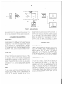
OPEN LOOP SYSTEM
Figure 4. 1 shows a system for obtaining a recorder plot of
count rate vs energy, using the 487 for sweeping the
window of the single-channel analyzer through the
spectrum derived from the detector. This system is
"open loop" in the sense that, for an energy scan,
operation of the 487 is not controlled by the results
of the data being collected. That is, there is no feedback
to alter the operation of the 48'7 as the scan progresses.
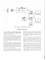
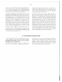
CLOSED LOOP SYSTEM
Figure 4.2 shows a system for obtaining a histogram plot
of count rate vs energy, using the 487 for stepping the
window of the single-channel analyzer through the spectrum derived from the detector. ln this digital data
acquisition system, data are collected for a preset time
(selected by the ORTEC 434 Digital Rate Meter) at one
energy. At the end of the preset time interval a BUSY
siqnal is generated from the printout control unit, the
rate meter is automatically reset for a new data-taking
interval, and the 487 output is moved to the next level.
The data taken at each energy setting may be printed
out on computer-compatible punched paper tape with
the Teletype 33-ASR.
5
r:
48ó
Âmplifier Pulse l{eight Analyrer
c
o
o
o
c¡
Analyzer
to9Pc
Amplifier
Output
SCA
I
npu
I
I
L
Ext
tL
J
t
0igital
E
Ratemeter
Strip Chart Recorder
Neg
Output
Spectrum
S
cannel
0r
clF|TEC
432
447
Printout
Advance
Control
Busy
L
20u76
¡
Y
X
I
t-
E
X-Y Plotter
ASR.33
TEI.ETYPE
Fi9.4.2. Closed Loop System Digital Data Acquisition.
5" CIRCUIT DESCRIPTION
The 487 is basically a programmable voltage
staircase
voltage (START LEVEL) through a number
of
generator. The staircase output is obtained by sequencing
a d¡g¡tal-to-analog converter f rom a selected starting
steps
selected by the CHANNELS control.
lC1 through lC1 1 comprises an eleven-bit binary counter.
The outputs of the successive binary stages of this
counter are fed into eleven gates comprised of O1
through O33. 01 , 02, and 03 make up the basic gate
which is duplicated for the successive stages. The output
of the gate Uunction of emitters of 02 and 03) is
either at ground potential or at a positive l2-V level,
depending upon the state of the driving flip-flop in the
binary counter.
The outputs of the gates go to a res¡st¡ve ladder network
which sums the weight of the successive stages of the
counter in binary fashion. This sum is fed into the input
of the operational amplifier 1C12. The output of lC12 is a
voltage which reflects the state
of the counter with
a
resolution of 1 out of 1O24 steps. The eleven-bit counter
is automatically reset to zero state after the 1 024th step by
the network comprised of O39 and O40.
R86 is a single-turn potentiometer (SPAN) in the feedback loop of lC12 and thus determines the closed loop
gain of that stage. lCl 3A takes the output voltage of lC12
and amplifies it to a 10-V level for a START LEVEL
setting (R89)
of 10 V or full scale. This output (NEG
of 442. O42 is an
OUTPUT) is present at the em¡tter
emitter follower that prov¡des the current-handling capability of driving the external 'raseline lnputs of up to 10
ORTEC single-channel analyzers lC138 and O43 invert
the negative output voltage to provide a positive output
voltage at CN-4.
The binary counter may be driven in several different
ways. ln the FULL SWEEP mode of operation it is
driven by the uniiunction oscillator o35. O34 acts as a
constant current source for charging the capacitor C13.
The oscillation freqüency is determined by C13, the
magnitude of its charging current, and the trigger voltage
at the emitter of O35. O44 serves as a current sump to
stop the oscillator whenever a STOP lras been made.
lC18A and lC18B form a fl ip-flop which el iminates switch
bounce from the START push button switch. lC16A and
lC168 form an R-S fl ip-flop for the start-reset function.
Suppose that in the FULL SWEEP mode, a start input is
obtained, either from the front-panel START push button
or the rear-panel ADVANCE input. A negative trans¡tion
at pin 7 of lC19A rvill occur which will be inverted by
lC198. This positive signal at pin 6 of lC198 will set the
starl-reset flip-flop lC16A and lC.l 68. The resulting
negative transition at pin 6 of lC'l 6B will allow the
oscillator pulser to pASS through the gate, lC158, which
was closed up to now. Thus a train of pulses will appear
b
at point F, which is the input of the least significant bit
of the binary counter. The purpose of grounding points
G, H, J, and K successively with the CHANNELS switch
is to inhib¡t the contribution of the corresponding least
significant bits to the output staircase waveform.
ln the STEP ADVANCE mode, suppose rhat rhe START
push button is depressed. This action willset-pin 7 of the
start-stcp fl ip-flop consisting of lC14A and lC14B low.
6 of lC168 will be set low. Thus
input pulses present at the ADVANCE input will pass
through the gate, lC'1 54, and appear on one of the points
A, B, C, D, or E, according to the setting of the
CHAN NE LS switch. Suppose, for example, that the
CHANNELS control is set at 64. Then the clock pulses
will be present at point C and thus be fed into the fifth
binary stage of the binary counter. The first four stages or
the four least significant bits will not contribute to the
output staircase voltage; therefore the output will step
1 0)L
through its range in
or 64 equal steps and then
Simultaneously, pin
f
automatically reset. Once the start-reset flip-flop has been
set with a START, then all subsequent depressions of the
START push button will cause the output staircase voltage
lC17B and 041 comprise a.-one-shot multivibrator for
reshaping the RESET input pulse into a pulse sufficiently
long to assure the resetting of all the associated logic
circuitry. The front-panel R ESET push button is essentially
connected in parallel with this input.
The GATE output circuitry (O37, O38, and O45) is
driven from the output of the start-reset flip-flop consisting of lCl6A and lC168. When a start has been made
and pin 6 of lC16B goes low, O38 becomes saturated
and O45 is turned off. When the start-reset flip-flop has
been given a reset input, then O38 turns off and O45 becomes saturated due to pin 6 of lC168 going high.
This means that while The 487 is scanning, should the
GATE output be connected to the GATE input of an
ORTEC scaler or timer, then that scaler or timer will be
allowed to count (due to its GATE input going high).
Resetting fhe 487 pulls this gate low and inhibits further
counting in the scaler or timer. Should the GATE output
of the 487 be connected lo the chart advance input of
a strip-chart recorder whose input circuitry consists cf a
load to some negative supply voltage, then the GATE
output would supply up to 50 mA of current to enable
the chart to advance while the 487 is sweeping.
to move one step via the gate lC17A.
6. MAINTENANCE
The only maintenance that the 487 should require is
rout¡ne cal ibration of the 4014 Power Supply voltages.
Ail
SU
!12 and !24 should be
vol
r proper
ue.
For calibration adjustments internal to the 487, refer to
Section 4.2 of this manual, "Calibration Adjustments."
INSTRUCTIONS
The 487 may at any time be returned to ORTEC for
repair service at nominal cost. Our standard procedure
requires that each repaired instrument receive the same
extensive quality control tests that a new instrument
receives. Before returning the instrument, contact
Customer Service at ORTEC (615], 482-441 1 for information concerning shipment of the instrument.
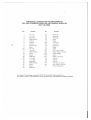
BIN/MODULE CONNECTOR PI N ASSIGNMENTS
FOR AEC STANDARD NUCLEAR INSTRUMENT MODULES
PER TID-20893
Pin
1
2
J
4
5
o
7
o
o
I
*l0
*1
1
12
13
14
15
*16
*1J
18
19
20
21
22
Pins marked
Pins marked
Function
*3
zó
-3
24
25
volts
volts
Spare Bus
Reserved Bus
Coaxial
Coaxial
Coaxial
200 volts dc
Spare
*6
volts
--6 volts
Reserved Bus
Spare
Spare
Reserved
*12 volts
-1 2 volts
Spare Bus
Reserved Bus
Spare
Spare
Reserved
26
21
*28
*29
30
31
JZ
JJ
*oA
J1
**35
""36
** 37
38
?o
40
*41
*42
tr
(*) are installed and wired in ORTEC 4014 and
(')
Function
Pin
eserved
Reserved
Reserved
Spare
Spare
R
*24 volts
-24
volts
Spare Bus
Spare
Spare
1 1 5 volts ac (Hot)
Power Return Ground
Reset (Scaler]
Gate
Reset (Auxiliarv)
Coaxial
Coaxial
Coaxial
1 15 volts ac (Neut.)
High Ouality Ground
Ground Guide Pin
401 B Modular System Bins.
and (**)are installed and wired in EG&G/ORTEC-HEP M250/N and M350/N NIMBINS.
l.6t<
Ptzg
6WEEP
P3
t2
4
ec
Q2
o+
-21
56
sÞP
ztzþ
2,2(
(E P)
-4
cñr
I
ÁÞVANCE
K
Ril9
i"*., c" - -l
f
s3
22t
+tz
31EP
H
AC'vANCE
cil5
SAME ,{s14"
p,6 lxPtJ Rlè
4
L
.trcl
B
- tl
L
I
RIì fHRtJ
3 l-
t4
c
¡c6
o
t0K
- tl
L
Íeþ
E
L
t-
Tc7
I
P.4
I
R54 fHcL, R57 _l
t-
q4
I
4
I,Ct¡
T
o
.t%
,tl"
c3
2oOpF
F?9
I
o(
qo
w)
3R
+24V
J
+t2v
l*1¿
á.rk
6PAÑ
æl
Rrot
cto
r.5k
Pt<'t
RtO2
6.lt<
O+
(R.P)
UNIE'5 OTH€PN,\'E NOIEO:
I. ALL Nø{,5 AR€ 2N7J'.3.
2 All PNPS APE 2r\B63AA
3 A¿L lræ âPe lN1oo9.
4 ALL PÉt5Æ MAptéDE J Ape N1pß,[âN.
5, A¿L ÆÉts7aÆ
.æE tN or¿t¿s.
G,.ALLA444¿Tæ APE tN qî,
7. IcS t4t5.,t6J7,l6,t9 ,æE
.to/.
lz.3
5K
.
4Le,4-
+êN
t.to
P67
rl¡ts onm$
]ffi-'m6
lflruS
Clr/
z
R66
R9ô
llo
Pag
5TA?1
LEVEL
lK) lT
(F P)
)
lo
toK
I
L-
(P,P,
Rto+
l,zK
-4
ro
6.8
qÊ
.t"h
t_
FC
t.sz
2¿S
pos
oulP(Jr
lOñV
c6
I
IK
2æ pF
P!l€
ß95
4F
toEa
c
{
351É
Re9
P%
P4
I
¿ñ.¿l
cp3
+t2
cb
.lolo
1tlctJ Qgo
âAú¿ AÈ"8,'
?..ê'fHc,9 36.?
-21
oulPuT
(e.P)
c,9
to,<
L
r3l<
+3-GV
¿R.P)
1-tJ¿
NEG
o-tôvo¿
4 L9t1
¿N3
RESEI
Rt09
,ot
+2
R92
@l
TQIZ
25.3
6K
Rá6
L
I
1
átK
+4
Pè1
3É.
Rrcr8
t16
cñ5
.ft"
q2SfAP(J Q27
PIo
ctz
+2
. lolo
ol
_l
42
+
R97
rOx
P5.2
éAÁE,. AS"E'
te@
+?1
5É
-'l
'ArÁe
Tr¡R¡J R5l
P4ê
+t2
z
D9
L6k
Pll
P4¿-
I
L
llK
.,%
_t
G.P.I
1Pt
J
Qlg TrlRU C2l
SrAÊr
Drl
Q40
D
P:î3
P,r3A
AS"B'
Q22 f*gtJ q24
I
lk
tóK
s5
PE5E7
6rñ6LE
c.<cLe
oo
P14
Rì2
tot<a
t6K
TllRr., P39
t-
r
Pil3
5tÐ
4
P-r5
4п
O16
c42Tr{R!' Pltá
L
P29
-l
AS"B"
H
+t2
211
+tz
teo
s,{lti.E. As"E'
It
fcê
19Btè
-l
L
I
É
s-7
3AME AS''6"
Tt{Pu P33
P36
P1
I
_-J
13 THQU Qr5
3{r/le
Í
-*
P)
P.22
Þr5
--1
R.3()
Ql6 lHPu
R9
ilK
G
þK+
_l
EI2O
Prlg
C^¡ ø
6ATE
(R.
6ÀvtÉ- tÉ"8"
Pz+-ft{EO lZ2'l
L
tl
D
I
I
c- *-""Gã
13X.
Þt9
I
I
o-r lHRu Q9
sAMr 4s h¡'
*x
B
A
CllAr.l,\¡Els
Q'?
(R,P)
I
¿
st
tilÛ
D16
-4V
1
<
[-----...------*
re
D
J28
F
ezí
ôK
P5
22X
4
e.
t6
Ptzt-t
C¡l,¿
STDP
3K
I
act
6^tD
E|S
e.9(.
(BP)
tlF
-2+
{2V
2*
A
+1*
PO$¡ER INÞt'T
?tt^A(.
2t2r.
to{¡
-4V
I
F
+3C
ct3-
-lz
+t2
lo
Rl3l *
à66t<
+zav
Irt
+2
gz
DI
t--
q,"q
o1
Rr!2
+8,6v
+r2V
5ro
ct4
6.a4F
f,C. rcweR
APF'.Y
sætft@
a
trITEC
ïlå.'Ål; lJ- IOO MIOLANO FOAD, OAK HIOGE, TENNESSEE 378SC
MoDEL
487
sæc7?p¡v' g4NNæ
J t2-at-¿.çl t1 n27Æ
I
ù
n
?l
EEìaEi ORTEC
76 Offices in 49 Countries.
For more iñformation on EG&G ORTEC products or their
applications, contact your local EG&G ORTEC Representative
or:
United States:
EG&G ORTEC lncorporated, 100 Midland Rd., Oak Ridge, TN
37830, telephone (615) 482-4411, Telex 55-7450
W. Germany:
EG&G ORTEC GmbH, Munich, telephone (089) 98-71-73
United Kingdom:
EG&G ORTEC Limited, Bracknell, telephone 55455
France:
EG&G ORTEC S.A.R.L., Rungis-Cedex, telephone 687 -25-71
Italy:
EG&G ORTEC SpA, Milan, telephone 738-6294
Brazil:
EG&G ORTEC Limitada, São Paulo, S.P., telephone 275-3943