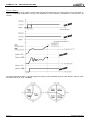
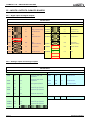
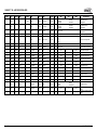
1
User manual CLIMATIC™ 60 Aircooled chillers MUL41E-0610/06-2011 CLIMATIC™ 60 – AIRCOOLED CHILLERS TABLE OF CONTENTS 1. INTRODUCTION ........................................................................................................................ 2 2. OVERVIEW ................................................................................................................................. 2 3. SCHEDULING ZONE ................................................................................................................. 3 4. SCHEDULING MODE ................................................................................................................ 4 5. SCHEDULING ZONE ANTICIPATION ...................................................................................... 5 6. CHANGEOVER HEAT / COOL .................................................................................................. 6 7. FREE INPUT / OUTPUT ............................................................................................................. 8 8. WATER EVAPORATOR .......................................................................................................... 12 9. PUMP EVAPORATOR MANAGMENENT ............................................................................... 16 10. PUMP EVAPORATOR FLOW CONTROL............................................................................... 17 11. PUMP CONDENSER MANAGMENENT .................................................................................. 19 12. PUMP CONDENSER FLOW CONTROL ................................................................................. 20 13. COMPRESSOR ........................................................................................................................ 23 14. CONDENSER FAN ................................................................................................................... 25 15. FAN SMART ACCOUSTIC SYSTEMTM ................................................................................. 27 16. COIL DEFROST ....................................................................................................................... 30 17. WATER CONDENSER ............................................................................................................. 31 18. FREECOOLING ........................................................................................................................ 32 19. ELECTRICAL HEATER ........................................................................................................... 33 20. POWER FACTOR CORRECTOR ............................................................................................ 34 21. MASTER / SLAVE .................................................................................................................... 35 22. DISPLAY DC60 ........................................................................................................................ 36 23. DISPLAY DS60 ........................................................................................................................ 38 24. BMS .......................................................................................................................................... 42 25. INPUTS / OUTPUTS CLIMATIC BOARDS .............................................................................. 44 26. SETTING LIST .......................................................................................................................... 46 27. ALARMS ................................................................................................................................... 69 MUL41E-0610/06-2011 Page 1 CLIMATIC™ 60 – AIRCOOLED CHILLERS 1 - INTRODUCTION 1.1 - CONTROLLER CLIMATIC™60 The new generation of microprocessor based control, CLIMATIC™ 60 may be fitted to the Lennox Chiller or Heat pump range. It inherits 20 years of technology and field operating experience from its predecessors the CLIMATICTM1 and CLIMATICTM2 and CLIMATICTM50. LENNOX has found the latest hardware technology available on the market place and developed software specifically designed for Chiller and Heat pump applications, maximising the LENNOX unit’s efficiency and performance. 1.2 - COMPATIBILITY This documentation is compatible with the programs Chiller and Heat pump: • ECOLEAN range from software version CH060 STD - Vers. 01.0 - Rev 00.0, • NEOSYS standards range (STD) from software version CH060 STD - Vers. 01.0 - Rev 00.0. 1.3 - WARNING Any parameter modification should be carried out by trained and licensed competent technician. Before start-up or restart of a unit controlled by the CLIMATIC™ 60, it is mandatory to check adequacy between CLIMATIC™ 60 and the unit with its options. In case of wrong parameters, the inputs / outputs connections could be incorrect and may create some operation problems for the units and ultimately breakdowns. Lennox cannot be held responsible for any claims on the units due to a wrong parameters sequence or a parameters modification carried out by non competent technicians. In this case, the warranty will be legally null and void. 2 - OVERVIEW Page 2 MUL41E-0610/06-2011 CLIMATIC™ 60 – AIRCOOLED CHILLERS 3 - SCHEDULING ZONE 3.1 - Function The CLIMATIC™ 60 is provided by a real time clock which offers solutions to specify a weekly schedule. 3.2 - Description The CLIMATIC™ 60 schedule manages up to 7 distinct clock zones per day from 00h00 to 24h00 and from Monday to Sunday. The zone can start at different time for each day of the week in order to optimise the operating of the unit. 3.3 - Settings The different settings to adjust the scheduling zone are available in the menu: • (2141): Start time of the zone 0 from Monday to Sunday. • (2142): Start time of the zone 1 from Monday to Sunday. • (2143): Start time of the zone 2 from Monday to Sunday. • (2144): Start time of the zone 3 from Monday to Sunday. • (2145): Start time of the zone 4 from Monday to Sunday. • (2145): Start time of the zone 5 from Monday to Sunday. • (2146): Start time of the zone 6 from Monday to Sunday. Note: The start time can take different values from Monday to Sunday. The start time of the zone 0 must be set to 00h00. MUL41E-0610/06-2011 Page 3 CLIMATIC™ 60 – AIRCOOLED CHILLERS 4 - SCHEDULING MODE 4.1 - Function The CLIMATIC™ 60 is able to control different mode for each zone in order to optimise the operating of the unit. 4.2 - Description The CLIMATIC™ 60 can manage up to 4 different modes. 4.3 - Settings The different settings to adjust the scheduling mode are available in the menu: • (2151): Mode used during the period of the zone 0 from Monday to Sunday. • (2152): Mode used during the period of the zone 1 from Monday to Sunday. • (2153): Mode used during the period of the zone 2 from Monday to Sunday. • (2154): Mode used during the period of the zone 3 from Monday to Sunday. • (2155): Mode used during the period of the zone 4 from Monday to Sunday. • (2156): Mode used during the period of the zone 5 from Monday to Sunday. • (2157): Mode used during the period of the zone 6 from Monday to Sunday. Note: The mode used can take different values from Monday to Sunday. Page 4 MUL41E-0610/06-2011 CLIMATIC™ 60 – AIRCOOLED CHILLERS 5 - SCHEDULING ZONE ANTICIPATION 5.1 - Function The CLIMATIC™ 60 allows the start up of the unit before the pre-specifyd hour of the first zone (Zone 1) of the day. 5.2 - Description This function is able to start the unit in zone 1 earlier if the outdoor temperature is under a specify threshold. The typical application is to start the unit in heating mode if the weather is too cold compare to the actual season. Example : • (2142): Start time zone 1 : 8h00, • (2161): Anticipation foot : 10.0°C, • (2162): Anticipation gradient: 10mm/°C. In this example the foot is set to the value 10.0°C, which means the zone 1 will always start at 8h00 if the outside air temperature is higher than 10.0°C. If the outside air temperature is less than 10.0°C the zone 1 will start according to the gradient selected and the difference from the foot value and the actual outside air temperature (10.0 - 7.0 = 3.0 x 10 = 30min). So the new start time for the zone 1 is 7h30. 5.3 - Settings The different settings to adjust the anticipation are available in the menu: • (2161): Anticipation foot. • (2162): Anticipation gradient. MUL41E-0610/06-2011 Page 5 CLIMATIC™ 60 – AIRCOOLED CHILLERS 6 - CHANGEOVER HEAT / COOL 6.1 - Function The CLIMATIC™ 60 control the changeover mode (for reversible units only) to specify the appropriate demand on heat water or chilled water production. 6.2 - Description The changeover can also be pre-specify according to the scheduling and can take different mode for each schedule mode (A, B, C, D, and BMS). The changeover mode can be set by different solutions: Automatically: The CLIMATIC™ 60 determines the appropriate production of the water according to the outside temperature and move automatically the unit from the cooling to heating mode and heating to cooling mode. If the outside temperature is below the setting value (3225), the unit will operate as a heat pump. If the outside temperature is over the setting value (3226), the unit will operate as a chiller. Manually: The changeover mode is pre-specifyd for each schedule mode. The various modes available are “Cool” mode, “Heat” mode or “Dead zone”. In this case the outside temperature has not effect on the changeover mode. Remotely: The changeover mode is set according to a remote dry contact connect on a free custom digital input. In this case the unit swaps in cooling or heating mode according to the status of the digital input. Please refer to the paragraph “Free Input / Output” for more details. Page 6 MUL41E-0610/06-2011 CLIMATIC™ 60 – AIRCOOLED CHILLERS Terminal DC60: The changeover mode (cool / heat) can be modified by the terminal DC60 by pressing the “mode” button. Heat Cool Auto Dead zone When the “Auto” mode is selected, the icon “Cool” or “Heat” is displayed to signal the actual operating mode. Due to the communication delay, after pressing the “mode” button it is well advised to wait few seconds, the time to refresh of the icon on the display. 6.3 - Settings The different settings to adjust the changeover mode are available in the menu: • (3224): Changeover mode (Cool, Heat, Auto, Dead zone) for each schedule mode (A, B, C, D, and BMS). • (3225): Minimum of outside temperature to swap to heating mode. If (3224)=“Auto”. • (3226): Maximum of outside temperature to swap to cooling mode. If (3224)=“Auto”. MUL41E-0610/06-2011 Page 7 CLIMATIC™ 60 – AIRCOOLED CHILLERS 7 - FREE INPUT / OUTPUT 7.1 - Function The CLIMATIC™ 60 have free input / output on the main board BM60 and the expansion board BE60 to offer some possibilities to customize input / output for remote control of the unit. 7.2 - Description The number of the free customized input / output is: • 2 free contact input (normally opened) on BM60, • 1 free contact output (normally opened) on BM60, • 4 free contact input (normally opened) on BE60, • 4 free contact (normally opened) output on BE60, • 4 free analog input on BE60. The expansion board BE60 is an additional board fixed on DIN rail. The description of the various connectors is: 1) Power supply of the board, 2) Analog output 0/10V : Not used, 3) Network bus to the CLIMATIC™ 60 BM60, 4) 4 Digital inputs : Only dry contacts, 5) Status LED of the network bus, 6) Serial address dip-switch of the network bus, 7) 4 Analog inputs configurable by pair B1-B2 and B3-B4, 8) 4 Digital outputs: Only dry contacts. Power supply The expansion board BE60 is power in 24Vac, +/-15%, 50-60Hz, Pmax=6W. Page 8 MUL41E-0610/06-2011 CLIMATIC™ 60 – AIRCOOLED CHILLERS Analog input The 4 analog inputs can be used as NTC probe (-50T90 °C; R/T 10 KΩ at 25 °C) or 4/20mA (Impedance = 100Ω) current signal. They are configurable by pair B1-B2 and B3-B4. The configuration of the type of the input is automatically set by the CLIMATIC™ 60. The analog input can be configurable to be used as one of these items: 0) Not set, 1) Water set point desired, 2) Offset set point desired, 3) Free NTC probe. Digital input The 4 digital inputs must be used with dry contacts according to the following example. The digital input can be configurable to be used as one of these items: 0) Not set, 1) Remote On/Off, 2) Remote reset alarm, 3) Swap to second water set point, 4) Force the cooling mode, 5) Force the heating mode, 6) Force the dead zone mode, 7) Force the defrost delay (10min), 8) Disable the circuit 1 (All compressors), 8) Disable the circuit 2 (All compressors), 9) Disable the circuit 1-compressor 1, 10) Disable the circuit 1-compressor 2, 11) Disable the circuit 1-compressor 3, 12) Disable the circuit 2-compressor 1, 13) Disable the circuit 2-compressor 2, 14) Disable the circuit 2-compressor 3, 15) Force the mode A, 16) Force the mode B, 17) Force the mode C, 18) Force the mode D, 19) Force the mode BMS, 20) Status of electrical heaters, 21) Free digital input. MUL41E-0610/06-2011 Page 9 CLIMATIC™ 60 – AIRCOOLED CHILLERS Digital output The 4 digital outputs are dry contacts and the maximum commutable power is 2000VA, 250Vac. The digital output can be configurable to be used as one of these items: 0) Not set, 1) General alarm (alarm minor), 2) General fault (alarm major), 3) General alarm on circuit 1, 4) General alarm on circuit 2, 5) General alarm on condenser, 6) General alarm on evaporator pump(s), 7) Flow evaporator alarm, 8) Unit enable, 9) Unit available (ready to start), 10) Unit running (one compressor ON), 11) Unit running 100% (all compressor(s) ON), 12) Unit operating in cooling mode, 13) Unit operating in heating mode, 14) Unit operating in dead zone mode, 15) Unit operating in zone 0 16) Unit operating in zone 1, 17) Unit operating in zone 2, 18) Unit operating in zone 3, 19) Unit operating in zone 4, 20) Unit operating in zone 5, 21) Unit operating in zone 6, 22) Unit operating in mode A, 23) Unit operating in mode B, 24) Unit operating in mode B, 25) Unit operating in mode D, 26) Unit operating in mode BMS, 27) Output for additional electrical heater 1, 28) Output for additional electrical heater 2, 29) Output for additional electrical heater 3, 30) Output for additional electrical heater 4, 31) Free digital output. Page 10 MUL41E-0610/06-2011 CLIMATIC™ 60 – AIRCOOLED CHILLERS 7.3 - Settings The different settings to configure the custom I/O are available in the menu: • (3131): Setting for the digital output on the connector BM60-J14-NO7, • (3132): Setting for the digital output on the connector BE60-J5-NO1, • (3133): Setting for the digital output on the connector BE60-J6-NO2, • (3134): Setting for the digital output on the connector BE60-J7-NO3, • (3135): Setting for the digital output on the connector BE60-J8-NO4. • • (3141): Setting for the digital input on the connector BM60-J4-ID4, • (3142): Setting for the digital input on the connector BM60-J4-ID7, • (3143): Setting for the digital input on the connector BE60-J4-ID1, • (3144): Setting for the digital input on the connector BE60-J4-ID2, • (3145): Setting for the digital input on the connector BE60-J4-ID3, • (3146): Setting for the digital input on the connector BE60-J4-ID4. • • (3151): Setting for the analog input on the connector BE60-J9-B1, • (3152): Setting for the analog input on the connector BE60-J9-B2, • (3153): Setting for the analog input on the connector BE60-J10-B3, • (3154): Setting for the analog input on the connector BE60-J10-B4. MUL41E-0610/06-2011 Page 11 CLIMATIC™ 60 – AIRCOOLED CHILLERS 8 - WATER EVAPORATOR 8.1 - Function The CLIMATIC™ 60 controls the chilled or heat temperature according to the specifyd set point. The desired set point can be set by different solutions: 8.2 - Description The CLIMATIC™ 60 offers various possibilities to specify the water evaporator set point. 8.2.1 - Dynamic value The CLIMATIC™ 60 determines the appropriate water set point according to the outside temperature in order to optimise the energy consumption. This method requires pre-defining 2 different water set points corresponding to 2 outside temperatures. 8.2.2 - Fix value In this case the outside temperature has no effect on the water set point and the set point (3238) and (3239) must be set at the same value. 8.2.3 - External current 4/20mA signal In this case the actual set point is calculated according to the analog input current. The set point (3238) and (3239) specifyd the corresponding set point for 4mA and for 20mA. Page 12 MUL41E-0610/06-2011 CLIMATIC™ 60 – AIRCOOLED CHILLERS 8.2.4 - External second set point In this case the actual set point is specifyd by one of the 2 set point (3238) and (3239). The final set point depends on the status of the digital dry contact allocated to this function. 8.2.5 - External current 4/20mA offset In this case the set point is set by one of the previous solution and can be adjust with an offset of +/- 1.0°C. 8.2.6 - C60 value The CLIMATIC™ 60 receives the water set point from the DC60. If the set point read is different from the one calculated by the CLIMATIC™ 60, the new set point is set by the DC60 during the actual zone. Each time the zone is changing, the DC60 set point is overwritten by the CLIMATIC™ 60 set point. 8.2.7 - BMS value The CLIMATIC™ 60 receives the water set point from the BMS. Refers to the “BMS” paragraph for more details. The cooling and heating set points can be pre-specified according to the scheduling and can take different mode for each schedule mode (A, B, C, D, and BMS). MUL41E-0610/06-2011 Page 13 CLIMATIC™ 60 – AIRCOOLED CHILLERS 8.3 - Settings The different settings to adjust the water evaporator set points are available in the menu: 8.3.1 - COOLING MODE • (3236): Minimum of outside air temperature corresponding to the water evaporator set point (3238) (used only for dynamic set point), • (3237): Maximum of outside air temperature corresponding to the water evaporator set point (3239) (used only for dynamic set point), • (3238): o Dynamic set point: Water evaporator temperature set point desired corresponding to outside air temperature (3236), o Fix set point: Water evaporator temperature set point desired. o External current 4/20mA signal: Water evaporator temperature set point corresponding to a current signal of 4mA. o External second set point: First water evaporator temperature set point corresponding to a dry contact opened. • (3239): o Dynamic set point: Water evaporator temperature set point desired corresponding to outside air temperature (3237), o Fix set point: Water evaporator temperature set point desired. o External current 4/20mA signal: Water evaporator temperature set point corresponding to a current signal of 20mA. o External second set point: Second water evaporator temperature set point corresponding to a dry contact closed. 8.3.2 6 HEATING MODE • (3246): Minimum of outside air temperature corresponding to the water evaporator set point (3248) (used only for dynamic set point), • (3247): Maximum of outside air temperature corresponding to the water evaporator set point (3249) (used only for dynamic set point), • (3248): o Dynamic set point: Water evaporator temperature set point desired corresponding to outside air temperature (3246), o Fix set point: Water evaporator temperature set point desired. o External current 4/20mA signal: Water evaporator temperature set point corresponding to a current signal of 4mA. o External first set point: First water evaporator temperature set point corresponding to a dry contact opened. • (3249): o Dynamic set point: Water evaporator temperature set point desired corresponding to outside air temperature (3247), o Fix set point: Water evaporator temperature set point desired. o External current 4/20mA signal: Water evaporator temperature set point corresponding to a current signal of 20mA. o External second set point: Second water evaporator temperature set point corresponding to a dry contact closed. Page 14 MUL41E-0610/06-2011 CLIMATIC™ 60 – AIRCOOLED CHILLERS 8.4 6 Control The Climactic™60 adjusts and hold the fluid outlet temperature as close as possible to the set point, by controlling the number of compressor stages depending on the thermal load of the system. The controller calculates constantly the required capacity to reach the temperature set point. This variable is called “CAPACITY FACTOR” (CF) and its value can vary from 0 to 100%. It is directly linked to the number of control stages of the unit. Thus for a unit with 4 stages of regulation, the CF will start and stop a stage with the following values: ~0-25-50-75-100%. It then evolves following the principles detailed in the diagram. + 2K CF INCREASES (Start more Capacity Stages) CF FROZEN + 1K Difference between the outlet water temperature and the 0 set point CF DECREASES (Removes Capacity Stages) - CF FROZEN - FAST SLOW Water Temperature Change rate SLOW FAST In order to anticipate, the reference point is recalculated each time the difference between air temperature and set point reach a minimum or a maximum. Moreover the inlet temperature is used to limit the capacity factor to prevent from too slow reactivity of outlet capacity factor of the unit. Example: • Unit EAC 2104: cooling capacity: 210KW with: • C1.Cp1 = 19.2%, • C1.Cp2 = 30.8%, • C2.Cp1 = 19.2%, • C2.Cp2 = 30.8%. • • Maximum delta T° (inlet - outlet) at full load: setting (3261) = 5.0°C. Outlet water evaporator temperature set point: setting (3238) = (3239) = 7.0°C. Stage Minimum Inlet temp. (°C) Maximum capacity factor (%) Expression 0 0 0 0 1 8.54 30.8 7.0 + 30.8*5.0/100 2 10.80 61.6 7.0 + 2*30.8*5.0/100 3 11.04 80.8 7.0 + (19.2+2*30.8)*5.0/100 4 12.00 100.0 7.0 + 2*(19.2+30.8)*5.0/100 MUL41E-0610/06-2011 Compressor ON circuit 1 Compressor ON circuit 2 Page 15 CLIMATIC™ 60 – AIRCOOLED CHILLERS 9 - PUMP EVAPORATOR MANAGEMENT 9.1 - Function The CLIMATIC™ 60 offers in option a solution to manage a single or double evaporator pump(s). 9.2 - Description In case of double pumps the CLIMATIC™ 60 can manage various possibilities of operating of the pumps. 9.2.1 - Priority to the pump 1 The CLIMATIC™ 60 specifies the priority to the pump 1 to start first. The pump 2 is used only as backup pump and will start only if the pump 1 is in alarm. The pump 1 is kept ON as soon as the machine is enabled. 9.2.2. - Priority auto to the pump 1 Same configuration as the case 1, except that the pump will be stopped in case of dead zone changeover (winter / summer). 9.2.3 - Priority to the pump 2 The CLIMATIC™ 60 specifies the priority to the pump 2 to start first. The pump 1 is used only as backup pump and will start only if the pump 2 is in alarm. The pump 2 is keep ON as soon as the machine is enabled. 9.2.4 - Priority auto to the pump 2 Same configuration as the case 3, except that the pump will be stopped in case of dead zone changeover (winter / summer). 9.2.5 - No Priority The CLIMATIC™ 60 specifies automatically the priority of the pump according the operating hour counter. The first pump to start will be the one which has the less number of hours of operation. In order to equalize the number of hours the unit is stopped every Tuesday at 02h00 am to re-specify the priority. 9.2.6 - No Priority auto Same configuration as the case 5, except that the pump will be stopped in case of dead zone changeover (winter / summer). 9.3 - Settings The different settings to adjust the pump mode are available in the menu: • (3371): Type of rotation of the pump(s), Page 16 MUL41E-0610/06-2011 CLIMATIC™ 60 – AIRCOOLED CHILLERS 10 - PUMP EVAPORATOR FLOW CONTROL 10.1 - Function The ClimaticTM60 offers the possibility to have a flow control in option. 10.2 - Description There is up to 4 modes to manage the evaporator water flow. 10.2.1 - Fix speed The CLIMATIC™ 60 maintains a fix flow according to the maximum speed desired. The flow is set to the minimum flow desired only when none compressor is running. 10.2.2 - Fix delta T° The CLIMATIC™ 60 maintains a fix delta of temperature according to the inlet and outlet temperature probe on the evaporator. The delta of temperature desired is customized in the menu (3374). MUL41E-0610/06-2011 Page 17 CLIMATIC™ 60 – AIRCOOLED CHILLERS 10.2.3 - Fix delta P The CLIMATIC™ 60 maintains a fix delta of pressure according to the transducers (in and out) on the pump. The delta of pressure desired is customized in the menu (3375). 10.2.4 - Fix Out P The CLIMATIC™ 60 maintains a fix out pressure according to the out transducer on the pump. The output pressure desired is customized in the menu (3376). 10.3 - Settings The different settings to adjust the flow control are available in the menu: • (3372): Type of flow control, • (3374): Delta of temperature desired on the evaporator water (Outlet - Inlet), • (3375): Delta of pressure desired on the water pump (Out - In), • (3376): Output pressure desired on the water pump (Out), • (3377): Minimum of flow on the evaporator water, • (3378): Maximum of flow on the evaporator water. Page 18 MUL41E-0610/06-2011 CLIMATIC™ 60 – AIRCOOLED CHILLERS 11 - PUMP CONDENSER MANAGMENENT 11.1 - Function The CLIMATIC™ 60 offers in option a solution to manage a single or double condenser pump(s). 11.2 - Description In case of double pumps the CLIMATIC™ 60 can manage various possibilities of operating of the pumps. 11.2.1 - Priority to the pump 1 The CLIMATIC™ 60 specifies the priority to the pump 1 to start first. The pump 2 is used only as backup pump and will start only if the pump 1 is in alarm. The pump 1 starts when the unit is enabled and will never be stopped. 11.2.2 - Priority auto to the pump 1 Same configuration as the case 1, except that the pump will be stopped in case of dead zone changeover (winter / summer). 11.2.3 - Priority to the pump 2 The CLIMATIC™ 60 specifies the priority to the pump 2 to start first. The pump 1 is used only as backup pump and will start only if the pump 2 is in alarm. The pump 2 starts when the unit is enabled and will never be stopped. 11.2.4 - Priority auto to the pump 2 Same configuration as the case 3, except that the pump will be stopped in case of dead zone changeover (winter / summer). 11.2.5 - No Priority The CLIMATIC™ 60 specifies automatically the priority of the pump according the operating hour counter. The first pump to start will be the one which has the less number of hours of operation. In order to equalize the number of hours the unit is stopped every Tuesday at 02h00 am to re-specify the priority. 11.2.6 - No Priority auto Same configuration as the case 5, except that the pump will be stopped in case of dead zone changeover (winter / summer). 11.3 - Settings The different settings to adjust the pump mode are available in the menu: • (3381): Type of rotation of the pump(s), MUL41E-0610/06-2011 Page 19 CLIMATIC™ 60 – AIRCOOLED CHILLERS 12 - PUMP CONDENSER FLOW CONTROL 12.1 - Function The CLIMATIC™ 60 offers the possibility to have a flow control in option. 12.2 - Description 12.2.1 - Fix flow The CLIMATIC™ 60 maintains a fix flow according to the maximum flow desired. The flow is set to the minimum flow desired only when none compressor is running. 12.2.2 - Fix delta T° The CLIMATIC™ 60 maintains a fix delta of temperature according to the inlet and outlet temperature probe on the condenser. The delta of temperature desired is customized in the menu (3384). Page 20 MUL41E-0610/06-2011 CLIMATIC™ 60 – AIRCOOLED CHILLERS 12.2.3 - Fix delta P The CLIMATIC™ 60 maintains a fix delta of pressure according to the transducers (in and out) on the pump. The delta of pressure desired is customized in the menu (3385). 12.2.4 - Fix Out P The CLIMATIC™ 60 maintains a fix out pressure according to the out transducer on the pmup. The output pressure desired is customized in the menu (3386). 12.2.5 - Fix condensing temperature The CLIMATIC™ 60 maintains a fix condensing temperature according to the outlet probe on the condenser. The condensing set point is customized in the menu (3546). MUL41E-0610/06-2011 Page 21 CLIMATIC™ 60 – AIRCOOLED CHILLERS 12.3 - Settings The different settings to adjust the flow control are available in the menu: • (3382): Type of flow control, • (3384): Delta of temperature desired on the evaporator water (Outlet - Inlet), • (3385): Delta of pressure desired on the water pump (Out - In), • (3386): Output pressure desired on the water pump (Out), • (3387): Minimum of flow on the condenser water, • (3388): Maximum of flow on the condenser water. Page 22 MUL41E-0610/06-2011 CLIMATIC™ 60 – AIRCOOLED CHILLERS 13 - COMPRESSOR 13.1 - Function The CLIMATIC™ 60 manages the compressor(s) according to the outlet temperature demand and engages the number of compressor calculated to reach the water set point. 13.2 - Description The CLIMATIC™ 60 offers possibilities to disable some compressor(s) on the circuit. Note this opportunity can be also done by dry contact (Refer to the “Free input/output” paragraph). Item Compressor on circuit (case of 3 compressors) 0 1 2 3 4 5 6 7 The compressors allowed to run can be pre-specifyd according to the scheduling and can take different values for each schedule mode (A, B, C, D, and BMS). Moreover, the priority to circuit can be specified (for units with 2 circuits) “Auto”: This is the CLIMATIC™ 60 which decide the priority of the circuit to start first. Note that the priority is swapped when all the compressors are stopped in order to optimise the operating hours of the two circuits. “Priority C1”: The priority is fixed to the circuit 1, which means this is the circuit 1 which starts first and stops the last. “Priority C2”: The priority is fixed to the circuit 2, which means this is the circuit 2 which starts first and stops the last. MUL41E-0610/06-2011 Page 23 CLIMATIC™ 60 – AIRCOOLED CHILLERS The compressor is subject to various operating time in order to prevent from damage operating. • The minimum ON time of the compressor is fixed to 1 minute, • The minimum OFF time of the compressor is fixed to 1 minute, • The minimum between 2 starts of the same compressor is fixed to 5 minutes. 13.3 - Settings The different settings to configure the compressors are available in the menu: • (3331): Enable of the compressor(s) on the circuit 1 • (3332): Enable of the compressor(s) on the circuit 2 • (3335): Priority of the circuit rotation. Page 24 MUL41E-0610/06-2011 CLIMATIC™ 60 – AIRCOOLED CHILLERS 14 - CONDENSER FAN 14.1 - Function The CLIMATIC™ 60 is used to maintain the high pressure as stable as possible in order to increase the performance of the unit. 14.2 - Description The CLIMATIC™ 60 has 2 different fan managements according to the type of unit: 14.2.1 - Ecolean unit (without fan speed inverter) The CLIMATIC™ 60 manages 2 speeds on the fan (low and high speed). 14.2.2 - Neosys unit (standard version) The condensing temperature is reached according to the set point selected in the menu (3546). The fans are managed by stages. /*******************/ UNDER CONSTRUCTION /*******************/ 14.2.3 - Neosys unit (premium version) The condensing temperature is reached according to the outside air temperature and tries to maintain a delta of 12°C. Note that in this case the setting in the menu (3546) has no effect except if the value selected is different from the factory value. In this case the condensing set point is the value selected in the menu (3546). A fan inverter controlled by a PID algorithm is used to adjust the speed variation of the fans. MUL41E-0610/06-2011 Page 25 CLIMATIC™ 60 – AIRCOOLED CHILLERS 14.3 - Settings The different settings to adjust the condensing control are available in the menu: • (3546): Condensing set point temperature. Page 26 MUL41E-0610/06-2011 CLIMATIC™ 60 – AIRCOOLED CHILLERS 15 - FAN SMART ACOUSTIC SYSTEM™ 15.1 - Function The CLIMATIC™ 60 controls the fan speed limit by the Smart Acoustic System™ which allows progressive adaptation of the unit to the building load while respecting the noise level constraints and the operating limits. 15.2 - Description The maximum sound level and the fan strategies can be adjusted according to the schedule mode in order to benefit from the different modes “High performance”, “Quiet” and “Quiet++” operation as well as in heating or cooling mode. The acoustic mode offers 2 possibilities to manage the condenser fan: 15.2.1 - “Quiet” In this mode, the fan capacity is limited according to the sound level desired. For fan using low / high speed, the high speed is locked. In case of condensing temperature too high, the CLIMATIC™ 60 unlocks the limit or the high speed to prevent from unloading compressor. MUL41E-0610/06-2011 Page 27 CLIMATIC™ 60 – AIRCOOLED CHILLERS 15.2.2 - “Quiet++” This mode is similar to the “Quiet” mode except that the fan speed limit or the high speed is never unlocked. In case of condensing temperature too high, the CLIMATIC™ 60 will unload a compressor to prevent from HP security. The Smart Acoustic System™ can be adjusted according to the scheduling and can take different value for each schedule mode (A, B, C, D, and BMS). Page 28 MUL41E-0610/06-2011 CLIMATIC™ 60 – AIRCOOLED CHILLERS 15.3 - Settings The different settings to adjust the acoustic mode are available in the menu: • (3544): Acoustic mode, • (3545): Maximum sound level noise (except for fan with low / high speed). MUL41E-0610/06-2011 Page 29 CLIMATIC™ 60 – AIRCOOLED CHILLERS 16 - COIL DEFROST 16.1 - Function The CLIMATIC™ 60 manages defrost procedure to avoid ice on the evaporator coil in heating pump mode (winter season). 16.2 - Description To avoid the icing of the external air exchanger during winter operating, it’s necessary to reverse the refrigerant cycle. There are 2 defrost mode: • Cyclic mode, • Dynamic mode (Not available in the software CH060 Vers.001). The defrost procedure is activated if the following conditions are met during 1 minute: • The outside air temperature is ≤ (3562), • One of the compressor(s) on the circuit has been running for a time ≥ (3564) since the last defrost, • The saturation temperature is ≤ (3563). The defrost procedure is characterised by the following steps: 1) Start electrical heater during 2 min (Only rooftop with electrical heater), 2) Stop the compressors on the concerning circuit, 3) Wait for 30s to equalise the pressure in the circuit, 4) Start all compressors on the circuit (if the outlet T° is not too low), 5) Reverse the reversing valve when ΔP>2 bars, 6) Start all condenser fans when the HP ≥ 55.0°C in order to dry the coil, 7) Stop all condenser fans when the HP ≤ 40.0°C, 8) Repeat the steps 4) to 5) 3 times, 9) Stop the compressors on the concerning circuit, 10) Wait for 1 min to equalise the pressure in the circuit, 11) End of procedure; restart the unit in heating mode. 12) Reverse the reversing valve when ΔP>2bar. : Note: • In case of alarm on the circuit during the defrost procedure, the defrosting is cancelled. • If the HP pressure doesn’t reach 55°C after 6 min, during the step 6), the defrost procedure is cancelled. • During the step 4) the compressor(s) could not start in order to not decrease too much the water temperature of the system. 16.3 - Settings The different settings to adjust the defrosting procedure are available in the menu: • (3561): Defrost mode (Cyclic, Dynamic), • (3562): Minimum of outside air temperature to enable defrost procedure, • (3563): Critical saturation temperature to enable defrost procedure • (3564): Minimum of interval time to enable defrost procedure. Page 30 MUL41E-0610/06-2011 CLIMATIC™ 60 – AIRCOOLED CHILLERS 17 - WATER CONDENSER /*******************/ UNDER CONSTRUCTION /*******************/ MUL41E-0610/06-2011 Page 31 CLIMATIC™ 60 – AIRCOOLED CHILLERS 18 - FREECOOLING 18.1 - Function The freecooling option ensures to reduce the electrical consumption using the outside air temperature to produce cool water. 18.2 - Description The freecooling uses water coil with helicoids fans control by the CLIMATIC™ 60. The freecooling has a higher priority face to the compressors. Once the freecooling capacity is over 95% for 2 min, the compressors can be engaged if necessary in order to reach the cooling set point. If the freecooling capacity decreases below 90%, the capacity factor of the compressor(s) capacity is locked to give the priority to the freecooling. The freecooling is enabled if the following conditions are met: • The unit is ready (On/Off, water flow, none alarm, etc..), • The freecooling fan driver is operating (none alarm) • Outside temperature < (Inlet temperature – 3°C). 18.3 - Settings The setting to configure the freecooling option is available in the menu: • (3164): Configuration of the freecooling option. Page 32 MUL41E-0610/06-2011 CLIMATIC™ 60 – AIRCOOLED CHILLERS 19 - ELECTRICAL HEATER 19.1 - Function The electrical heater option is an additional heating capacity to help the heat pump to reach the set point during hard winter period. 19.2 - Description The electrical heater option has both utilisations: 19.2.1 - Antifreeze heater In this case, the heater is used to prevent the evaporator water from antifreeze. The heater is activated when the low alarm temperature appears in cooling mode or when the safety low temperature is reached in heating mode. 19.2.2 - Auxiliary heater The heater is activated when the water temperature is far from the set point. In this case, the heater is used to help the compressors to reach the heating set point. 19.3 - Settings The setting to configure the electrical heater is available in the menu: • (3164): Configuration of the electrical heater. MUL41E-0610/06-2011 Page 33 CLIMATIC™ 60 – AIRCOOLED CHILLERS 20 - POWER FACTOR CORRECTOR 20.1 - Function The power factor correction is an additional capacitor bank to compensate the apparent power energy. 20.2 - Description The CLIMATIC™ 60 controls the status of the circuit breaker to inform (generate an alarm) in case of short circuit in the capacitor bank. 20.3 - Settings The setting to configure the power factor correction is available in the menu: • (3163): Configuration of the power factor correction. Page 34 MUL41E-0610/06-2011 CLIMATIC™ 60 – AIRCOOLED CHILLERS 21 - MASTER / SLAVE 21.1 - Function The CLIMATIC™ 60 offers possibilities to connect up to 8 units to allow relationship between each unit in order to perform the system. The pLAN bus is connected to Climatic™60 on the J8 connector of board BM60. A star connection is not recommended. For an optimum operation it is advised to connect a maximum of two cables per unit. The cable length should not exceed 500m and must use a 2 pairs with general shield like LiYCY-P (0.34 mm²). 21.2 - Description There are 2 different modes to manage the units (“Cascade” & “Backup”) 21.2 1 - The cascade mode: Used to engage additional cooling / heating capacity in order to reach the water set point. The cascade operating includes 2 modes: 1. Twin mode: the units work simultaneously in order to equalize the number of compressors stages to perform the capacity of the unit. The control manages only the increasing of capacity. The decreasing of stage(s) is controlled individually by each unit. As well the capacity power factor is controlled individually on each unit according to its demand. 2. Chain mode: the units start one after the other in serial sequence. In case of evaporator pump(s) in the unit, the pump(s) is engaged according to the demand of the system. 21.2.2 - The backup mode Used to help the system in case of alarm(s) on the unit running. The unit in standby will start only if one of the other unit(s) running is in alarm. In this case the unit in alarm will be stopped and replace by the one which was in standby. The CLIMATIC™ 60 manages also the rotation between the units declared. . In “Cascade” mode, that means that the first unit to start will change every week. In “Rol.Backup” mode, the unit in “Backup” is swapped every week. Example: In case of 4 units, the rotation is as follow: Week Week (n modulo 5) Week (n+1 modulo 5) Week (n+2 modulo 5) Week (n+3 modulo 5) Example Week 1 Week 2 Week 3 Week 4 Unit rotation ….U1 U2 U3 U4…. ….U4 U1 U2 U3…. ….U3 U4 U1 U2…. ….U2 U4 U3 U1…. The unit selected in standby is the one which has the higher critical(s) alarm(s). In case of disconnection of the slave(s) unit(s) (@pLAN = 28) from the master unit (@pLAN = 1) on the pLAN bus, the disconnected unit will operate alone. MUL41E-0610/06-2011 Page 35 CLIMATIC™ 60 – AIRCOOLED CHILLERS 22 - DISPLAY DC60 22.1 - Function The DC60 display is customized for the user to show a global operating overview of the unit and allow access to some settings. In case of remote display, the cable length should not exceed 30m. 22.2 - Description The DC60 terminal displays various status of the unit and offers the possibility to override the initial operating of the unit. Use the wheel button to display the data desired in the big area. The small area specifies the type of the data displayed. 22.2.1 - Set point “SET”: Specify the evaporator water set point calculated by the CLIMATIC™ 60. The set point can be modified directly by the DC60. Note that the select value will be automatically overwritten by the CLIMATIC™ 60 when the actual zone will change (Z0Z6) if a scheduling has been defined. 22.2.2 - Outlet temperature “OUT”: Specify the evaporator water outlet temperature. 22.2.3 - Inlet temperature “IN” Specify the evaporator water inlet temperature. 22.2.4 - Outside temperature “Air” Specify the outside air temperature. 22.2.5 - Alarm code “AL-” Specify the alarm(s) code(s) active. 22.2.6 - Alarm clear “CL-” Specify the alarm reset set point. To reset the active alarms, press the wheel button and set to 1 to active the reset. The setting is automatically cleared by the CLIMATIC™ 60. 22.2.7 - Low pressure “LP-1” Specify the low pressure of the circuit 1. 22.2.8 - High pressure “HP-1” Specify the high pressure of the circuit 1. 22.2.9 - Superheating “SH-1” Specify the superheating temperature of the circuit 1. 22.2.10 - Low pressure “LP-2” Specify the low pressure of the circuit 2. 22.2.11 - High pressure “HP-2” Specify the high pressure of the circuit 2. 22.2.12 - Superheating “SH-2” Specify the superheating temperature of the circuit 2. Page 36 MUL41E-0610/06-2011 CLIMATIC™ 60 – AIRCOOLED CHILLERS 22.2.13 - Schedule zone specify the schedule operating zone. Mode A, Mode B, Mode C, Mode D, Mode GTC. The terminal DC60 also displays the status of the main component of the unit in the status area. The icons can take different appearance according to the status of the component. Pump OFF (icon hidden), Pump ON (icon visible), Pump alarm (icon blinking). 22.3 - Settings The CLIMATIC™ 60 offers possibilities of override operations. 22.3.1 - On/Off When the “power” button is pressed during few seconds, the unit is ordered to start or stop. When the unit is “OFF”, the clock is displayed. 22.3.2 - Changeover mode The changeover mode (cool / heat) can be modified by the terminal DC60 by pressing the “mode” button. Heat Cool Auto When the “Auto” mode is selected, the icon “Cool” or “Heat” is displayed to signal the actual operating mode of the unit. Due to the communication delay, after pressing the “mode” button, it is well advised to wait few seconds, the time to refresh of th icon on the display. 22.3.3 - Clock: There is two way to modify the clock hour: a. Press the “clock” button during few seconds. When the hour blinking turn the wheel button to select the desired hour and validate by pressing the wheel button. Once the hour validate, repeat the procedure for the minute and the weekday. b. Press the “On/off” and “Fan” buttons simultaneously during few seconds. When the terminal displays “CODE” select the password “22” and validate by pressing the wheel button. Then select the item to modify (“year” Year, “mont Month, “nday” day of the month, “uday” weekday, “hour” Hour, “minS”Minute. MUL41E-0610/06-2011 Page 37 CLIMATIC™ 60 – AIRCOOLED CHILLERS 23 - DISPLAY DS60 23.1 - Function The DS60 terminal is a plug and play display, designed for maintenance and service people who want to access to advanced functionalities. 23.2 - Description The terminal address must be assign to establish the communication with the CLIMATIC™ 60. The procedure to configure the DS60 is: 1) Press the buttons “↓”, “↑”, “←” keys at same time during 5 seconds, 2) Use the “←” key to move the cursor on the address number, 3) Use the “↓”, “↑” keys to select the value “31” for the DS60 (“32” for the DS50) and confirm with the “←” key (The cursor go directly to the next data). 4) If the address has been modified, the next screen is displayed. In this case restart to the step 1). 5) Use the “↓”, “↑” keys to select the desired address of the CLIMATIC™ 60. The CLIMATIC™ 60 address must be at the address “1” except if there is several units linked. The next screen is displayed. 6) Press the “←” key to go to the next step. Page 38 MUL41E-0610/06-2011 CLIMATIC™ 60 – AIRCOOLED CHILLERS 7) The following screen describe the type of connection used. Set the display as a Private “Pr” terminal. The other terminals (Trm2 and Trm3) are not used. So their addresses must be adjusted to “None”. Finally confirm the modifications and swapping the text “No” to “Yes” and validate with the“←” key. The first screen after a start up contains the main information about the CLIMATIC™ 60‘s software. The DS60 is organised in 3 menus: • (1000): Historic of alarms, • (2000): User menus for maintenance people, • (3000): Expert menus for service people (restricted area). To access to the historic of alarms, press the “ALARM” key when you are in the main menu (0000). The CLIMATIC™ 60 saves up to the last 32 alarms. An alarm active is signal by the symbol “*” whereas an alarm inactive is symbolized by the “=”. MUL41E-0610/06-2011 Page 39 CLIMATIC™ 60 – AIRCOOLED CHILLERS To reset the current active alarm(s) press the “ALARM” key. The menu is organised in arborescence tree with submenus. The actual menu is identified by the number in parentheses in the top left corner of the screen. The “↓” and “↑” keys are used to move the cursor on the desired item. Then use the “←” key to enter in the submenu selected. To escape a menu uses the key “ESC”. Page 40 MUL41E-0610/06-2011 CLIMATIC™ 60 – AIRCOOLED CHILLERS The submenus contain 2 types of data: The read only data (like a temperature probe for example) and the read/write setpoints (like the cooling water setpoint for example). The data are identified by a cursor symbol “>” whereas the setpoint are identify by a symbol “>>”. To modify a setting, move the cursor on the desired item and press the “←” key. A new screen displays information concerning this set point. To modify it use the “↓” and “↑” keys and validate by pressing the “←” key. If the setting is customizable according to the schedule mode, press the “PRG” key to select different value for the mode A, B, C, D. : To increment or decrement quickly the setting, hold the “↓” or “↑” keys during few time. MUL41E-0610/06-2011 Page 41 CLIMATIC™ 60 – AIRCOOLED CHILLERS 24 - BMS 24.1 - Function BMS (Building Management Systems) are systems for the integrated management of all the technological functions of a building, including access control, safety, fire detection, lighting, intelligent elevators, and Air-Conditioning. The resulting advantages of such solutions as simpler and more efficient management of the building from a single control station, reduction in running costs, possibility of statistical analysis of all data, immediate identification of and response to faults and alarms, amply justify the little extra cost of the Air-Conditioning unit BMS connectable. Today not only the quality and the reliability of the instruments are important, but also the degree of external connectivity they can offer. 24.2 - Description The communication bus is connected on Climatic™60’s serial card board on the BM60. A star connection is not recommended, for an optimum operation it is advised to connect a maximum of two cables per unit. In case of RS485 bus, a resistance of 120Ω 1/4W can be connected on the last unit between the terminals + and -. The connection must be carried out by the following cable: • Cable length up to 1000m: LiYCY-P (0.34 mm ²), 2 pairs with general shield. The CLIMATIC™ 60 offers different possibilities of BMS protocol: • Modbus RTU, • Trend, • Bacnet, • Lon Works. Modbus is a serial communications protocol published by Modicon in 1979, and has become a standard communications protocol in industry, and is now the most commonly available method of connecting industrial electronic devices. Controllers communicate using a master–slave technique, in which only one device (the master) can initiate transactions (called ‘queries’). The other devices (the slaves) answer by supplying the requested data to the master, or by taking the action requested in the query. Page 42 MUL41E-0610/06-2011 CLIMATIC™ 60 – AIRCOOLED CHILLERS LENNOX units implement Modbus slave protocol with the following settings: Serial Line RS485 (EIA/ TIA - 485 Standard) Transmission Mode RTU (Remote Terminal Unit) Baudrate 120019200 Bauds Data bits 8 bits Parity None Stop bits 1 bit 24.3 - Settings The different settings to configure the BMS are available in the menu: • (3826): Unit identification number on the BMS network, • (3827): Protocol communication with the BMS, • (3828): Baudrate with the BMS. MUL41E-0610/06-2011 Page 43 CLIMATIC™ 60 – AIRCOOLED CHILLERS 25 – INPUTS / OUTPUTS CLIMATIC BOARDS 25.1 – Digital inputs and digital outputs ELECTRICAL INPUTS/OUTPUTS MAPPING EAC/EAR UNITS CLIMATIC™ 60 Main Board Digital Input Digital Output J4.ID1 C.1 Compressor J12.NO1 C.1 Compressor 1 J4.ID2 C.1 High pressure safety J12.NO2 C.1 Compressor 2 J4.ID3 C.1 Condenser fan J12.NO3 C.1 Condenser fan J4.ID4 Unit Customer main board J13.NO4 ID4 C.2 Compressor 1 J4.ID5 Unit Evaporator flow J13.NO5 C.2 Compressor 2 Unit Evaporator pump J13.NO6 C.2 Condenser fan J4.ID7 Unit Customer main board J14.NO7 ID7 J14.NC7 (Remote On/Off) Unit Customer main board NO7 (General Alarm) J6.ID8 C.2 Compressor J15.NO8 Opt° Unit Electric heater J6.ID9 C.2 High pressure safety J15.NO9 EAR C.1 V4V J6.ID10 C.2 Condenser fan J15.NO10 EAR C.2 V4V J15.NO11 Opt° Unit Evaporator Pump 1 J15.NO12 Opt° Unit Evaporator Pump 2 J4.ID6 Opt° 25.2 – Analogic inputs and analogic outputs ELECTRICAL INPUTS/OUTPUTS MAPPING EAC/EAR UNITS CLIMATIC™ 60 Main Board AI AO J3.B1 NTC Unit Evaporator water inlet temperature J5.Y1 0/10V C.1 Condenser fan J3.B2 NTC Unit Evaporator water outlet temperature J5.Y2 0/10V C.2 Condenser fan J3.B3 NTC C.1 Liquid gas temperature J5.Y3 PWM C.1 Low/High Speed J3.B4 NTC C.1 Suction gas temperature J3.B5 4/20 C.1 Condenser gas pressure J3.B6 0/5V C.1 Evaporator gas pressure J3.B7 NTC Unit Outside air temperature J18.B8 NTC C.2 Liquid gas temperature J5.Y4 PWM C.2 Low/High Speed J18.B9 NTC C.2 Suction gas temperature J18.B10 4/20 C.2 Condenser gas pressure J18.B11 0/5V C.2 Evaporator gas pressure J18.B12 NTC Page 44 MUL41E-0610/06-2011 CLIMATIC™ 60 – AIRCOOLED CHILLERS 25.3 – Serial port ELECTRICAL INPUTS/OUTPUTS MAPPING EAC/EAR UNITS CLIMATIC™ 60 Main Board SERIAL PORT J6 Opt° Unit BMS Customer Bus J7 Unit DS60 Terminal Display J8 Unit CL60 external Bus Unit CL60 internal Bus J9 J10 MUL41E-0610/06-2011 Page 45 CLIMATIC™ 60 – AIRCOOLED CHILLERS 26 - SETTINGS LIST Level 1 Item 1000 Alarm 1100 *** 1110 *** 1111 *** 2000 User 2100 Unit 2110 General 2111 On/Off Page 46 Level 2 Item Level 3 Item Level 4 Item User Unit General 2112 Sw On/Off User Unit General 2113 Run User Unit General 2114 User Unit General User Unit General User Unit General R/W/Z Unit Min Std Max Description R/W * 0 * 1 General On/Off R * 0 * 1 Remote On/Off R/W/Z * 0 1 1 Enable Reset Alarm R/W * 0 0 1 Reset the active alarm(s) 2115 Clear Alarm R/W * 0 0 1 2116 Elec.Box R °C -50,0 * 105,0 2117 Status R * * * * 0=Not set, 1=Quickly, 2=Wizard, 3=Daily Task, 4=Weekly Task, 5=Defrost C1, 0=Not set, 1=DC+Bms, 2=Schedule, Clear the historic of alarm(s) Electrical box T° General status 6=Defrost C2, 7=Defrost C1&2, 8=HP C1, 9=HP C2, 10=HP C1&2. Test 3=Factory, 4=Store User, 5=Restore User. Restore the settings parameters User Unit General 2118 Test R/W * User Unit General 2119 Restore R/W * User Unit Clock 2121 Hour R/W HH 0 * 23 Hour clock setting User Unit Clock 2122 Minute R/W mm 0 * 59 Minute clock setting User Unit Clock 2123 Day R/W DD 1 * 31 Day clock setting User Unit Clock 2124 Month R/W MM 1 * 12 Month clock setting User Unit Clock 2125 Year R/W yy 1 * 99 Year clock setting 1 Automatic update for winter/summer time 2120 User Unit Clock User Unit Schedule Status 2131 Weekday R D 1 * 7 Actual day of the week User Unit Schedule Status 2132 Day R DD 1 * 31 Actual day of the month User Unit Schedule Status 2133 Year R YY 1 * 99 Actual year User Unit Schedule Status 2134 Hour R HH 0 * 23 Actual hour User Unit Schedule Status 2135 Minute R mm 1 * 59 Actual minute User Unit Schedule Status 2136 Zone R * 0 * 6 Actual schedule zone User Unit Schedule Status 2137 Mode R * 1 * 5 Actual schedule mode 2130 2126 Win/Sum R/W * 0 1 MUL41E-0610/06-2011 CLIMATIC™ 60 – AIRCOOLED CHILLERS Level 1 Item Level 2 Item User Unit User Level 3 Item R/W/Z Unit Min Std Max Description Schedule Time 2141 Time Z0 R/W HH 0 24 24 Start time zone 0 Unit Schedule Time 2142 Time Z1 R/W HH 0 24 24 Start time zone 1 User Unit Schedule Time 2143 Time Z2 R/W HH 0 24 24 Start time zone 2 User Unit Schedule Time 2144 Time Z3 R/W HH 0 24 24 Start time zone 3 User Unit Schedule Time 2145 Time Z4 R/W HH 0 24 24 Start time zone 4 User Unit Schedule Time 2146 Time Z5 R/W HH 0 24 24 Start time zone 5 User Unit Schedule Time 2147 Time Z6 R/W HH 0 24 24 Start time zone 6 User Unit Schedule Mode 2151 Zone Z0 R/W * 1 1 5 Mode during zone 0 User Unit Schedule Mode 2152 Zone Z1 R/W * 1 1 5 Mode during zone 1 User Unit Schedule Mode 2153 Zone Z2 R/W * 1 1 5 Mode during zone 2 User Unit Schedule Mode 2154 Zone Z3 R/W * 1 1 5 Mode during zone 3 User Unit Schedule Mode 2155 Zone Z4 R/W * 1 1 5 Mode during zone 4 User Unit Schedule Mode 2156 Zone Z5 R/W * 1 1 5 Mode during zone 5 User Unit Schedule Mode 2157 Zone Z6 R/W * 1 1 5 Mode during zone 6 User Unit Anticipation 2161 Foot R/W °C -10,0 10,0 20,0 Bottom of the slope User Unit Anticipation 2162 Gradient R/W m/°C 0 0 100 Slope value in minute per degrees MUL41E-0610/06-2011 2140 Level 4 Item 2150 2160 Page 47 CLIMATIC™ 60 – AIRCOOLED CHILLERS Level 1 Page 48 Item Level 2 Item User Unit User Level 3 Item 2170 Level 4 Item R/W/Z Unit Min Std Max 21=Zone 6, 22=Mode A, 23=Mode B, 24=Mode C, 25=Mode D, 26=Mode BMS, 27=Elec.Heater 1, 28=Elec.Heater 2, 29=Elec.Heater 3, 30=Elec.Heater 4, 31=Free BM.NO7, 32=Free BE.NO1, 33=Free BE.NO2, 34=Free BE.NO3, 35=Free BE.NO4, 36=Not Used, 37=Not Used, 38=Not Used, 39=Not Used, 40=Freecooling, 41=NSR 1, 42=NSR 2, 43=NSR 3, 44=NSR 4, 45=NSR 5. 0=Not Set, 1=Alarm, 2=Fault, 3=Alarm C1, 4=Alarm C2, 5=Alarm Cond, 6=Alarm Pump Evap, 7=Alarm Flow Evap, 8=Enable, 9=Avaible, 10=Run, 11=Run 100%, 12=Cooling Mode, 13=Heating Mode, 14=Dead Zone Mode, 15=Zone 0, 16=Zone 1, 17=Zone 2, 18=Zone 3, 19=Zone 4, 20=Zone 5, Cust.Relay 2171 BM.NO7 R/W * Unit Cust.Relay 2172 BE.NO1 R/W * * * * User Unit Cust.Relay 2173 BE.NO2 R/W * * * * User Unit Cust.Relay 2174 BE.NO3 R/W * * * * User Unit Cust.Relay 2175 BE.NO4 R/W * * * * Description Configuration of the free output BM.NO7 Configuration of the free output BE.NO1 Configuration of the free output BE.NO2 Configuration of the free output BE.NO3 Configuration of the free output BE.NO4 MUL41E-0610/06-2011 CLIMATIC™ 60 – AIRCOOLED CHILLERS Level 1 Item Level 2 Item User Unit User Level 3 Item R/W/Z Unit Min Std Max 18=Mode C, 19=Mode D, 20=Mode BMS, 21=Heater Elec., 22=Free BM.Id4, 23=Free BM.Id7, 24=Free BE.Id1, 25=Free BE.Id2, 26=Free BE.Id3, 27=Free BE.Id4, 28=Not Used, 29=Not Used, 30=Not Used, 31=Not Used, 32=Not Used, 33=Freecooling, 34=Corrector FP, 35=NSR 1, 36=NSR 2, 37=NSR 3, 38=NSR 4, 39=NSR 5, 40=NSR 6. 0=Not Set, 1=On/Off, 2=Reset Alarm 3=Swap 2° SP, 4=Cooling, 5=Heating, 6=Dead Zone, 7=Delay Defrost, 8=Disable C1, 9=Disable C2, 10=Disable C1Cp1, 11=Disable C1Cp2, 12=Disable C1Cp3, 13=Disable C2Cp1, 14=Disable C2Cp2, 15=Disable C2Cp3, 16=Mode A, 17=Mode B, Description Configuration of the free input BM.Id4 Cust.Switch 2181 BM.Id4 R/W * Unit Cust.Switch 2182 BM.Id7 R/W * * * * Configuration of the free input BM.Id7 User Unit Cust.Switch 2183 BE.Id1 R/W * * * * Configuration of the free input BE.Id1 User Unit Cust.Switch 2184 BE.Id2 R/W * * * * Configuration of the free input BE.Id2 User Unit Cust.Switch 2185 BE.Id3 R/W * * * * User Unit Cust.Switch 2186 BE.Id4 R/W * * * * User Unit User 2180 Level 4 Item Cust.Signal 2191 BE.B1 R/W * Unit Cust.Signal 2192 BE.B2 R/W * * * * User Unit Cust.Signal 2193 BE.B3 R/W * * * * User Unit Cust.Signal 2194 BE.B4 R/W * * * * MUL41E-0610/06-2011 2190 9=Discharge 3, 10=Discharge 4, 11=Condensor Inlet, 12=Condensor Outlet, 13=Freecooling Inlet, 14=Recovery Inlet, 15=Recovery Outlet, 16=NSR 1, 17=NSR 2, 18=NSR 3, 19=NSR 4. 0=Not Set, 1=Water Sp, 2=Offset Sp, 3=Free BE.B1, 4=Free BE.B2, 5=Free BE.B3, 6=Free BE.B4, 7=Discharge 1, 8=Discharge 2, Configuration of the free input BE.Id3 Configuration of the free input BE.Id4 Configuration of the free input BE.B1 Configuration of the free input BE.B2 Configuration of the free input BE.B3 Configuration of the free input BE.B4 Page 49 CLIMATIC™ 60 – AIRCOOLED CHILLERS Level 1 Item User Page 50 Level 2 Item 2200 Water Level 3 Item 2210 R/W/Z Unit Min Std Max General Level 4 Item 2211 Inlet R °C -50,0 * 105,0 Evaporator inlet probe T° Description R °C -50,0 * 105,0 Evaporator inlet reference T° User Water General 2212 Inlet Ref User Water General 2213 Outlet R °C -50,0 * 105,0 Evaporator outlet probe T° User Water General 2214 Outlet Ref R °C -50,0 * 105,0 Evaporator outlet reference T° User Water General 2215 Delta T° R °C -50,0 * 105,0 Evaporator delta T° (InletOutlet) User Water General 2216 Setpoint R °C -50,0 * 105,0 Evaporator set point User Water General 2217 Capacity R % -50,0 * 105,0 Evaporator capacity User Water General 2218 Flow R * 0 * 1 Evaporator flow switch User Water Changeover 2221 Status R * * * * Changeover status User Water Changeover 2222 Outside R °C -50,0 * 105,0 Outside air probe T° User Water Changeover 2223 Outside Ref R °C -50,0 * 105,0 Outside air reference T° User Water Changeover 2224 Mode R/W * User Water Cooling 2231 Status R * * * * User Water Cooling 2232 Inlet R °C -50,0 * 105,0 Evaporator inlet reference T° User Water Cooling 2233 Outlet R °C -50,0 * 105,0 Evaporator outlet reference T° User Water Cooling 2234 Setpoint R °C -50,0 * 105,0 Evaporator set point User Water Cooling 2235 Capacity R °C 0,0 * 100,0 Evaporator cooling capacity User Water Cooling 2236 Air 1 R/W/Z °C -11,0 22,0 50,0 Outside air set point X1 in cool User Water Cooling 2237 Air 2 R/W/Z °C -11,0 30,0 50,0 Outside air set point X2 in cool User Water Cooling 2238 Water 1 R/W/Z °C 19,0 7,0 20,0 Evaporator set point X1 in cool User Water Cooling 2239 Water 2 R/W/Z °C 19,0 7,0 20,0 Evaporator set point X2 in cool User Water Heating 2241 Status R * * * * User Water Heating 2242 Inlet R °C -50,0 * 105,0 Evaporator inlet reference T° User Water Heating 2243 Outlet R °C -50,0 * 105,0 Evaporator outlet reference T° User Water Heating 2244 Setpoint R °C -50,0 * 105,0 Evaporator set point User Water Heating 2245 Capacity R °C 0,0 * 100,0 Evaporator cooling capacity User Water Heating 2246 Air 1 R/W/Z °C -11,0 22,0 50,0 Outside air set point X1 in heat User Water Heating 2247 Air 2 R/W/Z °C -11,0 30,0 50,0 Outside air set point X2 in heat User Water Heating 2248 Water 1 R/W/Z °C 40,0 45,0 50,0 Evaporator set point X1 in heat User Water Heating 2249 Water 2 R/W/Z °C 40,0 45,0 50,0 Evaporator set point X2 in heat 2220 2230 2240 0=Not Used, 1=Cool, 2=Heat, 3=Auto, 4=Dead zone. Changeover mode Evaporator status Evaporator status MUL41E-0610/06-2011 CLIMATIC™ 60 – AIRCOOLED CHILLERS Level 1 Item Level 2 Item User Water User Water User User Level 3 Item 2250 Water 2300 Pump 2310 R/W/Z Unit Min Std Max Custom Level 4 Item 2251 Sp 4/20mA R °C 4,0 * 20,0 External evaporator set point Description Custom 2252 Sp +/-0.5°C R °C -0,5 * 0,5 External offset evaporator set point Custom 2253 2nd Sp R * 0 * 1 Second set point switch status Cooling P1 2311 Status R * * * * Evaporator pump 1 status R * 0 * 1 Evaporator pump 1 input User Pump Cooling P1 2312 Sw State User Pump Cooling P1 2313 Output R * 0 * 1 Evaporator pump 1 output User Pump Cooling P1 2314 Hour R HH 0 * 99999 Evaporator pump 1 output User Pump Cooling P1 2315 Flow R * 0,0 * 100,0 Evaporator flow switch User Pump Cooling P2 2321 Status R * * * * Evaporator pump 2 status User Pump Cooling P2 2322 Sw State R * 0 * 1 Evaporator pump 2 input User Pump Cooling P2 2323 Output R * 0 * 1 Evaporator pump 2 output User Pump Cooling P2 2324 Hour R HH 0 * 99999 Evaporator pump 2 output User Pump Cooling P2 2325 Flow R * 0,0 * 100,0 Evaporator flow switch User Pump Heating P1 2331 Status R * * * * Condenser pump 1 status User Pump Heating P1 2332 Sw State R * 0 * 1 Condenser pump 1 input User Pump Heating P1 2333 Output R * 0 * 1 Condenser pump 1 output User Pump Heating P1 2334 Hour R HH 0 * 99999 Condenser pump 1 output User Pump Heating P1 2335 Flow R * 0,0 * 100,0 Condenser flow switch User Pump Heating P2 2341 Status R * * * * Condenser pump 2 status User Pump Heating P2 2342 Sw State R * 0 * 1 Condenser pump 2 input User Pump Heating P2 2343 Output R * 0 * 1 Condenser pump 2 output User Pump Heating P2 2344 Hour R HH 0 * 99999 Condenser pump 2 output User Pump Heating P2 2345 Flow R * 0,0 * 100,0 Condenser flow switch User Pump Cooling Flow 2351 T.In R °C -50,0 * 105,0 Evaporator T° inlet User Pump Cooling Flow 2352 T.Out R °C -50,0 * 105,0 Evaporator T° outlet User Pump Cooling Flow 2353 P.In R Bar 0,0 * 6,0 User Pump Cooling Flow 2354 P.Out R Bar 0,0 * 6,0 Evaporator pressure out User Pump Cooling Flow 2355 Delta dT R °C 0,0 * 20,0 Evaporator delta T° User Pump Cooling Flow 2356 Delta dP R Bar 0,0 * 6,0 Evaporator delta pressure User Pump Cooling Flow 2357 Capacity R % 0,0 * 100,0 Evaporator flow capacity User Pump Cooling Flow 2358 Flow R m3 0,0 * 100,0 Evaporator flow meter User Pump Cooling Flow 2359 Flow R * 0 * 1 Evaporator flow switch MUL41E-0610/06-2011 2320 2330 2340 2350 Evaporator pressure in Page 51 CLIMATIC™ 60 – AIRCOOLED CHILLERS Level 1 Item Level 2 Item R/W/Z Unit Min Std Max Heating Flow 2361 T.In R °C -50,0 * 105,0 Condenser T° inlet Pump Heating Flow 2362 T.Out R °C -50,0 * 105,0 Condenser T° outlet User Pump Heating Flow 2363 P.In R Bar 0,0 * 6,0 User Pump Heating Flow 2364 P.Out R Bar 0,0 * 6,0 Condenser pressure out User Pump Heating Flow 2365 Delta dT R °C 0,0 * 20,0 Condenser delta T° User Pump Heating Flow 2366 Delta dP R Bar 0,0 * 6,0 Condenser delta pressure User Pump Heating Flow 2367 Capacity R % 0,0 * 100,0 Condenser flow capacity User Pump Heating Flow 2368 Flow R m3 0,0 * 100,0 Condenser flow meter Heating Flow 2369 Flow R * 0 * 1 Circuit 1 2411 Condensing R Bar -50,0 * 105,0 Condensing pressure circuit 1 User Pump User User User Page 52 Level 3 Item 2360 Pump 2400 Compressor 2410 Level 4 Item Description Condenser pressure in Condenser flow switch User Compressor Circuit 1 2412 Condensing R °C -50,0 * 105,0 Condensing T° circuit 1 User Compressor Circuit 1 2413 Saturated R Bar -50,0 * 105,0 Saturated pressure circuit 1 User Compressor Circuit 1 2414 Saturated R °C -50,0 * 105,0 Saturated T° circuit 1 User Compressor Circuit 1 2415 Liquid R °C -50,0 * 105,0 Liquid T° circuit 1 User Compressor Circuit 1 2416 Suction R °C -50,0 * 105,0 Suction T° circuit 1 User Compressor Circuit 1 2417 Discharge 1 R °C -50,0 * 150,0 Discharge T° 1 circuit 1 User Compressor Circuit 1 2418 Discharge 2 R °C -50,0 * 150,0 User Compressor User User 2420 Cir.1 Comp.1 2421 Config R * Compressor Cir.1 Comp.1 2422 Status R Compressor Cir.1 Comp.1 2423 Sw State R User Compressor Cir.1 Comp.1 2424 Output R User Compressor Cir.1 Comp.1 2425 Capacity User Compressor Cir.1 Comp.1 2426 Time User Compressor Cir.1 Comp.1 2427 Start H User Compressor Cir.1 Comp.1 2428 Start L * Discharge T° 2 circuit 1 Configuration compressor 1 circuit 1 * * * * * * Status compressor 1 circuit 1 * 0 * 1 Input compressor 1 circuit 1 * 0 * 1 Output compressor 1 circuit 1 R % 0,0 * 100,0 R HH 0 * 99999 R * 0 * 999 R * 0 * 999 Capacity compressor 1 circuit 1 Hour counter compressor 1 circuit 1 Start counter high compressor 1 circuit 1 (example : 123) Start counter low compressor 1 circuit 1 (example 456) MUL41E-0610/06-2011 CLIMATIC™ 60 – AIRCOOLED CHILLERS Level 1 Item Level 2 Item Level 3 Item Level 4 Item R/W/Z Unit Min Std Max Description User Compressor Cir.1 Comp.2 2431 Config R * * * * Configuration compressor 2 circuit 1 User Compressor Cir.1 Comp.2 2432 Status R * * * * Status compressor 2 circuit 1 User Compressor Cir.1 Comp.2 2433 Sw State R * 0 * 1 Input compressor 2 circuit 1 User Compressor Cir.1 Comp.2 2434 Output R * 0 * 1 Output compressor 2 circuit 1 User Compressor Cir.1 Comp.2 2435 Capacity R % 0,0 * 100,0 User Compressor Cir.1 Comp.2 2436 Time R HH 0 * 99999 User Compressor Cir.1 Comp.2 2437 Start H R * 0 * 999 User Compressor Cir.1 Comp.2 2438 Start L R * 0 * 999 User Compressor Cir.1 Comp.3 2441 Config R * * * * User Compressor Cir.1 Comp.3 2442 Status R * * * * Status compressor 3 circuit 1 User Compressor Cir.1 Comp.3 2443 Sw State R * 0 * 1 Input compressor 3 circuit 1 User Compressor Cir.1 Comp.3 2444 Output R * 0 * 1 User Compressor Cir.1 Comp.3 2445 Capacity R % 0,0 * 100,0 User Compressor Cir.1 Comp.3 2446 Time R HH 0 * 99999 User Compressor Cir.1 Comp.3 2447 Start H R * 0 * 999 User Compressor Cir.1 Comp.3 2448 Start L R * 0 * 999 User Compressor Circuit 2 2451 Condensing R Bar -50,0 * 105,0 Condensing pressure circuit 2 User Compressor Circuit 2 2452 Condensing R °C -50,0 * 105,0 Condensing T° circuit 2 User Compressor Circuit 2 2453 Saturated R Bar -50,0 * 105,0 Saturated pressure circuit 2 User Compressor Circuit 2 2454 Saturated R °C -50,0 * 105,0 Saturated T° circuit 2 User Compressor Circuit 2 2455 Liquid R °C -50,0 * 105,0 Liquid T° circuit 2 User Compressor Circuit 2 2456 Suction R °C -50,0 * 105,0 Suction T° circuit 2 User Compressor Circuit 2 2457 Discharge 1 R °C -50,0 * 150,0 Discharge T° 1 circuit 2 User Compressor Circuit 2 2458 Discharge 2 R °C -50,0 * 150,0 Discharge T° 2 circuit 2 MUL41E-0610/06-2011 2430 2440 2450 Capacity compressor 2 circuit 1 Hour counter compressor 2 circuit 1 Start counter high compressor 2 circuit 1 (example : 123) Start counter low compressor 2 circuit 1 (example 456) Configuration compressor 3 circuit 1 Output compressor 3 circuit 1 Capacity compressor 3 circuit 1 Hour counter compressor 3 circuit 1 Start counter high compressor 3 circuit 1 (example : 123) Start counter low compressor 3 circuit 1 (example 456) Page 53 CLIMATIC™ 60 – AIRCOOLED CHILLERS Level 1 Page 54 Item Level 2 Item Level 3 Item Level 4 Item R/W/Z Unit Min Std Max Description User Compressor Cir.2 Comp.1 2461 Config R * * * * Configuration compressor 1 circuit 2 User Compressor Cir.2 Comp.1 2462 Status R * * * * Status compressor 1 circuit 2 User Compressor Cir.2 Comp.1 2463 Sw State R * 0 * 1 Input compressor 1 circuit 2 User Compressor Cir.2 Comp.1 2464 Output R * 0 * 1 User Compressor Cir.2 Comp.1 2465 Capacity R % 0,0 * 100,0 User Compressor Cir.2 Comp.1 2466 Time R HH 0 * 99999 User Compressor Cir.2 Comp.1 2467 Start H R * 0 * 999 User Compressor Cir.2 Comp.1 2468 Start L R * 0 * 999 User Compressor Cir.2 Comp.2 2471 Config R * * * * User Compressor Cir.2 Comp.2 2472 Status R * * * * Status compressor 2 circuit 2 User Compressor Cir.2 Comp.2 2473 Sw State R * 0 * 1 Input compressor 2 circuit 2 User Compressor Cir.2 Comp.2 2474 Output R * 0 * 1 User Compressor Cir.2 Comp.2 2475 Capacity R % 0,0 * 100,0 User Compressor Cir.2 Comp.2 2476 Time R HH 0 * 99999 User Compressor Cir.2 Comp.2 2477 Start H R * 0 * 999 User Compressor Cir.2 Comp.2 2478 Start L R * 0 * 999 User Compressor Cir.2 Comp.3 2481 Config R * * * * User Compressor Cir.2 Comp.3 2482 Status R * * * * Status compressor 3 circuit 2 User Compressor Cir.2 Comp.3 2483 Sw State R * 0 * 1 Input compressor 3 circuit 2 User Compressor Cir.2 Comp.3 2484 Output R * 0 * 1 User Compressor Cir.2 Comp.3 2485 Capacity R % 0,0 * 100,0 User Compressor Cir.2 Comp.3 2486 Time R HH 0 * 99999 User Compressor Cir.2 Comp.3 2487 Start H R * 0 * 999 User Compressor Cir.2 Comp.3 2488 Start L R * 0 * 999 2460 2470 2480 Output compressor 1 circuit 2 Capacity compressor 1 circuit 2 Hour counter compressor 1 circuit 2 Start counter high compressor 1 circuit 2 (example : 123) Start counter low compressor 1 circuit 2 (example 456) Configuration compressor 2 circuit 2 Output compressor 2 circuit 2 Capacity compressor 2 circuit 2 Hour counter compressor 2 circuit 2 Start counter high compressor 2 circuit 2 (example : 123) Start counter low compressor 2 circuit 2 (example 456) Configuration compressor 3 circuit 2 Output compressor 3 circuit 2 Capacity compressor 3 circuit 2 Hour counter compressor 3 circuit 2 Start counter high compressor 3 circuit 2 (example : 123) Start counter low compressor 3 circuit 2 (example 456) MUL41E-0610/06-2011 CLIMATIC™ 60 – AIRCOOLED CHILLERS Level 1 Item Level 2 Item R/W/Z Unit Min Std Max Description Other 2491 Sw HP C1 R * 0 * 1 Safety pressure switch circuit 1 Compressor Other 2492 Sw HP C2 R * 0 * 1 Safety pressure switch circuit 2 User Compressor Other 2493 V4V C1 R * 0 * 1 Reversing valve circuit 1 User Compressor Other 2494 V4V C2 R * 0 * 1 Reversing valve circuit 2 * Configuration condenser circuit 1 Status condenser circuit 1 User Compressor User User 2500 Condenser Level 3 Item 2490 2510 Level 4 Item Circuit 1 2511 Config R * * * User Condenser Circuit 1 2512 Status R * * * * User Condenser Circuit 1 2513 Sw State R * 0 * 1 Input condenser circuit 1 User Condenser Circuit 1 2514 Input R °C -50,0 * 67,0 Condensing T° circuit 1 User Condenser Circuit 1 2515 Setpoint R °C 25,0 * 45,0 Condensing T° set point Condensing fan capacity circuit 1 Condensing fan low speed circuit 1 Condensing fan high speed circuit 1 Configuration condenser circuit 2 User Condenser Circuit 1 2516 Capacity R % 0,0 * 100,0 User Condenser Circuit 1 2517 Speed Low R * 0 * 1 User Condenser Circuit 1 2518 Speed High R * 0 * 1 User Condenser Circuit 2 2521 Config R * * * * User Condenser Circuit 2 2522 Status R * * * * User Condenser Circuit 2 2523 Sw State R * 0 * 1 Input condenser circuit 2 User Condenser Circuit 2 2524 Input R °C -50,0 * 67,0 Condensing T° circuit 2 User Condenser Circuit 2 2525 Setpoint R °C 25,0 * 45,0 2520 Status condenser circuit 2 Condensing T° set point Condensing fan capacity circuit 2 Condensing fan low speed circuit 2 Condensing fan high speed circuit 2 Configuration condenser circuit 1&2 User Condenser Circuit 2 2526 Capacity R % 0,0 * 100,0 User Condenser Circuit 2 2527 Speed Low R * 0 * 1 User Condenser Circuit 2 2528 Speed High R * 0 * 1 User Condenser Circuit 1/2 2531 Config R * * * * User Condenser Circuit 1/2 2532 Status R * * * * User Condenser Circuit 1/2 2533 Sw State R * 0 * 1 Input condenser circuit 1&2 User Condenser Circuit 1/2 2534 Capacity R % 0,0 * 100,0 Condensing capacity circuit 1&2 User Condenser Fan 2541 Outside R °C -50,0 * 105,0 Outside air T° 2530 2540 User Condenser Fan 2542 Capacity Max User Condenser Fan 2543 Unloading R % 0,0 * 100,0 Condenser fan capacity maximum R/W °C 50,0 * 65,0 Condenser unloading T° User Condenser Fan 2544 Mode R/WZ * User Condenser Fan 2545 Noise R/WZ dBa MUL41E-0610/06-2011 Status condenser circuit 1&2 0=Not Set, 1=Quiet, 2=Quiet++. 82,0 Condenser fan accoustic mode * 94,0 Condenser fan accoustic noise Page 55 CLIMATIC™ 60 – AIRCOOLED CHILLERS Level 1 Item Level 2 Item Unit Min Std Max 2551 Inlet C1 R * -50,0 * 105,0 Condenser inlet T° circuit 1 Condenser Water 2552 Outlet C1 R * -50,0 * 105,0 Condenser outlet T° circuit 1 Condenser Water 2553 Inlet C2 R * -50,0 * 105,0 Condenser inlet T° circuit 2 Condenser Water 2554 Outlet C2 R * -50,0 * 105,0 Condenser outlet T° circuit 2 Circuit 1 2611 Config R * * * * * Condenser User User User User 2600 EEV Level 3 Item 2550 2610 Level 4 Item Description User EEV Circuit 1 2612 Status R * * * * * User EEV Circuit 1 2613 Saturated R * * * * * User EEV Circuit 1 2614 Saturated R * * * * * User EEV Circuit 1 2615 Suction R * * * * * User EEV Circuit 1 2616 Superheat R * * * * * User EEV Circuit 1 2617 Capacity R * * * * * User EEV Circuit 1 2618 Step R * * * * * User EEV Circuit 1 2619 Power R * * * * * User EEV Circuit 2 2621 Config R * * * * * User EEV Circuit 2 2622 Status R * * * * * User EEV Circuit 2 2623 Saturated R * * * * * User EEV Circuit 2 2624 Saturated R * * * * * User EEV Circuit 2 2625 Suction R * * * * * User EEV Circuit 2 2626 Superheat R * * * * * User EEV Circuit 2 2627 Capacity R * * * * * User EEV Circuit 2 2628 Step R * * * * * User User Page 56 R/W/Z Water User 2620 EEV 2700 Other 2710 Circuit 2 2629 Power R * * * * * Freecooling 2711 Config R * * * * Configuration of the freecooling * * * * Status of the freecooling User Other Freecooling 2712 Status R User Other Freecooling 2713 Sw State R * 0 * 1 User Other Freecooling 2714 Outside R °C -50,0 * 105,0 Outside air T° User Other Freecooling 2715 Inlet R °C -50,0 * 105,0 Inlet coil water T° User Other Freecooling 2716 Outlet R °C -50,0 * 105,0 Outlet coil water T° User Other Freecooling 2717 Capacity R % 0,0 * 100,0 Freecooling fan capacity User Other Freecooling 2718 Valve R * 0 * 1 User Other User User 2720 FP Correct 2721 Config R * * * * Other FP Correct 2722 Status R * * * * Other FP Correct 2723 Sw State R * 0 * 1 Input of the freecooling Freecooling valve Configuration of the power factor correction Status of the power factor correction Input of the power factor correction MUL41E-0610/06-2011 CLIMATIC™ 60 – AIRCOOLED CHILLERS Level 1 Item Level 2 Item Level 3 Item Level 4 Item R/W/Z Unit Min Std Max Description User Other Heater Elec 2731 Config R * * * * Configuration of the electrical heater User Other Heater Elec 2732 Status R * * * * Status of the electrical heater User Other Heater Elec 2733 Outlet R °C -50,0 * 105,0 Evaporator outler T° User Other Heater Elec 2734 Capacity R % 0,0 * 100,0 Electrical heater capacity User Other Heater Elec 2735 Sw State R * 0 * 1 Electrical heater input User Other Heater Elec 2736 Output 1 R * 0 * 1 Electrical heater output 1 User Other Heater Elec 2737 Output 2 R * 0 * 1 Electrical heater output 2 User Other Heater Elec 2738 Output 3 R * 0 * 1 Electrical heater output 3 User Other Heater Elec 2739 Output 4 R * 0 * 1 Electrical heater output 4 Configuration of the master/slave link User User 2800 Link 2730 2810 Link Master/Slave 2811 Config R * * * * Master/Slave 2812 Status R * * * * Status of the master/slave link Identification number of the BM60 board User Link Master/Slave 2813 Id R * 1 * 8 User Link Master/Slave 2814 Outside R °C -50,0 * 105,0 Outside air reference T° User Link Master/Slave 2815 Inlet R °C -50,0 * 105,0 Evaporator inlet reference T° User Link Master/Slave 2816 Outlet R °C -50,0 * 105,0 Evaporator outlet reference T° User Link Master/Slave 2817 Priority R * 1 * 8 Unit number priority to start User Link Master/Slave 2818 Standby R * 1 * 8 Unit number in standby User Link Master/Slave 2819 Next Start R * 1 * 8 Unit number to start next User Link BMS 2821 Id R * 1 * 99 Identification number of the unit User Link BMS 2822 Status R * * * * User Link BMS 2823 Watchdog R * 0 * 32000 Watchdog timer User Link BMS 2824 Outside R °C -50,0 * 105,0 Outside air BMS T° User Link BMS 2825 Inlet R °C -50,0 * 105,0 Evaporator inlet BMS T° User Link BMS 2826 Outlet R °C -50,0 * 105,0 Evaporator outlet BMS T° User Link BMS 2827 Inoc R * 0 * 1 MUL41E-0610/06-2011 2820 Status of the BMS * Page 57 CLIMATIC™ 60 – AIRCOOLED CHILLERS Level 1 Item 3000 Expert 3100 Unit Level 3 Item 3110 R/W/Z Unit Min Std Max General Level 4 Item 3111 On/Off R/W 0 0 * 1 General On/Off Description R/W 0 0 * 1 Remote On/Off Expert Unit General 3112 Sw On/Off Expert Unit General 3113 Run R/W/Z * 0 1 1 Enable Expert Unit General 3114 Reset Alarm R/W * 0 0 1 Reset the active alarm(s) Expert Unit General 3115 Clear Alarm R/W * 0 0 1 Clear the historic of alarm(s) Expert Unit General 3116 Elec.Box R °C -50,0 * 105,0 Expert Unit General 3117 Status R * * * * Expert Unit General 3118 Test R/W * Expert Unit General 3119 Restore R/W * Expert Unit Configuration 3121 Range R/W * Expert Unit Configuration 3122 Size R/W * 3120 0=Not set, 6=Defrost C2, 1=Quickly, 7=Defrost C1&2, 2=Wizard, 8=HP C1, 3=Daily Task, 9=HP C2, 4=Weekly Task, 10=HP C1&2. 5=Defrost C1, 3=Factory, 0=Not set, 4=Store User, 1=DC+Bms, 2=Schedule, 5=Restore User. 0=Not set, 1=EAC, 2=EAR, 3=NAC, 4=NAH, 5=MWC, 6=NWC, 8=MRC. * * Configuration 3123 EEV R/W * * * * Unit Configuration 3124 Glycol R/W % 0 0 50 3130 Cust.Relay 3131 BM.NO7 R/W * Test Restore the settings parameters Unit range configuration Unit size configuration Unit Unit General status Electronique expansion valve cconfiguration Expert 0=Not Set, 1=Alarm, 2=Fault, 3=Alarm C1, 4=Alarm C2, 5=Alarm Cond, 6=Alarm Pump Evap, 7=Alarm Flow Evap, 8=Enable, 9=Avaible, 10=Run, 11=Run 100%, 12=Cooling Mode, 13=Heating Mode, 14=Dead Zone Mode, 15=Zone 0, 16=Zone 1, 17=Zone 2, 18=Zone 3, 19=Zone 4, 20=Zone 5, Electrical box T° * Expert Expert Page 58 Level 2 Item 21=Zone 6, 22=Mode A, 23=Mode B, 24=Mode C, 25=Mode D, 26=Mode BMS, 27=Elec.Heater 1, 28=Elec.Heater 2, 29=Elec.Heater 3, 30=Elec.Heater 4, 31=Free BM.NO7, 32=Free BE.NO1, 33=Free BE.NO2, 34=Free BE.NO3, 35=Free BE.NO4, 36=Not Used, 37=Not Used, 38=Not Used, 39=Not Used, 40=Freecooling, 41=NSR 1, 42=NSR 2, 43=NSR 3, 44=NSR 4, 45=NSR 5. Glycol rate configuration Configuration of the free output BM.NO7 MUL41E-0610/06-2011 CLIMATIC™ 60 – AIRCOOLED CHILLERS Level 1 Item Level 2 Item Level 3 Item Level 4 Item R/W/Z Unit Min Std Max Expert Unit Cust.Relay 3132 BE.NO1 R/W * * * * Expert Unit Cust.Relay 3133 BE.NO2 R/W * * * * Expert Unit Cust.Relay 3134 BE.NO3 R/W * * * * Expert Unit Cust.Relay 3135 BE.NO4 R/W * * * * 18=Mode C, 19=Mode D, 20=Mode BMS, 21=Heater Elec., 22=Free BM.Id4, 23=Free BM.Id7, 24=Free BE.Id1, 25=Free BE.Id2, 26=Free BE.Id3, 27=Free BE.Id4, 28=Not Used, 29=Not Used, 30=Not Used, 31=Not Used, 32=Not Used, 33=Freecooling, 34=Corrector FP, 35=NSR 1, 36=NSR 2, 37=NSR 3, 38=NSR 4, 39=NSR 5, 40=NSR 6. Cust.Switch 3141 BM.Id4 R/W * 0=Not Set, 1=On/Off, 2=Reset Alarm, 3=Swap 2° SP, 4=Cooling, 5=Heating, 6=Dead Zone, 7=Delay Defrost, 8=Disable C1, 9=Disable C2, 10=Disable C1Cp1, 11=Disable C1Cp2, 12=Disable C1Cp3, 13=Disable C2Cp1, 14=Disable C2Cp2, 15=Disable C2Cp3, 16=Mode A, 17=Mode B, Unit Cust.Switch 3142 BM.Id7 R/W * * * * Expert Unit Cust.Switch 3143 BE.Id1 R/W * * * * Expert Unit Cust.Switch 3144 BE.Id2 R/W * * * * Expert Unit Cust.Switch 3145 BE.Id3 R/W * * * * Expert Unit Cust.Switch 3146 BE.Id4 R/W * * * Expert Unit Expert Expert Unit Expert 3140 * 9=Discharge 3, 10=Discharge 4, 11=Condensor Inlet, 12=Condensor Outlet, 13=Freecooling Inlet, 14=Recovery Inlet, 15=Recovery Outlet, 16=NSR 1, 17=NSR 2, 18=NSR 3, 19=NSR 4. Cust.Signal 3151 BE.B1 R/W * Unit Cust.Signal 3152 BE.B2 R/W * * * * Expert Unit Cust.Signal 3153 BE.B3 R/W * * * * Expert Unit Cust.Signal 3154 BE.B4 R/W * * * * MUL41E-0610/06-2011 3150 0=Not Set, 1=Water Sp, 2=Offset Sp, 3=Free BE.B1, 4=Free BE.B2, 5=Free BE.B3, 6=Free BE.B4, 7=Discharge 1, 8=Discharge 2, Description Configuration of the free output BE.NO1 Configuration of the free output BE.NO2 Configuration of the free output BE.NO3 Configuration of the free output BE.NO4 Configuration of the free input BM.Id4 Configuration of the free input BM.Id7 Configuration of the free input BE.Id1 Configuration of the free input BE.Id2 Configuration of the free input BE.Id3 Configuration of the free input BE.Id4 Configuration of the free input BE.B1 Configuration of the free input BE.B2 Configuration of the free input BE.B3 Configuration of the free input BE.B4 Page 59 CLIMATIC™ 60 – AIRCOOLED CHILLERS Level 1 Item Level 2 Item Expert Unit Expert 3160 Level 4 Item R/W/Z Unit Option 3161 Pump Cool R/W * Unit Option 3162 Pump Heat R/W * Expert Unit Option 3163 FP Cos R/W * Expert Unit Option 3164 Freecooling R/W Min Std 0=Not Set, 1=Single=, 2=Single%, 0=Not Set, 1=Single=, 2=Single%, Max Description 3=Double=, 4=Double%. Evaporator pump(s) configuration 3=Double=, 4=Double%. Condenser pump(s) configuration 0=No, 1=Yes. Power factor correction configuration * 0=No, 1=Yes. Freecooling configuration Power meter configuration Electrical heater configuration Expert Unit Option 3165 Power meter R/W * 0=Not Set, 1=1,.,., 2=.,2,., 3=1,2,.,. Expert Unit Option 3166 Heater Elec R/W * 0=No, 1=Yes. Option 3167 Remote DC R/W * 0=No, 1=Yes. Temperature 3211 Inlet R °C -50,0 * 105,0 Evaporator inlet probe T° Expert Expert Page 60 Level 3 Item Unit 3200 Water 3210 Remote DC60 configuration Expert Water Temperature 3212 Inlet Ref R °C -50,0 * 105,0 Evaporator inlet reference T° Expert Water Temperature 3213 Outlet R °C -50,0 * 105,0 Evaporator outlet probe T° Expert Water Temperature 3214 Outlet Ref R °C -50,0 * 105,0 Evaporator outlet reference T° Expert Water Temperature 3215 Delta T° R °C -50,0 * 105,0 Evaporator delta T° (InletOutlet) Expert Water Temperature 3216 Setpoint R °C -50,0 * 105,0 Evaporator set point Expert Water Temperature 3217 Capacity R % -50,0 * 105,0 Evaporator capacity Expert Water Temperature 3218 Flow R * 0 * 1 Expert Water Changeover 3221 Status R * * * * Changeover status Expert Water Changeover 3222 Outside R °C -50,0 * 105,0 Outside air probe T° Expert Water Changeover 3223 Outside Ref R °C -50,0 * 105,0 Outside air reference T° 3220 0=Not Used, 1=Cool, 2=Heat, 3=Auto, 4=Dead zone. Evaporator flow switch Changeover mode Expert Water Changeover 3224 Mode R/W/Z * Expert Water Changeover 3225 Winter R/W °C -10,0 18,0 30,0 Expert Water Changeover 3226 Summer R/W °C 19,0 23,0 30,0 Winter T° to swap in heating mode Summer T° to swap in cooling mode MUL41E-0610/06-2011 CLIMATIC™ 60 – AIRCOOLED CHILLERS Level 1 Item Level 2 Item Expert Water Expert R/W/Z Unit Min Std Max Cooling 3231 Status R * * * * Water Cooling 3232 Inlet R °C -50,0 * 105,0 Evaporator inlet reference T° Expert Water Cooling 3233 Outlet R °C -50,0 * 105,0 Evaporator outlet reference T° Expert Water Cooling 3234 Setpoint R °C -50,0 * 105,0 Evaporator set point Expert Water Cooling 3235 Capacity R % 0,0 * 100,0 Evaporator cooling capacity Expert Water Cooling 3236 Air 1 R/W/Z °C -11,0 22,0 50,0 Outside air set point X1 in cool Expert Water Cooling 3237 Air 2 R/W/Z °C -11,0 30,0 50,0 Outside air set point X2 in cool Expert Water Cooling 3238 Water 1 R/W/Z °C 19,0 7,0 20,0 Evaporator set point X1 in cool Expert Water Cooling 3239 Water 2 R/W/Z °C 19,0 7,0 20,0 Evaporator set point X2 in cool Expert Water Heating 3241 Status R * * * * Expert Water Heating 3242 Inlet R °C -50,0 * 105,0 Evaporator inlet reference T° Expert Water Heating 3243 Outlet R °C -50,0 * 105,0 Evaporator outlet reference T° Expert Water Heating 3244 Setpoint R °C -50,0 * 105,0 Evaporator set point Expert Water Heating 3245 Capacity R % 0,0 * 100,0 Evaporator cooling capacity Expert Water Heating 3246 Air 1 R/W/Z °C -11,0 22,0 50,0 Outside air set point X1 in heat Expert Water Heating 3247 Air 2 R/W/Z °C -11,0 30,0 50,0 Outside air set point X2 in heat Expert Water Heating 3248 Water 1 R/W/Z °C 40,0 45,0 50,0 Evaporator set point X1 in heat Expert Water Heating 3249 Water 2 R/W/Z °C 40,0 45,0 50,0 Evaporator set point X2 in heat Expert Water Custom 3251 Sp 4/20mA R °C 4,0 * 20,0 External evaporator set point Expert Water Custom 3252 Sp +/-0.5°C R °C -0,5 * 0,5 External offset evaporator set point Expert Water Custom 3253 2nd Sp R * 0 * 1 Second set point switch status Expert Water Control 3261 Cool dT° R/W °C 1,0 5,0 20,0 Evaporator cooling delta T° Expert Water Control 3262 Heat dT° R/W °C 1,0 5,0 20,0 Evaporator heating delta T° Expert Water Control 3263 Reactivity R/W * 1 30 120 Expert Water Expert Level 3 Item 3230 3240 3250 3260 Safety 3271 Cool Low R/W °C 3,0 5,0 55,0 Water Safety 3272 Cool High R/W °C 19,0 55,0 55,0 Expert Water Safety 3273 Heat Low R/W °C 3,0 5,0 55,0 Expert Water Safety 3274 Heat High R/W °C 19,0 55,0 55,0 MUL41E-0610/06-2011 3270 Level 4 Item Description Evaporator status Evaporator status Evaporator water reactivity Evaporator cooling low safety T° Evaporator cooling high safety T° Evaporator heating low safety T° Evaporator heating high safety T° Page 61 CLIMATIC™ 60 – AIRCOOLED CHILLERS Level 1 Item Expert Page 62 Level 2 Item 3300 Pump Level 3 Item 3310 R/W/Z Unit Min Std Max Cooling P1 Level 4 Item 3311 Status R * * * * Evaporator pump 1 status Description R * 0 * 1 Evaporator pump 1 input Expert Pump Cooling P1 3312 Sw State Expert Pump Cooling P1 3313 Output R * 0 * 1 Evaporator pump 1 output Expert Pump Cooling P1 3314 Hour R HH 0 * 99999 Evaporator pump 1 output Expert Pump Cooling P1 3315 Flow R * 0,0 * 100,0 Evaporator flow switch Expert Pump Cooling P2 3321 Status R * * * * Evaporator pump 2 status Expert Pump Cooling P2 3322 Sw State R * 0 * 1 Evaporator pump 2 input Expert Pump Cooling P2 3323 Output R * 0 * 1 Evaporator pump 2 output Expert Pump Cooling P2 3324 Hour R HH 0 * 99999 Evaporator pump 2 output Expert Pump Cooling P2 3325 Flow R * 0,0 * 100,0 Evaporator flow switch Expert Pump Heating P1 3331 Status R * * * * Condenser pump 1 status Expert Pump Heating P1 3332 Sw State R * 0 * 1 Condenser pump 1 input Expert Pump Heating P1 3333 Output R * 0 * 1 Condenser pump 1 output Expert Pump Heating P1 3334 Hour R HH 0 * 99999 Condenser pump 1 output Expert Pump Heating P1 3335 Flow R * 0,0 * 100,0 Condenser flow switch Expert Pump Heating P2 3341 Status R * * * * Condenser pump 2 status Expert Pump Heating P2 3342 Sw State R * 0 * 1 Condenser pump 2 input Expert Pump Heating P2 3343 Output R * 0 * 1 Condenser pump 2 output Expert Pump Heating P2 3344 Hour R HH 0 * 99999 Condenser pump 2 output Expert Pump Heating P2 3345 Flow R * 0,0 * 100,0 Condenser flow switch Expert Pump Cooling Flow 3351 T.In R °C -50,0 * 105,0 Evaporator T° inlet Expert Pump Cooling Flow 3352 T.Out R °C -50,0 * 105,0 Evaporator T° outlet Expert Pump Cooling Flow 3353 P.In R Bar 0,0 * 6,0 Evaporator pressure in Expert Pump Cooling Flow 3354 P.Out R Bar 0,0 * 6,0 Evaporator pressure out Expert Pump Cooling Flow 3355 Delta dT R °C 0,0 * 20,0 Evaporator delta T° Expert Pump Cooling Flow 3356 Delta dP R Bar 0,0 * 6,0 Evaporator delta pressure Expert Pump Cooling Flow 3357 Capacity R % 0,0 * 100,0 Evaporator flow capacity Expert Pump Cooling Flow 3358 Flow R m3 0,0 * 100,0 Evaporator flow meter Expert Pump Cooling Flow 3359 Flow R * 0 * 1 Evaporator flow switch 3320 3330 3340 3350 MUL41E-0610/06-2011 CLIMATIC™ 60 – AIRCOOLED CHILLERS Level 1 Item Level 2 Item Expert Pump Expert R/W/Z Unit Min Std Max Heating Flow 3361 T.In R °C -50,0 * 105,0 Condenser T° inlet Pump Heating Flow 3362 T.Out R °C -50,0 * 105,0 Condenser T° outlet Expert Pump Heating Flow 3363 P.In R Bar 0,0 * 6,0 Expert Pump Heating Flow 3364 P.Out R Bar 0,0 * 6,0 Condenser pressure out Expert Pump Heating Flow 3365 Delta dT R °C 0,0 * 20,0 Condenser delta T° Expert Pump Heating Flow 3366 Delta dP R Bar 0,0 * 6,0 Condenser delta pressure Expert Pump Heating Flow 3367 Capacity R % 0,0 * 100,0 Condenser flow capacity Expert Pump Heating Flow 3368 Flow R m3 0,0 * 100,0 Condenser flow meter Expert Pump Heating Flow 3369 Flow R * 0 * 1 Condenser flow switch Expert Pump Expert Level 3 Item 3360 Cooling Control 3371 Enable Pump Cooling Control 3372 Expert Pump Cooling Control Expert Pump Expert 0=Not Set, 1=Not Used, 2=Prio.P1On, 3=Prio.P1Auto, 0=Not Used, 1=Fix Speed, 2=Fix dT, 3=Fix dP, 4=Fix P.Out. Evaporator pump(s) operating mode Mode R/W * 3373 Reset R/W * Cooling Control 3374 Delta dT R/W °C 2,0 * 10,0 Pump Cooling Control 3375 Delta dP R/W Bar 1,0 1,0 2,0 Expert Pump Cooling Control 3376 P.Out R/W Bar 0,5 1,0 2,0 Expert Pump Cooling Control 3377 Flow Min R/W % 60,0 60,0 100,0 Expert Pump Cooling Control 3378 Flow Max R/W % 60,0 100,0 100,0 Expert Pump Heating Control 3381 Enable R/W/Z * Expert Pump Heating Control 3382 Mode R/W * Expert Pump Heating Control 3383 Reset R/W * Expert Pump Heating Control 3384 Delta dT R/W °C 2,0 * 10,0 Expert Pump Heating Control 3385 Delta dP R/W Bar 1,0 1,0 2,0 Expert Pump Heating Control 3386 P.Out R/W Bar 0,5 1,0 2,0 Expert Pump Heating Control 3387 Flow Min R/W % 60,0 60,0 100,0 Expert Pump Heating Control 3388 Flow Max R/W % 60,0 100,0 100,0 0=Not Set, 1=1,.,., 2=.,2,., 0=Not Set, 1=Not Used, 2=Prio.P1On, 3=Prio.P1Auto, 0=Not Used, 1=Fix Speed, 2=Fix dT, 0=Not Set, 1=1,.,., 2=.,2,., Condenser pressure in Evaporator pump(s) enable * 3380 Description 4=Prio.P2On, 5=Prio.P2Auto, 6=No Prio.On, 7=No Prio.Auto. R/W/Z MUL41E-0610/06-2011 3370 Level 4 Item 4=Prio.P2On, 5=Prio.P2Auto, 6=No Prio.On, 7=No Prio.Auto. Evaporator pump(s) reset counter Evaporator variable flow delta T° Evaporator variable flow delta pressure Evaporator variable flow output pressure Evaporator variable flow minimum Evaporator variable flow maximum condenser pump(s) enable 3=Fix dP, 4=Fix P.Out. condenser pump(s) operating mode condenser pump(s) reset counter condenser variable flow delta T° condenser variable flow delta pressure condenser variable flow output pressure condenser variable flow minimum condenser variable flow maximum Page 63 CLIMATIC™ 60 – AIRCOOLED CHILLERS Level 1 Item Expert Page 64 Level 2 Item 3400 Compressor Level 3 Item 3410 R/W/Z Unit Min Std Max Circuit 1 Level 4 Item 3411 Condensing R Bar -50,0 * 105,0 Condensing pressure circuit 1 Description Expert Compressor Circuit 1 3412 Condensing R °C -50,0 * 105,0 Condensing T° circuit 1 Expert Compressor Circuit 1 3413 Saturated R Bar -50,0 * 105,0 Saturated pressure circuit 1 Expert Compressor Circuit 1 3414 Saturated R °C -50,0 * 105,0 Saturated T° circuit 1 Expert Compressor Circuit 1 3415 Liquid R °C -50,0 * 105,0 Liquid T° circuit 1 Expert Compressor Circuit 1 3416 Suction R °C -50,0 * 105,0 Suction T° circuit 1 Expert Compressor Circuit 1 3417 Discharge 1 R °C -50,0 * 150,0 Discharge T° 1 circuit 1 Expert Compressor Circuit 1 3418 Discharge 2 R °C -50,0 * 150,0 Discharge T° 2 circuit 1 Expert Compressor Circuit 2 3421 Condensing R Bar -50,0 * 105,0 Condensing pressure circuit 2 Expert Compressor Circuit 2 3422 Condensing R °C -50,0 * 105,0 Condensing T° circuit 2 Expert Compressor Circuit 2 3423 Saturated R Bar -50,0 * 105,0 Saturated pressure circuit 2 Expert Compressor Circuit 2 3424 Saturated R °C -50,0 * 105,0 Saturated T° circuit 2 Expert Compressor Circuit 2 3425 Liquid R °C -50,0 * 105,0 Liquid T° circuit 2 Expert Compressor Circuit 2 3426 Suction R °C -50,0 * 105,0 Suction T° circuit 2 Expert Compressor Circuit 2 3427 Discharge 1 R °C -50,0 * 150,0 Discharge T° 1 circuit 2 Expert Compressor Circuit 2 3428 Discharge 2 R °C -50,0 * 150,0 Discharge T° 2 circuit 2 Expert Compressor Expert Compressor 3420 3430 Enable 3431 Enable C1 R/W/Z * Enable 3432 Enable C2 R/W/Z * 0=Not Set, 1=1,.,., 2=.,2,., 3=1,2,., 4=.,.,3, 5=1,.,3, 0=Not Set, 1=1,.,., 2=.,2,., 3=1,2,., 4=.,.,3, 5=1,.,3, 0=Not Set, 1=1,.,., 2=.,2,., 3=1,2,., 4=.,.,3, 5=1,.,3, 0=Not Set, 1=1,.,., 2=.,2,., 3=1,2,., 4=.,.,3, 5=1,.,3, 0=Not Used, 1=Prio.C1, 2=Prio.C2, 3=Auto. 6=.,2,3, 7=1,2,3. 6=.,2,3, 7=1,2,3. Compressor(s) enable circuit 1 Compressor(s) enable circuit 2 Compressor(s) reset counter circuit 1 Compressor(s) reset counter circuit 2 Expert Compressor Enable 3433 Reset C1 R/W * Expert Compressor Enable 3434 Reset C2 R/W * Expert Compressor Enable 3435 Priority R/W * Expert Compressor Safety 3441 Saturation R/W °C -6,0 -6,0 5,0 Evaporator saturation safety T° Expert Compressor Safety 3442 Unloading R/W °C 50,0 63,0 65,0 Condenser unloading safety T° Expert Compressor Safety 3443 Discharge R/W °C 90,0 110,0 150,0 Compressor discharge safety T° 3440 6=.,2,3, 7=1,2,3. 6=.,2,3, 7=1,2,3. Compressor(s) circuit priority MUL41E-0610/06-2011 CLIMATIC™ 60 – AIRCOOLED CHILLERS Level 1 Item Level 2 Item Level 3 Item Level 4 Item R/W/Z Unit Min Std Max Description Circuit 1 3511 Config R * * * * Configuration condenser circuit 1 Expert Condenser Circuit 1 3512 Status R * * * * Status condenser circuit 1 Expert Condenser Circuit 1 3513 Sw State R * 0 * 1 Input condenser circuit 1 Expert Condenser Circuit 1 3514 Input R °C -50,0 * 67,0 Condensing T° circuit 1 Expert Condenser Circuit 1 3515 Setpoint R °C 25,0 * 45,0 Expert 3500 Condenser 3510 Condensing T° set point Condensing fan capacity circuit 1 Condensing fan low speed circuit 1 Condensing fan high speed circuit 1 Configuration condenser circuit 2 Expert Condenser Circuit 1 3516 Capacity R % 0,0 * 100,0 Expert Condenser Circuit 1 3517 Speed Low R * 0 * 1 Expert Condenser Circuit 1 3518 Speed High R * 0 * 1 Expert Condenser Circuit 2 3521 Config R * * * * Expert Condenser Circuit 2 3522 Status R * * * * Status condenser circuit 2 Expert Condenser Circuit 2 3523 Sw State R * 0 * 1 Input condenser circuit 2 Expert Condenser Circuit 2 3524 Input R °C -50,0 * 67,0 Condensing T° circuit 2 Expert Condenser Circuit 2 3525 Setpoint R °C 25,0 * 45,0 3520 Condensing T° set point Condensing fan capacity circuit 2 Condensing fan low speed circuit 2 Condensing fan high speed circuit 2 Configuration condenser circuit 1&2 Expert Condenser Circuit 2 3526 Capacity R % 0,0 * 100,0 Expert Condenser Circuit 2 3527 Speed Low R * 0 * 1 Expert Condenser Circuit 2 3528 Speed High R * 0 * 1 Expert Condenser Circuit 1/2 3531 Config R * * * * Expert Condenser Circuit 1/2 3532 Status R * * * * Status condenser circuit 1&2 Expert Condenser Circuit 1/2 3533 Sw State R * 0 * 1 Input condenser circuit 1&2 Expert Condenser Circuit 1/2 3534 Input R °C 0,0 * 100,0 Condensing capacity circuit 1&2 Expert Condenser Circuit 1/2 3535 Setpoint R °C * * * Expert Condenser Circuit 1/2 3536 Capacity R % * * * Expert Condenser Fan 3541 Outside R °C -50,0 * 105,0 Outside air T° Expert Condenser Fan 3542 Capacity Max R % 0,0 * 100,0 Condenser fan capacity maximum Expert Condenser Fan 3543 Unloading R °C 50,0 * 65,0 Condenser unloading T° 3530 3540 0=Not Set, 1=Quiet, 2=Quiet++. * * Expert Condenser Fan 3544 Mode R/W * Expert Condenser Fan 3545 Noise R/W dBa 82,0 * 94,0 Condenser fan accoustic noise Expert Condenser Fan 3546 Setpoint R/W °C 35,0 40,0 45,0 Condenser fan set point MUL41E-0610/06-2011 Condenser fan accoustic mode Page 65 CLIMATIC™ 60 – AIRCOOLED CHILLERS Level 1 Item R/W/Z Unit Min Std Max Water 3551 Inlet C1 R °C -50,0 * 105,0 Condenser inlet T° circuit 1 Condenser Water 3552 Outlet C1 R °C -50,0 * 105,0 Condenser outlet T° circuit 1 Expert Condenser Water 3553 Inlet C2 R °C -50,0 * 105,0 Condenser inlet T° circuit 2 Expert Condenser Water 3554 Outlet C2 R °C -50,0 * 105,0 Condenser outlet T° circuit 2 Expert Condenser Defrost 3561 Mode R * Expert Condenser Defrost 3562 T°Outside R °C 8,0 16,0 22,0 Outside air defrost T° Expert Condenser Defrost 3563 Saturation R °C -10,0 1,7 10,0 Evaporator saturation defrost T° Expert Condenser Defrost 3564 Freq Expert Condenser Defrost 3565 dLP C1 Expert Condenser Defrost 3566 Expert Condenser Defrost 3567 Expert Condenser Defrost Expert Condenser Expert Condenser Condenser Expert Expert Page 66 Level 2 Item Expert 3600 EEV Level 3 Item 3550 3560 3570 3610 Level 4 Item 0=Cyclic, 1=Dynamic. Description Defrost mode R mm 30 45 90 R/W °C -50,0 * 105,0 * Defrost frequency delay dLP C2 R/W °C -50,0 * 105,0 * Counter C1 R/W * 30 * 90 * 3568 Counter C2 R/W * 30 * 90 * Safety 3571 Safety Low R/W °C 3,0 5,0 55,0 Condenser low safety T° Safety 3572 Safety High R/W °C 19,0 55,0 55,0 Condenser high safety T° Circuit 1 3611 Config R * * * * * Expert EEV Circuit 1 3612 Status R * * * * * Expert EEV Circuit 1 3613 Saturated R * * * * * Expert EEV Circuit 1 3614 Saturated R * * * * * Expert EEV Circuit 1 3615 Suction R * * * * * Expert EEV Circuit 1 3616 Superheat R * * * * * Expert EEV Circuit 1 3617 Capacity R * * * * * Expert EEV Circuit 1 3618 Step R * * * * * Expert EEV Circuit 1 3619 Power R * * * * * Expert EEV Circuit 2 3621 Config R * * * * * Expert EEV Circuit 2 3622 Status R * * * * * Expert EEV Circuit 2 3623 Saturated R * * * * * Expert EEV Circuit 2 3624 Saturated R * * * * * Expert EEV Circuit 2 3625 Suction R * * * * * Expert EEV Circuit 2 3626 Superheat R * * * * * Expert EEV Circuit 2 3627 Capacity R * * * * * Expert EEV Circuit 2 3628 Step R * * * * * Expert EEV Circuit 2 3629 Power R * * * * * 3620 MUL41E-0610/06-2011 CLIMATIC™ 60 – AIRCOOLED CHILLERS Level 1 Item Level 2 Item Expert Expert Level 4 Item 3630 Control 3631 Superheat Other 3710 R/W/Z Unit Min Std Max R/W * * * * * Description Configuration of the freecooling Freecooling 3711 Config R * * * * Expert Other Freecooling 3712 Status R * * * * Status of the freecooling Expert Other Freecooling 3713 Sw State R * 0 * 1 Input of the freecooling Expert Other Freecooling 3714 Outside R °C -50,0 * 105,0 Outside air T° Expert Other Freecooling 3715 Inlet R °C -50,0 * 105,0 Inlet coil water T° Expert Other Freecooling 3716 Outlet R °C -50,0 * 105,0 Outlet coil water T° Expert Other Freecooling 3717 Capacity R % 0,0 * 100,0 Freecooling fan capacity Expert Other Freecooling 3718 Valve R * 0 * 1 Expert Other FP Correct 3721 Config R * * * * Expert Other FP Correct 3722 Status R * * * * Expert Other FP Correct 3723 Sw State R * 0 * 1 Expert Other Heater Elec 3731 Config R * * * * Expert Other Heater Elec 3732 Status R * * * * Expert Other Heater Elec 3733 Outlet R °C -50,0 * 105,0 Evaporator outler T° Expert Other Heater Elec 3734 Capacity R % 0,0 * 100,0 Electrical heater capacity Expert Other Heater Elec 3735 Sw State R * 0 * 1 Electrical heater input Expert Other Heater Elec 3736 Output 1 R * 0 * 1 Electrical heater output 1 Expert Other Heater Elec 3737 Output 2 R * 0 * 1 Electrical heater output 2 Expert Other Heater Elec 3738 Output 3 R * 0 * 1 Electrical heater output 3 Expert Other Heater Elec 3739 Output 4 R * 0 * 1 Electrical heater output 4 Master/Slave 3811 Status R * * * * Status of the master/slave link Expert 3700 Level 3 Item EEV 3800 Link 3720 3730 3810 Freecooling valve Configuration of the power factor correction Status of the power factor correction Input of the power factor correction Configuration of the electrical heater Status of the electrical heater Expert Link Master/Slave 3812 Outside R °C -50,0 * 105,0 Outside air reference T° Expert Link Master/Slave 3813 Inlet R °C -50,0 * 105,0 Evaporator inlet reference T° Expert Link Master/Slave 3814 Outlet R °C -50,0 * 105,0 Evaporator outlet reference T° Expert Link Master/Slave 3815 Number R/W * 1 * 8 4=BackupTwins, 5=BackupChain, 6=RolBackupTwins, 7=RolBackupChain. Number of units linked Expert Link Master/Slave 3816 Type R/W * 0=Not Set, 1=Not Used, 2=CascadTwins, 3=CascadChain, Expert Link Master/Slave 3817 T°Air R/W * 0=Not Used, 1=Master, 2=Average. Outside air T° configuration 0=Not Used, 1=Master, 2=Average. Evaporator water T° configuration Expert MUL41E-0610/06-2011 Link Master/Slave 3818 T°Water R/W * Master/slave configuration Page 67 CLIMATIC™ 60 – AIRCOOLED CHILLERS Level 1 Item R/W/Z Unit Min Std Max BMS 3821 Status R * * * * Status of the BMS Link BMS 3822 Outside R °C -50,0 * 105,0 Outside air BMS T° Expert Link BMS 3823 Inlet R °C -50,0 * 105,0 Evaporator inlet BMS T° Expert Link BMS 3824 Outlet R °C -50,0 * 105,0 Evaporator outlet BMS T° Expert Link BMS 3825 Watchdog R/W * 0 * 32000 Link Expert Expert Page 68 Level 2 Item Expert Link Level 3 Item 3820 BMS Level 4 Item 3826 Id R/W * 1 * 199 Expert Link BMS 3827 Protocol R/W * 0=Adalink, 1=Lnx Vision, 2=Modbus, 3=Trend, Expert Link BMS 3828 Bauderate R/W * 0=1200, 1=2400, 2=4800, 3=9600, 4=19200. Expert Link BMS 3829 Inoc R/W * 0 4=Carel, 5=Bacnet, 6=Lon works. * Description Watchdog timer Identification number configuration BMS protocol configuration BMS bauderate configuration 1 * MUL41E-0610/06-2011 CLIMATIC™ 60 – AIRCOOLED CHILLERS 27 - ALARMS CODE 1 2 7 8 9 10 21 22 23 24 25 26 27 28 34 40 41 42 43 44 45 46 47 48 49 50 54 58 59 61 62 63 64 65 66 67 68 70 71 72 73 74 75 76 MUL41E-0610/06-2011 DESCRIPTION Water Evaporator,Flow Switch,Cut Off Water Condenser,Flow Switch,Cut Off Buffer Tank,Water Level,Low Buffer Tank,Water Level,High Unit,Power Supply,Electrical Failure Unit,Electrical Heater,Electrical Failure Water Evaporator,Water T°,Outlet Too High Water Evaporator,Water T°,Outlet Too Low Water Evaporator,Water T°,Inlet Too High Water Evaporator,Water T°,Inlet Too Low Water Condenser,Water T°,Outlet Too High Water Condenser,Water T°,Outlet Too Low Water Condenser,Water T°,Inlet Too High Water Condenser,Water T°,Inlet Too Low Electrical Box T°,Air T°,Too High Pump Evaporator,Flow Switch,Cut Off Pump Evaporator,Pump N° 1,Electrical Failure Pump Evaporator,Pump N° 2,Electrical Failure Pump Condenser,Pump N° 1,Electrical Failure Pump Condenser,Pump N° 2,Electrical Failure Pump Evaporator,In Pressure ,Faulty Sensor Pump Evaporator,OUT Pressure ,Faulty Sensor Pump Condenser,In Pressure ,Faulty Sensor Pump Condenser,OUT Pressure ,Faulty Sensor Pump Evaporator,Inverter,Electrical Failure Pump Condenser,Inverter,Electrical Failure Freecooling Fan,Inverter,Electrical Failure Recovery,Water Inlet T°,Faulty Probe Recovery,Water Outlet T°,Faulty Probe Master/Slave,BM Master,Failure Link Master/Slave,BM Slave 2,Failure Link Master/Slave,BM Slave 3,Failure Link Master/Slave,BM Slave 4,Failure Link Master/Slave,BM Slave 5,Failure Link Master/Slave,BM Slave 6,Failure Link Master/Slave,BM Slave 7,Failure Link Master/Slave,BM Slave 8,Failure Link BM board,Real Time Clock,Failure BE Board,BE N°1,Failure Link BE Board,BE N°2,Failure Link Pump Evaporator,Inverter,Failure Link Pump Condenser,Inverter,Failure Link Condenser Fan,Inverter Circuit 1,Failure Link Condenser Fan,Inverter Circuit 2,Failure Link Page 69 CLIMATIC™ 60 – AIRCOOLED CHILLERS CODE 77 78 79 80 81 83 85 89 90 102 103 104 105 108 110 111 112 113 114 115 116 117 118 121 122 123 124 127 129 131 132 141 142 143 144 145 146 147 148 149 202 203 210 211 212 213 214 Page 70 DESCRIPTION Condenser Fan,Inverter Circuit 1/2,Failure Link Freecooling Fan,Inverter,Failure Link DC Display,DC60 N°1,Failure Link DC Display,DC60 N°2,Failure Link Water Evaporator,Water Inlet T°,Faulty Probe Outside,Air T°,Faulty Probe Water Evaporator,Water Outlet T°,Faulty Probe Electrical Box T°,Air T°,Faulty Probe Water Freecooling,Inlet T°,Faulty Probe Circuit 1,Fan Condenser Motor,Electrical Failure Circuit 1,Fan Condenser Inverter,Electrical Failure Circuit 1/2,Fan Condenser Motor,Electrical Failure Circuit 1/2,Fan Condenser Inverter,Electrical Failure Unit,Power Factor CosPhi,Electrical Failure Circuit 1,Leak Refrigerant,Detection Circuit 1 Compressor 1,Discharge T°,Overheating Circuit 1,Discharge T° Compressor 2,Overheating Circuit 1,Discharge T° Compressor 3,Overheating Circuit 1,Compressor(s),Electrical Failure Circuit 1,Safety High Pressure,Cut Off Circuit 1,Reversing Valve,Blocked Circuit 1,LOP,Low Operating Pressure Circuit 1,Water Evaporator,Risk Of Frosting Circuit 1,Evaporator Superheat,Too High Circuit 1,Evaporator Superheat,Too Low Circuit 1,Condenser Subcooling,Too High Circuit 1,Condenser Subcooling,Too Low Circuit 1,MOP,Maximum Operating Pressure Circuit 1,Condenser T°,Too High Circuit 1,EEV Valve,Not Closed Circuit 1,EEV Motor,Failure Circuit 1,High Pressure,Faulty Sensor Circuit 1,Low Presure,Faulty Sensor Circuit 1,Liquid T°,Faulty Probe Circuit 1,Suction T°,Faulty Probe Circuit 1,Discharge T° Compressor 1,Faulty Probe Circuit 1,Discharge T° Compressor 2,Faulty Probe Circuit 1,Discharge T° Compressor 3,Faulty Probe Circuit 1,Water Condenser Inlet T°,Faulty Probe Circuit 1,Water Condenser Outlet T°,Faulty Probe Circuit 2,Condenser Fan Electrical Failure Circuit 2,Condenser Inverter Electrical Failure Circuit 2,Leak Refrigerant Detected Circuit 2,Discharge T° Compressor 2, Overheating Circuit 2,Discharge T° Compressor 2, Overheating Circuit 2,Discharge T° Compressor 3, Overheating Circuit 2,Compressor, Electrical Failure MUL41E-0610/06-2011 CLIMATIC™ 60 – AIRCOOLED CHILLERS CODE 215 216 217 218 219 221 222 223 224 227 229 231 232 241 242 243 244 245 246 247 248 249 MUL41E-0610/06-2011 DESCRIPTION Circuit 2,High Pressure Cut Off Circuit 2,Reversing Valve, Blocked Circuit 2,LOP Low Operating Pressure Circuit 2,Evaporator, Risk Of Frosting Circuit 2,Low Condensing T° Circuit 2,Evaporator Superheat Too High Circuit 2,Evaporator Superheat Too Low Circuit 2,Condenser Subcooling Too High Circuit 2,Condenser Subcooling Too Low Circuit 2,MOP, Maximum Operating Pressure Circuit 2,High Condensing T° Circuit 2,EEV, Valve Not Closed Circuit 2,EEV, Motor Circuit 2,High Pressure, Faulty Sensor Circuit 2,Low Presure, Faulty Sensor Circuit 2,Liquid T°, Faulty Probe Circuit 2,Suction T°, Faulty Probe Circuit 2,Discharge T°, Compressor 2, Faulty Probe Circuit 2,Discharge T°, Compressor 2, Faulty Probe Circuit 2,Discharge T°, Compressor 3, Faulty Probe Circuit 2,Water Condensing Inlet T°, Faulty Probe Circuit 2,Water Condensing Outlet T°, Faulty Probe Page 71 CLIMATIC™ 60 – AIRCOOLED CHILLERS ALARM 001: WATER EVAPORATOR, FLOW SWITCH CUT OFF Description The flow switch has detected a low water flow rate in the evaporator heat exchanger for more than 5 seconds whereas the unit was enable. Action Immediate shut down of the complete unit. Reset Once the flow has been detected for 2 minutes, the alarm is automatically deleted. Up to 3 trips can occur during a day and are saved in the alarm historic. The two first trips don’t give the alarm alert except if a trip is still present during 1 hour, and are automatically reset every day at 6h00 am. The third trip activates the fault report and must be manually reset. Possible cause(s) • Problem with the pump control wiring, • Problem with the flow switch wiring, • Dirty or clogged water filter, • Wrong setting of the flow switch. Remedies • Check the pump(s) connections, • Check the flow switch connections, • Clean the water filter, • Check the flow switch settings. Page 72 MUL41E-0610/06-2011 CLIMATIC™ 60 – AIRCOOLED CHILLERS ALARM 002: WATER CONDENSER, FLOW SWITCH CUT OFF Description The flow switch has detected a low water flow rate in the condenser heat exchanger for more than 5 seconds whereas the unit was enable. Action Immediate shut down of the complete unit. Reset Once the flow has been detected for 2 minutes, the alarm is automatically deleted. Up to 3 trips can occur during a day and are saved in the alarm historic. The two first trips don’t give the alarm alert except if a trip is still present during 1 hour, and are automatically reset every day at 6h00 am. The third trip activates the fault report and must be manually reset. Possible cause(s) • Problem with the pump control wiring, • Problem with the flow switch wiring, • Dirty or clogged water filter, • Wrong setting of the flow switch, Remedies • Check the pump connections, • Check the flow switch connections, • Clean the water filter, • Check the flow switch settings. MUL41E-0610/06-2011 Page 73 CLIMATIC™ 60 – AIRCOOLED CHILLERS ALARM 021, 022, 023, 024: WATER EVAPORATOR, OUT OF RANGE Description The water evaporator temperature (Inlet or Outlet) measured by the probe is outside of the permitted range. This operating range can vary according to the presence or not of glycol with the chilled water. • Alarm 021: The outlet water temperature is higher than the safety limit setting (3274) in heating mode, • Alarm 022: The outlet water temperature is lower than the safety limit setting (3271) in cooling mode, • Alarm 023: The inlet water temperature is higher than the safety limit setting (3272) in cooling mode, • Alarm 024: The inlet water temperature is lower than the safety limit setting (3273) in heating mode. Action Immediate shut down of the complete unit. The alarm is signalling 5 min after if the water evaporator temperature is still out of the permitted range. Reset The alarm is automatically deleted once the temperature has reached the permitted operating range for 2min. After a change over mode (cool / heat), these alarms are reset during 15min. Possible cause(s) • Temperature probe failed • Problem with wiring of probe. Remedies • Replace probe • Check the connections of the probe. Page 74 MUL41E-0610/06-2011 CLIMATIC™ 60 – AIRCOOLED CHILLERS ALARM 025, 026, 027, 028: WATER CONDENSER, OUT OF RANGE Description The water condenser temperature (Inlet or Outlet) measured by the probe is outside of the permitted range. • Alarm 025: **************************************************************************************************** • Alarm 026: **************************************************************************************************** • Alarm 027: **************************************************************************************************** • Alarm 028: **************************************************************************************************** Action Immediate shut down of the complete unit. The alarm is signalling 5 min after if the condenser temperature is still out of range. Reset The alarm is automatically deleted once the temperature has reached the permitted operating range for 2min. After a change over mode, these alarms are reset during 15min. Possible cause(s) • Problem with wiring of probe, • Temperature probe failed. Remedies • Check the connections of the probe, • Replace probe. MUL41E-0610/06-2011 Page 75 CLIMATIC™ 60 – AIRCOOLED CHILLERS ALARM 034: ELECTRICAL BOX, AIR TEMPERATURE TOO HIGH Description The air temperature measured by the probe placed in the electrical box is too high. This alarm is managed only on NAC or NAH units. Action If the inside temperature is higher than 62.0°C for at least 5min, one of the circuit is stopped. If the inside temperature is higher than 65.0°C, for at least 5min, the two circuits are stopped. The alarm is signalling if one of the two limits is reached. Reset The trip is automatic clear once the temperature has reached the permitted operating range for 2min (58.0°C). Possible cause(s) • Temperature probe failed, • Problem with wiring of probe, • Inside air fan blower not operating, • Inside air fan thermostat not operating or wrong adjusted. Remedies • Replace probe, • Check the connections of the probe, • Check the air fan blower, • Check the air fan thermostat. Page 76 MUL41E-0610/06-2011 CLIMATIC™ 60 – AIRCOOLED CHILLERS ALARM 041, 042: PUMP EVAPORATOR, ELECTRICAL FAILURE Description The thermal magnetic circuit breaker protection of the evaporator pump 1 or 2 has tripped for 5s, whereas the pump was in demand for at least 5s. • Alarm 41: Thermal magnetic circuit breaker protection of the pump 1, • Alarm 42: Thermal magnetic circuit breaker protection of the pump 2. Action Case of single pump: • Immediate shut down of the pump and the unit. • The alarm is signalling. Case of double pump: • Immediate shut down of the current pump and the compressor(s). • Time delay of 30s, • Start the second pump if possible (refers to the “PUMP EVAPORATOR MANAGMENENT“ paragraph) • The alarm is signalling. Reset These alarms are manually reset. Possible cause(s) • Problem with wiring connection, • Circuit breaker wrong adjusted. Remedies • Check the pump(s) connections, • Adjust the circuit breaker. MUL41E-0610/06-2011 Page 77 CLIMATIC™ 60 – AIRCOOLED CHILLERS ALARM 043, 044: PUMP CONDENSER, ELECTRICAL FAILURE Description The thermal magnetic circuit breaker protection of the condenser pump 1 or 2 has tripped for 5s, whereas the pump was in demand for at least 5s. • Alarm 43: Thermal magnetic circuit breaker protection of the pump 1, • Alarm 44: Thermal magnetic circuit breaker protection of the pump 2. Action Case of single pump: • Immediate shut down of the pump and the unit. • The alarm is signalling. Case of double pump: • Immediate shut down of the current pump and the compressor(s). • Time delay of 30s, • Start the second pump if possible (refers to the “PUMP CONDENSER MANAGMENENT“ paragraph) • The alarm is signalling. Reset These alarms are manually reset. Possible cause(s) • Problem with wiring connection, • Circuit breaker wrong adjusted. Remedies • Check the pump connections, • Adjust the circuit breaker. Page 78 MUL41E-0610/06-2011 CLIMATIC™ 60 – AIRCOOLED CHILLERS ALARM 045, 046: PUMP EVAPORATOR, FAULTY PRESSURE SENSOR Description The evaporator water pressure (In or Out) measured by the sensor is outside of the permitted range. This alarm is managed only if the “evaporator variable flow” option is selected. • Alarm 45: Water evaporator pressure sensor IN faulty, • Alarm 46: Water evaporator pressure sensor OUT faulty. Action • Immediate shut down of the pump and the unit. • The alarm is signalling. Reset Once the CLIMATIC™ 60 has read correct pressure values for 2 minutes, the alarm is automatically deleted. Up to 3 trips can occur during a day and are saved in the alarm historic. The two first trips don’t give the alarm alert except if a trip is still present during 1 hour, and are automatically reset every day at 6h00 am. The third trip activates the fault report and must be manually reset. Possible cause(s) • Problem with wiring connection (sensor in short circuit or disconnected), • Sensor damaged. Remedies • Check the wiring connections, • Replace the sensor. MUL41E-0610/06-2011 Page 79 CLIMATIC™ 60 – AIRCOOLED CHILLERS ALARM 047, 048: PUMP CONDENSER, FAULTY PRESSURE SENSOR Description The water pressure of the condenser pump (In or Out) measured by the sensor is outside of the permitted range. This alarm is managed only when the condenser variable flow option is selected. • Alarm 47: Water condenser pressure sensor IN faulty, • Alarm 48: Water condenser pressure sensor OUT faulty. Action • Immediate shut down of the pump and the unit. • The alarm is signalling. Reset Once the CLIMATIC™ 60 has read correct pressure values for 2 minutes, the alarm is automatically deleted. Up to 3 trips can occur during a day and are saved in the alarm historic. The two first trips don’t give the alarm alert except if a trip is still present during 1 hour, and are automatically reset every day at 6h00 am. The third trip activates the fault report and must be manually reset. Possible cause(s) • Problem with wiring connection (sensor in short circuit or disconnected), • Sensor damaged. Remedies • Check the wiring connections, • Replace the sensor. Page 80 MUL41E-0610/06-2011 CLIMATIC™ 60 – AIRCOOLED CHILLERS ALARM 061, 062, 063, 064, 065, 066, 067, 068: CLIMATIC BOARD LINK, FAILURE Description The link between the master / slave CLIMATIC™ 60 boards is faulty. • Alarm 61: Master CLIMATIC™ 60 N°1 board disconnected, • Alarm 62 -- > 68: Slave CLIMATIC™ 60 board N° 28 disconnected. Action • Immediate swap the unit in stand alone mode. • The alarm is signalling. Reset Once the communication is re-established for 30s, the alarm is automatically deleted. Up to 6 trips can occur during a day and are saved in the alarm historic. The five first trips don’t give the alarm alert except if a trip is still present during 1 hour, and are automatically reset every day at 6h00 am. The sixth trip activates the fault report and must be manually reset. Possible cause(s) • Problem with wiring connection, • CLIMATIC™ 60 board power off, • CLIMATIC™ 60 board damaged. Remedies • Check the wiring connections, • Check the power of CLIMATIC™ 60 board, • Replace the CLIMATIC™ 60 board. MUL41E-0610/06-2011 Page 81 CLIMATIC™ 60 – AIRCOOLED CHILLERS ALARM 070: REAL TIME CLOCK BOARD, FAILURE Description The real time clock board of the CLIMATIC™ 60 doesn’t work. The battery if out of order or wrong placed. Action • The alarm is signalling. Reset The alarm is manually reset. Possible cause(s) • Battery level too low, • CLIMATIC™ 60 board damaged. Remedies • Replace the battery (Do not dispose of the product as municipal waste; it must be disposed of through specialist waste disposal centres), • Replace the CLIMATIC™ 60 board. Page 82 MUL41E-0610/06-2011 CLIMATIC™ 60 – AIRCOOLED CHILLERS ALARM 071, 072: EXPANSION BOARD LINK, FAILURE Description The link between the expansion board(s) 1 or 2 and the CLIMATIC™ 60 is disconnected. • Alarm 71: The expansion board N°1 is disconnected from the CLIMATIC™ 60, • Alarm 72: The expansion board N°2 is disconnected from the CLIMATIC™ 60. Action • Immediate shut down of the unit. • The alarm is signalling. Reset Once the communication is re-established for 30s, the alarm is automatically deleted. Up to 6 trips can occur during a day and are saved in the alarm historic. The five first trips don’t give the alarm alert except if a trip is still present during 1 hour, and are automatically reset every day at 6h00 am. The sixth trip activates the fault report and must be manually reset. Possible cause(s) • Problem with wiring connection, • Wrong expansion board address, • Expansion board damaged. Remedies • Check the wiring connections, • Check the expansion board address (refers to the “FREE INPUT / OUTPUT” paragraph), • Replace the expansion board. MUL41E-0610/06-2011 Page 83 CLIMATIC™ 60 – AIRCOOLED CHILLERS ALARM 073, 074, 075, 076, 077, 078: INVERTER LINK, FAILURE Description The link between the inverter and the CLIMATIC™ 60 has been disconnected for 5s. • Alarm 073: The evaporator pump inverter is disconnected from the CLIMATIC™ 60, • Alarm 074: The condenser pump inverter is disconnected from the CLIMATIC™ 60, • Alarm 075: The condenser fan inverter of the circuit 1 is disconnected from the CLIMATIC™ 60, • Alarm 076: The condenser fan inverter of the circuit 2 is disconnected from the CLIMATIC™ 60, • Alarm 077: The condenser fan inverter of the circuit 1/2 is disconnected from the CLIMATIC™ 60, • Alarm 078: The condenser fan inverter of the freecooling is disconnected from the CLIMATIC™ 60. Action • Alarm 073: Immediate shut down of the complete unit. The alarm is signalling, • Alarm 074: Immediate shut down of the complete unit. The alarm is signalling, • Alarm 075: Immediate shut down of the circuit 1. The alarm is signalling, • Alarm 076: Immediate shut down of the circuit 2. The alarm is signalling, • Alarm 077: Doesn’t stop the circuit 1 or 2. The alarm is signalling, • Alarm 078: Doesn’t stop the unit. The alarm is signalling. Reset Once the communication is re-established for 2 minutes, the alarm is automatically deleted. Up to 6 trips can occur during a day and are saved in the alarm historic. The five first trips don’t give the alarm alert except if a trip is still present during 1 hour, and are automatically reset every day at 6h00 am. The sixth trip activates the fault report and must be manually reset. Possible cause(s) • Problem with wiring connection, • Wrong inverter address, • Inverter damaged. Remedies • Check the wiring connections, • Check the inverter address, • Replace the inverter. Page 84 MUL41E-0610/06-2011 CLIMATIC™ 60 – AIRCOOLED CHILLERS ALARM 081, 083, 085, 089, 090, 141, 142, 143, 144, 145, 146, 148, 149, 241, 242, 243, 244, 245, 246, 248, 249: PROBE & SENSOR, FAULTY Description The temperature probe or pressure sensor measured by the CLIMATIC™ 60 or other expansion boards is incorrect. The device may be disconnected or in short circuit for 5s. • Alarm 081: The inlet water evaporator temperature probe value is incorrect, • Alarm 083: The outside air temperature probe value is incorrect, • Alarm 085: The outlet water evaporator temperature probe value is incorrect, • Alarm 089: The inside electrical box air temperature probe value is incorrect, • Alarm 090: The inlet freecooling water temperature probe value is incorrect, • Alarm 141: The high pressure sensor value on the circuit 1 is incorrect, • Alarm 142: The low pressure sensor value on the circuit 1 is incorrect, • Alarm 143: The liquid temperature probe value on the circuit 1 is incorrect, • Alarm 144: The suction temperature probe value on the circuit 1 is incorrect, • Alarm 145: The discharge temperature probe value on the circuit 1 – compressor 1 is incorrect, • Alarm 146: The discharge temperature probe value on the circuit 1 – compressor 2 is incorrect, • Alarm 148: The inlet water condenser temperature probe value on the circuit 1 is incorrect, • Alarm 149: The outlet water condenser temperature probe value on the circuit 1 is incorrect, • Alarm 241: The high pressure sensor value on the circuit 2 is incorrect, • Alarm 242: The low pressure sensor value on the circuit 2 is incorrect, • Alarm 243: The liquid temperature probe value on the circuit 2 is incorrect, • Alarm 244: The suction temperature probe value on the circuit 2 is incorrect, • Alarm 245: The discharge temperature probe value on the circuit 2 – compressor 1 is incorrect, • Alarm 246: The discharge temperature probe value on the circuit 2 – compressor 2 is incorrect, • Alarm 248: The inlet water condenser temperature probe value on the circuit 2 is incorrect, • Alarm 249: The outlet water condenser temperature probe value on the circuit 2 is incorrect. Action • Alarm 081: Immediate shut down of the complete unit. The alarm is signalling, • Alarm 083: Immediate shut down of the complete unit. The alarm is signalling, • Alarm 085: Immediate shut down of the complete unit. The alarm is signalling, • Alarm 089: Doesn’t stop the unit. The alarm is signalling, • Alarm 090: Doesn’t stop the unit. The alarm is signalling. • Alarm 141: Immediate shut down of the circuit 1. The alarm is signalling, • Alarm 142: Immediate shut down of the circuit 1. The alarm is signalling, • Alarm 143: Immediate shut down of the circuit 1. The alarm is signalling, • Alarm 144: Immediate shut down of the circuit 1. The alarm is signalling, • Alarm 145: Immediate shut down of the circuit 1. The alarm is signalling, • Alarm 146: Immediate shut down of the circuit 1. The alarm is signalling, • Alarm 148: Immediate shut down of the circuit 1 and the circuit 2, only if there is one condenser for the both circuits, • Alarm 149: Immediate shut down of the circuit 1 and the circuit 2, only if there is one condenser for the both circuits, MUL41E-0610/06-2011 Page 85 CLIMATIC™ 60 – AIRCOOLED CHILLERS • Alarm 241: Immediate shut down of the circuit 2. The alarm is signalling, • Alarm 242: Immediate shut down of the circuit 2. The alarm is signalling, • Alarm 243: Immediate shut down of the circuit 2. The alarm is signalling, • Alarm 244: Immediate shut down of the circuit 2. The alarm is signalling, • Alarm 245: Immediate shut down of the circuit 2. The alarm is signalling, • Alarm 246: Immediate shut down of the circuit 2. The alarm is signalling, • Alarm 248: Immediate shut down of the circuit 2. The alarm is signalling, • Alarm 249: Immediate shut down of the circuit 2. The alarm is signalling, Reset Once the data read is coherent for 2 minutes, the alarm is automatically deleted. Up to 3 trips can occur during a day and are saved in the alarm historic. The two first trips don’t give the alarm alert except if a trip is still present during 1 hour, and are automatically reset every day at 6h00 am. The third trip activates the fault report and must be manually reset. Possible cause(s) • Problem with wiring connection, • Probe or sensor damaged. Remedies • Check the wiring connections, • Replace the probe or sensor. Page 86 MUL41E-0610/06-2011 CLIMATIC™ 60 – AIRCOOLED CHILLERS ALARM 102, 104, 202: CONDENSER FAN, ELECTRICAL FAILURE Description The thermal motor protection of the condenser fan has detected an over temperature for 5s, while the fan motor was in demand for at least 5s. • Alarm 102: Thermal motor protection of the condenser fan on circuit 1, • Alarm 104: Thermal motor protection of the condenser fan on circuit 1/2, • Alarm 202: Thermal motor protection of the condenser fan on circuit 2. Action • Alarm 102: xxxxxxxxxx, • Alarm 104: xxxxxxxxxx, • Alarm 202: xxxxxxxxxx. Reset Once the data read is coherent for 2 minutes, the alarm is automatically deleted. Up to 6 trips can occur during a day and are saved in the alarm historic. The five first trips don’t give the alarm alert except if a trip is still present during 1 hour, and are automatically reset every day at 6h00 am. The sixth trip activates the fault report and must be manually reset. Possible cause(s) • Wrong air flow operating, • Problem with wiring connection, • Fan motor damaged. Remedies • Check the air system, • Check the connection, • Replace the fan motor. MUL41E-0610/06-2011 Page 87 CLIMATIC™ 60 – AIRCOOLED CHILLERS ALARM 049, 050, 054, 103, 105, 203: PUMP OR FAN INVERTER, FAILURE Description The CLIMATIC™ 60 has detected an alarm on the pump inverter or the fan inverter. • Alarm 049: Inverter failure of the evaporator pump, • Alarm 050: Inverter failure of the condenser pump, • Alarm 054: Inverter failure of the freecooling fan, • Alarm 103: Inverter failure of the condenser fan on circuit 1, • Alarm 105: Inverter failure of the condenser fan on circuit 1/2, • Alarm 203: Inverter failure of the condenser fan on circuit 2. Action • Alarm 049: Immediate shut down of the complete unit. The alarm is signalling, • Alarm 050: Immediate shut down of the complete unit. The alarm is signalling, • Alarm 054: Immediate shut down of the freecooling fan. The alarm is signalling, • Alarm 103: Immediate shut down of the circuit 1. The alarm is signalling, • Alarm 105: Immediate shut down of the circuit 1/2. The alarm is signalling, • Alarm 203: Immediate shut down of the circuit 2. The alarm is signalling. Reset The alarm is manually reset. Possible cause(s) • Problem with wiring connection, • Pump or fan damaged, • Inverter damaged. Remedies • Check the inverter connection, • Replace the pump or fan, • Replace the inverter. Page 88 MUL41E-0610/06-2011 CLIMATIC™ 60 – AIRCOOLED CHILLERS ALARM 108: POWER FACTOR CORRECTION, ELECTRICAL FAILURE Description The thermal magnetic circuit breaker protection of the capacitors (cos phi) has tripped for 5s. Action The alarm is signalling. Reset The alarm is manually reset. Possible cause(s) • Problem with wiring connection, • Circuit breaker wrong adjusted. Remedies • Check the capacitor connection, • Adjust the circuit breaker. MUL41E-0610/06-2011 Page 89 CLIMATIC™ 60 – AIRCOOLED CHILLERS ALARM 110, 210: LEAK REFRIGERANT, DETECTION Description /*******************/ UNDER CONSTRUCTION /*******************/ Action The alarm is signalling. Reset The alarm is manually reset. Possible cause(s) • Problem of refrigerant capacity. Remedies • Check the frigorific operating. Page 90 MUL41E-0610/06-2011 CLIMATIC™ 60 – AIRCOOLED CHILLERS ALARM 111, 112, 211, 212: DISCHARGE TEMPERATURE COMPRESSOR, OVERHEATING Description The CLIMATIC™ 60 has detected an overheating discharge temperature on the compressor. • Alarm 111: Overheating discharge temperature on the circuit 1 – compressor 1, • Alarm 112: Overheating discharge temperature on the circuit 1 – compressor 2, • Alarm 211: Overheating discharge temperature on the circuit 2 – compressor 1, • Alarm 212: Overheating discharge temperature on the circuit 2 – compressor 2. Action Immediate shut down of the compressor. The alarm is signalling. Reset Once the discharge temperature has reached a permitted operating range for 2 minutes, the alarm is automatically deleted. Up to 6 trips can occur during a day and are saved in the alarm historic. The five first trips don’t give the alarm alert except if a trip is still present during 1 hour, and are automatically reset every day at 6h00 am. The sixth trip activates the fault report and must be manually reset. Possible cause(s) • Problem of refrigerant capacity, • Compressor damage. Remedies • Check the frigorific operating, • Replace the compressor. MUL41E-0610/06-2011 Page 91 CLIMATIC™ 60 – AIRCOOLED CHILLERS ALARM 114, 214: COMPRESSOR, ELECTRICAL FAILURE Description The thermal magnetic circuit breaker protection or the thermal motor protection of the compressor has tripped. • Alarm 114: Thermal magnetic circuit breaker on the circuit 1, • Alarm 214: Thermal magnetic circuit breaker on the circuit 2. Action Immediate shut down of the complete circuit. The alarm is signalling. Reset The alarm is manually reset. Possible cause(s) • Problem with wiring connection, • Circuit breaker wrong adjusted, • Compressor damage. Remedies • Check the wiring connection, • Adjust the circuit breaker, • Replace the compressor. Page 92 MUL41E-0610/06-2011 CLIMATIC™ 60 – AIRCOOLED CHILLERS ALARM 115, 215: HIGH PRESSURE, CUT OFF Description The high pressure switch has trip for 5s while a compressor was running for 10s. • Alarm 115: High pressure cut off on the circuit 1, • Alarm 215: High pressure cut off on the circuit 2. Action Immediate shut down of the complete circuit. The alarm is signalling. Reset Once the circuit has been stopped for 30 minutes, the alarm is automatically deleted. Up to 3 trips can occur during a day and are saved in the alarm historic. The two first trips don’t give the alarm alert except if a trip is still present during 1 hour, and are automatically reset every day at 6h00 am. The third trip activates the fault report and must be manually reset. Possible cause(s) • Problem with wiring connection, • Coil condenser dirty, • Fan condenser not operating. Remedies • Check the wiring connection, • Clean the coil condenser, • Check the fan operating. MUL41E-0610/06-2011 Page 93 CLIMATIC™ 60 – AIRCOOLED CHILLERS ALARM 116, 216: REVERSING VALVE, BLOCKED Description The CLIMATIC™ 60 hasn’t measure a difference of pressure of 2 bars for 5s, while a compressor was running for 30s. • Alarm 116: Reversing valve blocked on the circuit 1, • Alarm 216: Reversing valve blocked on the circuit 2. Action Immediate shut down of the complete circuit. The alarm is signalling. Reset Once the circuit has been stopped for 2 minutes, the alarm is automatically deleted. Up to 3 trips can occur during a day and are saved in the alarm historic. The two first trips don’t give the alarm alert except if a trip is still present during 1 hour, and are automatically reset every day at 6h00 am. The third trip activates the fault report and must be manually reset. Possible cause(s) • Problem with wiring connection, • Problem of reversing valve. Remedies • Check the wiring connection, • Replace the reversing valve. Page 94 MUL41E-0610/06-2011 CLIMATIC™ 60 – AIRCOOLED CHILLERS ALARM 117, 217: LOW OPERARTING PRESSURE, FAULTY Description The suction temperature calculated by the LP pressure sensor is lower than the permitted threshold. The temperature has reach -27.0°C (1 minute delayed in heating mode) while a compressor was running for 30s. The alarm is disable during 1 minute if the defrost procedure is running. In any case if the T°LP reaches -37.0°C, the circuit is stopped immediately without time delay. • Alarm 117: Suction temperature too low on the circuit 1, • Alarm 217: Suction temperature too low on the circuit 2. Action Immediate shut down of the complete circuit. The alarm is signalling. Reset Once the circuit has been stopped for 2 minutes, the alarm is automatically deleted. Up to 3 trips can occur during a day and are saved in the alarm historic. The two first trips don’t give the alarm alert except if a trip is still present during 1 hour, and are automatically reset every day at 6h00 am. The third trip activates the fault report and must be manually reset. Possible cause(s) • Problem of refrigerant capacity. Remedies • Check the frigorific operating. MUL41E-0610/06-2011 Page 95 CLIMATIC™ 60 – AIRCOOLED CHILLERS ALARM 118, 218: WATER EVAPORATOR, RISK OF FROSTING Description The suction pressure measured by the LP sensor is too low and may pose a risk for the water evaporator. These alarms are disabled if the unit has electronic expansion valve (EEV) or if the glycol rate is greater than 45%. The LP pressure has reach the limit specifyd in the setting (3441) for 2 minutes while a compressor was running for at least 2 minutes. This alarm is disabled during 1 minute when a compressor start or stop or during the defrost procedure. • Alarm 118: Risk of frosting the water evaporator by the circuit 1, • Alarm 218: Risk of frosting the water evaporator by the circuit 2. Action Immediate shut down of the complete circuit. The alarm is signalling. Reset Once the suction pressure is higher than the setting (3441) for 2 minutes, the alarm is automatically deleted. Up to 3 trips can occur during a day and are saved in the alarm historic. The two first trips don’t give the alarm alert except if a trip is still present during 1 hour, and are automatically reset every day at 6h00 am. The third trip activates the fault report and must be manually reset. Possible cause(s) • Problem of refrigerant capacity • Problem with the expansion valve. Remedies • Check the frigorific operating, • Replace the expansion valve. Page 96 MUL41E-0610/06-2011 CLIMATIC™ 60 – AIRCOOLED CHILLERS ALARM 121, 221: EVAPORATOR, TEMPERATURE SUPERHEAT TOO HIGH Description /*******************/ UNDER CONSTRUCTION /*******************/ • Alarm 121: Superheat temperature too high on the circuit 1, • Alarm 221: Superheat temperature too high on the circuit 2. Action Immediate shut down of the complete circuit. The alarm is signalling. Reset Once the circuit has been stopped for 2 minutes, the alarm is automatically deleted. Up to 3 trips can occur during a day and are saved in the alarm historic. The two first trips don’t give the alarm alert except if a trip is still present during 1 hour, and are automatically reset every day at 6h00 am. The third trip activates the fault report and must be manually reset. Possible cause(s) • Problem of refrigerant capacity • Problem with the expansion valve. Remedies • Check the frigorific operating, • Replace the expansion valve. MUL41E-0610/06-2011 Page 97 CLIMATIC™ 60 – AIRCOOLED CHILLERS ALARM 122, 222: EVAPORATOR, TEMPERATURE SUPERHEAT TOO LOW Description /*******************/ UNDER CONSTRUCTION /*******************/ • Alarm 122: Superheat temperature too low on the circuit 1, • Alarm 222: Superheat temperature too low on the circuit 2. Action Immediate shut down of the complete circuit. The alarm is signalling. Reset Once the circuit has been stopped for 2 minutes, the alarm is automatically deleted. Up to 3 trips can occur during a day and are saved in the alarm historic. The two first trips don’t give the alarm alert except if a trip is still present during 1 hour, and are automatically reset every day at 6h00 am. The third trip activates the fault report and must be manually reset. Possible cause(s) • Problem of refrigerant capacity • Problem with the expansion valve. Remedies • Check the frigorific operating, • Replace the expansion valve. Page 98 MUL41E-0610/06-2011 CLIMATIC™ 60 – AIRCOOLED CHILLERS ALARM 123, 223: CONDENSER, TEMPERATURE SUBCOOLING TOO HIGH Description /*******************/ UNDER CONSTRUCTION /*******************/ • Alarm 123: Air / water evaporator subcooling too high on the circuit 1, • Alarm 223: Air / water evaporator subcooling too high on the circuit 2. Action Immediate shut down of the complete circuit. The alarm is signalling. Reset Possible cause(s) • Problem of refrigerant capacity • Problem with the expansion valve. Remedies • Check the frigorific operating, • Replace the expansion valve. MUL41E-0610/06-2011 Page 99 CLIMATIC™ 60 – AIRCOOLED CHILLERS ALARM 124, 224: CONDENSER, TEMPERATURE SUBCOOLING TOO LOW Description /*******************/ UNDER CONSTRUCTION /*******************/ • Alarm 124: Air / water evaporator subcooling too low on the circuit 1, • Alarm 224: Air / water evaporator subcooling too low on the circuit 2. Action Immediate shut down of the complete circuit. The alarm is signalling. Reset Possible cause(s) • Problem of refrigerant capacity • Problem with the expansion valve. Remedies • Check the frigorific operating, • Replace the expansion valve. Page 100 MUL41E-0610/06-2011 CLIMATIC™ 60 – AIRCOOLED CHILLERS ALARM 127, 227: MOST OPERARTING PRESSURE, FAULTY Description The suction pressure measured by the CLIMATIC™ 60 is outside a permitted range. • Alarm 127: Most operating pressure on the circuit 1, • Alarm 227: Most operating pressure on the circuit 2. Action Immediate shut down of the complete circuit. The alarm is signalling. Reset Once the circuit has been stopped for 2 minutes, the alarm is automatically deleted. Up to 3 trips can occur during a day and are saved in the alarm historic. The two first trips don’t give the alarm alert except if a trip is still present during 1 hour, and are automatically reset every day at 6h00 am. The third trip activates the fault report and must be manually reset. Possible cause(s) • Problem of refrigerant capacity. Remedies • Check the frigorific operating. MUL41E-0610/06-2011 Page 101 CLIMATIC™ 60 – AIRCOOLED CHILLERS ALARM 129, 229: CONDENSING TEMPERATURE, TOO HIGH Description The condensing temperature measured by the CLIMATIC™ 60 is too high. • Alarm 129: High condensing temperature on the circuit 1, • Alarm 229: High condensing temperature on the circuit 2. Action Immediate shut down one of the compressor on the circuit (the small one in uneven circuit, or the one which have the higher counter time for even circuit). The alarm is signalling. Reset Once the condensing temperature has been enough decrease for 2 minutes, the alarm is automatically reset. Possible cause(s) • Problem with wiring connection, • Coil condenser dirty, • Fan condenser not operating, • Outside air temperature too high. Remedies • Check the wiring connection, • Clean the coil condenser, • Check the fan operating. Page 102 MUL41E-0610/06-2011 www.lennoxeurope.com SALES OFFICES : BELGIUM AND LUXEMBOURG + 32 3 633 3045 FRANCE +33 1 64 76 23 23 GERMANY +49 (0) 40 589 6235 0 ITALY + 39 02 495 26 200 RUSSIA +7 495 626 56 53 SPAIN +34 902 533 920 UKRAINE +380 44 461 87 79 UNITED KINGDOM AND IRELAND +44 1604 669 100 NETHERLANDS + 31 332 471 800 POLAND +48 22 58 48 610 PORTUGAL +351 229 066 050 MUL41E-0610/06-2011 OTHER COUNTRIES : LENNOX DISTRIBUTION +33 4 72 23 20 00 Due to Lennox’s ongoing commitment to quality, the Specifications, Ratings and Dimensions are subject to change without notice and without incurring liability. Improper installation, adjustment, alteration, service or maintenance can cause property damage or personal injury. Installation and service must be performed by a qualified installer and servicing agency