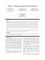
1
GIDeS++: A Rapid Prototyping Tool for Mould Design
Joaquim A. Jorge
Nelson F. Silva
Tiago D. Cardoso
Dep. de Eng.ª Informática
IST/UTL
Av. Rovisco Pais, Lisboa
[email protected]
Instituto Superior Técnico
Av. Rovisco Pais, Lisboa
[email protected]
Instituto Superior Técnico
Av. Rovisco Pais, Lisboa
[email protected]
João P. Pereira
Dep. de Eng.ª Informática
ISEP/INESC
R. de São Tomé, Porto
[email protected]
Abstract
With the advent of new interaction techniques and supporting hardware we should look beyond traditional
WIMP (Windows, Icons, Menus, and Pointers) interfaces. Mouse and keyboard are by far the most widespread
input devices and have been around for a good many years. However, before these, designers have been using
pen and paper for an even longer period. Indeed, the first 3D drawings were sketched from simple perspective
drawings. In this document we describe GIDeS++, a tool that adopts the paper-and-pencil metaphor to bridge
the gap between designers’ and modellers’ innate ability at freehand drawing and the more elaborate and
structured methods required by traditional CAD systems. GIDeS++ offers handwriting recognition for both
gestures and measures, combined speech recognition as an alternative to floating toolbars and a set of
innovative, simple and efficient tools that allow for quick prototyping and modification of three-dimensional
shapes.
GIDeS++ has been developed in close contact with modellers from the mould industry to derive a robust,
powerful, yet natural and simple application that runs on a Tablet PC to allow for "on-site" prototype creation.
Further, using a mobile platform should also ease discussion with clients.
Keywords
Mould Design, Prototyping, Interaction Techniques, 3D Modelling, Sketching, Gesture Interfaces, Calligraphic
Interfaces, Handwriting Recognition, Voice Recognition.
1. INTRODUCTION
The evolution of computer-aided design systems has been
characterized, amongst other aspects, by the fact that its
remarkable increment in functionality was obtained at the
cost of an undesirable increase in the complexity of its
use and of a consequent distance in relation to traditional
paper and pencil. The abundance of existing commands
and the strictness of the interaction tend to interfere with
the designer’s mind and disturb her/his creative
processes, so it’s not surprising that users continue to rely
on paper and pencil in the initial stages of the design,
resorting to computers only in the final stages, when the
shape of the object being created is already established
and it is important to convert the sketch into a precise
drawing.
There is, therefore, a gap between paper and pencil of
simple and passive use on the one hand, and the complex
and less natural professional CAD systems on the other.
GIDeS++ (Gesture-based Interactive Design System)
intends to fulfil this gap in two different ways: first, by
adopting sketching as its main interaction paradigm, it
allows modellers to draw in the same natural way they
usually do when they use a pencil and a piece of paper;
second, by providing precision mechanisms such as
geometric constraints, construction lines and measuring, it
gives users the ability to create substantially complex and
precise technical drawings.
With only a pen the user is able to create primitives by
issuing simple gestures. These objects are positioned in
an intelligent way relative to existing ones. Most
operations are implicit in the sense that the system
attempts to “guess” what the user is trying to do.
Moreover, having a suggestion mechanism allows
GIDeS++ to minimize user’s actions and allowing
freehand drawing gives a very natural feel to the whole
process.
All common manipulation tools are present but with new
improved features. Effort was put into developing high-
level tools that take the user away from the common
control-point manipulation approach. Still, if the work is
to be used it must be accurate so the system is
complemented with a measure system that allows quick
setting of object sizes and thus one is able to export the
models created to any CAD system for further work.
On top of this a multimodal interface was developed,
featuring voice-recognition for invoking commands as
well as handwriting recognition for writing down
measures of objects. Replacing a more conventional
WIMP interface with this kind of user input gives this
system an edge regarding quick prototyping of models.
2. PREVIOUS WORK
A system like GIDeS++ presents several innovative
concepts and some of these had already been thought out
so merits go to previous work done by very creative
people.
As stated before, the main reference for this project is an
older version of the system developed by Pereira: GIDeS
[1]. It was a calligraphic RISC interface for a modelling
system built upon the IRIT modelling kernel.
Several interesting and original ideas were presented in
this application, from the ambiguity solving expectation
lists to very simple and powerful tools like cutting and
gluing that provide high-level operations with a very
natural interface.
3. EXPECTATION LIST
On the most noticeable solutions that resulted from the
development of this system were Expectation Lists
(Figure 1).
designers, the following stage consists of having a
specialized CAD technician to take the product of this
conception phase, which is usually drawn in freehand,
and port it to an exact computer three-dee model.
By providing a more natural and pleasant, interface
instead of the traditional WIMP ones found in
commercial packages, one hopes to close this gap and
“build” a bridge between these two stages, motivating
designers to draw free-hand directly on a CAD system,
allowing them to quickly prototype models that can easily
be changed to follow the so usually strict requirement
measures and constraints.
5. MEASURES LAYER
Being a sketch-based modeller, no precision in the object
creation input can be assured. Unlike other CAD systems,
where dimensions of objects are defined as they are being
constructed, GIDeS++ 3D primitives are assembled from
strokes, which can’t guarantee any precision when it
comes to measures. Even with the help of some kind of
ruler or a grid with defined unit size, the user cannot be
accurate enough.
One efficient way to define proportions, but not real
measures, is to use support lines with geometric
constructions. Even though this is of great help and has an
enormous potential, it doesn’t unravel the entire problem.
Taking this into account, one possibility to resolve it was
to create a special layer where the users could check
edge’s dimensions and other object measures and be able
to change them as well. There were a few intricacies in
the construction of the interface that would allow the user
to do such things.
Firstly, how would the user change to this layer? Would
there be any explicit information that would point us out
how to do so? And then, the other logic questions, how
could an interface that would both maintain the
naturalness be created, following the paper sketch
analogy but always having in mind that the less activity
the user needs to do, the better!
Figure 1 – Expectation List
These allowed the system to deal with the ambiguity of
the input provided by user strokes by displaying a list of
the possible most likely interpretations given a certain
context, behaving as a RISC application, with a small
amount of commands and a high set of possible
operations, as it is seen on Figure 1 above.
These non-intrusive context-based dynamic lists free
users from memorizing modelling gestures and
constructs.
4. MULTIMODAL INTERFACE
Intelligent Multimodal Interfaces have come a long way
and are currently being applied with success in many
areas. Providing an interface that enables a user to
interact with a system in a more natural way is one of the
main goals of this upcoming research subject.
Looking at the usual workflow of any manufactured piece
one can see that most of the creative work is done by
Staying in the measures layer is obvious that the user
wants to visualize as easily as possible the object’s
dimensions. The first approach to this problem was to
show every edge measure from a selected object. But
soon enough one realized that this was too much
information and could even be impossible to show it all at
once.
It was also noticed that if one knows an edge’s size, by
proportion analogy, the size of the others can be easily
speculated and consequently there were no reasons to
report more that one measure at a time. Well, this
probably isn’t entirely true, but knowing which edges
were important to inform at a given moment is a much too
complex and non-trivial and we would have efforts would
have been wasted and other, more important, areas might
have been neglected.
The idea was to have a way of easily and quickly
displaying an edge’s measure permitting the user to verify
a vast number of edges in a short period of time. A
solution was found, one that is plain, simple and efficient:
as the mouse moves over and edge, automatically that
edge – from one vertex to the other - is highlighted and
numeric indication appears, stating the edge’s length.
Finally, the only thing left was a method to allow measure
changes. Initially, the objective was to copy the way
designers and architects set measures. This is usually
achieved by stroking two lines, both starting near vertexes
and stating the measure in the middle of them. As a result,
changing a measure in GIDeS++ would be performed in
the same way. The user draws a line starting from a
desired vertex and then from another and the length
between these two vertexes would come into sight.
Posterior to this, the user would specify the new length
and the change is performed. As another possibility, the
users can simply ignore this measure and continue to
perform other action, enabling the visualization of
distances between vertexes not linked by an object edge.
Still the user had always to stroke two lines and just then
would he be able to make any changes. So and keeping in
mind that simple and easy is better, a complementary way
of setting measures was implemented. Simply by clicking
over an object’s edge, the user is allowed to change it. Of
course this solution only has some vertexes combinations
in mind, but we could always recur to the previous
technique for others.
A particular and important moment was when the user
would specify the new length. The use of the keyboard
was out of the question as this application was, since the
beginning, thought to be interacted with non-conventional
input like mouse or keyboard.
Showing a little numeric keyboard in a frame with special
characters like coma or point wasn’t very convincing,
stylish or even efficient. The logic way was to turn to
handwriting recognition. This was the most natural,
pleasant and efficient way to input measures. Not only is
it quick, but also designers are used to write measures
down on paper.
Therefore, a grey frame appears in the screen and the user
can simply write down the desired number.
To recognize handwriting, one resorted to Microsoft’s
new Handwriting Recognition that is part of Windows XP
Tablet PC Edition [2].
The recognizer gives us the power to recognize, in an
efficient way, human writing. Some tests were performed
to test the recognizer liability and success rate.
6. VISUAL ENHANCEMENTS
Visually, several changes were introduced since the first
versions. It tries to create a more pleasant visual
environment, which can be catchier and more enjoyable
for the user. The first noticeable differences reside on
colour changes, such as the background and user stroke
and remaining lines. Some other changes were introduced
in the visual feedback provided as a result of user
interaction.
As for the Expectation Lists, we concluded that imposing
the upper-left position on the screen had many
disadvantages and could turn the experience of selecting a
suggestion into an annoying process. Consequently, it was
changed so that the user could move it around like a
floating frame and every time this list appears, it is
displayed in the last place it was left. Another
enhancement, resulted from usability tests conducted in
Marinha Grande, was the possibility of positioning the list
near the mouse cursor and applying transparency in order
to better integrate the list with the environment and be
less intrusive.
Objects were also part of the “face-lifting”. One wanted
to create a use experience that resembled somehow
computer games, which try to be attractive and visually
appealing, involving the user in a deeper level. As part of
this plan, some graphic effects were added enriching not
only the application’s aspect, but also the visual
information received by the user.
The first effect applied was Motion Blur to camera view
changes. When a determined view angle is chosen an
animation is performed, changing the camera’s
orientation and zooming on the desired entity. During the
animation, the well known motion blur effect provides
realism since humans see real life in this manner and
gives better notion of how the camera is moving and in
what way is the scene being watched.
Another effect was applied to object selection. When an
object is selected, a glow effect appears, highlighting the
object. This is not only stunning and elegant, but this
glow has the particularity of being present even when the
object is behind another. A sort of ghost object appears
when the object hides at the back of another, enlightening
the user about its position, orientation and about its shape.
This information can be important when using real time
object manipulators, like real time rotation or translation,
since one can follow the object at all time, allowing
adjustments to the object even when it is under another
one.
When performing Boolean operations, this effect could
be of a great help too, as one can watch an object part
inside the other, seeing, if it is the case of a subtraction or
intersection, what will result from that operation.
Finally, as the camera point of view changes and a part of
a selected object gets behind another one, we can still see
it, allowing us to see all objects while changing the view,
without moving the other object or isolating the selected
one.
7. SHADING TECHNIQUES
While most systems aim for realistic rendering
techniques, these might not be the best of tools for
modelling purposes. Perhaps a new, different kind of
shading would allow modellers to focus on the overall
geometry of an object and its finer details.
Trying to withdraw some conclusions one decided to
develop some examples of both of these techniques by
providing shaders with special secular components, for
giving some simple light refraction effects, and others
with only diffuse component but presenting an object’s
silhouette and creases to the user.
description of these new tools is presented next in their
finished and ready-to-use version.
In order to experiment with these realistic and non-photo
realistic rendering techniques, greater control of the
graphics pipeline had to be achieved.
Recent advances on GPUs (Graphic Processing Units)
allow one to harness and use all its processing power.
Still, until recently this could only be done by coding
shaders in Assembly language.
Shading code written in a high-level language is much
easier to read and understand. It also allows new shaders
to be easily created by modifying previously written
shaders.
Figure 3 – 2D Constraints
For starters, 2D Constraints were added.
These particular Constraints are merely constructive as
one isn’t able to directly manipulate sketches. For this
reason and as showed in Figure 3, they were put in the
expectation list. After the user drawing a stroke, if a
constraint is perceived, the result will be introduced in the
suggestion list as one more possibility.
The set of possible constraints - parallel, perpendicular,
tangent and tangent-perpendicular lines - is operational
and can be of great help to designers when making
precise drawings.
Ideas were maintained for 2D/3D constrains. The
feedback is similar, being the only difference the fact that
now edges and faces of object act as restrictive agents and
not the 2D graph itself.
Figure 2 – Shading techniques examples
So one had to look into the available high-level shader
programming languages available. There are, at the
present time, two major options: Cg [3], developed by
nVidia and offered to the OpenGL ARB, and HLSL,
which was created by Microsoft and can be used only
with DirectX. Since the graphics library used by
GIDeS++ is OpenGL, Cg was the obvious choice and it is
very well documented and as, in fact, been used in several
computer graphics courses as an invaluable tool for
teaching all about illumination and shading techniques.
At the present time, as one can observe in Figure 2, both
thin film technique and toon shading are already
implemented and can be mix in the same scene even with
the hidden line rendering that shows object’s edge even in
occult parts.
8. CONSTRUCTIVE CONSTRAINTS
Many new features, most of them regarding constraints,
were designed and put in line to be implemented. A
Regarding object manipulation on a more edition level
instead of merely constructive, new features were also
added. Firstly and most important, the section
manipulation tool adds a new interaction process. This
new process reassembles direct manipulation and a
preview of a possible final result is shown real-time. It
only reassembles direct manipulation as the object isn’t
actually changed until the action is committed and it still
depend on sketch because the user interaction is
analogous to an indication of “this edge putted here” by
drawing a line and therefore changing the section size.
Still this was different enough from the pure-sketch
scheme and so it had to be validated.
Figure 4 – Hole Section
Manipulation
Figure 5 – Section
Manipulation
In Figures 4 and 5 one can see the interaction with section
manipulation operator. Firstly, the user picks the wanted
edge/section to change, and then a preview, presented in
the figures, will appear showing the result in the main
working face. A special-effect animation will mark the
original section and an animated arrow will spot from the
centre of the section till the cursor. Along with these two
indications, the top surface is also extended so that the
user can preview its final look and be assuring of the
result. If this extension overlaps the surface itself then the
portion that will disappear with when committing will
show up in another colour, which is blue by now.
In a more technical approach, the result of this operation
is an offset of the remaining face of the section. Besides
the top and main face, where the preview will show up,
other faces connected to the section will offset to fulfil
the preview and the remaining faces will morph to close
the object and connect to those offset faces.
The user can then enlarge or shrink a section by pulling it,
enabling more control and more edition-power over
objects. Being holes so important to moulds industry, it’s
crucial to be able to edit them as quickly as possible and
with the great amount of control as possible. This
operation is then a successful step towards the goal.
Following the same kind of interaction, a new tool, Move
Sections, was also devised. It allows for quick
repositioning of object’s portions, meaning that holes can
easily be moved along the face they’re caved in.
With these two tools, mould modellers have the ability to
discuss cold runners and injection holes size, position and
overall specifications online with customers, bringing a
slight edge in comparison with conventional cad systems.
Generalizing this notion, almost any component of an
object can be easily and quickly erased, having therefore
independence between them.
An object’s component isn’t just considered an object’s
bumps or holes; it can be a top face, a hole’s bottom, a
corner fillet, a chamfer or anything else that by common
sense can be taken out. Some examples of this tool’s
potential can be viewed in Figure 6. The top examples
result both in a simple box, however the other two
illustrate a particular case and its result.
Finally, the last but not least new feature is equal-sized
edges operation. Until now, making two edges have the
same length was a two-step process. One had first to view
the measure for the source edge, and then select a
destination edge and input the right size.
8.1 Usability test and results
Upon implementing all these new features, a new
GIDeS++ prototype was developed. There was the need
to test and evaluate it, so a usability test took place at
CENTIMFE’s headquarters, in Marinha Grande,
Portugal, on the 26th of March with the participation of
five users with different experience and task in mould
industry.
This usability test had also in agenda the validation of
different kinds of non-photorealistic rendering and the
expectation list as a way of dealing with ambiguity.
Users found the list to work better when it is presented
immediately near the cursor. This is a different approach
to the one in the previous GIDeS versions. On top of this
a new conclusion was drawn from the tests, there must be
a quick way to show/hide the list since once one is
accustomed to the system it might be more of an obstacle
than a help, as one “learns” to have the first suggestion
right. Furthermore, transparency proved to be a natural
way to better integrate the list in the working
environment. All these changes to the list will enforce us
to take another approach at it.
In what regards constraints, the feature that caused the
greater impact was delete holes as this proves very simple
and efficient and a valuable aid in mould modification.
Figure 6 – Delete Tool
Another feature introduced, within object space, is holes
deleting tool. This new tool has the potential to remove a
hole by scratching over it. Regarding the interface, this
follows another idea. As scratching was already used with
great success in deleting other entities, like lines or
objects, it was only common sense to continue this kind
of interaction to any other deleting tool as long as
possible.
Another aspect notice was the higher rating added by
Hole Section Manipulation over Section Manipulation.
This only accentuates the importance of holes in object
edition.
On the overall all new features were very welcome and
received high marks and most comments concerned only
to small details regarding the interface or visualization.
Concerning shading techniques, it is easy to conclude that
CAD technicians welcome any new rendering method.
Perhaps tired of the dull interfaces found in usual CAD
applications, photo-realism is the most appreciated, as it
can give them a better notion of what the final product
will look like. At least one non-photo realistic and one
more realistic should be present, thus allowing users to
have a more simplistic view for use during the modelling
process and a more detailed one which can be used for
details and realistic preview.
Another important result drawn from this evaluation
session was that hidden lines are without doubt a plus to
GIDeS++ as it gives better perception of the object as a
whole.
To sum up, all expectations for this evaluation session
were fulfilled and even surpassed, unveiling the right path
of development of GIDeS++ in near future.
9. CONCLUSION
Porting of the old GIDeS system was successful and the
new version introduced several enhancements regarding
its architecture and modularity. Thus, if furthers
modifications are to be made it certainly is now a fairly
easy task.
Regarding the overall functionality it is clear that the
existing gap, between the design and modelling stages of
a production process, can be shortened by this system.
The free-hand drawing allowing simple sketching of
three-dee models, allied with the new measures layer
allows for designers and modellers to use a common tool,
where a prototype can be created and exported to inhouse CAD systems.
Delegating a major role to holes proved to be a right
choice as mould creation becomes easy to built and
modify, even in real time with clients.
On top of this, the whole new multimodal interface also
brings a set of new features to GIDeS++, specially the
handwriting recognition, which is a clear case of success.
Voice recognition would allow for an interface with no
toolbars or menus whatsoever but users were not that
comfortable with it and it is regarded as an alternative [4].
Still, it was also well accepted and with good results.
On the overall, GIDeS++ is developing in the right
direction and at a great pace, bringing together rapid
prototype development and CAD precision and power.
10. ACKNOWLEDGMENTS
The work described in this paper has been supported in
part by the European Commission Grant #IST-200028169 (SmartSketches project) and by the Portuguese
Science Foundation under grant POSI/34672/SRI/2000.
Further thanks go to all testers of the GIDeS++ system,
including modellers from CENTIMFE as well as friends
and colleagues.
11. REFERENCES
[1] Pereira J. P., Jorge J. A., Branco V. A., Ferreira F. N.:
GIDeS: Uma Abordagem Caligráfica à Edição, 9º
Encontro Português de Computação Gráfica, 2000
[2] Microsoft Tablet PC Platform SDK Documentation,
http://msdn.microsoft.com/tabletpc
[3] nVidia: Cg Toolkit – User’s Manual,
http://developer.nvidia.com/page/cg_main.html
[4] J. Jorge, N. Silva, T. Cardoso, GIDeS++, 12º EPCG,
2003