1
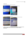
Argus 4bay
SATA II-to-SATA II
RAID Subsystem
Model Name : MBSMBS-400
User Manual
Version 1.0
Argus 4bay SATA II-to-SATA II RAID Subsystem
Guide to configure HRD with MBS
1. internal setup of SATA cable(pic1.1) with e-SATA port(1.2) and HDD
port(1.3)
1.1.
1.2.
1.3.
2. external setup of e-SATA cable(pic2.1) with HRD’s e-SATA port(2.1) and
MBS’s e-SATA port(2.2)
2.1
2.2
2
Quick Setup Guide
Argus 4bay SATA II-to-SATA II RAID Subsystem
3. HRD setup
3.1 HRD will automatically recognize extra storage
3.2 HDD clear(menu/device/HDD clear)
3.3 HDD clear(tick select all/ click start)
3.4 to check at menu/system information/storage
4. MBS setup: while turning on MBS, please keep pushing sw1 button(from the
back panel of MBS, brown). This will refresh the setting of raid(0-9)
automatically.
Quick Setup Guide
3
Argus 4bay SATA II-to-SATA II RAID Subsystem
Table of Contents
Chapter 1 Product Introduction ..........................................................
..........................................................5
.......................... 5
1.1 Front View ................................................................................................5
1.2 Rear View .................................................................................................6
1.3 Disk Drive Status Indicators: ..........................................................................7
1.4 Disk Drive Installation Steps:..........................................................................7
1.5 RAID Concepts ..........................................................................................8
1.5.1 Definition of RAID Levels ........................................................................8
1.6 RAID Modes............................................................................................ 11
Chapter 2 Getting Started ..............................................................
.............................................................. 13
2.1 Preparing the Subsystem ............................................................................ 13
2.2 Raid Configuration Steps ............................................................................ 14
2.3 Deleting RAID Configuration ........................................................................ 15
4
Quick Setup Guide
Argus 4bay SATA II-to-SATA II RAID Subsystem
Chapter 1 Product Introduction
1.1 Front View
Front Panel LEDs
Part
Function
Fan Fail LED
LED is off means Fan is good.
Orange LED means Fan has failed.
Over Temp LED
LED is off means Temperature is normal.
Orange LED means Temperature exceeded normal range.
Power On LED
Green LED means RAID subsystem is powered on.
Quick Setup Guide
5
Argus 4bay SATA II-to-SATA II RAID Subsystem
1.2 Rear View
Rear View Parts
eSATA Port
The subsystem has one external SATA port for connecting to Host/Server.
Switch 1
After setting the dial of Switch 2, press this switch during power on to
apply the selected RAID level or clear the RAID level.
Switch 2
Use this to select the dial and set the RAID level or clear the RAID level.
Mute
Use this to silence the alarm beeper.
Fan
The fan provides proper ventilation for the RAID subsystem.
Power On Switch
Use the Power On Switch to turn on or off the RAID subsystem.
Power Input Socket
Use the Power Input Socket for connecting the power cable.
6
Quick Setup Guide
Argus 4bay SATA II-to-SATA II RAID Subsystem
1.3 Disk Drive Status Indicators:
Every Drive Carrier has 2 status indicator lights. One indicator light is Disk Fault
Indicator. When this light is GREEN the disk is powered on and everything is
functioning normally. When the Disk Fault Indicator light is RED, the drive has failed
or a drive error has occurred which requires the user’s attention.
The other status indicator light is the Disk Access Indicator. When the hard disk drive
is busy or being accessed, this light will flash BLUE.
1.4 Disk Drive Installation Steps:
1. To remove the disk tray from disk slot, make sure it is in unlocked position (lock
groove is vertical). Then press the Carrier Open button.
2. The tray handle will flip open. Pull out the disk tray.
3. Place the disk drive in the disk tray. Make sure the holes of the disk drive align
with the holes of the disk tray.
4. Tighten the mounting screws to secure the disk drive into the disk tray.
5. Insert the disk tray with disk drive in the disk slot.
6. Close the tray handle until the latch click into place.
Quick Setup Guide
7
Argus 4bay SATA II-to-SATA II RAID Subsystem
1.5 RAID Concepts
The basic idea of RAID (Redundant Array of Independent Disks) is to combine multiple
inexpensive disk drives into an array of disk drives to obtain performance, capacity and
reliability that exceeds that of a single large drive. The array of drives appears to the
host computer as a single logical drive.
The RAID subsystem provides data striping, mirroring, XOR calculation and data
verification. It supports RAID levels 0, 1, 3, 5, 10, JBOD and CLONE. All RAID levels’
capacity can exceed 2 Terabytes. The RAID subsystem behaves as a full 48-bit
addressing RAID drive and is 100% ATA compliance.
From (PC) host controller, each logical device (RAID volume) controlled by the RAID
system acts just the same as single regular hard disk although a RAID system generally
consists of more than one hard disk drives. Therefore, no extra BIOS, driver or software
is needed.
1.5.1 Definition of RAID Levels
Striping (RAID 0) for High Performance
Striping or RAID 0 is the segmentation of logically sequential
data, such as a single file, so that segment can be assigned to
multiple hard disks in a round-robin fashion and thus written
concurrently.
Advantage of RAID 0 is to achieve high performance by
accumulating each individual hard disk performance. However,
if any one hard disk gets defective, information stored in this
RAID 0 will become invalid.
The RAID subsystem will just make use of the same disk
space for each hard disk under RAID 0 condition. For example,
if a RAID 0 consists of 5 different size hard disks, the total
usable space of this RAID 0 will be [capacity of smallest size
hard disk] * [the number of hard disks in this RAID 0].
Mirror (RAID 1) for High Security
Mirror or RAID1 is the replication of data onto separate hard
disk in real time to ensure continuous availability. In a RAID 1
system with two hard disks, the data in one hard disk will be
exactly the same as the data in the other hard disk.
The RAID subsystem will also make use of same size disk
space in each hard disk in RAID 1. That is, the RAID controller
will write data to the same disk space in each hard disk. When
reading data, the RAID controller will read data from a
specified hard disk.
8
Quick Setup Guide
Argus 4bay SATA II-to-SATA II RAID Subsystem
Failure in a hard disk will cause the RAID controller to enter into degraded mode. The
host controller can still read/write data to the RAID without knowing any hard disk defect.
Users have to replace the hard disk then the RAID controller will enter in on-line rebuild
mode automatically.
Besides, if there is only partial defect in a hard disk, the RAID controller will read data
from the other healthy hard drive.
Stripe + Mirror (RAID 10) for High
Performance and High Security
RAID subsystem could be configured to
support Stripe and Mirror at the same
time, i.e. RAID 10. Take four hard
drives in RAID 10 as an example. Hard
drive 0 and hard drive 1 could act as
Mirror 1. Hard drive 2 and hard drive 3
act as Mirror 1 too. The RAID controller
then configures these two Mirrors as
Stripe.
At least two drives (either one in each
Mirror) can be allowed to fail without
any impact to RAID data access. If two
drives from the same Mirror are failed,
the RAID data is not accessible and
becomes invalid.
CLONE
Clone’s action is similar to RAID 1.
However, all of the hard disks will be
the mirrors. For example, in a four hard
drives Clone environment, data in each
hard drive will be the same. This mode
is useful especially when users would
like to copy data from a hard drive to
several hard drives at the same time.
The number of allowed failed drives is
the total number of drives in the RAID
minus one.
Quick Setup Guide
9
Argus 4bay SATA II-to-SATA II RAID Subsystem
Concatenating (Large)
This mode is also named “Large”. In this mode,
the RAID controller will concatenate all of the hard
drives into a single hard drive with larger capacity.
For example, if three 500GB hard disks are
connected to the RAID subsystem in Large Mode,
user will get a single hard disk with capacity of
1,500GB.
If any one hard disk gets defective, information
stored in this LARGE RAID will become invalid.
Parity Protection (RAID 3 and RAID 5)
The XOR engine in the RAID controller
generates parity block. In RAID 3 mode,
parity block will be stored in the same hard
disk drive. In RAID 5 mode, parity block will
be spread over all of the different hard
drives.
The RAID controller will also make use of
the same size disk space in each hard disk
under RAID 3 / RAID 5 condition.
Failure in a hard disk will cause the RAID
controller to enter into degraded mode. Host
controller still could rear/write data thru the
RAID normally without knowing any defects.
Users have to replace the defective hard
disk. The RAID controller will then enter into
online-auto-rebuild mode automatically.
10
Quick Setup Guide
Argus 4bay SATA II-to-SATA II RAID Subsystem
1.6 RAID Modes
Normal Mode
Normal mode means all of the configured hard drives exist and in good condition and the
RAID controller is not in rebuild condition.
Degrade Mode
In degrade mode, some hard disk in RAID is removed or defective. No other RAID drive
is under rebuilding condition. The firmware or application will so some process to warn
users the need to replace the defective hard disk with a healthy one.
Rebuild Mode
Rebuild mode means a RAID drive is doing data recovery. Only when host controller
does not access RAID hard disks, the RAID controller will resume rebuild mechanism.
Rebuild will be paused any time when host controller is executing commands.
Only a defective hard drive will be rebuilt each time. For example, if more than one hard
disk is defective in RAID 10/Clone mode, a defective hard drive will be rebuilt only after
the previous defective one is rebuilt successfully.
Broken Mode
Broken mode means the number of hard disk is not enough to keep RAID run normally.
RAID hard disks then will just keep some basic communication functions with application.
No other data access is allowed.
If broken mode is caused by RAID hard disk defect, the RAID drive will crash. However,
if the broken mode is caused by just removing some hard disks and those removed hard
disks’ data remain unchanged, the RAID controller will enter normal mode or degrade
mode when the hard disks are connected to the RAID controller again.
On-line Hot Spare
Spare hard disks which have not been used initially by the RAID controller can be
accessed when the RAID controller needs more hard disks afterward.
The RAID controller uses spare hard disks in auto mode, where the initially un-used hard
disks will just stand by. When needed, the RAID controller will use these hard disks
automatically.
Quick Setup Guide
11
Argus 4bay SATA II-to-SATA II RAID Subsystem
On-line Auto Rebuild
When the RAID controller enters degraded mode, it will search possible spare drive to do
RAID rebuild automatically with the following searching priority:
1. Search the original RAID drive related hard disk.
2. Search the previously reserved spare hard disk.
3. In auto mode, if there is a stand-by hard disk which is not a member of an
existing RAID, the RAID controller will use it.
The RAID controller will automatically rebuild the system when no host controller
commands are executed. The firmware or application is able to specify
1. The time interval between two rebuild actions, or
2. When the RAID controller will start rebuild after host controller is idle.
Up-to-date rebuild status will be recorded in RAID hard disks. When rebuild process is
terminated for some reason, the RAID controller will resume the rebuild from the same
place where it is interrupted last time. There is no need to rebuild from the beginning.
On-line Command Based Bad Sector Recovery
Hard disk might be defective in some sectors. When the defect causes write operation
error in system, O.S. (e.g. Windows or Linux) will do some error handling to prevent
users from using these defective sectors. However, when there are problems in reading
operation, some important data might be lost.
The RAID controller supports command based bad sector recovery mechanism to secure
read operation in RAID 1/3/5/10 and CLONE modes. If read error occur, the RAID
controller marks this hard disk status “non-readable”. While host controller tries to read
the defective region again, the RAID controller will read it just like in degrade mode.
That is, data in the “non-readable” hard disk is recovered by some special algorithm.
Only RAID 10 and CLONE modes allow more than one defective hard disks. After the
RAID controller starts command based bad sector recovery algorithm, firmware or
application will inform users the status so that user could decide whether to replace the
defective hard disk right away.
12
Quick Setup Guide
Argus 4bay SATA II-to-SATA II RAID Subsystem
Chapter 2 Getting Started
2.1 Preparing the Subsystem
1. Connect the eSATA cable to the eSATA port. Connect the other end of eSATA
cable to the Host computer.
2. Connect the power cable to the AC Power Input Socket. Connect the other end to
the power source.
Quick Setup Guide
13
Argus 4bay SATA II-to-SATA II RAID Subsystem
2.2 Raid Configuration Steps
1. Configure the RAID Level by rotating the SW2 switch dial.
NOTE: “6” is not used. “7” is used to clear RAID configuration.
RAID
Level
No. of
Allowed
Failed
Drives
0
None
Block striping is provided and yields higher
performance than with individual drives. There
is no redundancy.
2
1 (2)
Drives are paired and mirrored. All data is
100% duplicated on an equivalent drive. Fully
redundant. RAID 1 if use 2 drives; RAID 10 if
use 4 drives.
2
LARGE
None
Large is similar to RAID 0 in that it
concatenates the capacity of all member drives.
The data is written linearly starting with the
first disk drive. When first disk drive becomes
full, the next disk drive is used. Large can have
2 or more disk drives. There is no data
redundancy.
2
CLONE
No. of
drives
minus 1
3
1
Data is striped across several physical drives.
Parity protection is used for data redundancy.
3
5
1
Data is striped across several physical drives.
Parity protection is used for data redundancy.
3
1 (10)
Description
Clone provides multiple copies of data in a disk
drive. Clone can have 2 or more disk drives.
2. While holding SW1, press the Power On Switch.
3. Verify that the RAID volume is detected in the Host computer.
IMPORTANT: Before any RAID MODE change, clear the RAID
configuration first using the steps in the next page.
14
Quick Setup Guide
Min. # of
Drives
2
Argus 4bay SATA II-to-SATA II RAID Subsystem
2.3 Deleting RAID Configuration
1. To clear RAID MODE, rotate the SW2 switch dial to “7”.
2. While holding SW1, press the Power On Switch.
3. The RAID level will be deleted. At the same time, the eSATA Port Multiplier will
function.
Quick Setup Guide
15