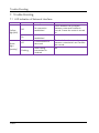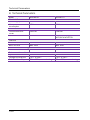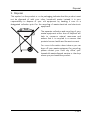
1
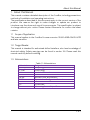
Contents Contents 1. About this Manual ..................................................................................... 3 1.1 1.2 1.3 Scope of Application ...................................................................................................................3 Target Reader .................................................................................................................................3 Abbreviations ..................................................................................................................................3 2. Introduction ................................................................................................ 4 2.1 2.2 2.3 2.4 2.5 2.6 Product Overview .........................................................................................................................4 Function and Feature .................................................................................................................4 Scope of Application ...................................................................................................................4 Scope of Delivery .........................................................................................................................5 Environment and Attention .....................................................................................................5 Safety Symbols .............................................................................................................................5 3. Mounting ..................................................................................................... 6 3.1 Preparation .......................................................................................................................................6 3.2 Assemble the ComBox ..............................................................................................................6 4. Connect to Internet .................................................................................... 7 4.1 Connecting via Ethernet ............................................................................................................ 7 4.2 * Connecting via WiFi ................................................................................................................. 8 5. Web Server .............................................................................................. 10 5.1 5.2 5.3 5.4 5.5 Visiting the Web Server ..........................................................................................................10 Home .................................................................................................................................................. 11 Ethernet ............................................................................................................................................ 11 Advanced .........................................................................................................................................12 *Wireless ....................................................................................................................................... 20 6. Solarcloud ................................................................................................ 22 6.1 6.2 6.3 6.4 6.5 6.6 6.7 Account Registration ...............................................................................................................22 Create a PV plant .......................................................................................................................24 Browse PV plant ........................................................................................................................26 Add a ComBox .............................................................................................................................26 PV Plant Sharing ........................................................................................................................ 27 Configuration Report................................................................................................................ 27 Mobile device Monitoring .......................................................................................................28 ~1~ Contents 7. Trouble Shooting..................................................................................... 30 7.1 LED Indication of Network Interface ..............................................................................30 7.2 FAQ ..................................................................................................................................................... 31 8. Technical Parameters ............................................................................. 32 9. Disposal ................................................................................................... 33 10. ContactUs .............................................................................................. 34 ~2~ About this Manual 1. About this Manual This manual contains a detailed description of the ComBox, including precautions, methods of installation and operating instructions. The specifications described in this document apply to the current version of the product. We reserve the right to make changes or update our product to introduce new functions and overall improvements. This specification is subject to change without prior notice. Please contact Zeversolar to confirm the latest revision. 1.1 Scope of Application This manual applies to the ComBox firmware version 15430-408R+15429-407R and later versions. 1.2 Target Reader This manual is intended for authorized skilled installers, who have knowledge of electrical safety. Safety warnings can be found in section 2.6. Please read this manual carefully before installing. 1.3 Abbreviations Table 1-1: Abbreviations Abbreviation E-Today E-Total LAN WAN WLAN DHCP DNS PV Pac Designation Daily Energy Total Energy Local Area Network Wide Area Network Wireless Local Area Network Dynamic Host Configuration Protocol Domain Name Server Photovoltaic Alternating Current Output Power ~3~ Introduction 2. Introduction The monitoring system plays an important role in the PV plant. Users can view the PV Plants power generation data and fault information to avoid unnecessary loss of power and non-scheduled downtime. Users can also maximize the energy generating efficiency according to power generating data and report. ComBox has two versions: ComBox and ComBox WiFi. 2.1 Product Overview The ComBox is an integrated monitoring device, which can be installed inside the inverter, and collects the inverter’s data and events in the PV plant. When an Internet connection is present, the ComBox will upload the collected data to the Solarcloud to facilitate on-line web monitoring and data analysis. The system structure shows in Fig. 2-1. Fig.2-1: System structure 2.2 Function and Feature PV Plant monitoring via the Solarcloud Remote monitoring via Ethernet or WiFi Power Management Capability Support Micro SD card save data Integrated memory Online firmware updating 2.3 Scope of Application ComBox can be installed in the following inverters: Zeverlution 1000S-3000S Zeverlution 3000SE-3680SE ~4~ Introduction The sections marked with a * apply to the WiFi version. 2.4 Scope of Delivery The details information about Scope of Delivery please refer to the ComBox Quick Installation Guide. 2.5 Environment and Attention The ComBox operational ambient temperature is -25 °C to 75 °C. 2.6 Safety Symbols Please pay attention to the following safety symbols in the manual: Information Provides information about installation or use. Notice Indicates the instructions must be followed in the correct order to prevent problems. Warning Indicates the instructions must be followed in order to prevent serious problems or injuries. ~5~ Mounting 3. Mounting 3.1 Preparation Table 3-1: Preparation Type Network cable Requirements 1. Comply with the standards for structured cabling according to EIA/TIA-568. 2. Shielded Ethernet cable (CAT-5E or higher). 3. UV resistant if used outdoors. Quantity Max. 100m 3.2 Assembling the ComBox 3.2.1 Electrical Checks Risk of lethal electric shock when opening the inverter may cause death or serious injury. Therefore before assembly, ensure that the inverter is isolated from all sources of AC and DC power (see inverter Installation Guide). Electrostatic discharge can damage the inverter. Please ground yourself before touching components by touching the protective conductor (PE) or a non-coated part of the inverter enclosure. 1. 2. In order to ensure safety, before assembly, please read the inverter user manual carefully. Assembly is strictly prohibited when the inverter connected to electricity or is in operation. 3.2.2 Assembly For details regarding mounting please refer to the ComBox Quick Installation Guide. ~6~ Connecting to the Internet 4. Connecting to the Internet The ComBox requires an Internet connection in order to provide remote monitoring via Ethernet or WiFi. The ComBox uses network port #6655 and #80 to communicate with the Solarcloud. Both of these two ports must be opened otherwise the ComBox cannot connect to the Solarcloud and upload data. If the IP address of the ComBox is different from the network segment assigned by the router, Troubleshooting: 1. Make sure the DHCP service of router has been activated if ComBox use DHCP function. 2. Check the connection between the ComBox and the router. 3. Check whether the ComBox was using a fix IP address. 4. If the ComBox cannot obtain an IP address from the router, it will use 169.254.1.100 or 0.0.0.0 4.1 Connecting via Ethernet The ComBox is connected to the Ethernet by simply connecting the Ethernet cable from the router to the Ethernet port. The connection between the ComBox and the Internet is shown in Fig. 4-1. Fig. 4-1: Network connection The ComBox obtains an IP address from the router via DHCP automatically and displays it on the LCD of the inverter. The time it takes to connect to the Internet depends on the network communication conditions. At the same time the router needs to support DHCP services and the DHCP services must be activated if the ComBox has been set up to use the DHCP function. ~7~ Connecting to the Internet 4.2 * Connecting via WiFi If users use the ComBox’s WiFi to connect the router for remote monitoring, the connection diagram is shown in Fig. 4-2. WiFi WLAN Inverter Wireless Router World wide web Fig. 4-2: WiFi connection In order to achieve remote monitoring reliably, the following steps must be taken. Step1: Power on the inverter, which will also power ComBox, and use a mobile device or laptop to search for the wireless access point (AP) of the Combox WiFi. A new AP of ZEVERSOLAR -XXXX is displayed, Select this AP to connect. The password is “zeversolar”. As shown in Fig. 4-3. Fig. 4-3 WiFi connection page 1. "XXXX" stands for the last four digits in the Registry ID of the Combox. Step2: Start the web browser and enter http://160.190.0.1. The internal website opens. Step3: Select the wireless page and select a wireless local network in the area to connect. The Password/Security Key dialog box opens, as shown in Fig. 4-4. ~8~ Connecting to the Internet Fig. 4-4 connect to router Step4: Enter the password of the wireless local network that you wish to connect to. Do not enter the password of the router. Step5: After approximately one minute the WiFi of the ComBox will connect to the wireless local network. The status indicator on the Wireless page should display the icon, as shown in Fig. 4-5. Fig. 4-5 WiFi Connection Instructions ~9~ Web Server 5. Web Server The ComBox has an integrated internal web server. The running state of the inverter can be checked from the internal web server page. You can also enable some advanced functions such as output power limitation and adjusting the inverters safety parameters The interface structure of the built-in web server is shown in Fig. 5-1. Fig. 5-1: Structure of the web server 5.1 Visiting the Web Server There are two ways to visit the internal web server of the ComBox: via Ethernet or via WIFI (if the ComBox is equipped with the WiFi module). 5.1.1 Visiting via Ethernet Input the IP address of the ComBox (shown on the inverter’s LCD) in the browser’s address bar. For example, if the IP address shown on the inverter is 192.168.10.13, then enter 192.168.10.13 in the browser’s address bar and press the Enter key to open the web page, as shown in Fig. 5-2. 5.1.2 *Visiting via WiFi You also can visit the web page via WiFi, please refer to section 4.2. Once you are wirelessly connected to the ComBox, input“160.190.0.1” in the browser’s address bar, press the Enter key to display the internal web page of ComBox, as shown in Fig. 5-2. ~10~ Web Server Fig. 5-2: ComBox Web Server 5.2 Home This page shows the information and state of the ComBox. It also shows the state of the inverter. See Fig. 5-2. If the inverter is working normally, it shows a green icon; otherwise the red icon will be shown. 5.3 Ethernet Clicking the “Ethernet” tab will open the Ethernet page. On this page you can set the Ethernet port parameters. You can set the ComBox using a static IP address or obtaining the IP address automatically. ~ 11 ~ Web Server Fig. 5-3: Ethernet page 5.4 Advanced The Advanced web page shows the advanced settings of the ComBox, Such as the power management and safety setting. In addition, the firmware of the ComBox and Inverter can be upgraded from this webpage. 5.4.1 Power Management The ComBox will regulate the active power of inverter according to value of the installed PV module capacity or the installed inverter capacity or the energy meter reading, which are set by the user. Enter the fit to values in Fig. 5-4. a) Active Power Limit There are two modes of active power limitation can be selected and five values need to set. Fig. 5-4: Set Active Power Limitation Method The following ways will introduce how to configure the two types of power limitation. ~12~ Web Server Based on the installed Solar DC capacity In this method the AC output of the PV system will not exceed a set percentage of the installed solar DC capacity. For example, if a 20 % limitation on a 1,5 kWp PV system connected to an Eversol TL2000 (2 kWac inverter) has been set then the AC output will not exceed 1.2 kWac. The Fig.5-5 shows the system diagram of power limitation based on the installed solar DC capacity Fig. 5-5 System diagram based on the installed solar DC capacity For this method position 1 in Fig. 5-6 should be ticked. For correct operation of this method there are three parameters that must be entered, please refer to Fig. 5-6: Item a – installed solar DC capacity of PV system in Wp; Item b – total inverter AC capacity of PV system in W; Item c – Limitation value of solar DC capacity in %. Click “OK” button in bottom-right of this web page to ensure the setting parameters take effect. ~ 13 ~ Web Server The Fig. 5-6 Set parameters based on the installed solar DC capacity The “output power” value is value a multiplied by value c when P >= a*c, Table 5-1: The indicator of the Item Parameter Definition a The combined peak power of the PV array (Wp) b The sum of the rated powers of all inverters in the PV plant (Wac) c The Percentage of output power limitation based on parameter a P The sum of the real time output power of all inverters in the PV plant Parameter b: This parameter is the key value of power limitation, please ensure that it is correct Based on the Installed Inverter AC Capacity In this method the AC output of the PV system will not exceed a set percentage of the installed inverter AC capacity regardless of the installed DC capacitay. For example, if a 20 % limitation on a 2 kWp PV system connected to an Eversol TL2000 (2 kWac inverter) has been set then the AC output will not exceed 1.6 kWac. Fig. 5-7 is shows the system diagram of power limitation based on the installed AC (inverter) capacity For this method position 2 in Fig. 5-7, should be ticked. For correct operation of this method there are two parameters that must be entered, please refer to Fig. 5-7: Item b – total inverter AC capacity of PV system in W; Item d – Limitation value of AC capacity in %. Click the “OK” button in bottom-right of this web page to ensure the setting parameters take effect. ~14~ Web Server The Fig. 5-7 Set parameters based on the installed solar DC capacity The “output power” value is value b multiplied by value d when P >= b*d Table 5-2: The indicator of the Item Parameter Designation b The sum of the rated power of all inverters in the PV plant (Wac) d The percentage of power output limitation based on parameter b P The sum of the real time output power of all inverters in the PV plant Parameter b: This parameter is the key value of power limitation. Please ensure that it is correct b) Reactive Power Limit There are four modes of reactive power limitation can be selected. Cos(phi) fix mode: In this mode, the ComBox will regulate the reactive power of inverter according to the Cos(phi) value which is set by the user. Enter the Cos(phi) value and choose the phase as shown in Fig.5-8. Fig. 5-8: Cos(phi) fix mode Cos(phi) variable mode: In this mode, the ComBox will produce a curve according to the “P/Pn”, “Cos(phi)” and the phase of points 1,2,3 and 4, and will regulate the reactive power according to this curve, as shown in Fig. 59. ~ 15 ~ Web Server Fig. 5-9: Cos(phi) variable mode Cosφ 0.95 Leading 1 P/Pn 0.2 0.4 0.6 0.8 Lagging 0.95 Fig. 5-10: Cos(phi) variable Cure Q fix mode: In this mode, the ComBox will regulate the reactive power of the inverter according to the Q value which is set by the user. You need to input the Q value and choose the phase as shown in Fig. 5-11. Fig. 5-11: Q fix mode Q variable mode: In this mode, the ComBox will produce a curve according to the “U/Un”, “Q value” and phase position of points 1,2,3 and 4, and will regulate the reactive power according to this curve, as shown in Fig. 5-12. ~16~ Web Server Fig. 5-12: Q variable mode Q 0.50 Leading 1 U/Un 0.96 1.00 1.04 1.08 1.12 Lagging 0.50 Fig. 5-13: Q variable Cure To cancel the output power limit function untick the checkbox and click the “OK” button. Please ensure that the inverter supports the Output Power Limit function. 5.4.2 Safety Setting The ComBox also supports setting the safety parameters of the inverter. Choose the safety standard and then set the protect threshold below. And press the “OK” button. ~ 17 ~ Web Server Fig. 5-14: Safety Parameters 5.4.3 Updating Firmware The ComBox can update the firmware of itself, and can also update the firmware of the connected inverter. The ComBox can distinguish the update file type and update it automatically. Update ComBox firmware Enter the Advanced page and click the “choose file” button and select the new firmware of ComBox and then click the “OK” button to update. ~18~ Web Server Fig. 5-15: Update Firmware Update inverter firmware Enter the Advanced page and click the “choose file” button and select the new firmware of inverter and then click the “OK” button to update. It similar the Fig. 515, but you should choose the relevant inverter firmware file. 5.4.4 Restart Enter the Advanced page of the ComBox and click the “OK” button at the Restart section to restart the device. Fig. 5-16: Restart the device ~ 19 ~ Web Server 5.4.5 Restore to Factory Enter the Advanced page of the ComBox and click the “OK” button in the Restore to Factory section to restore all the parameters of the ComBox to the factory settings. Fig. 5-17: Restore to Factory This operation will delete all user data 5.5 *Wireless This page shows the wireless network of ComBox. You can also configure the wireless network. If you want to change the connected WiFi network, please refer to section 4.2. Fig. 5-18: Wireless Network The wireless network IP information was shown as below. To change these settings please refer to section 5.3. ~20~ Web Server Fig. 5-19: Wireless IP information ~ 21 ~ Solarcloud 6. Solarcloud The Solarcloud is a cloud service platform for users provided by Zeversolar. The ComBox transfers the operation data to the Solarcloud server via the Internet to enable the users to monitor their PV plants and inverters remotely through a computer or a mobile device. You can visit Solarcloud via the following website on a PC: http://solarcloud.zeversolar.com. For the Android application, search for “Solarcloud” in Google play to download and install Solarcloud for on your mobile device. For the iPhone or iPad application, search for “Solarcloud” in the App store of the Apple Corporation and install it on your iPhone or iPad. To monitor the PV plant and inverter with Solarcloud, the ComBox and Internet must be functioning normally. 6.1 Account Registration Users who use Solarcloud for the first time are required to register an account in Solarcloud. Monitoring can then be performed after the user has registered. Step 1: Input http://solarcloud.zeversolar.com in the browser and open the main page of Solarcloud as shown in Fig. 6-1. ~22~ Solarcloud Fig. 6-1: Registration and login page Step 2: Click the button marked with a “1” in Fig .5-1, click “Register” to enter the registration page, and register a user account according to the prompts. Step 3: After the registration has been completed, Solarcloud will send an activation email. Activate your Solarcloud account according to the information in the email. If there is no activation mail in your inbox, please check your spam box. If you did not receive an email from Solarcloud, it could be: 1. The email was identified as junk mail. Please check the spam folder. If the email from Solarcloud was identified as junk mail, please add the address of Solarcloud into your white list to avoid future emails from Solarcloud being identified as junk mail. 2. You may have input an email address which is different from the one you used for registration. Please confirm if the email was sent to another email address. Please reregister if you entered an unknown email address when entering account information. ~ 23 ~ Solarcloud 6.2 Create a PV plant Step1: Enter http://solarcloud.zeversolar.com in the address bar of the browser and open the home page of Solarcloud as shown in Fig. 6-1. Step2: Input your user name and password in the area marked with a “1” in Fig. 61 to login to Solarcloud. If the login is successful you will enter the web page with a PV plant list as shown in Fig. 6-2. Fig. 6-2: Setting up a new PV plant Step3: Click Position 1 in Fig. 6-2 to enter the PV plant establishing page as shown in Fig. 6-3. Follow the prompts on the page to establish a PV plant. ~24~ Solarcloud Fig. 6-3: Enter the ComBox and PV plant information to finish the creation of PV plant During PV plant creation, it is very important to choose the correct time zone. Please select the correct time zone where the PV plant is located in Position 1 shown in Fig. 6-3. When establishing a PV plant, it is necessary to input the registry ID and registry number of the ComBox. This information can be found on the ComBox web page. ~ 25 ~ Solarcloud 6.3 Browse PV plant You can enter any PV plant by clicking the plant list. This allows you to view the power generation data of the PV plant as well as inverter events. The menu structure is shown in Fig. 6-4: Fig. 6-4: Menu structure of PV plant monitor page 6.3.1 Overview This menu provides information such as E-Today, E-Total and the Yield of the entire PV plant. It also provides the power generation graph and events of the PV plant. 6.3.2 Graphs This menu provides detailed graphs such as power& energy, yield and CO2 avoided of each inverter in the PV plant. 6.3.3 Config In this menu, you can check all of the detailed information of the ComBox and the inverter and also add or remove ComBoxs and inverters. In addition, email addresses can be configured to share information about the PV plant to other users. 6.3.4 User Here you can modify your user information and the login password of Solarcloud. 6.4 Add a ComBox A ComBox can be added to a PV plant as follows: Step1: Login to Solarcloud and enter Config→Device Management page. ~26~ Solarcloud Step2: Enter the registry ID and registry key of the ComBox into the textbox shown in Fig. 5-5. Fig. 6-5: Add more ComBox s to the PV plant Step3: Click the “Add monitor” button and the new ComBox will be added. 6.5 PV Plant Sharing Your PV plant can be shared with other Solarcloud users, to enable other users to view your PV plant. You can also configure the sharing authority when sharing it. Step1: Login into Solarcloud and enter the Config→Shared Config page. Fig. 6-6: PV plant sharing Step2: Click , an “Add a shared user window” will appear; enter the user account that needs to be shared. Step3: In the check box in Fig. 6-6, you can configure the authorities of the shared users. 6.6 Configuration Report Solarcloud can email you the daily and monthly operation state of the PV plant, including the amount of generated energy, yield, CO2 emission reduction and other information. In addition it can also inform you of events of the PV plant by email. This function can be configured as follows: Step1: Login to Solarcloud and enter Config→Report Config page. ~ 27 ~ Solarcloud Step2: First click “Active” to activate this function as shown in Fig. 6-7. Next input the email address in the text box, separate addresses with “;” if you are entering more than one email address. Select a time to send the email every day in “Send Report at” option. Fig. 6-7: Activate the configuration report Step3: After the above steps, click the “Save” button to save your settings, then click “Send Report” button to send to an email immediately. The way of monthly report setting is similar to daily report setting method. 6.7 Mobile device Monitoring After installing Solarcloud on your mobile device, you can retrieve information about the PV plant anytime whenever you have an Internet connection. Follow these steps to monitor your PV plant on your mobile device: Step1: Search for “Solarcloud” in Google play to download and install the Solarcloud APP on your mobile device on the Android system. Or search “Solarcloud” in the App Store of Apple Inc., download Solarcloud and install it on your iPhone or iPad. Step2: Login with your registered account. Using the navigation menu, you can view the power generation data and events in different pages. ~28~ Solarcloud Fig. 6-8: Solarcloud interface on smart phone ~ 29 ~ Trouble Shooting 7. Trouble Shooting 7.1 LED Indication of Network Interface LED Yellow light(link) Green light (activity) ~30~ Status Description Off No connection established On Connection established off Communication is abnormal Flashing Data is being transmitted or received Solutions Check whether the connection between router and ComBox is normal. Ensure the router is turned on. NA Check whether the connections between router/switch and ComBox are normal. NA Trouble Shooting 7.2 FAQ Q1. How can I confirm whether the ComBox is successfully connected to Solarcloud? Check the LCD on the Inverter. If it shows “Connected”, it means the ComBox is successfully connected to the Solarcloud. “Disconnected” means the ComBox is disconnected from the Solarcloud. Q2. Why can’t I open the web page of the ComBox’s web server? Check whether the IP address displayed on the LCD of Inverter and the IP address of the computer are in the same network segment. If not, please use a computer that is in the same network segment with the ComBox to login. ~ 31 ~ Technical Parameters 8. Technical Parameters Model Electrical Data Power supply A10080-00 A10080-10 Inverter Inverter Max. power consumption Communication Communicate with router WiFi communication 1.0W 2.0W Ethernet Ethernet -- 2.4GHz 802.11 b/g/n WEP/WPA/WPA2 PSK 10/100 Mbit/s, RJ45 10/100 Mbit/s, RJ45 Interface Ethernet Micro SD Card Max. 16GB Max. communication range Ethernet 100m Environmental conditions Operation -25℃ to +75℃ Storage and shipment -30℃ to +80℃ Relative air humidity 5% to 95%, non-condensing ~32~ Max. 16GB 100m -25℃ to +75℃ -30℃ to +80℃ 5% to 95%, non-condensing Disposal 9. Disposal This symbol on the product or on its packaging indicates that this product must not be disposed of with your other household waste. Instead, it is your responsibility to dispose of your old equipment by handing it over to a designated collection point for the recycling of waste electrical and electronic equipment. The separate collection and recycling of your waste equipment at the time of disposal will help to conserve natural resources and ensure that it is recycled in a manner that protects human health and the environment. For more information about where you can drop off your waste equipment for recycling, please contact your local city office, your household waste disposal service or the shop where you purchased the product. ~ 33 ~ ContactUs 10. ContactUs If you have any technical problems concerning our products, please contact Zeversolar service. Jiangsu Zeversolar New Energy Co., Ltd. Tel.: +86 512 6937 0998 Fax: +86 512 6937 3159 E-mail: [email protected] Factory add.: No.588 Gangxing Road, Yangzhong Jiangsu, China Headquarters add.: Building 9 No.198 Xiangyang Road, Suzhou 215011, China ~34~