1
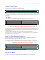
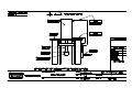
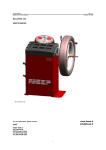
POLYTEST
Model 2 Test Sample
Injection Moulding
Apparatus
Copyright (C) 1998 all rights reserved world wide
• Revised Sept 2004 issue 2
RAY-RAN TEST EQUIPMENT LTD
Kelsey Close • Attleborough Fields Industrial Estate
Nuneaton • Warwickshire • CV11 6RS • United Kingdom
Tel: +44 (0)24 7634 2002 • Fax: +44 (0)24 7664 1670
E-Mail: [email protected]
Web Site: http://www.ray-ran.com
www.ray-ran.com
POLYMER TEST EQUIPMENT FOR WORLD WIDE QUALITY
CONTROL
1
Model 2 Test Sample Injection Moulding Apparatus
CONTENTS
Quick Reference Guide................................................................... 3
User Manual..................................................................................... 4
Description of the Machine ............................................................ 4
Caution During The Operation Of The Machine ........................... 4
Lifting & Installation........................................................................ 4
Electrical Power Supply ................................................................. 5
Tool Block........................................................................................ 5
Basic Tool Block Moulding Parameters........................................ 5
Special Tool Blocks ........................................................................ 5
Before Using & Storing The Machine............................................ 6
Compressed Air Supply ................................................................. 6
Tool Heater (Where Fitted) ............................................................. 6
Loading The Polymer...................................................................... 6
Operation Of The Machine ............................................................. 6
Changing The Piston & Cylinder Liner ......................................... 7
Temperature Control....................................................................... 8
Weights & Dimensions ................................................................... 8
Ram Assembly Diagram ................................................................. 9
Ray-Ran Products & Services...................................................... 10
2
Quick Reference Guide
Model 2 Test
Sample Injection
Moulding
Apparatus
Basic Moulding Technique
As with any moulding machine, moulding
parameters have to be established to suit
the particular material characteristics and
the section and size of the shape being
moulded. Most materials and shapes are
very different.
In our experience we have found that the
following guidelines are a useful starting
point.
Barrel Temperature
Generally, set the barrel temperature high
and reduce as necessary, especially if the
polymer burns or degrades.
Tool Temperature
For most polymers a tool temperatures of
up to 60 °C is sufficient. Increase the tool
temperature if the polymer freezes quickly.
Material Quality
Normally, fill the cylinder to the top. Using
the piston and air control, compress the
material to decrease the bulk and then refill
the cylinder. The polymer will melt more
efficiently. The tool block must be pushed
back during this operation to avoid polymer
freezing in the gate.
Time For Material To Melt
As a general rule, the material will slowly
fall from the die orifice when fully
plasticised. With the tool block pushed to
the back, purge out a small amount of
polymer then using the spatula knife
provided, trim the excess material from the
nozzle and quickly pull the tool block
forward and inject.
IMPORTANT
The special cam locking mechanism on the
tool block MUST be locked before injecting.
If it is not, the material will flash between
the plates and it will be impossible to unlock
the tool.
In the event of this happening, the tool
block will have to be removed from the
machine and disassembled. Under no
circumstances should the special cam
locking mechanism or tool plates be forced
as damage will occur to the insert faces.
Air Pressure
Most polymers, when fully molten, will inject
between 70 - 120 PSI. Some stiffer
materials will require a greater pressure. As
a general rule, start at around 70 PSI and
increase accordingly.
Continuous Moulding
Every time a sample is moulded, re-charge
the barrel, filling to the top. With the tool
block pushed back, compress the sample
using the piston and air to reduce the bulk.
Before every injection, purge slightly to
atmosphere and cut off the surplus polymer
before pulling the tool block back to the
front position and quickly injecting.
Special Larger Tool Block
And Larger Tool Inserts
With larger surface areas, it is
advantageous to lubricate the surfaces of
the plates with a mould release agent.
User Manual
3
Model 2 Test Sample Injection Moulding Apparatus
Please read this manual before attempting to operate the machine. All the information necessary to
successfully produce test samples has been included in this manual, and if used correctly the Test
Sample Injection Moulding Apparatus will provide you with an effective and trouble free system that
will serve you for many years. However, if after reading this manual you have any questions
concerning the instructions or recommendations regarding the use of the machine please contact RayRan for assistance.
Description Of The Machine
The Ray-Ran Model 2 Test Sample Injection Moulding Apparatus has been specifically designed to
produce a very wide variety of laboratory test samples such as colour plaques, tensile and impact test
pieces.
Polymer is loaded into the top of the liner which is heated to the required temperature to plasticise the
polymer. The piston is then pressed down into the top of the liner and extrudes the polymer through
the nozzle / orifice and into the tool sample insert. After the polymer has been allowed to set for a few
seconds, the tool block cam is released and the tool sample insert and top plate withdrawn. The
moulded test sample is removed, the orifice is cleaned of residual polymer, and the tool sample insert
together with the top plate are replaced and clamped in the tool block ready for the next sample to be
moulded.
Caution During The Operation Of The Machine
A heater band is fitted around the outside of the cylinder and, if specified, a cartridge heater unit is
fitted inside the tool block.
Although measures have been taken to avoid direct contact with the heater units, caution must still be
taken when operating the machine as inevitably surrounding areas will heat up during the operation of
the machine.
It is recommended that protective gloves should be used when filling, replacing or cleaning the
cylinder liner, withdrawing the tool sample insert and removing the moulded test sample.
The machine should be allowed to cool down before any maintenance or adjustments are carried out.
Lifting & Installation
The machine can be easily lifted by two people, each holding an upright support column and the base
of the machine. If using lifting equipment, place a lifting sling under the top cross member taking care
that the air hoses are well clear of the sling.The machine must be firmly bolted through the holes
provided in the base of the machine to a robust bench or stand.
The Pneumatic Ram will require fitting to the apparatus if, when unpacked, it is detached from the unit.
This is for packing convenience and the following fitting instructions should be followed.
(See assembly diagram page 9)
• Remove the 4 off M12 nuts from the fixing screws located in the top plate Ram mounting holes.
• Pull the Ram arm into the down position and remove the piston support boss and locking nut from
the thread.
• Place the Ram onto the top mounting plate and ensure the pipe connectors are facing the
connecting pipes and lever valve. Align the Ram with the top plate fixing holes and tighten the bolts
into the Ram with a 19mm A/F spanner.
• Connect the pipes to the Ram ensuring the longer pipe is fitted to the TOP air connector and the
shorter pipe to the BOTTOM air connector.
• Screw the locking nut onto the thread to its uppermost position and then fit the piston support boss.
Now tighten the locking nut down onto the Piston Support boss.
4
Model 2 Test Sample Injection Moulding Apparatus
Electrical Power Supply
The machine can be supplied in two versions as follows.
220-240 volts @ 50 Hz
110 volts @ 60 Hz
Please check the machine label to confirm the voltage. The machine power supply connection socket
incorporates an integral 10 amp fuse. The mains power supply plug must be earthed and fitted with a
13 amp fuse.
Tool Block
If the machine has been supplied with the standard tool block it will accept inserts of:-
Length
Width
Thickness
*
184 mm
44.45 mm
12.7 mm
Pease note these are not Maximum Moulding dimensions.
*
The tool sample insert must be positioned under the top plate and is locked in position by the bottom
plate being forced upwards by a unique cam device activated by turning the tool block handle in a
clockwise direction.
A variety of different tool sample inserts may be used but it is most important that
the thickness of 12.7 mm is always maintained. I.e. For a blank sample of say 4 mm, the blank or
mating plate must be 8.7 mm thickness.
Basic Tool Block Moulding Parameters
The basic tool block has been designed to accommodate most test samples required by all
International Standards. E.g. BS, ASTM, DIN, ISO, JIS, etc.
The system incorporates exchangeable inserts for each sample thus allowing low cost tooling.
*
The following maximum dimensions for moulding
Length
Width
Thickness
*
180 mm
38 mm
12.7 mm
The basic tool block incorporates a unique cam locking system.
Special Tool Blocks
Any size or type of tool can be supplied with the following maximum machine parameters.
5
Model 2 Test Sample Injection Moulding Apparatus
Length
Width
Thickness
200 mm
200 mm
25 mm
The above are maximum physical dimensions. The maximum size in volume of the sample is
governed by the maximum volume capacity of the cylinder.
Before Using & Storing The Machine
For protection during storage and transit the working parts of the machine have been treated with an
anti-rust solution. Please ensure that the machine surfaces are cleaned before use. If the machine is
not going to be used regularly, ensure that the cylinder liner bore, nozzle and the tool block
components are protected from deterioration.
Compressed Air Supply
The maximum operating pressure MUST NOT exceed 150 PSI (10.3 bars). It is important that an
inline air filter / regulator should be fitted to the air supply before it is connected to the
machine. The machine is supplied with its own secondary filter, regulator and pressure gauge.
Tool Heater (Where Fitted)
The tool block temperature required varies with the type of polymer being moulded, but generally it will
be much lower than the temperature setting required to plasticise the polymer in the liner. Determining
the ideal temperature for a given polymer can only be obtained by experiment. It is recommended to
start with a low temperature setting and gradually increase the temperature until the ideal moulding
conditions are obtained.
Loading The Polymer
Load the polymer into the bore using the filling hopper provided with the machine. Transfer the
polymer into the top of the cylinder bore pushing down on the handle. Periodically during the polymer
filling process, lower the piston to compress the polymer so that a full charge can be put into the
cylinder.
Operation of the Machine
This machine has been specifically designed to produce a wide variety of test samples such as colour
plaques, tensile and impact test samples. To produce such samples it has been found that the digital
tool heating package is required to obtain the best results.
The standard cam operated tool block has been designed to accept inserts for numerous different test
sample forms such as tensile bars, HDT bars, impact bars, colour plaques, etc.
For optimum performance an air supply of about 80-120 PSI is required.
When the air supply is connected to the machine the pneumatic cylinder ram is automatically pushed
back to its fully returned position, and in doing so, compresses the nozzle locking springs positioned
immediately below the pneumatic cylinder.
With the nozzle locking springs compressed, the nozzle is lifted clear of the tool block which is then
free to be moved forward into the moulding position and backwards to the unloading position.
6
Model 2 Test Sample Injection Moulding Apparatus
If the air supply is turned off ensure that the tool block is first in the unloading position. Set the tool
block and cylinder liner to the required temperatures and allow both to stabilise. It may be necessary
to adjust the temperature setting in order to determine the optimum settings for each polymer.
With a little experience, it becomes obvious whether the temperatures need to be raised or lowered for
each station. In almost every case the tool block temperature will need to be set a little lower than the
cylinder temperature. It is recommended that the temperatures are set a little lower than expected and
then gradually increase the temperature until the ideal conditions are obtained.
Position the tool block in the unloading position (pushed back). Position the mould insert and mating
top plate into the tool block and turn the locking handle to lock up the tool block. This is achieved by a
cam lock device (high mechanical advantage) connected to the locking / release handle, and therefore
hand tightening is sufficient.
Important - if the tool block is not locked up when moulding the polymer will be forced into the spaces
around the mould insert. It will then be extremely difficult to release the tool block, and it may prove
necessary to dismantle the complete tool block in order to free the tool insert. If the tool block cannot
be released with hand pressure remove the top plate. DO NOT hammer or lever the release handle.
Load the polymer into the top of the cylinder liner and leave to plasticise. If a full charge of polymer is
required, lower the piston (see below) a few times just to compress the polymer down into the cylinder
liner. This should only be a momentary load onto the polymer.
As soon as the polymer has plasticised, cut off any polymer which has already passed through the
nozzle and pull the tool block forward into the moulding position.
Operate the control valve which will direct compressed air into the top of the pneumatic cylinder. As
soon as the ram starts to come down the nozzle locking springs will be released and force the nozzle
into the tool block forming a sealed connection before the polymer is injected. As the ram continues to
come down, the piston will enter the cylinder liner, compress the polymer and inject it into the mould
insert in the tool block.
Wait a few seconds for the polymer to set and then release the control valve which will automatically
raise the ram and compress the nozzle locking springs, lifting the nozzle clear of the tool block so that
it can now be pushed back. Turn the release handle to unlock the tool block so that it can now be
pushed back. Turn the release handle to unlock the tool block, and withdraw the mould insert and top
plate. Press by hand the test sample out of the mould insert.
Ensure that any residual polymer around the orifice on the top plate of the tool block is removed so
that the polymer has free access into the mould insert.
The mould insert and top plate can be returned to the tool block and another test sample produced.
When you have finished moulding, always purge out any remaining polymer and clean the
components.
Changing The Piston & Cylinder Liner
Often there is a need to quickly change from one polymer to another or use another colour. This
machine enables both the piston and the cylinder liner to be changed in just a few seconds. By having
a spare cylinder liners and nozzles, one set can be used whilst cleaning the other at your leisure.
To remove the piston turn it anti-clockwise and pull down. By lowering the piston down, it can be
removed. Having done this the cylinder liner can also be removed.
The cylinder liner and polymer loading funnel are secured to the main cylinder with a fork locator to
facilitate easy removal of the cylinder liner without the need to have to contact the hot components.
Screw the fork handle into the fork locator and withdraw it. Place the fork locator into the holes
immediately above the ones it has just been taken out of. The fork locator now passes through the
upper part of the polymer loading funnel and cylinder liner. This assembly can now be lifted up clear of
the main cylinder and removed from the machine.
7
Model 2 Test Sample Injection Moulding Apparatus
Reverse the above procedure to replace both the cylinder liner and piston.
Temperature Control
The temperature controller for the cylinder heater band and the tool block heater cartridge (where
fitted) is a self tuning West N6100 instrument. The operating parameters of each instrument have
been factory set and should not require any further adjustment. For information, a manual of the
temperature controller is supplied with the machine.
After turning on the machine, the “SET” temperature which is the temperature you wish to operate the
machine at, appears in the lower of the two digital displays. To adjust the “SET” temperature press the
lower “Ú” key pad to reduce the “SET” temperature and the raise “Ù” key pad to increase the “SET”
temperature. Once the “SET” temperature has been selected the temperature controller will then
automatically adjust, monitor and stabilise the temperature of the cylinder liner and tool block to the
“SET” temperatures.
Weights & Dimensions
Net Weight
Gross Weight
Gross Width
Gross Depth
Gross Height
Cylinder Bore Diameter
Cylinder Length
55 kg
107 kg
60 cm
38 cm
126 cm
19.02 mm
180 mm
8
9
Ray-Ran Products & Services
Raw Material Evaluation
Code
RR/5MBA
RR/5SA
RR/5MPCA
RR/DGA
RR/BDA
RR/ADV
RR/VOY
RR/DIS
RR/MB
Product
Model 5MBA Melt Flow Indexer
Model 5SA Melt Flow Indexer
Model 5MPCA Melt Flow Indexer
3 Column Density Gradient Apparatus
Apparent Bulk Density Apparatus
Adventurer Balance (Readability 0.1mg) 110/260g Capacity
Voyager Balance (Readability 0.1mg) 62/410/100g Capacity
Discovery Balance (Readability 0.1mg) 110/310g Capacity
Moisture Balance (Readability 0.1%, 0.05%, 0.01%) 110/35/45g Cap
Sample Preparation
Code
RR/TSMP2
RR/HCP
RR/PCP
RR/NC
RR/CNC
RR/CNC 2
TSC + Standard
Product
Model 2 Test Sample Injection Moulding Apparatus
Hand Operated Test Sample Cutting Press
Pneumatically Operated Test Sample Cutting Press
Auto Cycle Test sample Notching Cutter
Test Sample Profile Cutter
Test Sample Profile Cutter - Larger
Test Sample Cutters
Sample Testing
Code
RR/HDV2
RR/HDV4
RR/HDV6
RR/TAA
RR/LTB
RR/ESC
RR/FSL
RR/FSHP
RR/IMT
RR/FWT
RR/FD
RR/ETT
RR/FT
RR/M
D202
B202
WS777
Product
2 Station HDT/Vicat Softening Point Apparatus
4 Station HDT/Vicat Softening Point Apparatus
6 Station HDT/Vicat Softening Point Apparatus
Thermal Ageing Apparatus
Low Temperature Brittleness Tester
Environmental Stress Cracking Apparatus
Unrestrained Linear Thermal Film Shrinkage Apparatus
Hot Plate Film Shrinkage Apparatus
Universal Pendulum Impact Tester
Falling Weight Impact Tester
Falling Dart Impact Tester
Advanced Elmendorf Tear Tester
Static And Dynamic Friction Tester
Universal Tensile Tester – Various Capacity
Digital Handheld Durometer
Analogue Handheld Durometer
Analogue & Digital Durometer Workstations
10