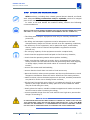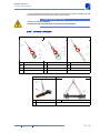
1
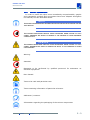
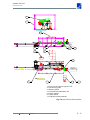
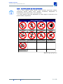
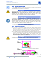
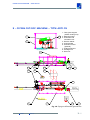
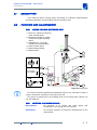
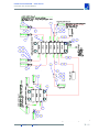
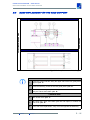
ORIGINAL INSTRUCTIONS
FLYING CUT-OFF MACHINE
TYPE A071 CS
Manufacturer
OFFICINE M.T.M. S.P.A.
Serial number
11M254
Building year
2011
experience your innovation
La riproduzione del presente manuale è vietata.
OFFICINE M.T.M. S.P.A. (di seguito denominata "MTM") si riserva il diritto di apportare in qualsiasi
momento le modifiche che ritenesse necessarie per il miglioramento della macchina.
This manual copying is forbidden.
OFFICINE M.T.M. S.P.A. (hereinafter referred to as "MTM") reserves the right of making the changes
needed for the improvement of the machine in any moment.
La reproduction de ce manuel est interdite.
OFFICINE M.T.M. S.p.A. (ci-dessous appelée "MTM") se réserve le droit d’apporter à tout moment les
modifications retenues comme nécessaires pour améliorer la machine.
La reproducción del presente manual está prohibida.
OFFICINE M.T.M. S.P.A. (en adelante "MTM") se reserva el derecho de aportar en cualquier momento las
modificaciones que considere necesarias para el mejoramiento de la máquina.
Воспроизводство настоящего руководства запрещено.
Фирма ЗАВОДЫ КОМПАНИИ М.Т.М. С.П.А. (именуемой в дальнейшем «МТМ») оставляет
за собой право внесения в любой момент изменений.
MANUAL DATA
Edition
01
Revision
07
Date
07/2012
MAIN TABLE OF CONTENTS
1 - MAIN TABLE OF CONTENTS
pag.
1-
MAIN TABLE OF CONTENTS . . . . . . . . . . . . . . . . . . . . . . . . . . . . . . . 1 - 1
2 - GENERAL SECTION . . . . . . . . . . . . . . . . . . . . . . . . . . . . . . . . . . . . . . 2 - 1
2.1
2.2
2.3
FOREWARD
INTRODUCTION . . . . . . . . . . . . . . . . . . . . . . . . . . . . . . . . . . . . . . . . . . . . . . . . . . . . . . . . . . . . . . . . . . 2 - 2
2.2.1
PRESENTATION OF THE MANUAL . . . . . . . . . . . . . . . . . . . . . . . . . . . . . . . . . . . . . . . . . . . . 2 - 2
2.2.2
COMPONENTS IDENTIFICATION . . . . . . . . . . . . . . . . . . . . . . . . . . . . . . . . . . . . . . . . . . . . . . 2 - 8
2.2.3
MANUFACTURER . . . . . . . . . . . . . . . . . . . . . . . . . . . . . . . . . . . . . . . . . . . . . . . . . . . . . . . . . . 2 - 8
2.2.4
COMPONENTS TECHNICAL FEATURES . . . . . . . . . . . . . . . . . . . . . . . . . . . . . . . . . . . . . . . . 2 - 8
GENERAL DESCRIPTIONS - TECHNICAL SPECIFICATIONS . . . . . . . . . . . . . . . . . . . . . . . . . . . . . 2 - 10
2.3.1
2.4
. . . . . . . . . . . . . . . . . . . . . . . . . . . . . . . . . . . . . . . . . . . . . . . . . . . . . . . . . . . . . . . . . . . . .2 - 1
TECHNICAL DATA . . . . . . . . . . . . . . . . . . . . . . . . . . . . . . . . . . . . . . . . . . . . . . . . . . . . . . . . . 2 - 10
MACHINE INSTALLATION . . . . . . . . . . . . . . . . . . . . . . . . . . . . . . . . . . . . . . . . . . . . . . . . . . . . . . . . . . 2 - 11
2.4.1
TRANSPORT AND HANDLING . . . . . . . . . . . . . . . . . . . . . . . . . . . . . . . . . . . . . . . . . . . . . . . . 2 - 11
2.4.2
LIFTING AND HANDLING RULES . . . . . . . . . . . . . . . . . . . . . . . . . . . . . . . . . . . . . . . . . . . . . .2 - 13
2.4.3
LIFTING TYPOLOGY . . . . . . . . . . . . . . . . . . . . . . . . . . . . . . . . . . . . . . . . . . . . . . . . . . . . . . . . 2 - 14
2.4.4 MACHINE UNPACKING . . . . . . . . . . . . . . . . . . . . . . . . . . . . . . . . . . . . . . . . . . . . . . . . . . . . . 2 - 16
2.4.5
MACHINE STORAGE BEFORE START-UP . . . . . . . . . . . . . . . . . . . . . . . . . . . . . . . . . . . . . 2 - 16
2.4.6 INSTALLATION AND CONNECTIONS . . . . . . . . . . . . . . . . . . . . . . . . . . . . . . . . . . . . . . . . . . 2 - 16
2.5
PERSONNEL TRAINING . . . . . . . . . . . . . . . . . . . . . . . . . . . . . . . . . . . . . . . . . . . . . . . . . . . . . . . . . . .2 - 17
2.6
MACHINE ADJUSTMENT . . . . . . . . . . . . . . . . . . . . . . . . . . . . . . . . . . . . . . . . . . . . . . . . . . . . . . . . . 2 - 18
2.7
2.6.1
SETTING-UP ADJUSTMENTS . . . . . . . . . . . . . . . . . . . . . . . . . . . . . . . . . . . . . . . . . . . . . . . 2 - 18
2.6.2
ADJUSTMENT DURING PRODUCTION . . . . . . . . . . . . . . . . . . . . . . . . . . . . . . . . . . . . . . . . 2 - 18
INSTRUCTIONS FOR MACHINE USE . . . . . . . . . . . . . . . . . . . . . . . . . . . . . . . . . . . . . . . . . . . . . . . 2 - 19
2.7.1
MACHINE USE . . . . . . . . . . . . . . . . . . . . . . . . . . . . . . . . . . . . . . . . . . . . . . . . . . . . . . . . . . . . 2 - 19
2.7.2
DESCRIPTION OF OPERATING MODES . . . . . . . . . . . . . . . . . . . . . . . . . . . . . . . . . . . . . . . 2 - 19
2.7.3
ACOUSTIC NOISE PRODUCED BY THE MACHINE . . . . . . . . . . . . . . . . . . . . . . . . . . . . . . 2 - 20
2.7.4
SAFETY PRECAUTIONS . . . . . . . . . . . . . . . . . . . . . . . . . . . . . . . . . . . . . . . . . . . . . . . . . . . . .2 - 21
2.7.5
SAFETY SIGNS ON THE MACHINES . . . . . . . . . . . . . . . . . . . . . . . . . . . . . . . . . . . . . . . . . . 2 - 22
2.7.6
SOFTWARE SAFETY PRECAUTIONS . . . . . . . . . . . . . . . . . . . . . . . . . . . . . . . . . . . . . . . . . 2 - 24
2.7.7
SAFETY PROTECTIONS . . . . . . . . . . . . . . . . . . . . . . . . . . . . . . . . . . . . . . . . . . . . . . . . . . . . 2 - 25
2.7.8
RESTRICTIONS OF USE . . . . . . . . . . . . . . . . . . . . . . . . . . . . . . . . . . . . . . . . . . . . . . . . . . . . 2 - 27
2.7.9
PREVENTION OF RISKS CAUSED BY MOBILE ELEMENTS . . . . . . . . . . . . . . . . . . . . . . 2 - 27
2.7.10 MACHINE SAFE OPERATION . . . . . . . . . . . . . . . . . . . . . . . . . . . . . . . . . . . . . . . . . . . . . . . . 2 - 27
2.7.11
11M254
PRECAUTIONS TO BE ADOPTED DURING THE OPERATION . . . . . . . . . . . . . . . . . . . . . 2 - 28
Edition 01
Revision 07
1-1
MAIN TABLE OF CONTENTS
pag.
2.8
MAINTENANCE REQUIREMENTS . . . . . . . . . . . . . . . . . . . . . . . . . . . . . . . . . . . . . . . . . . . . . . . . . . 2 - 29
2.8.1
SPECIAL MAINTENANCE . . . . . . . . . . . . . . . . . . . . . . . . . . . . . . . . . . . . . . . . . . . . . . . . . . . 2 - 29
2.9
TROUBLE SHOOTING . . . . . . . . . . . . . . . . . . . . . . . . . . . . . . . . . . . . . . . . . . . . . . . . . . . . . . . . . . . . 2 - 30
2.10
REPAIR AND REPLACEMENT OF PARTS . . . . . . . . . . . . . . . . . . . . . . . . . . . . . . . . . . . . . . . . . . . .2 - 31
2.11
MOVING THE MACHINE . . . . . . . . . . . . . . . . . . . . . . . . . . . . . . . . . . . . . . . . . . . . . . . . . . . . . . . . . . 2 - 32
2.11.1
SETTING THE MACHINE OUT OF SERVICE . . . . . . . . . . . . . . . . . . . . . . . . . . . . . . . . . . . . 2 - 32
2.11.2
DISASSEMBLE AND PACKAGE . . . . . . . . . . . . . . . . . . . . . . . . . . . . . . . . . . . . . . . . . . . . . . 2 - 32
2.11.3
TRANSPORT . . . . . . . . . . . . . . . . . . . . . . . . . . . . . . . . . . . . . . . . . . . . . . . . . . . . . . . . . . . . . 2 - 32
2.11.4
INSTALLATION . . . . . . . . . . . . . . . . . . . . . . . . . . . . . . . . . . . . . . . . . . . . . . . . . . . . . . . . . . . . 2 - 32
2.12
DEMOLITION OF THE MACHINE . . . . . . . . . . . . . . . . . . . . . . . . . . . . . . . . . . . . . . . . . . . . . . . . . . . 2 - 33
2.13
INTERVENTION REQUEST - TECHNICAL SERVICE . . . . . . . . . . . . . . . . . . . . . . . . . . . . . . . . . . . . 2 - 34
2.13.1
TECHNICAL SERVICE . . . . . . . . . . . . . . . . . . . . . . . . . . . . . . . . . . . . . . . . . . . . . . . . . . . . . . 2 - 35
2.14
WARRANTY . . . . . . . . . . . . . . . . . . . . . . . . . . . . . . . . . . . . . . . . . . . . . . . . . . . . . . . . . . . . . . . . . . . . 2 - 37
2.15
ORIGINAL SPARE PARTS . . . . . . . . . . . . . . . . . . . . . . . . . . . . . . . . . . . . . . . . . . . . . . . . . . . . . . . . 2 - 38
2.16
LIST OF TECHNICAL DOCUMENTS CONCERNING THIS MANUAL . . . . . . . . . . . . . . . . . . . . . . . 2 - 39
3 - FLYING CUT-OFF MACHINE – TYPE A071 CS . . . . . . . . . . . . . . . . . 3 - 1
3.1
DESCRIPTION . . . . . . . . . . . . . . . . . . . . . . . . . . . . . . . . . . . . . . . . . . . . . . . . . . . . . . . . . . . . . . . . . . . 3 - 2
3.2
FUNCTION AND ADJUSTMENTS . . . . . . . . . . . . . . . . . . . . . . . . . . . . . . . . . . . . . . . . . . . . . . . . . . . . 3 - 2
3.2.1
3.3
3.2.2
INFEED CENTRING UNIT . . . . . . . . . . . . . . . . . . . . . . . . . . . . . . . . . . . . . . . . . . . . . . . . . . . . 3 - 4
3.2.3
FLYING CUT-OFF MACHINE GEAR UNIT . . . . . . . . . . . . . . . . . . . . . . . . . . . . . . . . . . . . . . . 3 - 5
3.2.4
FLYING CUT-OFF CARRIAGE WITH CUTTING UNIT AND VICES . . . . . . . . . . . . . . . . . . . . 3 - 7
3.2.5
CUTTING UNIT . . . . . . . . . . . . . . . . . . . . . . . . . . . . . . . . . . . . . . . . . . . . . . . . . . . . . . . . . . . . . 3 - 8
3.2.6
PROTECTION TUNNEL (OPTIONAL) . . . . . . . . . . . . . . . . . . . . . . . . . . . . . . . . . . . . . . . . . . . 3 - 13
OPERATION . . . . . . . . . . . . . . . . . . . . . . . . . . . . . . . . . . . . . . . . . . . . . . . . . . . . . . . . . . . . . . . . . . . . 3 - 14
3.3.1
TOOL REPLACEMENT . . . . . . . . . . . . . . . . . . . . . . . . . . . . . . . . . . . . . . . . . . . . . . . . . . . . . . .3 - 15
3.4
BUSH REPLACEMENT ON THE RACK SUPPORT . . . . . . . . . . . . . . . . . . . . . . . . . . . . . . . . . . . . . .3 - 16
3.5
RACK REPLACEMENT . . . . . . . . . . . . . . . . . . . . . . . . . . . . . . . . . . . . . . . . . . . . . . . . . . . . . . . . . . . . . 3 - 17
3.6
INSTALLATION . . . . . . . . . . . . . . . . . . . . . . . . . . . . . . . . . . . . . . . . . . . . . . . . . . . . . . . . . . . . . . . . . . .3 - 18
3.7
3.8
11M254
FLYING CUT-OFF METERING UNIT . . . . . . . . . . . . . . . . . . . . . . . . . . . . . . . . . . . . . . . . . . . . 3 - 2
3.6.1
FOUNDATIONS . . . . . . . . . . . . . . . . . . . . . . . . . . . . . . . . . . . . . . . . . . . . . . . . . . . . . . . . . . . .3 - 18
3.6.2
ELECTRIC INSTALLATION . . . . . . . . . . . . . . . . . . . . . . . . . . . . . . . . . . . . . . . . . . . . . . . . . . . .3 - 18
LUBRICATION . . . . . . . . . . . . . . . . . . . . . . . . . . . . . . . . . . . . . . . . . . . . . . . . . . . . . . . . . . . . . . . . . . . .3 - 19
3.7.1
CUT-OFF MACHINE . . . . . . . . . . . . . . . . . . . . . . . . . . . . . . . . . . . . . . . . . . . . . . . . . . . . . . . . .3 - 19
3.7.2
METERING UNIT . . . . . . . . . . . . . . . . . . . . . . . . . . . . . . . . . . . . . . . . . . . . . . . . . . . . . . . . . . 3 - 22
WARNINGS . . . . . . . . . . . . . . . . . . . . . . . . . . . . . . . . . . . . . . . . . . . . . . . . . . . . . . . . . . . . . . . . . . . . 3 - 23
Edition 01
Revision 07
1-2
GENERAL SECTION
FOREWARD
2 - GENERAL SECTION
2.1
FOREWARD
This manual is a guide for the correct and safe use of the machine and for
its rational maintenance.
For this reason, we specify that the personnel operating the machine will
always be identified in this manual depending on the operations to be carried
out, as 2nd grade operator: skilled, authorised, equipped;
“informed” operator.
The constant compliance with the standards contained in this manual
ensures best performances, cost-effective operation, and machine long life
and avoids common causes of accidents, which may occur during work or
maintenance.
In designing and manufacturing the machine, the obligations imposed
to the operator of using, if necessary or expected, the individual protection
equipment (e.g. shoes, gloves, glasses, ear protectors, overalls, etc.) have
been taken into account.
This manual is an integral part of the machine and, therefore, the
personnel operating and maintaining the machine must be enabled
to easily make reference to it at any time.
The descriptions and pictures provided in this manual are not binding.
MTM reserves the right of making the changes that may be convenient for
improvement purposes without undertaking to update these documents.
For further clarifications, contact MTM offices, which are available for any
useful information.
11M254
Edition 01
Revision 07
2-1
GENERAL SECTION
INTRODUCTION
2.2
INTRODUCTION
2.2.1
PRESENTATION OF THE MANUAL
NOTE
ON RECEIVING THE MACHINE, BEFORE PROCEEDING TO ASSEMBLE OR MOVE, READ THE
USER GUIDE AND MAINTENANCE MANUALS CAREFULLY.
This manual contains instructions on how to handle, install, maintain,
operate and adjust the machine in question.
The manual is made up of various sections (in booklet form), each of
which covers a series of topics, subdivided into chapters and paragraphs
which deal with a precise application of the plant.
Section 2 - GENERAL SECTION contains a series of information regarding
the all plant, with particular regard to safety and handling.
The following sections, however, describe the individual machines of the
plant in detail.
Each section is divided up into topics, each topic describing a series of
operations in full.
The general table of contents constituent section 1, lists all the topics
covered in the whole manual.
The numbering of the pages of each section is independent and consists
in a progressive number preceded by the number of the section to which the
page belongs (e.g. 2-5 is page n° 5 of section 2).
This manual is intended for use by the personnel in charge of the
installation, use, maintenance and demolition of the machine, and is related
to the technical life of the machine subsequent to its manufacture and sale.
In the event the machine is subsequently transferred to a third party for
any reason (sale, free loan, or any other reason), the machine must be
handed over complete with all the documents.
The information contained in this manual is not intended as a substitute
for the knowledge and experience possessed by the customer using the
machine, who is fully responsible for the performance of the operations for
which the machine was purchased.
Before starting any operation on any unit, the person in question must
have at least read the whole manual and subsequently given greater
attention to the topic relating to the work to be performed.
This manual contains copyright information and cannot be furnished to
third parties, even in part, for any purpose and in any form without MTM's
prior written consent.
MTM hereby declares that the information contained in this manual is
consistent with the technical and safety specifications of the machine the
manual refers to.
A true copy of this manual is filed in the machine's technical folder which
is kept at MTM's offices.
MTM shall not recognize any documents which have not been produced,
released or distributed by MTM.
11M254
Edition 01
Revision 07
2-2
GENERAL SECTION
INTRODUCTION
2.2.1.1
GRAPHIC CONVENTIONS
In order to make the topics more immediately comprehensible, graphic
and typographic symbols and conventions have been adopted throughout
the manual, and are described below:
NOTE
THE NOTES CONTAIN IMPORTANT INFORMATION AND ARE HIGHLIGHTED ALONGSIDE THE TEXT
THEY REFER TO.
AT T E N T I O N
THE CAUTION INSTRUCTIONS INDICATE THOSE PROCEDURES WHERE FAILURE TO FULLY
COMPLY THEREWITH MAY RESULT IN DAMAGE TO THE MACHINE OR OTHER EQUIPMENT
CONNECTED TO IT.
DANGER
THE DANGER INSTRUCTIONS INDICATE THOSE PROCEDURES WHERE FAILURE TO FULLY
COMPLY THEREWITH MAY RESULT IN DAMAGE OR INJURY TO THE OPERATOR OR OTHER
PEOPLE NEARBY.
Warning
Attention.
Operation to be performed by qualified personnel for assistance on
electrical equipment.
Burn hazard.
Texts to be read with particular care.
Texts containing information of particular relevance.
Addresses / contacts.
Information regarding the packaging of the various components.
11M254
Edition 01
Revision 07
2-3
GENERAL SECTION
INTRODUCTION
Information on transportation by truck.
Information on transportation by ship.
Information on transport and handling.
Danger suspended load.
Information regarding adjustment procedures.
Information regarding acoustic noise.
Ear protection is compulsory.
Body protection is compulsory.
Machine downtime.
Information regarding the machine fixing to the floor.
Lubricant loading.
Information regarding greasing / lubrication.
Pressure greasing.
Manual greaasing.
11M254
Edition 01
Revision 07
2-4
GENERAL SECTION
INTRODUCTION
COUNTER CLOCK WISE rotation of the horizontal screw.
CCW
CW
CLOCK WISE rotation of the horizontal screw.
.
CW
CLOCK WISE rotation of the vertical screw.
.
CCW
COUNTER CLOCK WISE rotation of the vertical screw.
CW
CLOCK WISE rotation of the component.
CCW
COUNTER CLOCK WISE rotation of the component.
Vertical movement of the component.
Horizontal movement of the component.
2.2.1.2
Wording
in italics
11M254
TYPOGRAPHIC CONVENTIONS
Used to indicate reference to figures, chapters or topics other than the
current ones.
Edition 01
Revision 07
2-5
GENERAL SECTION
INTRODUCTION
2.2.1.3
UNITS OF MEASUREMENT – INTERNATIONAL SYSTEM (SI)
Basic SI units
Length
meter
m
Mass
kilogram
kg
Time
second
s
Electric current
ampere
A
Thermodynamic temperature
kelvin
K
Angular measure
radian
rad
SI derived units
11M254
Strength
newton
N
Pressure
pascal
Pa
Energy
joule
J
Power
watt
W
Voltage
volt
V
Frequency
hertz
Hz
Capacitance
farad
F
Electrical resistance
ohm
Ω
Edition 01
Revision 07
2-6
GENERAL SECTION
INTRODUCTION
SI prefixes
11M254
Edition 01
tera
T
1012
1 000 000 000 000
giga
G
109
1 000 000 000
mega
M
106
1 000 000
kilo
k
103
1 000
hecto
h
102
100
deca
da
101
10
deci
d
10-1
0.1
centi
c
10-2
0.01
milli
m
10-3
0.001
micro
µ
10-6
0.000 001
nano
n
10-9
0.000 000 001
pico
p
10-12
0.000 000 000 001
Revision 07
2-7
GENERAL SECTION
INTRODUCTION
2.2.2
COMPONENTS IDENTIFICATION
The machine model is shown on the nameplate located on the upper right
corner of the Main Electric Cabinet. It bears the following data:
MANUFACTURER: OFFICINE M.T.M. S.P.A.
MACHINE MODEL: FLYING CUT-OFF MACHINE
TYPE A071 CS
SERIAL NUMBER:
11M254
YEAR OF CONSTRUCTION: 2011
2.2.3
MANUFACTURER
The machine described in this user’s manual and the models deriving from
it are manufactured and sold by:
Officine M.T.M. S.P.A.
via Palladio 36 | 30038 Spinea Venezia | Italy
tel +39 041 5089611 | fax +39 041 999611
www.mtmtubemills.com
2.2.4
COMPONENTS TECHNICAL FEATURES
The machine manufactured by MTM consists of:
• Flying cut-off machine type A71 CS
• Cut-off entry guide
• Metering wheel
• Pneumatic and lubrication unit
• Electric cabinet
• Control board
11M254
Edition 01
Revision 07
2-8
GENERAL SECTION
INTRODUCTION
1
7
5
1
7
4
5
3
2
2
1
7
6
3
1- Flying cut-off machine type A71 CS
2- Cut-off entry guide
3- Metering wheel
4- Pneumatic and lubrication unit
5- Electric cabinet
6- Control board
7- Protection tunnel (optional)
Fig. 2-A General view of the machine
11M254
Edition 01
Revision 07
2-9
GENERAL SECTION
GENERAL DESCRIPTIONS - TECHNICAL SPECIFICATIONS
2.3
GENERAL DESCRIPTIONS - TECHNICAL SPECIFICATIONS
2.3.1
TECHNICAL DATA
2.3.1.1
MATERIAL SPECIFICATIONS
• Material to be processed:
Carbon steel
• Max tensile strength:
550 N/mm²
• Type of production:
Round, Square and Rectangular tube
• Tube diameter:
MIN ¾” - MAX 3”
• Thickness:
MIN .026” - MAX .156”
• Final tube Length:
MIN 4.0 m - MAX 8.0 m
2.3.1.2
MAIN TECHNICAL FEATURES
• Mechanically predisposed speed: MAX 150 m/min
11M254
• Cutting process:
Cold Saw
• Cutting tollerance:
± 1.5 mm
• Cutting head movement:
Electro-mechanical
• Tube clamping:
Mechanical, pneumatically actuated
• Saw drive:
Electric motor with variable speed
converter
• Saw carriage drive:
Elecric motor through pinion and rack
• Cuts per minute:
MAX 25/min on 6 meters lenght tubes
• Direction of operation:
Right to Left
• Mill pass line from floor:
1000 mm
• Voltage:
480 V – 60 Hz
Edition 01
Revision 07
2-10
GENERAL SECTION
MACHINE INSTALLATION
2.4
MACHINE INSTALLATION
2.4.1
TRANSPORT AND HANDLING
DANGER
WARNING! SKILLED PERSONNEL TRAINED FOR THIS TYPE OF OPERATIONS MUST CARRY
OUT HANDLING AND LIFTING OPERATIONS.
In order to facilitate transport operations and depending on requirements,
MTM transports its machines either assembled or disassembled into their
parts.
All the machine mechanical parts are protected using protective paints
and/or protective oil before shipping them.
Instead, electrical parts are protected with plastic films, and bags
containing dehydrating salts are put inside.
The load is then fastened by means of ropes and belts.
AT T E N T I O N
MAKE SURE THAT, WHERE THE BELTS/ROPES TOUCH THE MACHINE, SUITABLE
PROTECTIONS OF THE CONTACT SURFACE ARE PLACED IN ORDER NOT TO DAMAGE IT.
The plant accessories, regardless of the means of transport used, are
generally packed in wooden cases, lined with shock-resistant blister
polyethylene sheets.
In case of transport by sea, dehydrating salt bags will also be used.
In addition, MTM makes custom-made packaging on customer’s requests
or due to special requirements (size or material fragility).
Machines are loaded in bulk on both boxes and containers.
After the arrival at the customer’s premises, the machines and cases will
have to be handled very carefully using equipment having a carrying
capacity adequate to the weight to be lifted and handled both indoor and
outdoor.
If the anchoring instructions are not complied with, there is the risk that
the machine or the case overturns or falls (see lifting diagrams in the
following chapter).
The described solutions also apply in case the machine or parts of it are
lifted or handled by the customer or in case of future movements.
For the cases, the standard transport modalities apply.
Two different transport solutions can be adopted to deliver the machine to
the user, namely:
a) Truck
The machine is loaded on low-bed or standard trucks always covered by
tarpaulin, which must ensure the protection of the load against atmospheric
agents.
We recommend to always check the covering tarpaulin integrity.
11M254
Edition 01
Revision 07
2-11
GENERAL SECTION
MACHINE INSTALLATION
b) Ship
The machine is loaded on board by 40’ or 20’ open-top containers or
wooden boxes coated with tarpaper and lined with nylon.
We recommend to always check the covering tarpaulin integrity.
AT T E N T I O N
TRANSPORT TEMPERATURE: FROM -25°C TO +55°C, UP TO + 70°C FOR NOT MORE THAN
24H.
11M254
Edition 01
Revision 07
2-12
GENERAL SECTION
MACHINE INSTALLATION
2.4.2
LIFTING AND HANDLING RULES
MTM machines, including their related general electric boards, are fitted
with adequate lifting connections and/or eyebolts, which are integral
part of the machine and designed according to its weight.
In order to lift and handle the machine safely, observe the following
recommendations:
DANGER
DO NOT STAND OR PASS UNDER SUSPENDED LOADS AND IN THE AREAS WHERE SAID LOADS
ARE LIKELY TO FALL, EVEN WHEN TRANSLATION MOVEMENTS ARE NOT CARRIED OUT;
• The lifting and transport equipment must only be used by authorised
personnel;
• the lifting and transport equipment must be adequate to the load
characteristics, shape and volume as well as to the operating conditions;
• the efficiency of the equipment, and in particular ropes, metal cables,
chains, hooks must be checked and possible irregularities must be
pointed out;
• the carrying capacity of the equipment must be complied with;
• check that the equipment and load path is free from any obstacle;
• check that the operating station allows perfect visibility;
• make sure that the loads are correctly slung, preventing the ropes from
sliding on both the load and the hook and preventing them from slipping
on sharp edges; bends with small radius of curvature and multiple
torsion;
• ensure the means and load stability;
• ensure that the hook does not stick to fixed structures;
• place the hooks in a barycentric position and do not pull slantwise to avoid
dangerous oscillations when the load is lifted from the resting surface;
• make sure that, where the belts/ropes touch the load, suitable protections
are placed in order not to damage these surfaces;
• lift the load, first as high as to check if it is balanced, then lift it at regular
speed to the height needed to safely pass over all the obstacles which
may be found along the route;
• slowly place the load on suitable resistant supports and make sure that it
cannot overturn after loosening the slings;
• remove possible slings from the hook and lift it as high as to prevent the
danger of knocking it.
DANGER
IF THESE OPERATIONS HAVE NOT BEEN CORRECTLY CARRIED OUT, THERE IS STILL THE RISK
MTM
DECLINES ANY RESPONSIBILITY. IT IS RECOMMENDED THAT SKILLED PERSONNEL TRAINED
FOR THIS TYPE OF OPERATIONS CARRY OUT HANDLING AND LIFTING OPERATIONS.
THAT THE MACHINE, CASES AND ELECTRIC BOARD OVERTURN OR FALL. IN ANY CASE,
11M254
Edition 01
Revision 07
2-13
GENERAL SECTION
MACHINE INSTALLATION
Some drawings showing the anchoring points of the lifting equipment and
the weights of each machine are given here below.
REMAINING RISK
- CHECK ALL LIFTING EQUIPMENT;
- ENSURE THE HOOKS ARE SUITABLE TO THE CAPACITY AND EFFICIENT.
2.4.3
LIFTING TYPOLOGY
Fig. 2-B TYPE 1
Fig. 2-C TYPE 2
Fig. 2-D TYPE 3
A CABLE
A CABLE
A CABLE
B HOOK
B HOOK
B HOOK
C ROLLER
C ROLLER
C BELT
D EYEBOLT
D HANGER
Fig. 2-E TYPE 4
A CABLE
Fig. 2-F TYPE 5
A
LIFTING DEVICE
B TUBE
11M254
Edition 01
Revision 07
2-14
GENERAL SECTION
MACHINE INSTALLATION
TECHNICAL DATA
MACHINE MODEL
CUT-OFF MACHINE
OVERHEAD TRAVELING CRANE
OR CRANE
LIFTING TYPOLOGY
TYPE
2/5
WEIGHT
~
Kg
7000
TECHNICAL DATA
MACHINE MODEL
ELECTRIC CABINET
OVERHEAD TRAVELING CRANE
OR CRANE
LIFTING TYPOLOGY
TYPE
1
WEIGHT
~
Kg
800
TECHNICAL DATA
MACHINE MODEL
CONTROL BOARD
OVERHEAD TRAVELING CRANE
OR CRANE
LIFTING TYPOLOGY
TYPE
2
WEIGHT
~
11M254
Edition 01
Revision 07
190
Kg
2-15
GENERAL SECTION
MACHINE INSTALLATION
As for the lifting and transport of the cases containing accessories or parts
or the plant, the same rules listed at the beginning of this chapter apply.
DANGER
SKILLED PERSONNEL TRAINED FOR THIS TYPE OF OPERATIONS MUST CARRY OUT HANDLING
AND LIFTING OPERATIONS.
2.4.4 MACHINE UNPACKING
The machine parts and the cases containing accessories or plant parts
must be unpacked with care according to good technique standards,
avoiding damages and faults that may compromise the machine good
operation.
DANGER
THEREFORE, WE RECOMMEND THAT SKILLED PERSONNEL TRAINED FOR THIS TYPE OF
OPERATIONS CARRY OUT UNPACKING OPERATIONS.
MTM is not responsible for problems in installing the machine caused by
damages occurred during the transport, handling and unpacking of the
machine and of all its parts.
2.4.5
MACHINE STORAGE BEFORE START-UP
When arriving by the customer and before start-up, the machine must be
stored by the MTM authorised technical personnel in premises ensuring its
protection from bad weather, from the atmospheric agents and from any
cause or external agent which may damage it (e.g. chemical agents, dust,
shocks, etc.). In particular:
AT T E N T I O N
STORAGE TEMPERATURE: FROM -25°C TO +55°C, UP TO 70°C FOR NOT MORE THAN 24H.
2.4.6 INSTALLATION AND CONNECTIONS
Before sending the machine, MTM will send the layout showing the
arrangement of the bases and the connections to the distribution networks
for power requirements (electric power, water, air, oil, etc.).
The installation, connections, and testing must only be carried out under
the control of MTM TECHNICAL ASSISTANCE PERSONNEL or, alternatively,
according to the previous agreements with MTM and to its authorisations.
The great technological content of this machine does not allow the user to
intervene in the above-mentioned operations, excepted that in the presence
of MTM AUTHORIZED ENGINEERS or, alternatively, according to the
previous agreements with MTM and to its authorisations.
11M254
Edition 01
Revision 07
2-16
GENERAL SECTION
PERSONNEL TRAINING
2.5
PERSONNEL TRAINING
During the machine installation, the personnel selected by the customer
will be trained in the machine use.
We recommend to select the skilled personnel in advance taking into
account that, in relation to the its great technological level, the machine
must be operated by skilled personnel having a great experience in
using similar machines.
The personnel training ends when the plant is started, unless otherwise
agreed; in this case reference will be made to the order confirmation
subscribed by both parties. This phase is defined by the “starting report”
where the names of the people trained in the machine use will be listed.
11M254
Edition 01
Revision 07
2-17
GENERAL SECTION
MACHINE ADJUSTMENT
2.6
MACHINE ADJUSTMENT
For machine adjustments are meant all the adjustments to be carried out
to obtain the maximum machine operating performance.
They are subdivided into:
• Setting-up adjustments
• Adjustment during production
2.6.1
SETTING-UP ADJUSTMENTS
They are the ones made during machine testing and installation or in case
of operation restoring after a period of stop.
The machine setting-up adjustment is only carried out by MTM personnel
or, alternatively, according to the previous agreements with MTM and to its
authorisations.
It is carried out in collaboration with the personnel operating the machine,
which will provide the data concerning the production specifications to MTM
engineers.
2.6.2
ADJUSTMENT DURING PRODUCTION
They are carried out and repeated by the trained personnel according to
the requirements resulting from the machine normal use.
As for the latter ones, make reference to the technical forms concerning
each machine.
DANGER
SKILLED PERSONNEL TRAINED IN THIS TYPE OF OPERATIONS ONLY MUST CARRY OUT
ADJUSTMENT OPERATIONS.
11M254
Edition 01
Revision 07
2-18
GENERAL SECTION
INSTRUCTIONS FOR MACHINE USE
2.7
INSTRUCTIONS FOR MACHINE USE
All the above operations are controlled through sophisticated electronic
equipment consisting of electric panels, control boards, monitoring systems
and control boxes.
Operators trained by MTM engineers (see chapter 2.5 PERSONNEL
TRAINING (pag. 2-17)) control all the operating modes above described.
2.7.1
MACHINE USE
Personnel trained in its use can only operate the machine.
The machine control operations are described in detail in the enclosed
User’s manual for the supervisor.
The technical forms concerning the machines making up the line are
included in the present manual.
2.7.2
DESCRIPTION OF OPERATING MODES
The plant in question has two operating modes: manual mode and
automatic mode.
2.7.2.1
MANUAL MODE
The operator may decide to work in manual mode for the following
reasons:
• fine tuning of the machine;
• resolution of any problems when operating in automatic cycle.
2.7.2.2
AUTOMATIC MODE
The machine must always work in automatic mode.
The operator has only to check the potential problems (see the video
pages).
11M254
Edition 01
Revision 07
2-19
GENERAL SECTION
INSTRUCTIONS FOR MACHINE USE
2.7.3
ACOUSTIC NOISE PRODUCED BY THE MACHINE
During design the lowering of the noise threshold has been especially
evaluated. However, the requirements deriving from the machine normal
operation do not allow its complete soundproofing by suitable acoustic
insulating materials.
Therefore, the operator will have to wear ear protectors.
The system noise changes as the test position changes.
Measurements carried out with the machine operating without tube in
production differ from the ones carried out with the tube on line.
With the tube in production the noise is very high and the operators will
have to wear ear protectors.
The level of acoustic pressure hereinafter described has been detected on
a machine identical to the one object of this manual, under normal operating
conditions and during the production of steel tubes and profiles at the speed
of 130 m/min.
For measuring the real level of acoustic pressure, a noise meter mod.
DELTA OHM HD8701 having the following characteristics has been used:
• Measure range (Autorange)
40÷130 dB
• Frequency Response
Weighted mean A
Being the machine very long, and the working position variables, The
acoustic pressure level has been measured at 1 m from the surface of the
machine and at 1.60 m height above the ground near the working areas
listed below.
The actual measurement of the acoustic pressure level, carried out during
production, is the following:
• Cut-off machine area
11M254
Edition 01
Revision 07
< 80 dB
2-20
GENERAL SECTION
INSTRUCTIONS FOR MACHINE USE
2.7.4
SAFETY PRECAUTIONS
AT T E N T I O N
THE MANUFACTURER IS NOT RESPONSIBLE FOR DAMAGES TO PEOPLE OR OBJECTS
RESULTING FROM NON-COMPLIANCE WITH THE SAFETY STANDARDS. SKILLED PERSONNEL
EXPERIENCED IN THE USE OF SIMILAR MACHINES MUST OPERATE THE MACHINE.
The machine can be considered safe if it has been designed to be used,
adjusted, maintained, dismantled and eliminated in its expected use
conditions without causing injuries or damages to health.
In order to achieve this aim, MTM has adopted the following measures:
a) Reduction of risks starting from design.
During design, the expected use, space and time restrictions have been
taken into consideration.
The dangers have been identified and all the dangerous situations have
been evaluated considering:
• the different aspects of the operator-machine relation
• the possible machine states
• the reasonable and expected use
b) Protection measures.
On the basis of the analysis in point a), protections have been studied
and designed:
• A - protections from transmission mobile components;
• B - protections from mobile components involved in working.
In both cases, protection consists of fixed, mobile and electronic devices.
The machine is fitted with devices for the protection of the operator from
the risks deriving from noise and vibrations.
c) Use information.
The machine is fitted with danger and warning signs and operating
instructions.
d) Personal means of protection.
MTM has taken into account that the operators controlling the machine
are always equipped with the following personal protection devices:
helmet, ear protectors, glasses, accident-preventing shoes, overall.
e) The indication of some written procedure the users must apply.
11M254
Edition 01
Revision 07
2-21
GENERAL SECTION
INSTRUCTIONS FOR MACHINE USE
2.7.5
SAFETY SIGNS ON THE MACHINES
For a more efficacy safety action, some accident prevention plates,
concerning specific safety rules, danger conditions, obligations or
prohibitions, have been fixed on the machines.
In some specific case the application of these signs is referred to the
present safety regulations.
SIGNS GIVING ORDERS
Do not smoke and do
not use flames
Entry forbidden to
pedestrians
Do not use water to
extinguish the flames
Entry forbidden to
unauthorised
persons
Do not smoke
Non drinkable water
Entry forbidden to
trucks and forklifts
Do not touch
Do not remove
protection devices
Fig. 2-G Signs giving orders
11M254
Edition 01
Revision 07
2-22
GENERAL SECTION
INSTRUCTIONS FOR MACHINE USE
(1) In absence of a specific high temperature control.
Fig. 2-H Warning signs
11M254
Edition 01
Revision 07
2-23
GENERAL SECTION
INSTRUCTIONS FOR MACHINE USE
COMPULSORY SIGNS
Eye protection is
compulsory
Breathing protection
is compulsory
Face protection is
compulsory
Safety gloves are
compulsory
Safety footwear is
compulsory
Warning (with
possible additional
sign)
Safety helmets are
compulsory
Ear protection is
compulsory
Body protection is
compulsory
Individual protection
against falls is
compulsory
Compulsory path for
pedestrian
Lifting point
Fig. 2-I Compulsory signs
2.7.6
SOFTWARE SAFETY PRECAUTIONS
Software installed on personal computers of the control boards is tested
and controlled by MTM before delivery, in order to avoid presence of any
“virus”.
MTM is not responsible for any virus present in the system and
recommends that the customer provides its computer systems with a
suitable antivirus program.
The antivirus program will have to be installed by a skilled engineer and,
to be considered reliable, it will have to be continuously updated.
Back up copies of the operative programs is supplied together with the
electric documentation.
11M254
Edition 01
Revision 07
2-24
GENERAL SECTION
INSTRUCTIONS FOR MACHINE USE
2.7.7
SAFETY PROTECTIONS
Each MTM machine is fitted with protections in order to avoid injuries
and damages to the health of the operators.
DANGER
PROTECTIONS ARE DESIGNED ACCORDING TO THE STANDARDS LISTED IN PARAGRAPH
“FOREWORD”.
AS FOR PERIMETRAL PROTECTIONS MTM HAS IDENTIFIED, DURING DESIGN PHASE,
POSSIBLE RISKS AND DANGERS THAT MAY OCCUR TO USERS IN CASE OF NONINSTALLATION, AND HAS INFORMED CUSTOMER OF THOSE OCCURRENCES.
AT T E N T I O N
IN DESIGNING AND MANUFACTURING THE PROTECTIONS DESCRIBED BELOW, THE
OBLIGATIONS IMPOSED TO THE OPERATOR, IF NECESSARY OR EXPECTED, THE
INDIVIDUAL PROTECTION EQUIPMENT (E.G. SHOES, GLOVES, GLASSES, EAR PROTECTORS,
OVERALLS, HELMET, ETC.) HAVE BEEN TAKEN INTO ACCOUNT (E.G. SAFETY SHOES,
GLOVES, EYEGLASSES, HEADSETS, OVERALLS, HELMET, ETC.)
In more details, the machine must be equipped with:
2.7.7.1
a-
FLYING CUT-OFF MACHINE
A device for immediate stopping of the line (named “Pipe jamming
device”) is located at the cropper entry point. This device consists of a
steel ring in which the pipe to be cut slides, and which is activated when
the pipe abandons the normal sliding location, and touches the ring.
b- The cropper must also be equipped with a mechanical protection named
“tunnel” (constructed by the customer), which can be opened to prevent
access to the cutting operation zone. The protection must have
interlocking devices which are tripped when the protection is opened,
thus preventing the system from operating.
DANGER
IF PROTECTION IS NOT PROPERLY CLOSED THE MACHINE MUST NOT BE OPERATED.
1
1
1- Protection tunnel (optional)
Fig. 2-J Protection tunnel
11M254
Edition 01
Revision 07
2-25
GENERAL SECTION
INSTRUCTIONS FOR MACHINE USE
2.7.7.2
ADDITIONAL PROTECTIONS
In addition to the above protections, MTM machines are equipped with:
a-
Safety devices.
Fast stop push buttons installed on the control boards.
b- Warning signs and notices located on the machine sides.
DANGER
THE OPERATOR IS OBLIGED TO USE THE INDIVIDUAL PROTECTION DEVICES.
11M254
Edition 01
Revision 07
2-26
GENERAL SECTION
INSTRUCTIONS FOR MACHINE USE
2.7.8
RESTRICTIONS OF USE
This machine must only be used in compliance with the working schemes
envisaged by the Manufacturer and described in detail by this manual and
its enclosures.
According to the machine operating site as per order confirmation, the
climate parameters to be complied with are the following:
TEMPERATURE:
AMBIENT AIR UNDER OPERATING CONDITIONS FROM +5° C TO +40°C.
AVERAGE AMBIENT AIR TEMPERATURE NOT EXCEEDING +35°C FOR A
24H PERIOD.
HUMIDITY
≤ 80% WITHOUT CONDENSE
HEIGHT
≤ 1000 M A.S.L.
AT T E N T I O N
IF THE MACHINE SHOULD BE MOVED FROM THE ORIGINAL SITE WHERE IT HAS BEEN
AND TESTED BY MTM AUTHORISED TECHNICAL PERSONNEL, CLIMATE
PARAMETERS MAY CHANGE CAUSING MALFUNCTIONING.
INSTALLED
2.7.9
PREVENTION OF RISKS CAUSED BY MOBILE ELEMENTS
When designing its machine, MTM pays special care to the prevention of
risks that may arise from their use.
Prevention is considered by MTM with special care, as its machines are
NOT mass-produced.
MTM machines are projected, designed and manufactured according to
the customer’s technical specifications.
That is the reason why MTM each time projects and installs special risk
protection.Besides MTM has projected the protections in accordance with
the standards listed in paragraph 2.1 FOREWARD (pag. 2-1).
2.7.10 MACHINE SAFE OPERATION
During the machine design phase, MTM
dangers the operator can be subject to.
has checked the risks and
On the basis of the carried out analysis, devices, signs, procedures and
any other measure considered necessary for safety purposes have been
provided.
In its evaluation, MTM has also considered that the operator, in
compliance with the general safety standards, uses the following individual
protection devices: overall, accident preventing shoes, glasses, ear
protectors, helmet, gloves.
11M254
Edition 01
Revision 07
2-27
GENERAL SECTION
INSTRUCTIONS FOR MACHINE USE
2.7.11
PRECAUTIONS TO BE ADOPTED DURING THE OPERATION
2.7.11.1
RECOMMENDED PROCEDURE
DANGER
THE PHYSICAL BARRIERS ARRANGED ON THE MACHINE LAYOUT MUST NEVER BE REMOVED
DURING THE MACHINE OPERATION.
Should they be removed due to technical problems, all the possible
measures able to:
• highlight the danger
we suggest using danger signs placed on the control board.
• minimise the resulting danger.
It is advisable to stop the machine by removing the power keys.
The access means to the production area, adjustment and
maintenance points are designed and realised to ensure the safety
of operators carrying out these operations; anyway operators must
always be previously trained.
Those operations must always be carried out with the machine
stopped.
Barriers must be re-fitted in their normal position as soon as the
reasons making necessary their temporary removal are expired.
DANGER
ACCESS TO THE MACHINE DURING ITS OPERATION IS FORBIDDEN, EXCEPT IN THE SUITABLY
ARRANGED AREAS, AND HOWEVER IT IS RESERVED TO THE TRAINED AND SKILLED
PERSONNEL ONLY.
2.7.11.2
DESCRIPTION OF THE PROTECTION DEVICES INSTALLED
As for the protection devices installed, make reference to the specific
technical forms of the single machines.
11M254
Edition 01
Revision 07
2-28
GENERAL SECTION
MAINTENANCE REQUIREMENTS
2.8
MAINTENANCE REQUIREMENTS
DANGER
ALL THE MACHINE ROUTINE AND SPECIAL MAINTENANCE OPERATIONS DESCRIBED BELOW
MUST BE CARRIED OUT WITH THE MACHINE STOPPED AND DISCONNECTED.
For the operations relevant to the machine maintenance, refer to the
specific technical forms of each machine and to the specific documentation
relevant for each part, equipment and accessory supplied with the machine.
At the end of the maintenance operations and before starting the
machine, it is mandatory to check that all the safety devices installed by
MTM or by the customer have been restored and that the general safety
standards are complied with.
2.8.1
SPECIAL MAINTENANCE
Special maintenance operations can be carried out by both MTM and
customer personnel.
If these operations are carried out by the customer, at the end of the
maintenance operations and, in any case, before starting the machine, it is
mandatory to check that all the safety devices installed by MTM have been
restored and that the general safety standards are complied with.
11M254
Edition 01
Revision 07
2-29
GENERAL SECTION
TROUBLE SHOOTING
2.9
TROUBLE SHOOTING
The electronic equipment fitted on the machines produced by MTM
includes a Fault-finding Diagnostic System.
This diagnostic system is described to the personnel in charge during the
machine installation and personnel training phase. At the end of the machine
testing phase, the personnel in charge is able to carry out all fault-finding
diagnostic operations.
Beside the above, a user manual for video operation, inclusive of Faultfinding System, is supplied together with the electrical documentation.
If, at the end of these operations, the problem is not solved, the customer
shall contact MTM by sending the enclosed “TECHNICAL SERVICE” (see
chapter 2.13.1 TECHNICAL SERVICE) form giving a brief and clear description
of the malfunctioning or trouble.
11M254
Edition 01
Revision 07
2-30
GENERAL SECTION
REPAIR AND REPLACEMENT OF PARTS
2.10
REPAIR AND REPLACEMENT OF PARTS
The repair and replacement of the parts will be agreed upon case by case
with the MTM offices.
For this purpose, refer to the chapters 2.13 INTERVENTION REQUEST TECHNICAL SERVICE (pag. 2-34) and 2.14 WARRANTY (pag. 2-37).
11M254
Edition 01
Revision 07
2-31
GENERAL SECTION
MOVING THE MACHINE
2.11
MOVING THE MACHINE
2.11.1
SETTING THE MACHINE OUT OF SERVICE
Before moving the machine, the user should have removed all the
material being processed on the line.
After this operation, he will disconnect the machine from all the
distribution networks (electric power, water, air, oil, etc.).
Due to the high technological content of the machine, all the above
operations must be carried out by skilled personnel trained for this purpose.
2.11.2
DISASSEMBLE AND PACKAGE
Before being moved, the machine must be disassembled and packed, in
order to avoid damages that may compromise its regular operation to the
detriment of the personnel safety.
Disassembly and packing operations must be carried out by skilled
personnel trained for this purpose.
In particular, for packing modalities, make reference to the chapter 2.4.1
TRANSPORT AND HANDLING (pag. 2-11).
2.11.3
TRANSPORT
Transport operations must be carried out by skilled and suitably trained
personnel.
For modalities, make reference to the chapter 2.4.1 TRANSPORT AND
HANDLING (pag. 2-11).
2.11.4
INSTALLATION
Installation operations must be carried out by skilled and suitably-trained
personnel.
When the machine is moved from the original seat where MTM authorised
technical personnel had installed and tested it, any form of warranty and
responsibility of the Manufacturer fails.
If the user requests the intervention of MTM authorised technical
personnel for the machine installation in the new site, the warranty validity
will be agreed with MTM and will start from the commissioning and testing
report date.
11M254
Edition 01
Revision 07
2-32
GENERAL SECTION
DEMOLITION OF THE MACHINE
2.12
DEMOLITION OF THE MACHINE
MTM machines are mainly made of recyclable materials.
If the machine owner decides to demolish it, he will verify that demolition
is made according to the environment protection policies and programs of
the country where the machine is installed.
In particular, the owner will recycle all the reusable parts personally or
through specialised companies, respecting the environment. Special care
will be paid in recovering and recycling oil, grease, emulsions and all the
other strongly polluting elements needed for the machine normal operation.
The owner or the demolisher will also disassemble the machine by dividing
the pieces on the basis of the classification provided for in the country where
the demolition is made and sending them to authorised disposal and
recycling centre.
AT T E N T I O N
THE DEMOLITION MUST BE MADE ACCORDING TO THE RUBBISH ELIMINATION REGULATIONS
IN FORCE IN THE STATE WHERE THE MACHINE IS USED.
11M254
Edition 01
Revision 07
2-33
GENERAL SECTION
INTERVENTION REQUEST - TECHNICAL SERVICE
2.13
INTERVENTION REQUEST - TECHNICAL SERVICE
In the presence of any machine fault, it is necessary to comply with the
following instructions:
• Make reference to the “Supervisor’s manual” in the chapters
relevant to Fault Finding.
• Make reference to the specific technical forms of the single
machines.
If the problem cannot be eliminated, do not attempt any other operation
and Contact the MTM Assistance Service.
Fill and send by fax the enclosed module “TECHNICAL SERVICE” (see
chapter 2.13.1 TECHNICAL SERVICE (pag. 2-35)) , briefly and clearly
describing the malfunctioning of the functional inconvenient.
11M254
Edition 01
Revision 07
2-34
GENERAL SECTION
INTERVENTION REQUEST - TECHNICAL SERVICE
2.13.1
TECHNICAL SERVICE
A B C -
Type:
Serial Number:
Year of Manufacture:
a)
FAULT LOCATION
Fault occurred on:
Had any inconvenient/faults already occurred before?
YES
NO
If so, at what frequency?
When the fault has occurred, what was the material being processed and which were its
characteristics?
TUBE:
Outer diameter
min
mm
max
mm
STRIP:
Width
Thickness
min
min
mm
mm
max
max
mm
mm
COIL:
Diameter
Weight
inn.
mm
out.
max
mm
(Kg)
SPEED:
Speed
max
m/
min
Detailed description of how and in what part of the line the fault has occurred.
(If possible, make reference to and enclose the parts of the drawings supplied with the
machine)
Has the machine been regularly maintained and cleaned according to MTM
specifications?
Regular lubrication and greasing
YES
NO
Regular cleaning of sliding parts
YES
NO
Roll sliding check
YES
NO
Which environmental conditions may have contributed to the fault?
11M254
Edition 01
Revision 07
2-35
GENERAL SECTION
INTERVENTION REQUEST - TECHNICAL SERVICE
Which measures have been temporarily adopted to continue production?
Suggestions of the department foreman:
b)
INTERVENTION REQUEST
With reference to the description in point a) FAULT LOCATION, we request the
intervention of your engineers at our location according to the modalities and the costs
you will communicate us by fax.
Stamp and signature
11M254
Edition 01
Revision 07
2-36
GENERAL SECTION
WARRANTY
2.14
WARRANTY
Generally, MTM machines are guaranteed for 6 months.
However, as they are not mass-produced but manufactured upon
customer’s specifications, the warranty will have to be defined in the order.
For this reason, make reference to the “Contract/Order confirmation”
subscribed by both parties as far as warranty conditions are concerned.
11M254
Edition 01
Revision 07
2-37
GENERAL SECTION
ORIGINAL SPARE PARTS
2.15
ORIGINAL SPARE PARTS
MTM equipment is made up of special machines, therefore some of its
components are not in the warehouse or cannot be found in a short time.
To order spare parts needed for a correct machine working, please contact
the MTM SPARE PARTS DEPARTMENT.
AT T E N T I O N
HOLDING GOOD THE CONTRACT WARRANTIES, MTM IS NOT RESPONSIBLE OF THE PLANT
IDLE PERIODS AND LACK OF PRODUCTION DUE TO UNAVAILABILITY OF SPARE PARTS.
AT T E N T I O N
MTM IS NOT RESPONSIBLE FOR DAMAGES DUE TO USE OF NOT ORIGINAL SPARE PARTS.
11M254
Edition 01
Revision 07
2-38
GENERAL SECTION
LIST OF TECHNICAL DOCUMENTS CONCERNING THIS MANUAL
2.16
LIST OF
MANUAL
TECHNICAL
DOCUMENTS
CONCERNING
THIS
• Assembly drawings of all the machine groups with the list of all MTM
drawings and of all the market components used;
• Drawings of wear parts;
• Technical forms and catalogues of the main market materials;
• Hydraulic and pneumatic diagrams;
• Electric and electronic diagrams;
• Supervisor’s manual.
11M254
Edition 01
Revision 07
2-39
FLYING CUT-OFF MACHINE – TYPE A071 CS
3 - FLYING CUT-OFF MACHINE – TYPE A071 CS
7
8
6
5
9
8
6
9
3
4
1- Tube guide support
(infeed centring unit)
2- Metering wheel
3- Pneumatic and
lubrication unit
4- Electric cabinet
5- Control board
6- Protection tunnel
(optional)
7- Cutting head unit
8- Carriage unit
9- Gear unit
2
1
1
8
6
5
2
Fig. 3-A Flying cut-off machine general view
11M254
Edition 01
Revision 07
3-1
FLYING CUT-OFF MACHINE – TYPE A071 CS
DESCRIPTION
3.1
DESCRIPTION
This machine allows cutting tubes according to customer specifications
and being perfectly synchronized with the profiling mill.
3.2
FUNCTION AND ADJUSTMENTS
3.2.1
FLYING CUT-OFF METERING UNIT
1- Screw for vertical movement of
lower contrast wheel
2- Pneumatic cylinder for vertical
movement of upper metering
wheel
3- Handwheel for concentric
movement of vertical rollers
4- Lower contrast wheel
5- Upper metering wheel
6- Vertical rollers
2
5
CW 1
4
5
cil. 2 solenoid
valve energized
4
6
6
3
3
CW
3
6
1
Fig. 3-B Metering unit
It is used to detect speed and forwarding of flying cut-off tube in order to
control automatic operation of the flying cut-off.
The group is positioned in the ending area of the sizing base, before the
cut-off machine.
3.2.1.1
11M254
DETECTION TUBE SPEED ENCODER
Description:
Its purpose is to detect the tube speed
forwarding in the flying cut-off machine.
Operation:
An encoder supplies a frequency proportional to the
tube speed.
Edition 01
Revision 07
and
3-2
FLYING CUT-OFF MACHINE – TYPE A071 CS
FUNCTION AND ADJUSTMENTS
3.2.1.2
Description:
Its purpose is to align the lower contrast wheel to the
line under tube position.
Operation:
The movement is made by means of a mechanical
adjustment, to be carried out by proper wrench on
the adjusting screw pos.1 in Fig. 3-B.
3.2.1.3
VERTICAL MOVEMENT OF UPPER METERING WHEEL
Description:
Its purpose is to align the metering wheel to the
upper tuber position.
Commands:
The wheel is operated by a pneumatic cylinder and
controlled by proper pneumatic selector placed on
site.
Operation:
By a pneumatic cylinder pos.2 in Fig. 3-B.
Adjustments:
The speed and the descent pressure can be optimised
by means of regulators placed near the cylinder.
3.2.1.4
CONCENTRIC MOVEMENT OF VERTICAL ROLLERS ON MACHINING AXIS
Description:
It concentrically aligns the vertical rollers according
to the width of the profile.
Operation:
The shift is obtained by a mechanical adjustment,
using the handwheel on the micrometric screw pos.3
in Fig. 3-B.
3.2.1.5
11M254
VERTICAL MOVEMENT OF LOWER CONTRAST WHEEL
JAMMING TUBE SENSOR
Description:
Its purpose is to stop the profiling mill in case the
tube entering the flying cut-off machine goes out of
rolls containment (jamming, bending, and shift).
Operation:
The tube contact is detected by means of a steel ring
connected with a relevant electric circuit.
Adjustments:
The ring diameter must be adequate to the diameter
of the tube being produced.
Edition 01
Revision 07
3-3
FLYING CUT-OFF MACHINE – TYPE A071 CS
FUNCTION AND ADJUSTMENTS
3.2.2
INFEED CENTRING UNIT
It is used to contain the profile during machining before entry into the
cropper (see Pos. 1 in Fig. 3-A).
3.2.2.1
Description:
It is used for aligning the horizontal roller in the line
under-pipe position.
Operation:
By mechanical adjustment of the micrometric screw
with a spanner.
3.2.2.2
11M254
GROUP VERTICAL MOVEMENT
CONCENTRIC MOVEMENT OF VERTICAL ROLLERS ON MACHINING AXIS
Description:
It concentrically aligns the vertical rollers according
to the width of the profile.
Operation:
The shift is obtained by a mechanical adjustment,
using the handwheel on the micrometric screw
Edition 01
Revision 07
3-4
FLYING CUT-OFF MACHINE – TYPE A071 CS
FUNCTION AND ADJUSTMENTS
3.2.3
FLYING CUT-OFF MACHINE GEAR UNIT
The purpose of the gear unit is to transmit longitudinal movement to the
carriage by means of rack and pinion (see Pos. 9 on Fig. 3-A).
3.2.3.1
MOTOR
Description:
Motor can rotate in manual or automatic mode both
clockwise and counterclockwise.
Manual
mode
(see 2.7.2 DESCRIPTION OF
OPERATING MODES (pag. 2-19) ): its purpose is to
make the carriage rotate at pulses and at low speed
during tube introduction and adjustment.
Automatic
mode (see 2.7.2 DESCRIPTION OF
OPERATING MODES (pag. 2-19) ): controls and
commands the movement of the carriage according
to working cycle set by the flying cut-off electronic
command system.
Commands:
The clockwise and counterclockwise rotation is
obtained by means of selectors placed on the cut-off
machine control board.
Adjustments:
Manual rotation speed is set during project phase,
while the automatic one depends on the line
production speed (see metering unit).
Controls:
The electric motor is controlled by an encoder.
The carriage movement is fitted with two
electromechanical limit switches (forward and
backward emergency) that stop the run in both
directions, delimiting the carriage working area.
The limit switches must never be moved. They are
positioned during the general set up.
3.2.3.2
11M254
CARRIAGE RETURN SENSOR
Description:
Its purpose is to command the carriage return during
the automatic operation cycle.
Commands:
By means of an inductive sensor.
Operation:
It establishes the carriage inversion point in the
automatic operation cycles.
Flying cut-off carriage will go back according to a
dimension previously set on video. This dimension
practically set the working stroke.
Edition 01
Revision 07
3-5
FLYING CUT-OFF MACHINE – TYPE A071 CS
FUNCTION AND ADJUSTMENTS
3.2.3.3
HYDRAULIC DECELERATORS
Description:
Their purpose is to stop the carriage in case it goes
beyond the emergency limit switches.
Operation:
By means of a hydraulic closed circuit placed inside
the decelerator.
Adjustments:
There are not adjustments.
AT T E N T I O N
IN ORDER TO AVOID THRUSTS, WHICH CAN CAUSE DAMAGES TO THE MOTOR,
DECELERATORS AND THE WHOLE MECHANICS WHEN THE CARRIAGE GOES IN EMERGENCY
AGAINST THE DECELERATORS, THE RACK HAS TWO LINES, ONE PER SIDE WITHOUT TEETH.
THIS ALLOWS THE CARRIAGE GOING AGAINST THE DECELERATORS AT IDLE SPEED
(IT IS NOT PUSHED BY THE MOTOR).
11M254
Edition 01
Revision 07
3-6
FLYING CUT-OFF MACHINE – TYPE A071 CS
FUNCTION AND ADJUSTMENTS
3.2.4
FLYING CUT-OFF CARRIAGE WITH CUTTING UNIT AND VICES
Its purpose is to support and guide the cutting unit during the flying cutoff longitudinal movement (see Pos. 8 on Fig. 3-A).
3.2.4.1
11M254
LIMIT SWITCHES OF FLYING CUT-OFF OPENING PROTECTION (NO. 02)
(CUSTOMER FURNITURE)
Description:
Their purpose is to control the flying cut-off
protection is closed during the operation phases.
Commands:
By means of two electromechanical limit switches.
Operation:
If the protection is open, the plc commands the quick
stop of the profiling mill and cut-off machine, only
they were running, otherwise any quick stops occur.
The opening of one protection stops the flying cut-off
automatic run and the blade run, but not the flying
cut-off jog run.
When the operator closes the protection, the plc
control the reset of the limit switch.
Then the operator carries out a normal profiling mill
reset in order to restore the profiling mill run
consents (including also safety relay reset of the
protections).
Edition 01
Revision 07
3-7
FLYING CUT-OFF MACHINE – TYPE A071 CS
FUNCTION AND ADJUSTMENTS
3.2.5
CUTTING UNIT
Its purpose is to move the cold saw blade depending on tube position and
type (see Pos. 7 on Fig. 3-A).
3.2.5.1
CUTTING MOVEMENT
Description:
Its purpose is to move the blade with a pre-set
penetration angle (15°).
Commands:
Manual
mode
(see 2.7.2 DESCRIPTION OF
OPERATING MODES (pag. 2-19) ): by a selector placed
on the flying cut-off control board.
Automatic mode (see 2.7.2 DESCRIPTION OF
OPERATING MODES (pag. 2-19) ): the movement is
carried out during the cutting cycle.
Operation:
By means of a electric motor operated by proper
converter.
A gear unit controls the drive of cold sawing process.
Adjustments:
Up and down cutting speed can be optimised by video
settings on the profiling mill and cut-off machine
control board.
Controls:
Cutting strokes and speeds are controlled by a closed
loop control that permits to set the various
parameters of the three cutting steps. For more
details refer to the HMI user’s manual.
In addition, the motor is fitted with a temperature
control. Two electromechanical switches control the
mechanical extra strokes in case of anomalies of the
control system.
3.2.5.2
MOTOR PUMP FOR GEAR UNIT LUBRICATION OF CUTTING UNIT
Description:
Its purpose is to lubricate the cutting unit gearbox.
Commands:
Lubrication command is automatically
before the blade motor start.
Operation:
By electric motor.
operated
AT T E N T I O N
EVERY DAY CHECK THE GOOD OPERATING OF MOTOR PUMP AND INSTALLATION. EVERY
MONTH CHECK THE INSTALLATION, MAINLY THE POINTS WHERE THE OIL COMES IN.
11M254
Edition 01
Revision 07
3-8
FLYING CUT-OFF MACHINE – TYPE A071 CS
FUNCTION AND ADJUSTMENTS
3.2.5.3
BLADE GEAR UNIT
Description:
Its purpose is to rotate the blade according to speeds
set by cutting parameters.
Commands:
Run and stop are operated by means of suitable
buttons placed on flying cut-off control board.
Operation:
By electric motor.
Adjustments:
Blade motor is fitted with a speed regulator
(inverter). The inverter allows changing motor speed
from about 700 to 3000 rpm.
Revolution number can be set by video on the control
board.
Controls:
Motor is controlled by the inverter.
3.2.5.4 ENTRY EMULSION FOR CUTTING BLADE
Description:
It feeds the blade lubrication nozzles by means of a
solenoid valve.
Commands:
The solenoid valve run and stop is automatically
commanded by the blade run and stop.
Operation:
By solenoid valve.
3.2.5.5
Description:
It feeds the two entry and exit vice manifolds by
means of solenoid valve.
Commands:
Vice cleaning is automatically carried out at each
cutting cycle.
Operation:
By solenoid valve.
3.2.5.6
11M254
ENTRY EMULSION FOR VICE CLEANING
ENTRY LUBRICATION OIL FOR CUTTING BLADE (OPTIONAL)
Description:
It feeds the lubrication nozzles of the blade through a
solenoid valve.
Commands:
The start and stop of the solenoid valve are obtained
automatically with the descent command of the
blade.
Operation:
Through solenoid valve placed on the lubrication
panel.
Controls:
An electric level sensor monitors the presence of oil
in the tank. The sensor generates an alert warning on
the operator screen.
Edition 01
Revision 07
3-9
FLYING CUT-OFF MACHINE – TYPE A071 CS
FUNCTION AND ADJUSTMENTS
3.2.5.7
VICE CLOSING
Description:
Its purpose is to block the tube during the cutting
phase.
Commands:
Manual
mode
(see 2.7.2 DESCRIPTION OF
OPERATING MODES (pag. 2-19) ): by means of a pushbutton placed on the control board.
Automatic
mode (see 2.7.2 DESCRIPTION OF
OPERATING MODES (pag. 2-19) ): according to the
working cycle sequences.
Operation:
By means of pneumatic cylinders operated from the
network pressure.
Control solenoid valves are placed on control block on
the vices.
Adjustments:
Pressure can be adjusted depending on the tube to
be produced.
3.2.5.8
VERTICAL MOVEMENT OF ENTRY AND EXIT VICE PILOT GUIDES
Description:
Its purpose is to align the tube containing ferrules.
Operation:
The movement is made by means of a mechanical
adjustment, to be carried out by the proper wrench,
on the micrometer screw.
3.2.5.9
PUMP FOR THE LUBRICATION OF COLD CUTTING UNIT GUIDES AND
CARRIAGE GUIDES
Description:
Its purpose is to lubricate guides of cutting unit,
carriage and linear actuator.
Commands:
Lubrication command is automatically
according to the cutting cycle.
Operation:
By a pneumatic solenoid valve.
In order to operate the “Dropsa” pump, fill the tank
with grease (see grease list) and purge air from the
mill pipes.
Operate manually the ON-OFF pneumatic solenoid
valve continually till to the ball sliding blocks are filled
with grease.
After these operations excite the pneumatic solenoid
valve with pressure at 6 bar for five-second cycle
each 3800 cuts.
operated
See enclosed diagram (Fig. 3-C Lubrication diagram
L14AF-03 (pag. 3-11)).
11M254
Adjustments:
Calibration is made during general set up and it is
carried out by means of a proper regulator placed on
the pump.
Pressure is shown on a pressure gauge.
The installation is divided in two pumping elements
with sized capacities.
Controls:
There is a visual and electrical control of the tank
level. The control generates an alert warning on the
operator screen.
Edition 01
Revision 07
3-10
FLYING CUT-OFF MACHINE – TYPE A071 CS
FUNCTION AND ADJUSTMENTS
Fig. 3-C Lubrication diagram L14AF-03
11M254
Edition 01
Revision 07
3-11
FLYING CUT-OFF MACHINE – TYPE A071 CS
FUNCTION AND ADJUSTMENTS
3.2.5.10 COMPRESSED AIR PRESSURE SWITCH
Description:
It is used to control a suitable air pressure (5/6 bar)
in the pneumatic system.
Operation:
By a pressure switch equipped with an mechanical
switch placed on the entry main unit.
Adjustments:
It is possible to adjust the operating threshold of
pressure switch operating on the adjusting screw
placed on the pressure switch itself.
3.2.5.11
11M254
OIL LUBRICATION MOTOR-PUMP
Description:
Its purpose is to lubricate all flying cut-off movement
parts.
Commands:
Lubrication command is automatically operated
according to the cutting cycles.
Lubrication frequency can be set by video (1 cycle
every 150 cuts).
Operation:
By electric motor.
Adjustments:
Working calibration is pre-set on design and it is
carried out by means of a proper regulator placed on
the pump. Pressure is shown on a pressure gauge.
Controls:
There is a visual and electrical control of the tank
level. Pressure switch controls the lubrication is
carried out. In case the pressure switch does not
recognize the lubrication occurred, an alarm is
generated on the operator screen.
Edition 01
Revision 07
3-12
FLYING CUT-OFF MACHINE – TYPE A071 CS
FUNCTION AND ADJUSTMENTS
3.2.6
PROTECTION TUNNEL (OPTIONAL)
Its purpose is to protect the operator during machine working cycles.
3.2.6.1
11M254
OPENING – CLOSING MOVEMENT
Description:
The protection must be opened when the machine is
stopped, whereas working operations are needed, i.e.
blade change.
The protection must be closed after finishing working
operations and then start the production.
Operation:
The opening is made in manual way.
Controls:
2 electromechanical
protection closure.
Edition 01
Revision 07
limit
switches
controls
the
3-13
FLYING CUT-OFF MACHINE – TYPE A071 CS
OPERATION
3.3
OPERATION
AT T E N T I O N
IN ALL THE HEREAFTER-DESCRIBED OPERATION, THE OBLIGATIONS IMPOSED TO THE
OPERATOR OF USING, IF NECESSARY OR EXPECTED, THE INDIVIDUAL PROTECTION
EQUIPMENT (E.G. SHOES, GLOVES, GLASSES, EAR PROTECTORS, OVERALLS ETC.) HAVE
BEEN TAKEN INTO ACCOUNT.
DANGER
WITH THE MACHINE STOPPED, BEFORE STARTING ANY OPERATION ON THE FLYING CUT-OFF,
IT IS COMPULSORY TO EXTRACT THE KEY OF BLADE CHANGE SECURITY SELECTOR ON THE
CONTROL BOARD.
Flying cut-off preliminary set up operations consist of:
• protection opening;
• carter protection opening;
• blade assembly and protection carter closure;
• assembly and alignment of jaws/vices and entry and exit pilot
guides;
• flying cut-off entry tube adjusting device;
• blade positioning depending on tube diameter by video settings;
• protection closing.
11M254
Edition 01
Revision 07
3-14
FLYING CUT-OFF MACHINE – TYPE A071 CS
OPERATION
3.3.1
TOOL REPLACEMENT
DANGER
ALL THE HEREAFTER-DESCRIBED OPERATIONS ARE TO BE CARRIED OUT WITH THE MACHINE
STOPPED MOTORS OFF AND PROTECTION OPEN.
3.3.1.1
JAWS AND VICE PILOT GUIDES
Depending on the tube to be produced, it will be necessary to insert the
jaws and relevant pilot guides by loosening the special fastening screws.
Then the entry and exit guides and the entry tube adjuster will be realigned.
3.3.1.2
BLADE REPLACEMENT
To correctly replace the blade follow the operation hereafter described:
• by jog speed place the carriage in the suitable position for the blade
change (opening on protection);
• stop the motor running;
• remove the keys from the “blade replacement” safety and auxiliary
services selector switches on the flying cut off control board;
• open the tunnel protection;
• open the protection carter;
• remove the blade locking unit;
• replace the blade by checking the operating direction of the teeth
according to the blade rotation (see arrow on carter);
• lock the blade by the nut and close the cover by proper handwheel;
• close the tunnel protection;
• insert the keys of “blade replacement” safety selectors and of
auxiliary services.
11M254
Edition 01
Revision 07
3-15
FLYING CUT-OFF MACHINE – TYPE A071 CS
BUSH REPLACEMENT ON THE RACK SUPPORT
3.4
BUSH REPLACEMENT ON THE RACK SUPPORT
CARRIAGE SIDE
CUT-OFF MACHINE END SIDE
GEAR UNIT SECTION
BUSH DETAIL
Fig. 3-D Bush replacement on the rack support
CUT-OFF MACHINE END SIDE
1
Loose the screws and take away the upper side of the rack guide jacket
support “pos. C”.
2
Loose the fastening screws of the rack guide jacket “pos. D”.
3
Take away the rack guide jacket enough to loose the screws and take
away the 2 bush semi-shells “pos. E”.
CARRIAGE SIDE
11M254
Edition 01
4
Take off the cover “pos. F”.
5
Take away the 2 bush semi-shells “pos. G” and replace, if needed, the
dust cover “pos. H”.
6
At the end of the replacement, carry out in the opposite the assembly.
Revision 07
3-16
FLYING CUT-OFF MACHINE – TYPE A071 CS
RACK REPLACEMENT
3.5
RACK REPLACEMENT
Fig. 3-E Rack replacement
1
2
Loose the screws and take away the upper side of the rack guide jacket
support “pos. C”.
Loose the fastening screws of the rack guide jacket “pos. D” and
disconnect the rubber tubes of the lubrication system from the pipe
fittings fixed on the rack guide jacket.
3
Take off the rack guide piston “pos. E” by loosing the nut “pos. F”.
4
To disconnect the rack “pos. G” from the support “pos. I”, take out the
screws “pos. K”.
In the support of rack locking unit there are the centering plugs.
5
Release the cover “pos. M” of the gear unit by loosing the screws “pos.
N” and “pos. O”.
6
Take off the rack “pos. G” and carry out the replacement.
7
At the end of the replacement, carry out in the opposite the assembly.
8
At the end of the assembly carry out the alignment of the new rack.
NOTE
THE BUSHES MUST HAVE (WITHOUT EXCESSIVE STRESSES) A HOLE WITH TOLERANCE FROM
+0,08 TO +0,12 MM TO GUARANTEE A GOOD GUIDE FOR THE RACK (IT CAN WORK UP TO
+0,50 MM OF CLEARANCE. IT IS NEED TO VERIFY THE ANOMALY OF NOISE AND CUTTING
TOLERANCE).
11M254
Edition 01
Revision 07
3-17
FLYING CUT-OFF MACHINE – TYPE A071 CS
INSTALLATION
3.6
INSTALLATION
Before sending the machine MTM will send the lay-out showing the
arrangements of the foundation and floors and the connections to the
distribution networks for power requirements (electric power, water, air,
oil, etc).
Installation, connections and testing must only be carried out under the
control of MTM TECHNICAL ASSISTANCE PERSONNEL or, alternatively,
in accordance to the previous agreements with MTM and after its
authorisation.
DANGER
ONLY SKILLED PERSONNEL TRAINED FOR THIS TYPE OF OPERATION MUST CARRY OUT
INSTALLATION OPERATIONS.
AT T E N T I O N
IN ALL THE HEREAFTER-DESCRIBED OPERATION, THE OBLIGATIONS IMPOSED TO THE
OPERATOR OF USING, IF NECESSARY OR EXPECTED, THE INDIVIDUAL PROTECTION
EQUIPMENT (E.G. SHOES, GLOVES, GLASSES, EAR PROTECTORS, OVERALLS ETC.) HAVE
BEEN TAKEN INTO ACCOUNT.
3.6.1
FOUNDATIONS
After having checked the correct execution of foundation according to the
layout provisions, the operator will position the flying cut-off machine as
expected, using the suitable lifting means (see the chapter concerning 2.4.2
LIFTING AND HANDLING RULES (pag. 2-13)).
The machine levelling plates will have to be positioned on the base resting
points, paying attention that the adjustment screw is positioned on the
plate.
The anchor bolts will be fitted with the suitable fastening and adjustment
nuts.
The work axis will be perfectly aligned to the line according to the layout
provisions and the machine will be leveled using the adjustment screws.
After having checked that the cut-off machine is perfectly aligned, the log
bolts have to be fitted with cement.
When the set has occurred, the log must be fastened only after having
checked the perfect alignment with the adjusting screws.
3.6.2
ELECTRIC INSTALLATION
The flying Cut-Off Machine is equipped with electric cables cut at measure,
numbered and connected to the proper boxes connecting the control board
and the main cabinet passing though the ducts.
During the profiling mill positioning, the cables will have to be introduced
in the relevant ducts, paying great attention in order to avoid damages.
The cables have to be brought towards the control panel thought the
ducts.
The connection to control panel must comply with the instructions contained
in the wiring diagrams concerning the machine.
11M254
Edition 01
Revision 07
3-18
FLYING CUT-OFF MACHINE – TYPE A071 CS
LUBRICATION
3.7
LUBRICATION
Lubrication is very important for ensuring the regular operation of MTM
machines and, as a result of this, prevents malfunctioning which may cause
safety problems.
Therefore, the hereafter provided instruction must be complied with.
AT T E N T I O N
HOWEVER WE RECOMMEND CAREFULLY READING OF THE SPECIFIC DOCUMENTS ENCLOSED.
3.7.1
CUT-OFF MACHINE
1
6
3
6
4
6
6
2
7
5
Fig. 3-F Lubrication points
CARRIAGE LONGITUDINAL MOVEMENT MOTOR
1
11M254
For lubrication and maintennace refer to the manual enclosed with the
documentation (See “SALES MATERIAL CATALOGUE SECTION“).
Edition 01
Revision 07
3-19
FLYING CUT-OFF MACHINE – TYPE A071 CS
LUBRICATION
BLADE MOTOR
2
Check that the mechanical and electrical installation specifications are
complied with. Read on the data plate term dates for bearing lubrication and
for the grease to be used. If not specified, the bearings are life-long prelubricated.
Maintenance notes are indicated in the technical sheets of " SALES
MATERIAL CATALOGUES SECTION".
3
4
Fig. 3-G Pumps
11M254
3
CENTRALIZED LUBRICATION OF VICES AND RACK
ELECTROPUMP
“MOBIL” oil type “VACTRA OIL N.2” - 15 lt.
Centralized lubrication of vices and rack.
The pump is pre-set during the inspection.
It is foreseen a working cycle of 1 sec. each 15 cuts.
Check every month the lubricant arrives at the different uses.
The tank is fitted with a minimum level sensor.
Add oil when needed.
For pump technical features see manual enclosed to documentation (See
“SALES MATERIAL CATALOGUES SECTION”).
4
CENTRALISED LUBRICATION OF CARRIAGE WHEELS AND
ACTUATOR
PNEUMATIC PUMP
“AGIP” grease type “GR MU/EP00” – 2 Kg
Centralised lubrication of carriage wheels and actuator.
Pump is pre-set during test phase and it is foreseen a greasing each 3800
cuts.
The tank is fitted with a minimum level sensor. Add oil when needed.
For pump technical features see manual enclosed to documentation (See
“SALES MATERIAL CATALOGUES SECTION”).
Edition 01
Revision 07
3-20
FLYING CUT-OFF MACHINE – TYPE A071 CS
LUBRICATION
5
GEAR UNIT OF CUTTING UNIT
“MOBIL” oil type “MOBILGEAR 629” – 4,5 lt.
The first oil change must be carried out after 600 hours of operation, then
every 4000 hours. They do not require special maintenance. Only the
periodic control of lubricant level and to restore it if needed.
DECELERATOR
6
For optimum use and maintenance refer to the “ACE” instructions given in the
documentation (“SALES MATERIAL CATALOGUES SECTION”).
LINEAR ACTUATOR
7
Grease “AGIP” type “GR MU/EP00”
The screw lubrication is centralized by DROPSA pump.
The bearings should be manually lubricated by grease nipple positioned on
the carriage.
For a good operation and use of the machine please clean carriage
slideways and rack from chips and impurities.
Periodically check:
• centralised-lubrication pump cycle;
• pneumatic pump cycle for cutting guide lubrication;
• wear condition of the blade, carriage and cutting unit slideways.
11M254
Edition 01
Revision 07
3-21
FLYING CUT-OFF MACHINE – TYPE A071 CS
LUBRICATION
3.7.2
METERING UNIT
A
B
Fig. 3-H Metering unit
It is advisable to periodically check the wear condition of contact wheels
pos.A and contrast wheels pos.B.
11M254
Edition 01
Revision 07
3-22
FLYING CUT-OFF MACHINE – TYPE A071 CS
WARNINGS
3.8
WARNINGS
Operator will periodically:
• clean the carriage sliding guides and the rack removing any chips and
foreign matters;
• check:
• centralised lubrication pump cycle;
• wear condition of carriage wheels, sliding guides and all of all
equipment and cables inside the chain.
11M254
Edition 01
Revision 07
3-23
OFFICINE M.T.M. S.P.A.
via Palladio 36
30038 Spinea Venezia
tel +39 041 5089611
[email protected]
Italy
fax +39 041 999611
www.mtmtubemills.com