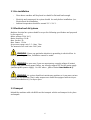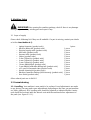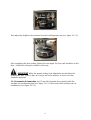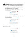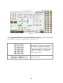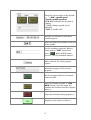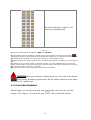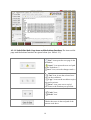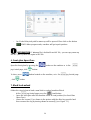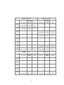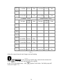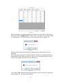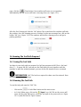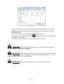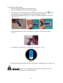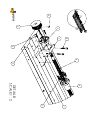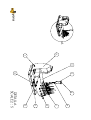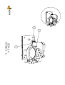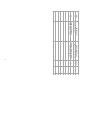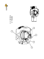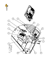
1
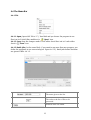
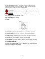
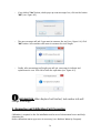
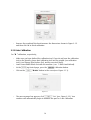
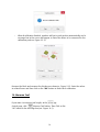
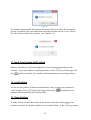
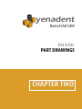
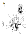
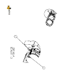
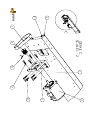
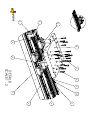
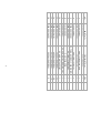
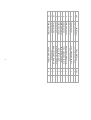
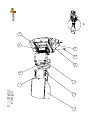
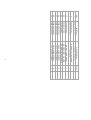
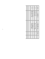
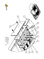
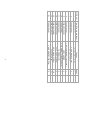
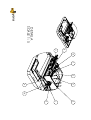
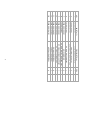
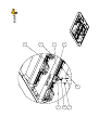
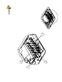
yenadent
Dental CAD CAM
INSTRUCTION MANUAL
D14 & D15
TABLE OF CONTENTS
FOREWORD
3
1. General Security Alerts 4
1.1 Responsibilities and Obligations 4
1.2 For Your Safety
4
2. Transport and Installation instructions
5
2.1 Pre-installation
6
2.2 Electrical and Air Systems 6
2.3 Transport
6
3. Machine Setup
7
3.2 Commissioning
7
4. Main Program Worksheets
4.1 Jog Control Worksheet
4.2 G Code Editor Worksheet
4.3 Tool Paths Worksheet
4.4 Tools Table Worksheet
4.5 Work Offsets Worksheet
4.6 The Menu Bar 25
13
13
18
20
21
24
5. Machine Heating Program To Be Run
28
6. Front glass Open-Close 29
7. Block load-unload 29
8. Tool change (Replace Tool) and New tool loading 31
9. Measuring and Calibration Part Processing
9.1 Y Axis Calibration
9.2 B Axis Calibration
37
38
10. Measure Tool
39
11. Mach Zero Position-Park Position 40
12. Load Position
40
13. Clean Position
40
14. Running The Tool Path Prepared 41
36
TABLE OF CONTENTS
14.1 Saving The Tool Path
14.2 Running The Tool Path
41
41
15. Cutting oil preparation for wet system .
15.1 WET System components 43
15.2 Preparation of the cutting liquid
43
43
FOREWORD
Thank you for choosing Yenadent D15. Before you start using Yenadent D15, please
carefully read the instructions for use and safety warnings. Make sure all machine
operators read this manual before using the machine.
Keep this guide at hand for quick reference. In the event of questions and
problems , please read this user guide or contact Yena Makina A.Ş.
IMPORTANT When you receive the machine, please check if there is any
damage during shipping and any missing part and report to the dealer or Yena Makina
A.Ş.
!
!3
yenadent
Dental CAD CAM
D14 & D15
INSTRUCTIONS
CHAPTER ONE
1. General Security Alerts
This section is to use the machine safely and contains important information.
1.1 Responsibilities and Obligations
All the information in this user guide must be taken into account. Knowledge of basic
security warnings and safety instructions is essential for safe and reliable usage of the
machine.
Administrative responsibilities :
The operators with the knowledge as indicated below can be allowed to use the
machine:
• Basic occupational safety and accident prevention instructions
• Trained well in the operating of the machine
• Well studied this user manual.
• Aware of the warning signs on the machine
The operator’s responsibilities;
All related operators must comply with.
• Occupational safety and accident prevention measures.
• "General safety warnings" of this guide must.
• Technical specifications of the machine
• Informing his managers in case an unsafe situation and not to continue using the
machine.
1.2 For Your Safety
To ensure correct and safe usage and avoid damage to your machine or injury or to help
prevent injury to other people, before you begin using your machine, please read
carefully all the following safety measures.
Security alerts, triangle-shaped security symbol and it is marked with the keyword from
in front. Keyword (WARNING, WARNING, etc.), defines the degree of danger that may
occur and is as noted below.
!4
WARNING I case of ignoring instructions marked with this symbol ,personal
injury or death and damage to the machine may result in.
!
WARNING Ignoring instructions marked with this symbol can result in damage
!
to the machine.
IMPORTANT Instructions marked with this symbol indicate measures to be
!
taken to avoid machine faults and breakdowns.
INFORMATION This symbol indicates useful information and tips for efficient
!
usage of your machine.
2. Transport and Installation instructions
IMPORTANT Care should be taken during transport and installation as
all mechanical and electronic parts of the machine are very fragile to
vibration and shocks.
!
IMPORTANT Transport and loading/unloading should be made by expert
!
companies.
IMPORTANT Before you unload your machine from the vehicle, make sure tilt
!
indicator and impact indicator is OK. These are to check if machine had an impact during
the transport or tilted more than a certain angle.
!5
2.1 Pre-installation
•
Floor where machine will be placed on should be flat and hard enough.
•
Electricity and compressed air system should be ready before installation. (see
Electrical and Air Installation.
Ambient temperature should be around 22 ° C-24 ° C .
•
2.2 Electrical and Air Systems
Machine electrical air system should be as per the following specification and prepared
by the experts.Y
Mains voltage: 220V. (AC.)
Mains frequency: 50 Hz.
Max. Current: 7A.
Max. Power: 1.5 Kw.
Air pressure range: min. 5.5 – Max. 7 bar
The amount of air used: min. 240 l/min.
WARNING Please pay particular attention to grounding in electrical line. In
!
case of grounding problem, installation cannot be made.
WARNING In your area, if you are experiencing a supply voltage of instant
!
changes and often having power failure, we strongly suggest UPS for the mains supply
(uninterruptible power supply) . For UPS values , please contact Yena Makina A.Ş.
WARNING Air system should not contain any moisture as it can cause serious
!
damages in the machine. That is why compressors should be equipped with air dryers.
Consult Yena Makina A.Ş. for dryer specs.
2.3 Transport
Unload the machine with a forklift from the transport vehicle and transport to its place
and unpack.
!6
3. Machine Setup
IMPORTANTAfter opening the machine package, check if there is any damage
during transport and any missing part and report if any.
!
3.1 Scope of supply
Please check following list if they are all available. If a part is missing, contact your dealer
or let the Yena Makina A.Ş..
◦
◦
◦
◦
◦
◦
◦
◦
◦
◦
◦
◦
◦
◦
◦
Laptop Computer (product code)
Wireless Mouse Kit (product code)
Electrical supply cable (product code)
USB Cable (product code)
Vacuum Cable (product code)
Caliper (product code)
3 mm T Allen Key (product code)
4 mm T Allen Key (product code)
5 mm T Allen Key (product code)
10 mm PMMA block (product code)
2 mm PMMA Calibration Milling tool (product code)
∅12 mm PU Pneumatic Hose (product code)
Spindle cleaning kit (product code)
Machine Parameter Backup (USB memory) (product code)
User Guide (product code)
1 piece.
1 piece
1 piece.
1 piece
1 piece.
1 piece
1 piece
1 piece
1 piece
1 piece
1 piece
1 piece
1 piece
1 piece
1 piece
Other ordered parts are in list EK-1
3.2 Commissioning
3.2.1 Levelling; Your machine is now ready to be replaced. Level adjustments are made
in our factory. You may make some adjustments depending on the base you put machine
on( Table, platform). All 4 levelling pads should be adjusted as indicated below. Counter
nuts should be loosened with the wrench sent with the machine before adjustment of
the pads.(see. Figure 3.2.1.1).
!7
!
Figure 3.2.1.1
Then adjust the height of the machine from the levelling adjust nut (see. Figure 3.2.1.2).
!
Figure 3.2.1.2
After completing the level setting, tighten the nuts again. The four pads should be on the
floor . Finish floor setting the machine in this way.
IMPORTANT While the ground setting, level adjustment nut should not be
turned more than 3 (three) laps as it can go out of the machine. In such a case bas
should be improved.
!
3.2.2 Pneumatic Air Connection; Put 12 mm PU Pneumatic hose supplied with the
machine into conditioning unit (see. Figure 3.2.2.1). Then enter other end into your air
installations (see. Figure 3.2.2.2).
!8
!
!
Figure 3.2.2.1
Figure 3.2.2.2
INFORMATION ∅12 mm PU Pneumatic Hose should be connected well to both
!
ends to avoid air leakage
INFORMATION An air valve should be available at the exit of the air supply
!
line to close the air system in case of servicing.
3.2.3 Wiring Connections; Now let's energise your machine to start up. To do this, follow
the following procedures step by step.
• Remove carefully laptop computer sent with the machine
• Insert charge adaptor into laptop power socket. (see. Figure 3.2.3.1).
!
Figure 3.2.3.1
!9
•
Plug the adapter into mains outlet (see. Figure 3.2.3.2).
!
Figure 3.2.3.2
•
Remove wireless mouse sent.
•
Mouse "USB Dongle" to connect to the USB port of your computer (see. Figure
3.2.3. and Figure 3.2.3.4).
!
•
Figure 3.2.3.3
!
Figure 3.2.3.4
Connect USB cable sent with the machine with one end in the laptop and the
other in the machine USB port at the back of the machine. (see. Figure 3.2.3.5 and
Figure 3.2.3.6).
!
!
Figure 3.2.3.5
!10
Figure 3.2.3.6
•
Connect machine power cable between machine power socket and mains plug.
(see Figure. 3.2.3.7 and see. Figure 3.2.3.8).
!
•
!
Figure 3.2.3.7
Figure 3.2.3.8
Your machine has been manufactured according to the vacuum system. Within the
program it allows you to control the vacuum system connected to the machine.
On the back side of your machine there is a port to control on/off positions of
vacuum system.
This output socket can control your vacuum system available.More details can be
obtained from Yena Makina A.Ş.
INFORMATION To work more efficiently, we recommend you the Yena
!
Vacuum System. For more info please contact Yena Makina A.Ş.
•
Machines with WET system, water pump on/off port (output socket) is available.
This socket is located on the back of the machine (see. Figure 3.2.3.9).
!
Figure 3.2.3.9
The machine is now ready to energise.
3.2.4 Machine First Start; After you make all cable connections, start your computer, and
then follow the steps mentioned below.
!11
IMPORTANT All installation and user settings of your laptop computer has
!
been made in our factory. These installation and user settings cannot be modified
without the consent of Yena Makina A.Ş.
•
•
•
Turn On(1)/Off(0) switch to On(1) at mains inlet. (see. figure 3.2.12). Touch
buttons in front of the machine will be illuminated.
On the computer screen, double click the "YenaCNC" icon.
YenaCNC program will start working. The next message box informing you that the
system will become active on the screen. Click on the button "OK" (see. Figure
3.2.13). System is active.
!
•
Figure 3.2.13
To go to the reference points of the machine a new message box will come the
screen. Click on “OK” button (see. Figure 3.2.14). The machine will begin to move
to go to the reference points.
!
Figure 3.2.14
After moving to reference points, machine has a message to run warm up program.
Click on the button "Yes" (see. Figure 3.2.15). Your machine will run automatically
Machine Warming Up Program.
!
Figure 3.2.15
!12
INFORMATION There is 2 mm PMMA calibration tool in its slot of the tool
!
changer and machine will pick up this tool before starting warm up cycle.
INFORMATIONIf there is no tool fitted in the tool changer or in the spindle ,
!
then find the tool and insert it by applying “8. Tool Change (Replace Tool) and New Tool
Loading” procedure.
IMPORTANT Do not run spindle without tool fitted as this will damage the
!
spindle.
IMPORTANT Warm Up cycle heats the parts of the machine to working
temperature. All settings should be made after you run this program on your machine.
!
IMPORTANT If the machine does nut operate more than 2 hours, you have to
run warm up cycle before operating the machine again. ( See “Warmup. ngc” Machine
Warm Up Program).
!
When warm up program is finished, your machine will stop by going to the park position.
Then the calibration can be done. Save the measurement results of the calibration. Now
your machine is ready for use (see. Measuring and calibration part machining).
4. Main Program Worksheets
4.1 Jog Control Worksheet
In this worksheet, the control of machine movements and peripherals is provided (see.
Figure 4.1). To open the page, click the !
Jog Control.
WARNINGButtons that can provide manual movements of the machine in this
!
section are not active. Activation authorisation is given only to responsible persons.
WARNING Before fixing any part in the machine, make sure manual
!
movement buttons are not active. Otherwise inform the responsible person.
!13
!
Figure 4.1
4.1.1 Jog Control Worksheet Icons and the button Functions; The icons on this page
and the button functions are given below (see. Table 4.1.1)
!
!
According to the work of the machine or
the machine's coordinates, indicates
linear axes in millimeters (mm) and the
rotary axis in degrees (°).They can be
“work” or “machine” coordinates as
shown on the table.
Axis speed values
!14
Shows the current status of the Spindle
(2). “…RPM”; spindle speed
“Speed"; spindle speed set
"CV & CCV"; indicates the direction of
rotation.
"! POT"; changes spindle speed
manually
“100% "; spindle load
!
Indicates the amount of time when
machining parts.
!
!
work coordinates and number of the tool
in the spindle
Run the machine registered. When a
value entered, ”MDI" button turns
!
green. !
When (START) button
pressed , run the command entered.
When selected, the same program
repeats
!
Shows the progress of the current
program
!
!
!
!
!
Run the program called or commands
entered in MDI
Stops the running program. If "FEED
HOLD" button is pressed again, the
machine will continue from the stopped
point (3).
Stops the currently running program (4).
Activates servo motors and drives
!15
Virtual Emergency-Stop button stops the
movement of the axis and spindle.
!
Percentage of feed rate to set feed rate
!
Manual axis movements , continuous or
as per set values. Linear axes in mm,
rotary axis moves in degrees (5).
!
Manual axis movement direction
buttons.
!
Rotary axes (A&B) manual movement
direction buttons.
!
Manual axis movements, fast or slow
!
"Air cooling" power button.
!
!
"Water cooler" power button (Just for
model with WET).
"Work Lamp" power button.
!
“Vacuum unit" power button.
!
Manual tool change button.
!
!
Indicates if air pressure is OK or not
!
Shows tool measuring switch is activee
or not
!
Indicates whether the Spindle is running
or not
!
Starts tool measuring process
!16
Starts the process of automatic tool
change.
!
The machine starts the calibration
process.
!
Shows the active work coordinates
!
Distances to the reference points as per
active work coordinates
!
Reset linear axes as per work
coordinates “Part Zero (7)".
“X = 0” ; Only resets the X axis.
“Y = 0” ; Only resets the Y axis.
“Z = 0” ; Only resets the Z axis.
“X and Y = 0” ; Resets both X and Y
axes.
“ALL” ; Reset all X, Y, and Z axes
!
!
!
!
Send machine to reference( parking)
point
Send axis to the suitable position for
easy loading/unloading
Send axis to the suitable position for
easy cleaning
!17
The most used letters, numbers, and
short cuts virtual keyboard.
!
Table 4.1.1
(1). Click to switch between coordinates, "Work" and "Machine"
(2). The machine starts to machine the part as per the values entered. If you click on the button !
(STOP) during operation, the program stops but the spindle continues to run. Clicking CV stops the spindle.
(3). Peripheral units (spindle, air cooling, water cooling, etc.) will continue to work.
(4). When programs are stopped between lines, peripheral units (spindle, air cooling, etc.) will continue to
work.
(5). Buttons turn green when clicked.. In continuous mode , axis move continuously as you press axis
buttons. If other steps are selected, each time you press the button, axis moves a distance of your choice.
(6). Linear axes "mm", rotary axes "° (degrees)"
(7). Part Zero: Reference point of the part as per machine coordinates
WARNINGWhen your machine is machining a piece, if you click on the button
!
!
(STOP) during operation, program stops. But the spindle continues to run. When
you click on CV , spindle stops.
4.2 G Code Editor Worksheet
With this page, you can call a tool path, edit a tool path in the screen and save the
changes. (see. Figure 4.2). To open the page !
!18
click G Code Editor button.
!
Figure 4.2
4.2.1 G Code Editor Work Page Icons and the buttons Functions; The icons on this
page and the buttons functions are given below (see. Table 4.2.1).
“! New" icon opens the new page in the
worksheet.
“! Open” icon opens the new tool path
on the worksheet (1).
! Save” icon, saves the changes made (2).
!
“!
Cut” icon, it cuts the selected row/
rows in the worksheet.
“! Copy” icons on the worksheet copies
selected row/rows.
“! Paste” icon, paste cut or copied
row7rows to the location you specified
!
!
!
“!
“!
Undo” icon,
Redo” icon
Checks the errors in the tool path of the
current work sheet
!19
Shows the coordinates of the axis.Linear
axes in millimeters (mm), rotary axis in
degrees (°)
!
!
!
Indicates the lowest and highest axis
speeds.
Indicates number of the tools to be called
in the tool path used
Table 4.2.1
(1). when you click on the icon, NGC file opens in "C:\" hard disk.
(2). When saving, changes are saved in the original file as well.
4.3 Tool Paths Worksheet
This worksheet examine the virtual movements of the machine (see. Figure 4.3). Click on
!
the button Tool Paths to open the page !
.
Figure 4.3
!20
4.3.1 Tool Paths Worksheet Icons and the buttons Functions; The icons on this page
and the buttons functions are given below (see. Table 4.3.1).
By left clicking the mouse and holding
enables you to look at the tool path from
different angles.
!
By left clicking the mouse and holding
enables you to move tool path in a linear
way.
!
Zoom in/out of virtual tool path
!
Shows virtual tool path in XY plane
!
Shows virtual tool path in XZ plane
!
Shows virtual tool path in 3D
!
Virtual tool path back to XY plane
!
Shows virtual tool path in screen by recalculating
!
Table 4.3.1
4.4 Tools Table Worksheet
This worksheet contains information on positions of the tools and tool measuring probe
as per machine coordinates, tool life . (see. Figure 4.4).
Click on the button !
Tools Table to open the page
!21
!
Figure 4.4
WARNINGThis section was closed in software for use by the operator. The
!
buttons are active only with the permission of the authorised person . Do not make any
change in settings on this page as it may result in permanent damage to your machine.
4.4.1 Tools Table Worksheet Icons and the buttons Functions; On this page are given
in the following table of icons and buttons functions (see. Table 4.4.1).
Indicates the number of tools used (1).
!
!
Tool number given in the table
!
Sister tool group
!
Resets the currently selected tool life in
tool table.
Tool properties of the selected tool
!
!
Tool length measurement before and during
machining
!22
Rechecks tool length in the given intervals
in minutes
!
Allowed length difference value
!
Shows the table of tools used.
!
Shows tool length measurement,tool pick
up, tool drop coordinate list
!
Activate tool length measurement after
tool pick up
!
Allows checking coordinate list by
jogging without axis movements
!
Allows tool no 1coordinates to be
referenced for other tools in the list
!
Allows selected tool in tool table as
reference tool.
!
!
Allows selected tool in tool table as
measuring probe.
!
Opens the table of “P” coordinates.
!
Opens the table of “S” coordinates
!
Opens the table of “SN” coordinates.
!
When you click the button , just makes the
process of measuring the tool.
!
When you click the button , just makes the
process of picking up the tool.
!
When you click the button just makes the
process of dropping the tool.
!
!23
In “Tools Table "page saves all changes
you made.
!
!
Table 4.4.1
(1). This includes the reference tool.
(2). Error message given if the difference is bigger than given value after measuring.
(3). The reference tool not included.
4.5 Work Offsets Worksheet
Different work coordinates can be defined in the control. You will find list of work
coordinates in this work sheet as per machine coordinates.(see. Figure 4.5). Click on the
!
button !
Work Offsets to open the page.
Figure 4.5
WARNING This section was closed in software for use by the operator. The
!
buttons are active only with the permission of the authorised person . Do not make any
change in settings on this page as it may result in permanent damage to your machine.
!24
4.6 The Menu Bar
4.6.1 File
!
Figure 4.6.1
4.6.1.1 Open; Opens NGC file in "C:\" hard disk and you choose the program to run.
Short cut in G Code Editor worksheet is ! "Open" icon.
4.6.1.2 Save; Save the changes made G code editor sheet.Short cut in G code editor
sheet is ! "Save" icon.
4.6.1.3 Batch Jobs; On the same block if you want to run more than one program, you
define the programs to run successively(see. Figure 4.6.1.3). Batch Jobs button functions
are given in Table 4.6.1.3.
!
Figure 4.6.1.3
The name given to the list .
!
The order to the list of files to be
processed.
!
Position of the file called
!
!25
The file status.
!
The number of lines in the file to be
processed.
!
Work coordinate of the file to be run
!
Allows you to switch between the files.
!
Adds rows to the list.
!
Deletes rows from the list.
!
Deletes all rows in the list.
!
Checks the tool path of the file in selected
line
!
Checks the tool path of the all files in the
list
!
Initializes the execution of programs in the
list.
!
Specifies number of next file to run
!
Exits from page.
!
Saving changes and exits from the page.
!
Tablo 4.6.1.3
INFORMATION In 4 axis machines, you can make batch jobs at the same time
!
for the left and right block.
4.6.1.4 Auto tool length check; As per the given time interval and difference, it checks
the tool length during machining. If the length is above the limits, machine takes the
sister tool automatically.
With the sister tool , program restarts several lines from behind of the stopped line which
can be definable.
4.6.1.5 Enable eMail/SMS; The required mail settings should be done and your machine
must have a seamless internet connection. Machine can send email to a given e-mail
address for machine situation, work end, restart, tool change, etc.
Please contact Yena Makina A.S for e-mail settings.
!26
4.6.1.6 Login/Logout; Buttons for the manual movements of the machine and
adjustments parameters restricted to operator. This feature opens and closes this
restricted features. Contact Yena Makina A.S for passwords.
!
WARNING Manual movement activation is only permitted to authorised person.
!
WARNING
Before fixing any part in the machine, make sure manual movement buttons are not
active. Otherwise inform the responsible person.
4.6.1.7 Exit; Exit YenaCNC program.
4.6.2 Edit
!
Figure 4.6.2
4.6.2.1 G Code; G Code Editor page opened (see 4.2 G Code Editor worksheet).
4.6.2.2 Tools Table; Tools Table page opened (see 4.4 Tools Table worksheet).
4.6.2.3 Work Offsets; Work offset page opened(see 4.5 Work Offsets worksheet).
4.6.2.4 Find; Same letters and words found in G Code Editor page.
4.6.2.5 Find next; Same letters and words found in G Code Editor page successively.
4.6.3 Diagnostics and Setup
This section was closed in software for use by the operator. Only authorised technical
service of Yena Makina A.S can intervene.
!27
!
Figure 4.6.3
4.6.4 Mapping
This section was closed in software for use by the operator. Only authorised technical
service of Yena Makina A.S can intervene.
4.6.5 Help
!
Figure 4.6.4
4.6.5.1 Index; Unavailable.
4.6.5.2 About; Information on software version.
5. Machine Heating Program To Be Run
Follow the following steps to run warm up program:
•
Click !
•
In G Code Editor page click on the "! Open" icon. NGC file on the screen will
open. On the page , select the file (see the "Warmup". Figure 5.1) and click
"Open" button.
G Code Editor button on the main screen
!28
!
On G Code Editor,tool path for warm up will be opened .Then click on the button
•
!
!
Figure 5.1
START. When program ends, machine will go to park position.
INFORMATION If Warmup file is deleted from NGC file, you can copy warm up
file in C:\MCTL\Parms file again in NGC file.
6. Front glass Open-Close
Open the front glass by pressing the !
Jog Control page, click !
To close, press !
, click!
button on the machine or in the
!
button.
button located on the machine, or in the !
Jog Control page
button.
7. Block load-unload
Follow the steps below to load a new block or unload machined block.
•
•
At the !
Jog Control page press the !
Load button.
Open the front glass after the machine come to Load position.(See front Glass
Open-Close)
Loosen the screws (1) as shown in the picture with the allen key provided and
then remove the ring by turning shown in arrows(2).(see. Figure 7.1).
!29
!
•
Figure 7.1
Load the block to be machined.(see. Figure 7.2).
!
•
Figure 7.2
Replace the ring in arrow direction (1) and tighten the screws as shown(2) .In this
way, load the PMMA block (see. Figure 7.3).
!
Figure 7.3
!30
IMPORTANT Before you unload the block , make sure that program is finished
and the spindle is completely stopped.
!
IMPORTANTMake sure that you tightened the rings correct. Over tightness can
damage the screws or loose screws can result in tool breakage or bad machining results.
!
8. Tool change (Replace Tool) and New tool loading
You can use tool change and tool load operations when you are first installing the
machine ,changing a worn or broken tool or define a tool to a slot.
Slot numbers of the tools on tool changer are given in table 8.1 for D14 and in 8.2 for
D15
ZIRCON TOOLS
METAL TOOLS
Tool Type
Cutting
length
Code
Tool Type
Cutting
length
Code
SLOT
1
2 mm Ball
16 mm
T101
-
-
-
SLOT
2
1 mm Ball
16 mm
T102
-
-
-
SLOT
3
-
-
-
2 mm Ball
12 mm
T202
SLOT
4
-
-
-
1 mm Ball
12 mm
T203
SLOT
5
-
-
-
-
-
-
SLOT
6
-
-
-
-
-
-
SLOT
7
-
-
-
2 mm Ball
12 mm
T202
SLOT
8
0.6 mm Ball
10 mm
T103
0.6 mm
Ball
10 mm
T204
PMMA TOOLS
WAX TOOLS
!31
TOOL
TYPE
Cutting
length
CODE
TOOL
TYPE
Cutting
length
Code
SLOT
1
-
-
-
-
-
-
SLOT
2
-
-
-
-
-
-
SLOT
3
-
-
-
-
-
-
SLOT
4
-
-
-
-
-
-
SLOT
5
2 mm Ball
16 mm
T302
2 mm Ball
16 mm
T302
SLOT
6
1 mm Ball
16 mm
T303
1 mm Ball
16 mm
T303
SLOT
7
-
-
-
-
-
-
SLOT
8
0.6 mm Ball
10 mm
T103
0.6 mm
Ball
10 mm
T103
CERAMIC TOOLS
CALIBRATION TOOLS
Tool Type
Cutting
length
code
Tool Type
Cutting
length
Code
SLOT
1
-
-
-
-
-
-
SLOT
2
-
-
-
-
-
-
SLOT
3
-
-
-
-
-
-
SLOT
4
-
-
-
-
-
-
SLOT
5
2 mm Ball
16 mm
T401
-
-
-
SLOT
6
1.2 mm Ball
16 mm
T402
-
-
-
SLOT
7
-
-
-
-
-
-
SLOT
8
0.8 mm Ball
16 mm
T403
2 mm Flat
16 mm
T301
Table 7.1
!32
ZIRCON TOOLS
METAL TOOLS
Tool type
Cutting
length
Code
Tool type
Cutting
length
Code
SLOT
1
2 mm Ball
16 mm
T101
-
-
-
SLOT
2
1 mm Ball
16 mm
T102
-
-
-
SLOT
3
-
-
-
2 mm Ball
12 mm
T202
SLOT
4
-
-
-
1 mm Ball
12 mm
T203
SLOT
5
-
-
-
-
-
-
SLOT
6
-
-
-
-
-
-
SLOT
7
-
-
-
2 mm Ball
12 mm
T202
SLOT
8
0.6 mm Ball
10 mm
T103
0.6 mm Ball
10 mm
T204
PMMA TOOLS
WAX TOOLS
Tool type
Cutting
length
CODE
Tool type
Cutting
length
CODE
SLOT
1
-
-
-
-
-
-
SLOT
2
-
-
-
-
-
-
SLOT
3
-
-
-
-
-
-
SLOT
4
-
-
-
-
-
-
SLOT
5
2 mm Ball
16 mm
T302
2 m Ball
16 mm
T302
!33
SLOT
6
1 mm Ball
16 mm
T303
1 mm Ball
16 mm
T303
SLOT
7
-
-
-
-
-
-
SLOT
8
0.6 mm Ball
10 mm
T103
0.6 mm Ball
10 mm
T103
CERAMIC TOOLS
CALIBRATION TOOLS
Tool type
Cutting
length
Code
Tool type
Cutting
length
Code
SLOT
1
-
-
-
-
-
-
SLOT
2
-
-
-
-
-
-
SLOT
3
-
-
-
-
-
-
SLOT
4
-
-
-
-
-
-
SLOT
5
2 mm Ball
16 mm
T401
-
-
-
SLOT
6
1.2 mm Ball
16 mm
T402
-
-
-
SLOT
7
-
-
-
-
-
-
SLOT
8
0.8 mm Ball
16 mm
T403
2 mm Flat
16 mm
T301
Table 7.2
Follow the steps below for tool change and tool loading.
INFORMATION In the !
!
corner !
Jog Control page, located at the bottom-left
"T3" show the current tool in the spindle.
In the !
Jog Control page , click !
come (see. Figure 7.1).
Replace Tool button. Tool table page will
!34
!
•
•
Figure 7.1
Write tool number you want to define or change into Tool No box or click No box.
Click on the button "Replace Tool”. On the screen, you will see a message asking
for confirmation . Click OK o continue or Cancel to give up(see. Figure 8.1).
!
•
•
Machine will first drop the tool in the spindle and then will get the one you
specified.
After picking up new tool, you will be asked if you want to send the machine to
park position. If you define a new tool, click Yes. If you change with one of the
tools in tool changer, then click No.(see. Figure 8.2).
!
•
Figure 8.1
Figure 8.2
If you clicked "No" button the machine will wait for you to load your new tool at
park position (see. The New Tool Loading).
!35
•
If you clicked "Yes" button, which pops up new messages box, click on the button
"OK" (see. Figure 8.3).
!
•
Figure 8.3
The new message will ask if you want to measure the tool (see. Figure 8.4). Click
"OK" button. Your machine will move to measure the tool length.
!
•
Figure 8.4
Finally, after measuring tool length you will get a message to indicate tool
replacement is over. Click OK to finish the operation.(see. Figure 8.5).
!
Figure 8.5
INFORMATION When Replace Tool finished, tool number info will
change accordingly.
!
9. Measuring and Calibration Part Processing
Calibration is required in the fist installation and in case of dimensional errors and help
eliminate this.
Before calibration warm up process is necessary (see. Machine Warm Up Program).
!36
INFORMATION If the machine has run at least 15 minutes you do not need
!
warm up procedure.
9.1 Y Axis Calibration
“Y “axis calibration, follow below respectively;
•
•
On your machine, make sure you have defined the calibration tool. Make sure
there is calibration tool in the spindle or in tool changer. Otherwise load the
calibration tool.(see 8. tool change (the Replace Tool, and the new tool load).
Fix 10 m PMMA block sent with the machineYour machine's block holder, (see. 7.
Block Load-Unload).
•
In the !
•
Click on the !
Jog Control page, click !
"Standard" button (see. Figure 9.1.1).
!
•
Figure 9.1.1
The new message box appears, click !
"Yes" (see. Figure 9.1.2). Your
machine will automatically begin to process for Y axis Calibration.
!
•
Calibration button
Figure 9.1.2
When Y calibration process finished , machine will go to park position and a
message box will appear to enter the values measured on the calibration part.
(see. Figure 9.1.3).
!37
!
•
Figure 9.1.3
Remove the machined block and measure the dimensions shown in Figure 9.1.3
and then click OK to finish calibration.
9.2 B Axis Calibration
For “B “ calibration, respectively;
•
•
Make sure you have defined the calibration tool. If you do not have the calibration
tool on the Spindle, please load calibration tool into the spindle (see calibration
tool 8. tool change (the Replace Tool, and the new tool load)).
Load 10mm PMMA block sent with the machine. (see. 7. Block Load-Unload).
•
At the !
•
Click on the !
Jog Control page, press the !
"B Axis" button in the screen(see. Figure 9.1.1).
!
•
Calibration button.
Figure 9.2.1
The new message box appears, click !
"Yes" (see. Figure 9.2.2). Your
machine will automatically begin to machine the part for Y axis Calibration.
!38
!
•
Figure 9.2.2
When B calibration finished, machine will go to park position automatically and a
message box in the screen will appear to enter the values to be measured in the
calibration part(see. Figure 9.2.3).
!
Figure 9.2.3
Remove the block and measure the thicknesses shown in Figure 9.2.3. Enter the values
to related boxes and then click on the "OK" button to finish the B calibration.
10. Measure Tool
If you want to measure tool length, at the !
Jog
Control page, click !
Measure Tool button. Then Click on the
"OK" button in the message box(see. Figure 10.1).
!39
!
Figure 10.1
The machine automatically will measure the length of the tool. When the measuring
process is complete, the screen will show a message that the process is over. Click on
the "OK" button to finish the operation (see. Figure 10.2).
!
Figure 10.2
11. Mach Zero Position-Park Position
Machine should be in Park Position(Mach Zero) if you plan any intervention to the
machine. To get your machine to parking positions, at the !
the !
Jog Control page click
Mach Zero button. Your machine will automatically go to parking positions.
12. Load Position
You can use this position to load and unload blocks easily. To bring your machine to
"Load" position, at the !
Jog Control page click on the !
machine will automatically go to load position.
Load button.Your
13. Clean Position
To make it easier to clean the interior of the machine takes the machine axis to the
positions specified. To bring the machine to the position"Clean", at the !
!40
Jog Control
page, click the !
Clean button. Your machine will come to a set position
automatically and the screen will have a message box (see. Figure 13.1).
!
Figure 13.1
After the first Cleanup job click the "OK" button. The second time the machine will take
the position. Once the cleaning process is finished, in the new message box, click on the
button "OK" (see. Figure 13.2). The machine will end the cleanup process and go to
parking positions.
!
Figure 13.2
14. Running The Tool Path Prepared
14.1 Saving The Tool Path
You have to save tool path you prepared in Cad-Cam program in NGC file in the hard
drive C:\ . To move the file, you can use the Flash drive we sent together with the
machine or with the existing network, you can do the file transfer across a network
INFORMATION "NGC" file has been opened to share over the network. Does
not require any sharing settings.
!
14.2 Running The Tool Path
To run the tool path saved in “NGC’ file:
•
Click on the !
G Code Editor button on the main screen
•
In G Code Editor page, click on the ! "Open" icon. NGC file on the screen will
open. On the page that opens, select the tool path to be processed (see. Figure
14.2.1) and click on the "Open" button.
!41
!
•
Figure 14.2.1
In the G Code Editor page, the tool path you want to open will open. Then click
!
Check For Errors button. Program will do the tool path error check in
opened tool path.
In the event of a fault, the fault line will be indicated to you.
•
•
After control of the tool path, click the !
START button. The machine will start
to machine the tool path.
At the end of the program, your machine will go to the position.
IMPORTANT Make sure the block firmly fixed to the block holder to prevent
!
tool breakage. see. 7. Block Load-Unload.
IMPORTANT Make sure tool changer contains the correct tools as per the block
!
!
you will machine to prevent tool breakage. For tool change and tool loading see. 8. Tool
change (Replace Tool) and New Tool Loading.
IMPORTANT Make sure the front glass door is closed while machining.
!42
15. Cutting oil preparation for wet system .
15.1 WET System components
A WET system set is provided with the machine including:
Water tank
1 ea.
• WET connection cable
1 ea.
• Cutting liquid
1 Liter.
• Refractometer
1 ea.
IMPORTANT Please check above components included in the WET System Set.
!
Otherwise, please inform the supplier.
15.2 Preparation of the cutting liquid
IMPORTANT Water tank capacity is 11 liter. Cutting liquid rate should be about
!
3%.
Check the rate of the cutting liquid with the refractometer provided to get better cutting
performance (see Figure 15.2.1).
!
Figure 15.2.1
!43
To prepare the cutting liquid:
• Fill in the tank with water to the indicator level.
• Add 3% cutting liquid provided with the machine.
•
•
Close the cover of the tank and at the !
Jog Control page, push !
water
cooling button to get homogenised mixture. Run about 5 minutes.
Then, with a sampling stick, put 1 or 2 drops of liquidon the shown surface (see
Figure 15.2.2).
!
!
!
Figure 15.2.2
•
Look through the hole of the refractometer towards to the light (see Figure
15.2.3).
!
Figure 15.2.3
•
You should see around 2-3% on the guage. (see Figure 15.2.4).
!
Figure 15.2.4
•
Adjust accordingly by adding water or cutting liquid depending on the value seen.
IMPORTANT Make sure “0” adjustment made in the refractometer before
!
measurement. ( see Refractometer zero adjustement )
!44
!
Figure 15.3.3
•
If the white line is not in “0” position, with a screw driver provided, adjust the line
at “0” by adjustment screw located in front of the prism cover. ( see Figure
15.3.4).
!
Figure 15.3.4
Then refractometer is ready for the measurement of your mixture prepared.
!45
yenadent
Dental CAD CAM
D14 & D15
PART DRAWINGS
CHAPTER TWO
A
5
12
2
7
1
DETAIL A
SCALE 2 : 5
21
11
22
16
10
6
30
1
2
5
6
7
10
11
12
16
21
22
30
NO
15.100.1028.01
15.100.1030.01
15.100.1035.01
15.100.1036.01
15.100.1037.01
15.500.1017.01
15.500.1018.01
1996.500.1032.02
15.100.1025.03
1996.500.1060.01
1996.500.1071.01
1996.500.1038.01
PART NO
4 AXIS ROTARY BOTTOM FLANGE
4 AXIS ATC FLANGE
4 AXIS ROTARY ALIGN FLANGE
4 AXIS GEAR FLANGE
4 AXIS BLOCK HOLDER
4 AXIS SPINEA FLANGE
4 AXIS ALIGN FLANGE
TOOL HOLDER
BLOCK HOLDER RING
5X16 ALLEN SCREW
4X8 ALLEN SCREW
BLOCK
DESCRIPTION
1
1
1
1
1
1
1
8
2
8
6
2
QTY
1
A
15
12
20
2
4
5
11
DETAIL A
SCALE 2 : 5
19
7
16
22
30
21
1
Ö
N
15.100.1028.01
15.100.1030.01
15.100.1033.01
15.100.1035.01
PART NO
1
2
4
5
15.100.1037.01
15.500.1018.01
1996.500.1032.02
1996.500.1079.01
15.100.1025.03
1996.500.1096.01
1996.500.1097.01
1996.500.1060.01
1996.500.1071.01
1996.500.1038.01
NO
7
11
12
15
16
19
20
21
22
30
4 AXIS BLOCK HOLDER
4 AXIS ALIGN FLANGE
TOOL HOLDER
5X25 ALLEN SCREW
BLOK HOLDER RING
5X10 SET SCREW
4X8 SET SCREW
5X16 ALLEN SCREW
4X8 ALLEN
BLOCK
4 AXIS ROTARY ALT FLANGE
4 AXIS ATC FLANGE
4 AXIS ATC BOTTOM SPACER
4 AXIS ROTARY ALIGN FLANGE
DESCRIPTION
1
1
8
5
2
10
2
8
6
2
1
1
3
1
QTY
1
A
30
7
19
37
36
25
9
15
DETAIL A
SCALE 1 : 2
8
5
12
1
1
5
7
8
9
12
15
19
25
30
36
37
NO
15.100.1030.01
15.100.1035.01
15.100.1037.01
15.500.1007.01
15.500.1007.02
1996.500.1032.02
1996.500.1079.01
1996.500.1096.01
1996.300.1029.01
1996.500.1038.01
1996.300.1036.01
1996.300.1037.01
PART NO
4 AXIS ATC FLANGE
4 AXIS ROTARY ALIGN FLANGE
4 AXIS BLOCK HOLDER
TOOL MEASURE PART 1
TOOL MEASURE PART 2
TOOL HOLDER
5X25 ALLEN SCREW
5X10 SET SCREW
PROXY SCREW
BLOCK
BAUMER SENSOR
BAUMER CONNECTOR
DESCRIPTION
1
1
1
1
1
8
5
10
2
2
1
1
QTY
1
4
3
9
17
DETAIL A
SCALE 2 : 5
8
A
8
2
1
17
17
7
15
16
17
8
14
18
16
17
18
15
1
2
3
4
5
6
7
8
9
10
11
12
13
14
NO
15.200.1041.01
1996.500.1092.01
1996.500.1067.01
15.200.1040.01
15.100.1031.01
15.100.1036.01
15.100.1037.01
15.500.1017.01
1996.500.1015.01
1996.500.1091.01
1996.500.1061.01
1996.500.1060.01
1996.500.1071.01
1996.300.1027.01
1996.300.1028.01
1996.300.1029.01
15.200.1042.01
1996.300.1013.01
PART NO
4 AXIS MOTOR BOTTOM COVER
3X8 YSB SCREW
5X10 ALLEN SCREW
4 AXIS ROTARY MOTOR UP COVER
4 AXIS A MOTOR FLANGE
4 AXIS GEARBOX FLANGE
4 AXIS BLOCK HOLDER
4 AXIS SPINEA FLANGE
GEARBOX
3X4 YSB SCREW
4X20 ALLEN SCREW
5X16 ALLEN SCREW
4X8 ALLEN
MAGNET
PROXY
PROXY SCREW
4 AXIS PROXY METAL
MOTOR 100 WATT
DESCRIPTION
1
10
2
1
1
1
1
1
1
6
5
10
1
1
1
1
1
1
QTY
1
A
6
DETAIL A
SCALE 1 : 2
7
NO.
6
7
1996.300.1028.01
1996.300.1029.01
PART NO
PROXY
PROXY VIDA
DESCRIPTION
1
1
QTY
1
A
10
1
5
4
3
9
DETAIL A
SCALE 1 : 2
2
8
7
6
ÖĞE
1
2
3
4
5
6
7
8
9
10
1
2
3
4
5
6
7
8
9
10
NO
15.100.1036.01
15.100.1037.01
15.500.1017.01
1996.500.1060.01
1996.300.1027.01
1996.300.1028.01
1996.300.1029.01
15.200.1042.01
1996.500.1091.01
1996.500.1099.01
PART NO
4 AXIS GEARBOX FLANGE
4 AXIS BLOCK HOLDER
4 AXIS SPINEA FLANGE
5X16 ALLEN SCREW
MAGNET
PROXY
PROXY SCREW
4 AXIS PROXY METAL
3X4 YSB SCREW
4X16 COUNTERSINK SCREW
DESCRIPTION
1
1
1
6
1
1
1
1
2
1
QTY
1
6
27
4
C
DETAIL C
SCALE 1 : 2
10
32
1
19
14
3
23
1
3
4
6
10
14
19
23
27
32
NO
15.100.1003.01
15.100.1010.01
15.500.1040.01
15.500.1048.01
1996.500.1012.01
1996.300.1013.01
1996.500.1060.01
1996.500.1063.01
1996.500.1098.01
1996.500.1097.01
PART NO
X AXIS PROFILE
X AXIS MOTOR FLANGE
X AXIS MOTOR BELT
X AXIS RAY 578 MM
MOTOR KASNAK
MOTOR 100 WATT
5X16 ALLEN SCREW
5X20 ALLEN SCREW
4X8 COUNTERSINK SCREW
4X8 SETSCREW
DESCRIPTION
1
1
1
2
1
1
14
4
11
1
QTY
1
2
5
3
B
18
8
10
15
14
DETAIL B
SCALE 1 : 2
9
13
1
4
6
4
1
2
3
4
5
6
8
9
10
13
14
15
18
NO
15.100.1003.01
15.100.1008.01
1996.500.1002.01
15.500.1048.01
1996.500.1005.01
1996.500.1006.01
15.100.1005.01
15.500.1038.01
15.100.1014.01
1996.500.1065.01
1996.500.1061.01
1996.500.1060.01
1996.500.1062.01
PART NO
X AXIS PROFILE
X BALLSCREW FLANGE
AXIS CARRIER
X AXIS RAIL 578 MM
X-Y-Z BALLSCREW CUSHIONING
X-Y-Z BALLSCREW NUT
X AXIS FLANGE
X-Y AXIS BALLSCREW 470 MM
X-Y AXIS NUT SUPPORT
4X25 ALLEN SCREW
4X20 ALLEN SCREW
5X16 ALLEN SCREW
5X30 ALLEN SCREW
DESCRIPTION
1
1
4
2
1
1
1
1
1
21
20
10
2
QTY
1
16
5
B
3
13
2
14
6
15
4
DETAIL B
SCALE 1 : 2
1
12
1
2
3
4
5
6
12
13
14
15
16
NO
15.100.1003.01
15.100.1008.01
1996.500.1005.01
1996.500.1006.01
1996.500.1011.01
15.500.1038.01
1996.500.1060.01
1996.500.1062.01
1996.500.1061.01
1996.500.1098.01
1996.500.1097.01
PART NO
X AXIS PROFILE
X BALLSCREW FLANGE
X-Y-Z BALLSCREW
X-Y-Z BALLSCREW NUT
AXIS BALLSCREW PULLEY
X-Y AXIS BALLSCREW 470
5X16 ALLEN SCREW
5X30 ALLEN SCREW
4X20 ALLEN SCREW
4X8 COUNTERSINK SCREW
4X8 SET SCREW
DESCRIPTION
1
1
1
1
1
1
6
2
6
6
1
QTY
1
3
9
1
6
2
3
NO
1
2
3
6
9
PART NO
15.100.1003.01
1996.500.1002.01
15.500.1048.01
1996.500.1065.01
1996.500.1098.01
X AXIS PROFILE
AXIS CARRIER
X AXIS RAIL 578 MM
4X25 ALLEN SCREW
4X8 COUNTERSINK SCREW
DESCRIPTION
1
4
2
21
6
QTY
1
A
7
6
8
3
DETAIL A
SCALE 1 : 2
4
5
2
1
ÖĞE
1
2
3
4
5
6
7
8
NO
1
2
3
4
5
6
7
8
PART NO
15.100.1003.01
15.500.1048.01
1996.300.1030.01
15.200.1017.01
1996.500.1065.01
1996.500.1092.01
1996.500.1090.01
1996.500.1098.01
X AXIS PROFILE
X AXIS RAY 578 MM
X-Y-Z AXIS HOME SWITCH
X AXIS SWITCH SHEET METAL
4X25 ALLEN SCREW
3X8 YSB SCREW
2,5X10 YSB SCREW
4X8 COUNTERSINK SCREW
DESCRIPTION
1
2
1
1
21
2
2
6
QTY
1
24
27
31
B
28
6
29
17
12
1
27
11
25
19
DETAIL B
SCALE 1 : 2
1
6
11
12
17
19
24
25
27
28
29
31
NO
15.100.1003.01
15.500.1048.01
15.100.1005.01
15.500.1038.01
1996.500.1065.01
1996.500.1060.01
15.200.1039.01
15.200.1025.01
1996.500.1098.01
15.500.1041.01
15.200.1018.01
1996.500.1091.01
PART NO
X AXIS PROFILE
X AXIS RAIL 578 MM
X AXIS FLANGE
X-Y AXIS BALLSCREW 470 MM
4X25 ALLEN SCREW
5X16 ALLEN SCREW
X AXIS SIDE BELLOW METAL
X AXIS MIDDLE LEFT BELLOW METAL
4X8 COUNTERSINK SCREW
X BELLOW
X BELLOW PROTECTION UP METAL
3X4 YSB SCREW
DESCRIPTION
1
2
1
1
21
14
2
1
11
2
1
22
QTY
1
DETAIL A
SCALE 2 : 5
A
14
4
9
8
6
15
11
10
13
1
7
2
3
12
1
2
3
4
6
7
8
9
10
11
12
13
14
15
NO
1996.300.1013.01
1996.500.1015.01
15.100.1022.01
1996.300.1030.01
15.100.1016.02
15.100.1017.02
15.100.1018.02
15.100.1019.02
1996.500.1091.01
1996.500.1060.01
1996.500.1073.01
15.200.1017.02
1996.500.1090.01
1996.500.1063.01
PART NO
MOTOR 100 WATT
GEARBOX
B AXIS MOTOR FLANGE
X-Y-Z AXIS HOME SWICTH
ROTARY BOTTOM TABLE
B AXIS ROTARY FLANGE
A AXIS ROTARY FLANGE
BLOCK HOLDER
3X4 YSB SCREW
5X16 ALLEN SCREW
4X30 ALLEN SCREW
B AXIS SWICTH METAL
2,5X10 YSB SCREW
5X20 ALLEN SCREW
DESCRIPTION
1
1
1
1
1
1
1
1
6
4
4
1
2
4
QTY
1
A
10
7
11
2
13
6
4
1
8
5
9
DETAIL A
SCALE 2 : 5
1
2
4
5
6
7
8
9
10
11
13
NO
1996.500.1032.01
15.500.1007.01
1996.300.1036.01
1996.300.1037.01
15.500.1007.02
1996.500.1081.01
1996.500.1096.01
15.100.1016.02
15.100.1017.02
15.100.1020.02
1996.500.1078.01
PART NO
3MM TOOL HOLDER
TOOL MEASURE PART 1
BAUMER SENSOR
BAUMER CONNECTOR
TOOL MEASURE PART 2
4X10 ROUND SCREW
5X10 SET SCREW
ROTARY BOTTOM TABLE
B AXIS ROTARY FLANGE
ATC FLANGE
6X40 ALLEN SCREW
DESCRIPTION
8
1
1
1
1
2
9
1
1
1
2
QTY
1
A
3
29
22
30
23
26
2
1
27
DETAIL A
SCALE 1 : 2
12
1
2
3
12
22
23
26
27
29
30
NO
1996.300.1013.01
15.100.1021.01
1996.500.1015.01
15.200.1014.02
15.100.1017.02
15.100.1018.02
1996.500.1077.01
1996.500.1066.01
1996.500.1060.01
1996.500.1074.01
PART NO
MOTOR 100 WATT
A AXIS MOTOR FLANGE
GEARBOX
A AXIS COVER METAL
B AXIS ROTARY FLANGE
A AXIS ROTARY FLANGE
4X45 ALLEN SCREW
4X16 ALLEN SCREW
5X16 ALLEN SCREW
4X6 ROUND SCREW
DESCRIPTION
1
1
1
1
1
1
3
4
4
6
QTY
1
A
17
19
16
12
DETAIL A
SCALE 2 : 5
14
12
14
16
17
19
NO
15.100.1017.02
15.100.1019.02
15.500.1053.01
1996.500.1045.01
1996.500.1110.01
PART NO
B AXIS ROTARY FLANGE
BLOCK HOLDER
FREEMILL HOLDER
9MM FREEMILL
3X4 SET SCREW
DESCRIPTION
1
1
1
1
1
QTY
1
A
18
17
16
DETAIL A
SCALE 2 : 5
Ö
16
17
18
NO
15.500.1053.01
1996.500.1080.01
1996.500.1110.01
PART NO
FREEMILL HOLDER
4X6 ROUND SCREW
3X4 SET SCREW
DESCRIPTION
1
1
1
QTY
1
A
DETAIL A
SCALE 2 : 5
17
25
12
24
19
12
17
19
24
25
NO
15.100.1025.01
1996.500.1038.01
1996.500.1064.01
15.100.1018.02
15.100.1019.02
PART NO
BLOCK HOLDER RING
BLOCK
4X10 ALLEN SCREW
A AXIS ROTARY FLANGE
BLOCK HOLDER
DESCRIPTION
1
1
3
1
1
QTY
1
13
29
A
14
12
4
31
17
1
16
18
31
8
28
9
20
DETAIL A
SCALE 1 : 2
1
4
8
9
12
13
14
16
17
18
20
28
29
31
NO
15.100.1001.01
15.100.1011.01
15.500.1009.01
1996.300.1013.01
15.500.1038.01
15.500.1042.01
1996.500.1005.01
1996.500.1011.01
1996.500.1012.01
15.100.1009.01
1996.500.1066.01
1996.500.1063.01
1996.500.1069.01
1996.500.1097.01
PART NO
MAIN BOTTOM TABLE
Y AXIS BALLSCREW FLANGE
Y AXIS MOTOR BELT
MOTOR 100 WATT
X-Y AXIS BALLSCREW 470
Y AXIS BELLOW
X-Y-Z BALLSCREW
AXIS BALLSCREW
MOTOR PULLEY
Y AXIS MOTOR FLANGE
4X16 ALLEN SCREW
5X20 ALLEN SCREW
6X80 ALLEN SCREW
4X8 SET SCREW
DESCRIPTION
1
1
1
1
1
2
1
1
1
1
18
4
4
2
QTY
1
A
1
6
20
18
11
21
2
19
DETAIL A
SCALE 1 : 2
3
9
18
10
ÖĞE NO.
1
2
3
6
9
10
11
18
19
20
21
PARÇA NUMARASI
15.100.1001.01
15.500.1050.01
15.100.1006.01
15.200.1020.01
1996.500.1002.01
15.500.1038.01
15.500.1042.01
1996.500.1067.01
1996.500.1068.01
1996.500.1091.01
15.200.1024.01
MAIN BOTTOM TABLE
Y AXIS RAIL 420 MM
Y AXIS FLANGE
Y AXIS FRONT BELLOW METAL
AXIS CARRIER
X-Y AXIS BALLSCREW 470 MM
Y AXIS BELLOW
5X10 ALLEN SCREW
4X12 ALLEN SCREW
3X4 YSB SCREW
Y AXIS SIDE PROTECTION
TANIM
1
2
1
1
4
1
2
5
16
21
2
MİKT.
1
A
14
9
8
2
12
4
8
DETAIL A
SCALE 1 : 2
12
3
15
14
7
1
1
2
3
4
7
8
9
12
14
15
NO
15.100.1001.01
15.500.1050.01
15.100.1006.01
15.100.1014.01
1996.500.1002.01
1996.500.1060.01
1996.500.1066.01
1996.500.1068.01
15.200.1024.01
1996.500.1081.01
PART NO
MAIN BOTTOM TABLE
Y AXIS RAIL 420 MM
Y AXIS FLANGE
X-Y AXIS NUT SUPPORT
AXIS CARRIER
5X16 ALLEN SCREW
4X16 ALLEN SCREW
4X12 ALLEN SCREW
Y AXIS SIDE PROTECTION
4X10 ROUND SCREW
DESCRIPTION
1
2
1
1
4
9
14
16
2
6
QTY
1
A
DETAIL A
SCALE 1 : 5
8
11
10
7
2
17
4
18
3
1
9
1
2
3
4
7
8
9
10
11
17
18
NO
15.100.1001.01
15.500.1050.01
15.100.1011.01
15.100.1014.01
1996.500.1002.01
15.500.1038.01
1996.500.1005.01
1996.500.1006.01
1996.500.1060.01
1996.500.1069.01
1996.500.1061.01
PART NO
MAIN BOTTOM TABLE
Y AXIS RAIL 420 MM
Y AXIS BALLSCREW FLANGE
X-Y AXIS NUT SUPPORT
AXIS CARRIER
X-Y AXIS BALLSCREW 470 MM
X-Y-Z BALLSCREW SUPPORT
X-Y-Z BALLSCREW NUT
5X16 ALLEN SCREW
6X80 ALLEN SCREW
4X20 ALLEN SCREW
DESCRIPTION
1
2
1
1
4
1
1
1
6
4
4
QTY
1
A
3
1
5
2
6
7
8
4
NO
1
2
3
4
5
6
7
8
PART NO
15.100.1001.01
15.500.1050.01
15.200.1028.01
1996.300.1030.01
1996.500.1002.01
1996.500.1066.01
1996.500.1092.01
1996.500.1090.01
MAIN BOTTOM TABLE
Y AXIS RAIL 420 MM
Y AXIS SWITCH METAL
X-Y-Z AXIS HOME SWITCH
AXIS CARRIER
4X16 ALLEN SCREW
3X8 YSB SCREW
2,5X10 YSB SCREW
DESCRIPTION
1
2
1
1
4
14
2
2
QTY
1
Y
2
4
3
1
NO
1
2
3
4
PART NO
15.100.1001.01
15.500.1050.01
1996.500.1002.01
1996.500.1066.01
MAIN BOTTOM TABLE
Y AXIS RAIL 420 MM
AXIS CARRIER
4X16 ALLEN SCREW
DESCRIPTION
1
2
4
14
QTY
1
A
28
6
21
22
21
DETAIL A
SCALE 1 : 2
2
30
19
34
33
15
7
20
26
5
ÖĞE NO.
2
5
6
7
15
18
19
20
21
22
26
28
30
33
34
PARÇA NUMARASI
15.100.1015.03
15.200.1026.01
1996.300.1012.01
1996.300.1030.01
1996.500.1002.01
1996.500.1061.01
1996.300.1013.01
1996.500.1090.01
1996.500.1062.01
1996.500.1033.01
15.500.1043.01
15.200.1027.01
15.100.1004.02
15.100.1007.02
1996.500.1085.01
SPINDLE FLANGE
Z AXIS BOTTOM BELLOW METAL
SPINDLE
X-Y-Z AXIS HOME SWICH
AXIS CARRIER
4X20 ALLEN SCREW
MOTOR 100 WATT
2,5X10 YSB SCREW
5X30 ALLEN SCREW
NOZZLE
Z BELLOW
SPINDLE COVER
Z AXIS PROFILE
Z AXIS FIXING FLANGE
5X16 ROUND SCREW
TANIM
1
1
1
1
4
16
1
4
6
2
2
1
1
1
4
MİKT.
1
28
A
36
30
6
21
DETAIL A
SCALE 1 : 2
22
19
2
26
15
33
7
20
8
5
2
5
6
7
8
15
19
20
21
22
26
28
30
33
36
NO
15.100.1015.03
15.200.1026.01
1996.300.1012.01
1996.300.1030.01
15.500.1049.01
1996.500.1002.01
1996.300.1013.01
1996.500.1090.01
1996.500.1062.01
1996.500.1033.01
15.500.1043.01
15.200.1027.01
15.100.1004.02
15.100.1007.02
15.500.1080.01.
PART NO
SPINDLE FLANGE
Z AXIS BOTTOM BELLOW METAL
SPINDLE
X-Y-Z AXIS HOME SWICH
Y AXIS RAIL 640MM
AXIS CARRIER
MOTOR 100 WATT
2,5X10 YSB SCREW
5X30 ALLEN SCREW
NOZZLE
Z BELLOW
SPINDLE COVER
Z AXIS PROFILE
Z AXIS FIXING FLANGE
4X6 ROUND SCREW
DESCRIPTION
1
1
1
1
2
4
1
4
6
2
2
1
1
1
3
QTY
1
A
12
37
27
28
9
10
3
29
11
16
14
32
19
3
9
10
11
12
14
16
19
27
28
29
30
32
NO
15.200.1011.01
15.500.1039.01
1996.500.1011.01
1996.500.1012.01
1996.500.1005.01
15.100.1012.01
1996.500.1060.01
1996.300.1013.01
1996.500.1080.01
15.200.1027.01
15.500.1015.01
15.100.1004.02
15.100.1013.02
PART NO
Z MOTOR PROTECTION
Z BALLSCREW 306 MM
Z BALLSCREW PULLEY
Z MOTOR PULLEY
X-Y-Z BALLSCREW SUPPORT
Z MOTOR FLANGE
5X16 ALLEN SCREW
MOTOR 100 WATT
4X6 ROUND SCREW
SPINDLE COVER
Z AXIS BELT
Z AXIS PROFILE
Z AXIS BALLSCREW FLANGE
DESCRIPTION
1
1
1
1
1
1
17
1
4
1
1
1
1
QTY
1
yenadent
Dental CAD CAM
D14 & D15
SCHEMATICS
CHAPTER THREE
SPINDLE
AIR INPUT
SEALING AIR
AIR VALVE
SELENOID VALVES
AIR NOZZLE
COVER
RELAY BOARD
FRONT PANEL
CONTROLLER BOARD
B AXIS SWITCH
Z AXIS SWITCH
CONTROLLER BOARD
A AXIS SWITCH
Y AXIS SWITCH
TOOL SWITCH
X AXIS SWITCH
RELAY BOARD
CONTROLLER BOARD
SELENOID VALVES
FRONT PANEL
DOOR SWITCH
LAMP
B AXIS MOTOR
Z AXIS MOTOR
Y AXIS MOTOR
CONTROLLER BOARD
A AXIS MOTOR
X AXIS MOTOR
SPINDLE
CONTROLLER BOARD
SPINDLE DRIVE
RELAY BOARD
LEFT FAN
RIGHT FAN
RELAY BOARD
CONTROLLER BOARD
USB BOARD
CONTROLLER BOARD
Table 1
ENCODER CABLE
XENC,YENC (X,Y ENCODER) CABLE
XENC,YENC (X,Y ENCODER) CABLE
MOTOR SIDE (3 LINE 15 PIN SOCKET FEMALE) DRIVER SIDE (12 PIN TUNIC SOCKET)
PIN
CABLE COLOR FUNCTION
PIN
CABLE COLOR FUNCTION
1
GREEN
A+
1
PINK
0V
2
BLUE
B+
2
YELLOW
Z+
3
PINK
0V
3
GREEN
A+
4
BROWN
Z-
4
RED
+5V
5
RED/BLUE
RX+
5
BLUE
B+
6
SHIELD
SHIELD
6
EMPTY
EMPTY
7
YELLOW
Z+
7
RED/BLUE
RX+
8
EMPTY
EMPTY
8
GREY/PINK
RX-
9
GREY/PINK
RX-
9
BROWN
Z-
10
EMPTY
EMPTY
10
SHIELD
SHIELD
11
GREY
A-
11
GREY
A-
12
WHITE
B-
12
WHITE
B-
13
RED
+5V
14
EMPTY
EMPTY
15
EMPTY
EMPTY
Table 2
ZENC, AENC, BENC (Z,A,B ENCODER) CABLE
Z,A,B ENCODER CABLE
MOTOR SIDE (3 LINE 15 PIN SOCKET FEMALE)
PIN
CABLE COLOR
FUNCTION
1
ORANGE
A+
2
BROWN
3
4
DRIVER SIDE (12 PIN TUNIC SOCKET)
PIN
CABLE COLOR
FUNCTION
1
BROWN/BLUE
0V
B+
2
YELLOW
Z+
BROWN/BLUE
0V
3
ORANGE
A+
GREEN
Z-
4
BROWN/RED
+5V
5
BLUE
RX+
5
BROWN
B+
6
SHIELD
SHIELD
6
EMPTY
EMPTY
7
YELLOW
Z+
7
BLUE
RX+
8
EMPTY
EMPTY
8
GREY
RX-
9
GREY
RX-
9
GREEN
Z-
10
EMPTY
EMPTY
10
SHIELD
SHIELD
11
RED
A-
11
RED
A-
12
BLACK
B-
12
BLACK
B-
13
BROWN/RED
+5V
14
EMPTY
EMPTY
15
EMPTY
EMPTY
1
TOUCH PANEL SOCKET
TPC (TOUCH PANEL) CABLE
TPC (TOUCH PANEL) CABLE
SIDE (FEMALE 12 PIN SOCKET)
PIN
CONTROL SIDE (MALE 12 PIN SOCKET)
CABLE COLOR
FUNCTION
PIN
CABLE COLOR
FUNCTION
1
GREEN
EMG STP(CN4 CVR/STP)
2
GREY
EMG STP(CN4 CVR/STP)
1
GREEN
EMG STP KN1
2
GREY
EMG STP KN1
3
BLUE
4
WHITE
EMG STP(CN4 CVR/STP)
3
BLUE
EMG STP KN2
EMG STP(CN4 CVR/STP)
4
WHITE
5
EMG STP KN2
YELLOW
COVER UP(CN7 GNRL I/O)
5
YELLOW
COVER UP
6
BROWN
COVER UP(CN7 GNRL I/O)
6
BROWN
COVER DOWN
7
RED
+24V.
7
RED
+24V.
8
PINK
0V.
8
PINK
0V.
9
MOR
CVR SWITCH(CN4 CVR/STP)
9
MOR
COVER SWITCH
10
BLACK
CVR SWITCH(CN4 CVR/STP)
10
BLACK
COVER SWITCH
11
RED/BLUE
LED+ (ROLE CARD/LAMP)
11
RED/BLUE
LED+
12
PINK/GREY
LED- (ROLE CARD/LAMP)
12
PINK/GREY
LED-
Table 2
COMMUNICATION CABLES
COM2 14 PIN 1-1 COMMUNICATION CABLE
COM2 14 PIN 1-1 COMMUNICATION CABLE
CONTROL CARD SIDE (CN6 UNIVERSAL I/O)
PIN
RELAY BOARD SIDE (CN3 UNIVERSAL I/O)
CABLE COLOR
FUNCTION
PIN
CABLE COLOR
FUNCTION
1
GREEN
AIR PRESSURE
1
GREEN
AIR PRESSURE
2
GREY
PULL UP
2
GREY
PULL UP
3
BLUE
TOOL MEASURE
3
BLUE
TOOL MEASURE
4
WHITE
PULL UP
4
WHITE
PULL UP
5
YELLOW
INPUT 7
5
YELLOW
INPUT 7
6
BROWN
PULL UP
6
BROWN
PULL UP
7
RED
TOOL UNCLAMP
7
RED
TOOL UNCLAMP
8
PINK
GND
8
PINK
GND
9
MOR
LIGHT
9
MOR
LIGHT
10
BLACK
GND
10
BLACK
GND
11
RED/BLUE
WATER COOLING
11
RED/BLUE
WATER COOLING
12
PINK/GREY
GND
12
PINK/GREY
GND
13
WHITE/YELLOW
AIR COOLING
13
WHITE/YELLOW
AIR COOLING
14
WHITE/GREEN
GND
14
WHITE/GREEN
GND
Table 3
COM3 5 PIN 1-1 COMMUNICATION CABLE
COM3 5 PIN 1-1 COMMUNICATION CABLE
CONTROL CARD SIDE (CN8 SPINDLE)
PIN
CABLE COLOR
FUNCTION
RELAY BOARD SIDE (CN4 SPNDL)
PIN
CABLE COLOR
1
GREEN
1
GREEN
2
GREY
2
GREY
3
WHITE
3
WHITE
4
YELLOW
4
YELLOW
5
BROWN
5
BROWN
1
FUNCTION
MOTOR CABLE
XMC, YMC, ZMC, AMC, BMC (X,Y, Z, A, B MOTOR) CABLE
XMC, YMC, ZMC, AMC, BMC (X,Y, Z, A, B MOTOR) CABLE
CONTROL SIDE (4 PIN FEMALE TUNIC SOCKET)
PIN
MOTOR SIDE (4 PIN FEMALE SOCKET)
CABLE CODE
FUNCTION
PIN
CABLE CODE
FUNCTION
1
1 (U)
U
1
1 (U)
U
2
YELLOW/GREEN
GROUND
2
2 (V)
V
3
2 (V)
V
3
3 (W)
W
4
3 (W)
W
4
YELLOW/GREEN
GROUND
Table 2
SPINDLE CABLE
COM4 (SPINDLE COMMUNICATION) CABLE
COM4 (SPINDLE COMMUNICATION) CABLE
CONTROL CARD SIDE (11 PIN TUNIC SOCKET)
SPINDLE DRIVE (CONTROL TECNIQUES) SIDE
PIN
CABLE COLOR
FUNCTION
1
GREEN
0V
2
GREY
SPIND. ZERO
3
BLUE
4
PIN
CABLE COLOR
FUNCTION
T1
GREEN+BROWN
0V
T2
EMPTY
EMPTY
SPIND. FAULT
T3
EMPTY
EMPTY
EMPTY
EMPTY
T4
RED
0-10V. INPUT
5
WHITE
SPIND. ENBL
T5
YELLOW
+24V.
6
EMPTY
EMPTY
T6
BLUE
SPIND. FAULT
7
EMPTY
EMPTY
B1
PINK
0-10V. OUTPUT
8
YELLOW
+24V.
B2
SHORT CUT WITH B4
9
BROWN
ANALOG GND
B3
GREY
10
RED
0-10V. INPUT
B4
SHORT CUT WITH B2
11
PINK
0-10V. OUTPUT
B5
WHITE
B6
B7
1
SPIND. ZERO
SPIND. ENBL
yenadent
Dental CAD CAM
D14 & D15
TROUBLE SHOOTING
CHAPTER FOUR
PROBLEM
POSSIBLE REASON
SOLUTION
A-Dirty Spindle collet
a-Clean spindle collet
B-Old cutting tool
b-Change cutting tool with new one
C-Wrong tool
c-Use correct tool for material
D-Block material quality
d-Test with another block
E-Wrong RPM and feed
e-Check tool path and Spindle&Feedrate overrides
F-Spindle Balance
f-Change collet or spindle
G-Missing calibration
g-Run standart and B axis calibration
H-Tool length switch problem
h-Check tool length switch
I-Spindle overheating
i-Check chiller
J-Spindle collet adjustment
j-Check the collet tightness
A-Dirty Spindle collet
a-Clean spindle collet
C-Wrong tool
c-Use correct tool for material
G-Missing calibration
g-Run standart and B axis calibration
I-Spindle overheating
i-Check chiller
J-Spindle collet adjustment
j-Check the collet tightness
C-Wrong tool
c-Use correct tool for material
G-Missing calibration
g-Run standart and B axis calibration
H-Tool length switch problem
h-Check tool length switch
I-Spindle overheating
i-Check chiller
A-Dirty Spindle collet
a-Clean spindle collet
G-Missing calibration
g-Run standart and B axis calibration
H-Tool length switch problem
h-Check tool length switch
J-Spindle collet adjustment
j-Check the collet tightness
A-Dirty Spindle collet
a-Clean spindle collet
B-Old cutting tool
b-Change cutting tool with new one
C-Wrong tool
c-Use correct tool for material
D-Block material quality
d-Test with another block
E-Wrong RPM and feed
e-Check tool path and Spindle&Feedrate overrides
F-Spindle Balance
f-Change collet or spindle
G-Missing calibration
g-Run standart and B axis calibration
H-Tool length switch problem
h-Check tool length switch
I-Spindle overheating
i-Check chiller
J-Spindle collet adjustment
j-Check the collet tightness
A-Dirty Spindle collet
a-Clean spindle collet
B-Old cutting tool
b-Change cutting tool with new one
C-Wrong tool
c-Use correct tool for material
F-Spindle Balance
f-Change collet or spindle
K-Scanner Parameters
k-Check Scanner Parameters
1- MARGIN LINE CHIPPING
2-DIFFERENT WALL THICKNESSES
3-WRONG THICKNESS OF JOB
4-HOLE IN THE JOB
5-BROKEN WALLS
6-FITTING PROBLEMS
1
7-BALANCING
K-Scanner Parameters
k-Check Scanner Parameters
L-Mechanical mistakes
l-Check A+B axis paralellity
M-Sintering problems
m-Check sintering parameters
N-Sintering aplication
n-Use sintering balls and connector CAM
G-Missing calibration
g-Run standart and B axis calibration
B-Old cutting tool
b-Change cutting tool with new one
C-Wrong tool
c-Use correct tool for material
D-Block material quality
d-Test with another block
E-Wrong RPM and feed
e-Check tool path and Spindle&Feedrate overrides
F-Spindle Balance
G-Missing calibration
f-Collet veya Spindle Değişimi
g-Run standart and B axis calibration
H-Tool length switch problem
h-Check tool length switch
J-Spindle collet adjustment
j-Check the collet tightness
O-Wrong strategy selected
o-Choose correct strategy for material
B-Old cutting tool
b-Change cutting tool with new one
C-Wrong tool
c-Use correct tool for material
D-Block material quality
d-Test with another block
E-Wrong RPM and feed
e-Check tool path and Spindle&Feedrate overrides
F-Spindle Balance
f-Change collet or spindle
G-Missing calibration
g-Run standart and B axis calibration
H-Tool length switch problem
h-Check tool length switch
J-Spindle collet adjustment
j-Check the collet tightness
O-Wrong strategy selected
o-Choose correct strategy for material
C-Wrong tool
c-Use correct tool for material
G-Missing calibration
g-Run standart and B axis calibration
A-Dirty Spindle collet
a-Clean spindle collet
B-Old cutting tool
b-Change cutting tool with new one
C-Wrong tool
c-Use correct tool for material
D-Block material quality
d-Test with another block
E-Wrong RPM and feed
e-Check tool path and Spindle&Feedrate overrides
F-Spindle Balance
f-Change collet or spindle
G-Missing calibration
g-Run standart and B axis calibration
H-Tool length switch problem
h-Check tool length switch
J-Spindle collet adjustment
j-Check the collet tightness
O-Wrong strategy selected
o-Choose correct strategy for material
8-ROUGHING TOOL BROKEN
9-FINISHING TOOL BROKEN
10-SOFTWARE LIMIT ERROR
11-BAD SURFACE QUALITY
2