1
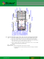
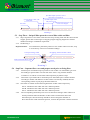
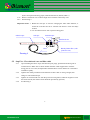
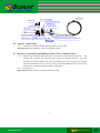
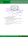
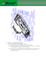
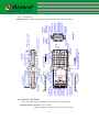
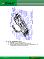
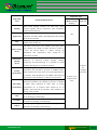
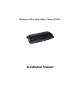
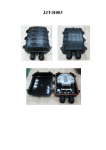
Horizontal Fiber Optic Splice Closure (FOSC)
B1-OPCL12192
Installation Manual
www.bismon.com
BISMON
Datacomms Solutions
1. Scope of application
This Installation Manual suits for the Fiber Optic Splice Closure (Hereafter abbreviated as FOSC), as
the guidance of proper installation.
The scope of application is: aerial, underground, pipeline, handhole. The ambient temperature ranges
from -40 to 65℃.
2. Basic structure and configuration
2.1 Dimension and capacity
Outside dimension (LxWxH)
560x280x180 (mm)
Weight (excluding outside box)
6100g-7500g
Number of inlet/outlet ports
8 (pieces) on each side (total 16 pieces)
Diameter of fiber cable
Φ8—Φ20(mm)
Capacity of FOSC
Bunchy: 12—384 (Cores)
Ribbon: up to 432 (Cores)
2.2 Main components
No.
Name
of
components
Quantity
Usage
Remarks
1
Housing
1 set
Protecting fiber cable splices in
whole
Internal diameter:
480x178 (mm)
2
Insert plate
2 pairs
Fixing the housing
220x80x35(mm)
3
Fiber optic
splice tray
(FOST)
Max. 8 pieces
(bunchy) or6
pieces
(ribbon)
Fixing heat shrinkable protective
sleeve and holding fibers
Suitable for:
Bunchy:12,24,48(cores)
Ribbon:6, (pieces)
4
Fixing bracket
1 set
Fixing fiber cable and reinforced
core
5
Foundation
1 set
Fixing FOST
6
Seal fitting
1 set
Sealing between FOSC cover and
FOSC bottom
7
Port plug
16 pieces
Sealing empty ports
1
www.bismon.com
BISMON
Datacomms Solutions
8
Pressure
1 set
After injecting air, it is used for
pressure testing and sealing
testing
Configuration as per
requirement
1 set
Deriving metallic components of
fiber cable in FOSC for earthing
connection
Configuration as per
requirement
testing valve
9
Earthing
deriving
device
2.3 Main accessories and special tools
No.
Name of accessories
1
Quantity
Usage
Remarks
Heat shrinkable
protective sleeve
Protecting fiber splices
Configuration as per
capacity
2
Nylon tie
Fixing fiber with protective
coat
Configuration as per
capacity
3
Insulation tape
1 roll
Enlarging diameter of fiber
cable for easy fixing
4
Seal tape
1 roll
Enlarging diameter of fiber
cable which fits in with seal
fitting
5
Hanging hook
1 set
For aerial use
6
Earthing wire
1 piece
Putting through between
earthing devices
7
Abrasive cloth
1 piece
Scratching fiber cable
8
Labeling paper
1 piece
Labeling fiber
9
Special wrench
3 pieces
Fixing bolts, tightening nut of
reinforced core
10
Measuring paper
1 piece
To measure perimeter, of
which the diameter of fiber
cable is enlarged with seal tape
To measure perimeter
with the corresponding
measuring paper
11
Buffer tube
decided by
customers
Hitched to fibers and fixed
with FOST, managing buffer
Configuration as per
requirement
12
Desiccant
1 bag
Put into FOSC before sealing
for desiccating air.
13
Rubber hammer
1piece
Knocking in or knocking out
inset plate
Configuration as per
specification
To put through as per
actual requirement
2
www.bismon.com
BISMON
Datacomms Solutions
3.
Necessary tools for installation
3.1 Supplementary materials (to be provided by operator)
Name of materials
Usage
Scotch tape
Labeling, temporarily fixing
Ethyl alcohol
Cleaning
Gauze
Cleaning
3.2 Special tools (to be provided by operator)
Name of tools
Usage
Fiber cutter
Cutting off fibers
Fiber stripper
Strip off protective coat of fiber cable
Combo tools
Assembling FOSC
3.3 Universal tools (to be provided by operator)
Name of tools
Usage and specification
Band tape
Measuring fiber cable
Pipe cutter
Cutting fiber cable
Electrical cutter
Take off protective coat of fiber cable
Combination pliers
Cutting off reinforced core
Screwdriver
Crossing/Paralleling screwdriver
Scissor
Waterproof cover
Waterproof, dustproof
Metal wrench
Tightening nut of reinforced core
3.4
Splicing and testing instruments (to be provided by operator)
Name of instruments
Usage and specification
Fusion Splicing Machine
Fiber splicing
OT DR
Splicing testing
3
www.bismon.com
BISMON
Datacomms Solutions
Provisional splicing tools
Provisional testing
Notice: The above-mentioned tools and testing instruments should be provided by the operators
themselves.
4.
Installation flow chart
1. Open the closure
2. Determine length of fiber cable to be fixed and stripped inside
3. Strip off protective coats of fiber cable and fiber
4. Separate fiber cores and prepare work prior to fixing fiber cable
5. Fix reinforced core and fiber cable
6. Splice fibers
7. Install heat shrinkable protective sleeve and house fibers
8. Check up comprehensively
9. Assemble FOSC housing
4
www.bismon.com
BISMON
Datacomms Solutions
10.Fix FOSC
5. The process of installing FOSC
5.1
Step One - Open the closure
5.1.1
Cleaning the locale and determine where to install the FOSC and then place
fiber cables required.
5.1.2 Check whether the main components and accessories have been well prepared
inside the package.
5.1.3 Open the closure
①. Demount the fixing bolt of insert plate with a special wrench. Knocking the inserts
plates out with rubber hammer or put the fixing bolt into the hole with screw thread
next to the fixing hole of the insert plate and push the insert plates out with the
wrench.
② Use the special wrench to demount all the locating bolts on the housing as well as
fixing bolts (it is also possible to install hanging hook according to the installation
requirement) at four corners, then succeed in opening the closure.
5.1.4
See Drawing 1
Important issues: If the weather condition is not good enough, then a tent must be pitched
for waterproof and dustproof.
5
www.bismon.com
BISMON
Datacomms Solutions
Locating bolt
Cover for seal
fitting
Port plug A
Port plug B
Insert plate
Clasp Foundation
Fixing device
for fiber cable
Fixing bolt
Fixing bolt
Fixing device for
FOSC bottom
reinforced core
Integrated seal fitting Panel
Drawing 1
Bolt for insert plate
Insert plate
Fixing bolt
Locating
bolt
Fixing bolt
Insert plate
FOSC cover
FOST cover
Fixing bolt
Earthing device
Port plug C
Bolt for insert plate
Insert plate
Fixing bracket
5.2 Step Two -Determine length of fiber cable to be fixed and stripped inside FOSC
5.2.1
①. Fiber cable in 80mm length: the distance from seal fitting to fiber cable pressboard
②. Fiber cable in 2150mm length: it is used to be winded and spliced after stripping.
③. Fiber with protective coat in 550mm length: the distance from the fixing point of
fiber cable to the fixing point of FOST (fiber optic splice tray).
④. Fiber in 1600mm length: after stripping off the protective coat, it is to be winded
inside the FOST after splicing with other fibers
5.2.2 See Drawing 2
Important issues: 1. Reserve enough length of fiber cable to be spliced.
2. Stripping length also could be decided by customer according to installation
requirement.
6
www.bismon.com
BISMON
Datacomms Solutions
②.2150mm length of protective coat of
fiber cable to be stripped off
①. Fixing length of fiber cable
inside FOSC
Fiber cable
80mm
③.550mm length of fiber
with protective coat
④.1600mm length of protective coat
of fiber to be stripped
Drawing 2
5.3
Step Three – Strip off fiber protective coat of fiber cable and fiber
5.3.1
Strip off protective coat of fiber cable from the temp. locating mark with the cutter and the
stripper, please refer to Drawing 2 for stripping length. Stripping length also could be
decided according to installation requirement
5.3.2 See Drawing 3.
Important issues: If it is difficult to pull all the protective coat of fiber cable at one time, strip
it off section by section to avoid fiber breakage.
Stripping term inal fiber cable
T em p locating m ark
Inlet term inal fiber cable
C utter
D raw ing 3
5.4
Step Four – Separate fiber cores and prepare work prior to fixing fiber.
5.4.1
5.4.2
5.4.3
5.4.4
Wind 2 layers of insulation tape on protective coat of fiber core. Meanwhile, get rid of
the stuffing to separate fiber core and clean them. Form a ring with the diameter
of 100mm or so and fix it on the fiber cable temporarily by adhesive tape.
This FOSC is provided with 16 inlet/outlet ports. Inlet/outlet ports could be decided
according to number and diameters of fiber cables to be actually installed, then the
corresponding number of port plugs should be taken out.
This FOSC is suitable for the following diameters of fiber cables respectively:
Port A: suitable for fiber cable with max. diameter ф20mm
Port B: suitable for fiber cable with max. diameter ф16mm
Port C: suitable for fiber cable with max. diameter ф14mm
The corresponding inlet/outlet ports are to be selected according to fiber cables to be
actually installed. When the diameter of fiber cable is smaller than that of the
inlet/outlet port, then the seal tape should be used to enlarge the diameter of
fiber cable at fiber cable inlet/outlet position, of which the perimeter could be measured
7
www.bismon.com
BISMON
Datacomms Solutions
by the correspond measuring paper (marked with Hole A, Hole B, Hole C).
5.4.5 Reserve reinforced core in 50mm length and cut off the unnecessary ones.
5.4.6 See Drawing 4
Important Issues: 1. Before the seal tape is used for enlarging the fiber cable diameter, it
should be scratched and to be cleaned with abrasive cloth and ethyl
alcohol.
2. Cut off reinforced core with a special cutting plier.
Adhesive tape
Seal tape
Insulation tape
5~10mm
50mm
15
30
Reinforced core
20 15
Fiber
Bunchy/ribbon fiber (with
protective coat)
Drawing 4
5.5
Step Five - Fix reinforced core and fiber cable
5.5.1
5.5.2
5.5.3
5.5.4
Upon finishing the above steps, then demount port plugs, pressboard and fixing nut of
reinforced core. Make sure to check whether the fiber cable stripped fits in with the
fixing ports or not. If not, the adjustment should be done in time. Otherwise it will affect
installation quality.
Tighten fiber cable pressboard. If the diameter of fiber cable is not big enough, then
enlarge it with insulation tape.
Tighten nut of reinforced core with the special wrench (plastic) and then retighten it with
the metal wrench.(the metal wrench should be provided by operator).
See Drawing 5
8
www.bismon.com
BISMON
Datacomms Solutions
Adhesive tape
Cover for seal fitting
FOSC cover
Fixing bolt for fiber cable
Insulation tape
Seal tape
Reinforced core
Fiber cable
Integrated seal fitting
Fixing device for reinforced core
FOSC bottom
Fixing device of fiber cable
Bunchy/ribbon fiber(with protective coat)
Drawing 5
5.6
Step Six - Splice fibers
5.6.1 Follow user manual of fusion splicing machine to splice fiber.
Important issue: pay attention to the twist and bend of fiber.
5.7 Step Seven -Install heat shrinkable protective sleeve and house fibers
5.7.1
When having completed splicing the fibers, the first fiber ring should be housed on
the
farthest side of FOST, the remaining fiber should be winded, forming a ring with
diameter not less than 80mm. then put it into FOST (Fiber Optic Splice Tray) together
with heat shrinkable protective sleeve.( Firstly fix heat shrinkable protective sleeve into
the slot, then enlarge the diameter of fiber ring properly.)
5.7.2 see Drawing 6
Important issue: pay attentio to the twist and bend of fiber.
9
www.bismon.com
BISMON
Datacomms Solutions
FOST
Left terminal fiber
with protective coat
Right terminal fiber
with protective coat
Fixing slot of heat shrinkable
protective sleeve (bunchy)
Nylon tie
Fixing slot of heat shrinkable
protective sleeve (ribbon)
Grommet
Fiber
Drawing 6
Heat shrinkable protective sleeve
5.8 Step Eight - Check up comprehensively
To ensure the technical requirements, the following instructions must be followed:
5.8.1 The fibers in the FOST are spliced and installed orderly. The curved diameter
of fiber meets with the technical requirements.
5.8.2 The internal tighteners are tightened.
5.8.3 The inlet/outlet ports without fiber cables installed must be blocked up with the port
plugs.
5.8.4 Control the amount of seal tape within a proper range.
5.8.5 Seal fitting is installed neatly and smoothly. If not, level it up with seal tape.
5.8.6 Seal the cover of seal fitting
5.8.7 See Drawing 7
10
www.bismon.com
BISMON
Datacomms Solutions
5.9 Step Nine – Assemble FOSC housing
5.9.1
5.9.2
5.9.3
5.9.4
Put the FOSC cover on the FOSC bottom directly.
Insert locating bolt of FOSC and tighten it with the special wrench.
Insert plate installation method: buckle in the insert plates then knock in the insert plates
with rubber hammer, then tighten the bolts of insert plates.
If the FOSC is for aerial application, then put the hanging hook on one side of the closure
and then tighten fixing bolts on both sides. Otherwise tighten the four fixing bolts on
four corners respectively.
11
Port plug A
Terminal A fiber
cable(port A)
Terminal A fiber
cable(port B)
Port plug B
Port plug C
Fixing bracket
Clasp
Foundation
Panel
Reinforced core
Insulation tape
Terminal A fiber
cable(port C)
Drawing 7
Nylon tie
FOST
Heat shrinkable
protective sleeve
Fixing device for
reinforced core
Earthing device
Reinforced core
Fixing bolt for
fiber cable
Fixing device for
fiber cable
Insulation tape
Seal tape
Terminal B fiber
Port plug A cable(port B)
Terminal B fiber
cable(port C)
Port plug B
Port plug C
Fixing device for reinforced core
Fiber with protective coat
Integrated seal fitting
Grommet
Fiber
Clasp
Terminal A fiber with
protective coat
Nylon tie
Seal tape
Fixing slot of heat
shrinkable protective sleeve
Terminal B fiber with
protective coat
FOST cover
Grommet
FOST
12
FOST co ver
FOSC bottom
Cla sp Foundation
Insert plate
FOSC bo ttom
5.10 Step Ten - Fix FOSC .
5.10.1 Fixing the FOSC and tighten bolts in sequence as per drawing 9.
Important issues: Retighten in five minutes
Tighten properly to avoid the closure to be out of shape.
Insert plate
Panel
Fix ing device for
reinforced core Integ ra ted seal fitting
Fix ing bolt
Cover for
sea l fitting
Port plug A
Port plug B
Port plug C
Earthing device
Fix ing bracket
Insert plate
Fix ing bo lt (at 4 corners)
Fix ing bolt
Fix ing slot for
hanging hook
Inlet/o utlet port C
Inlet/o utlet po rt A
Inlet/o utlet po rt B
Inlet/o utlet po rt B
Inlet/outlet po rt C
Insert plate
Demounting
hole with
female thread
o n insert pla te
Drawing 8
Insert plate
Locating
bolt
Fix ing bolt
Locking hole
with female
threa d on
insert pla te
Earthing deriving device
Insert plate
Insert plate
FOSC co ver
Bolt fo r insert plate
Bolt of insert plate
Insert plate
Bolt fo r insert plate
Fix ing po sition of insert plate
Pressure testing vale
FOSC co ver
Loca ting bolt
5.9.5 See drawing 8
Important issues: cleaning the housing and pay attention to the above sequence.
5.9 Step Nine – Assemble FOSC housing
5.9.1
5.9.2
5.9.3
5.9.4
www.bismon.com
Put the FOSC cover on the FOSC bottom directly.
Insert locating bolt of FOSC and tighten it with the special wrench.
Insert plate installation method: buckle in the insert plates then knock in the insert plates
with rubber hammer, then tighten the bolts of insert plates.
If the FOSC is for aerial application, then put the hanging hook on one side of the closure
and then tighten fixing bolts on both sides. Otherwise tighten the four fixing bolts on
four corners respectively.
11
BISMON
Datacomms Solutions
Port plug A
Terminal A fiber
cable(port A)
Terminal A fiber
cable(port B)
Port plug B
Port plug C
Fixing bracket
Clasp
Foundation
Panel
Reinforced core
Insulation tape
Terminal A fiber
cable(port C)
Drawing 7
Nylon tie
FOST
Heat shrinkable
protective sleeve
Fixing device for
reinforced core
Earthing device
Reinforced core
Fixing bolt for
fiber cable
Fixing device for
fiber cable
Insulation tape
Seal tape
Terminal B fiber
Port plug A cable(port B)
Terminal B fiber
cable(port C)
Port plug B
Port plug C
Fixing device for reinforced core
Fiber with protective coat
Integrated seal fitting
Grommet
Fiber
Clasp
Terminal A fiber with
protective coat
Nylon tie
Seal tape
Fixing slot of heat
shrinkable protective sleeve
Terminal B fiber with
protective coat
FOST cover
Grommet
FOST
Inspecting type
Inspecting
item
Technical Requirements
Package
Each small package contains one fiber optic splice
closure, together with its accessories, tools, installation
manual and packing list.
Appearance
Intact in shape, no burrs, bubbles, chaps, pores, warps,
impurities and other defects, all background colors should
be even and continual.
Sign
There is a clear sign on the housing, such as name and
model of the product, etc.
Fiber storage
device
The fibers reserved are to be winded in fiber optic splice
tray (FOST), the length of fibers housed in FOST is
>1.6m, the curved radius is >30mm. During the
installation and maintenance, there should be no
attenuation on fibers.
Electrical
jointing
device
Inside FOSC: metallic components of fiber cables has the
functions of electrical putting through, earthing
connection and disconnecting. It is possible to install
earthing deriving device outside the housing
Sealing
performance
After sealing according to the stipulated operation
procedures, the injected air pressure is 100KPa±5Kpa,
when immersed in clean water of normal temperature for
15 minutes, there should be no air bubbles, then observed
for 24 hours, there should be no change of air pressure.
Re-sealing
performance
After reopening and resealing according to the stipulated
operation procedures, the injected air pressure is 100KPa
± 5Kpa, when immersed in clean water of normal
temperature for 15 minutes, there should be no air
bubbles, then observed for 24 hours, there should be no
change of air pressure.
Pull
Bearing pull is ≧ 800N at axle orientation, there should
be no breakage on the housing.
Punching
Bearing pressure of 2000N/10cm for 1 minutes, there
should be no breakage on the housing
Impact
Bearing impact energy of 16N•m, 3 times of impacts there
should be not breakage on the housing
Routine test
(Before leaving
factory)
Type test
full
At least 3
sets
sampled
each time
At least 3 sets
sampled each
time
14
www.bismon.com
BISMON
Datacomms Solutions
Bending
The spot between the FOSC and seal fitting can bear
bending tension of 150N at bending angle of ±450 for 10
circles, there should be no breakage on the housing
Torsion
Bearing torsion 50N•m, 10 circle at torsion angle±900,
There should be no breakage on the housing.
Temperature
circle
Injected air pressure of 60KPa±5 KPa, the temperature
circle ranging from -40℃~+65℃, 10 times of the circular
tests (one circular consists of high temperature for 2 hours
+ indoor temperature for 2 hours + low temperature for 2
hours + indoor temperature for 2 hours ) when the
pressure declines, the amplitude is ≦5Kpa, immerse the
swatch in clean water of normal temperature for 15
minutes, there should be no air bubbles.
Voltage
resistance
strength
After sealing the FOSC according to the stipulated
operation procedures, immerse it in clean water of normal
temperature in 1.5m depth for 24 hours, there should be
no breakdown or arc over between the metallic
components of the FOSC, between metallic components
and the ground at DC 15KV for 1 minutes.
Isolating
resistance
After sealing the FOSC according to stipulated operation
procedure, immerse it in clean water in 1.5m depth for
24h, the isolating resistance between the metallic
components of the FOSC, between the metallic
components and the ground should be ≧ 2×10⁴MΩ.
15
www.bismon.com
BISMON
Datacomms Solutions