1
V10.1 Software Bundle
Release 10.1.1
December 2015
DFTView® User Guide [Release 10.1.1, revision 173]
Source III, Inc.
1
2
Overview............................................................................................................................................5
1.1
Introduction................................................................................................................................5
1.2
System Requirements.................................................................................................................7
1.2.1
Operating System................................................................................................................7
1.2.2
Hardware.............................................................................................................................7
1.3
Supported File Formats..............................................................................................................9
1.4
Installing DFTView..................................................................................................................11
1.4.1
Manual Setup....................................................................................................................11
1.4.2
Base Environment.............................................................................................................11
1.4.3
Waveform Viewer Selection.............................................................................................12
1.4.4
Waveform Viewer “Launch Window”..............................................................................14
1.5
Additional Requirements..........................................................................................................14
1.6
Special Licensing Option.........................................................................................................15
Running DFTView®.........................................................................................................................16
2.1
3
Launching the Application.......................................................................................................16
2.1.1
Command-line Arguments................................................................................................16
2.1.2
Operation..........................................................................................................................20
2.2
DFTView® Demo Mode...........................................................................................................22
2.3
Running in Demo Mode...........................................................................................................23
2.4
Command File..........................................................................................................................24
DFTView® Normal Mode................................................................................................................27
3.1
Overview..................................................................................................................................27
3.2
Source Editor............................................................................................................................28
3.2.1
Editor Tabs........................................................................................................................28
3.2.2
Synchronized Navigation..................................................................................................29
3.2.3
Contextual Menu..............................................................................................................29
Page 1
DFTView® User Guide [Release 10.1.1, revision 173]
3.2.4
3.3
Undo/Redo........................................................................................................................29
Button Controls........................................................................................................................30
3.3.1
Regenerate Display...........................................................................................................30
3.3.2
Adjust Waveform Display.................................................................................................30
3.3.3
Previous Vector.................................................................................................................31
3.3.4
Next Vector.......................................................................................................................31
3.3.5
Adjust Source Display......................................................................................................31
3.3.6
Close Current Tab.............................................................................................................32
3.4
Menu Options...........................................................................................................................33
3.4.1
File Menu..........................................................................................................................33
3.4.1.1
Open..........................................................................................................................33
3.4.1.2
Close.........................................................................................................................38
3.4.1.3
Regenerate Display...................................................................................................38
3.4.1.4
Export Waveform to VCD........................................................................................38
3.4.1.5
Save Source..............................................................................................................38
3.4.2
Edit Menu.........................................................................................................................39
3.4.2.1
Undo/Redo................................................................................................................39
3.4.2.2
Reset Preferences......................................................................................................39
3.4.2.3
Set Font Size.............................................................................................................39
3.4.2.4
Toggle Insert/Overstrike...........................................................................................39
3.4.2.5
Previous Vector.........................................................................................................40
3.4.2.6
Next Vector...............................................................................................................40
3.4.2.7
Go to Line Number / Go to Vector...........................................................................40
3.4.2.8
Go to Time Point.......................................................................................................40
3.4.2.9
Go to Cycle...............................................................................................................41
3.4.2.10
Search.....................................................................................................................41
3.4.2.11
Search/Replace........................................................................................................41
3.4.3
Tools Menu.......................................................................................................................42
3.4.3.1
Compare Files...........................................................................................................42
3.4.3.2
Merge/Split Bidirs in Display...................................................................................42
Page 2
DFTView® User Guide [Release 10.1.1, revision 173]
3.4.4
4
3.4.4.1
Help Browser............................................................................................................42
3.4.4.2
Contextual Help Browser.........................................................................................43
3.5
Error Detection.........................................................................................................................44
3.6
Separating Bidirectional Pins...................................................................................................45
3.6.1
File/Open Dialog..............................................................................................................45
3.6.2
Change via Tools Menu....................................................................................................46
3.6.3
Change via Display Icon...................................................................................................46
3.7
Keyboard Shortcuts..................................................................................................................47
3.8
Disabling Waveform or Source Editor Function......................................................................48
3.8.1
Disabling Waveform.........................................................................................................48
3.8.2
Disabling Source Editing..................................................................................................49
DFTView® V-mode..........................................................................................................................50
4.1
Overview..................................................................................................................................50
4.2
Vertical Search..........................................................................................................................53
4.3
Vertical Search/Replace............................................................................................................53
4.4
Locate Pin/Signal.....................................................................................................................54
4.5
Smash and Compress................................................................................................................55
4.6
Other Operations......................................................................................................................56
4.7
Pin Selection and Formatting...................................................................................................57
4.7.1
Basic File Format..............................................................................................................57
4.7.2
Named Pin Groups............................................................................................................58
4.7.3
Single-bit Buses As Pin Groups........................................................................................59
4.7.4
Display Radix...................................................................................................................59
4.7.5
Declaring Duplicate Pins..................................................................................................62
4.8
5
Help Menu........................................................................................................................42
Editing Columns When Formatted...........................................................................................63
DFTView® Compare Mode..............................................................................................................65
5.1
Overview..................................................................................................................................65
5.2
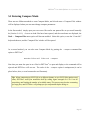
Entering Compare Mode..........................................................................................................67
5.3
Compare Files Window............................................................................................................68
Page 3
DFTView® User Guide [Release 10.1.1, revision 173]
5.3.1
File Selection....................................................................................................................69
5.3.2
Compare Options..............................................................................................................70
5.3.2.1
Compare Mode.........................................................................................................70
5.3.2.2
Check Signals...........................................................................................................73
5.3.2.3
Compare Window.....................................................................................................73
5.3.2.4
Compare Range........................................................................................................74
5.3.2.5
Ignore Miscompares When.......................................................................................74
5.3.2.6
Compare Results Format..........................................................................................76
5.3.3
5.3.3.1
Signal List.................................................................................................................78
5.3.3.2
Filter (regex).............................................................................................................78
5.3.3.3
Direction Editor........................................................................................................79
5.3.3.4
Signals to Include.....................................................................................................79
5.3.3.5
Predefined Groups....................................................................................................80
5.3.4
5.4
Signal Browser.................................................................................................................77
Controls............................................................................................................................80
Compare Results Tab................................................................................................................80
5.4.1
Regenerate Comparison....................................................................................................83
5.4.2
Previous Miscompare.......................................................................................................83
5.4.3
Next Miscompare..............................................................................................................83
5.4.4
Sync to Waveform Cursor.................................................................................................84
5.4.5
Close Current Tab.............................................................................................................84
Page 4
DFTView® User Guide [Release 10.1.1, revision 173]
1 OVERVIEW
1.1 Introduction
The DFTView® program allows the user to view and edit source files in a number of formats including
WGL, STIL, Catalyst, SVF, Advantest T2000 and VCD/EVCD, or VTRAN ®-generated Verigy 93000
or Teradyne J750 or FLEX formats, in a text editor window while viewing the waveforms represented
by the source file timing and vectors in a Synopsys nWave or a GTKWave window. It provides the
following capabilities:
•
Directly view the waveforms that will be applied to a device on a tester as described in a WGL,
STIL, Catalyst, SVF, Advantest T2000, VCD/EVCD file or a VTRAN ®-generated Verigy 93000
or Teradyne J750 or FLEX test vector file.
•
Waveform viewing of these files provides exact state as well as edge timing information for the
test program in a very familiar and graphical format.
•
Automatically check a source file for syntax errors, and validate by inspection a source file’s
contents prior to the test vectors being applied to a device on the tester.
•
Edit the contents of the source file and see the exact effect on tester waveforms. This is a
common situation for debug and SOC integration.
•
Some testers directly accept STIL files as test programs so this allows the user to directly view
and validate these test patterns.
•
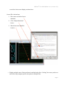
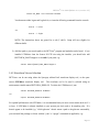
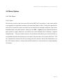
Select a vector line in the source file with your cursor, click the “Adjust Waveform Display”
button and see the exact corresponding waveform location in the waveform display window. Or
select a waveform position and click “Adjust Source Display” to see the corresponding source
Page 5
DFTView® User Guide [Release 10.1.1, revision 173]
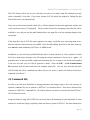
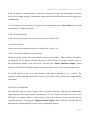
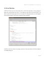
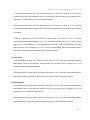
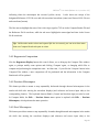
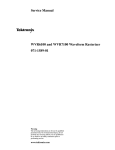
vector line in the source display as shown here:
Source File to Waveform:
1. Place cursor on desired vector
statement
2. Click “Adjust Waveform”
button
3. Waveform cursor identifies
location
•
Display multiple source files/waveforms in multiple tabs; allow “locking” the cursor position on
each tab to help compare specific time points in multiple files.
Page 6
DFTView® User Guide [Release 10.1.1, revision 173]
•
Compare the waveforms of two disparate files types (for example STIL and VCD) to quickly
identify differences in waveforms, such as when comparing input and output files from a vector
translation (e.g. a VTRAN® translation)
1.2 System Requirements
1.2.1 Operating System
DFTView® binaries are available for 32-bit and 64-bit Linux with a 2.4.21 or higher kernel and should
run on most Linux distributions released within the last 10 years. Some of the distributions (both 32-bit
and 64-bit) DFTView® has been validated on include:
•
Fedora 14, Fedora 15, Fedora 16
•
CentOS 3.8, CentOS 5.6
•
openSUSE 12.3
•
Ubuntu 10.04/10, Ubuntu 11.04/10, Ubuntu 12.04
DFTView® is also available for 32-bit and 64-bit Solaris (SPARC) 8 or higher, and has been validated
on Solaris 8 and Solaris 10.
1.2.2 Hardware
DFTView® for Linux runs on Intel x86 (32-bit) and AMD64/EM64T (64-bit) processors. DFTView®
for Solaris run on 32-bit and 64-bit SPARC processors.
DFTView® requires up to 200MB of memory for each tab you have open, and be aware that if you open
large input files this requirement goes up accordingly. For example, on an AMD64 test system, when
opening a single 163MB STIL file containing a lot of repeat vectors, DFTView ® required at its peak
1.4GB of physical RAM. It also consumed over 4GB of storage (hard disk space) for intermediate
(temporary) vector data.
Page 7
DFTView® User Guide [Release 10.1.1, revision 173]
The complete DFTView® package requires approximately 24MB of hard drive (storage) space to
install. You should also factor in the memory and storage space requirements for your chosen
waveform viewer (Section 1.4.3); consult the relevant documentation of each package to get more
information.
Temporary files created during normal operation of DFTView® can be very large (depending on input
file size, number of vectors and other considerations); a good rule of thumb is to ensure at least 30
times the (uncompressed) storage space required for an ATE file – for example you might need 3GB or
more of space when opening a 100MB file (see example above).
DFTView® requires a display resolution of, at an absolute minimum, 1024×768 pixels (XGA).
However for optimum results we recommend a display resolution of at least 1280×1024 pixels
(SXGA).
Page 8
DFTView® User Guide [Release 10.1.1, revision 173]
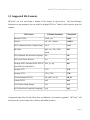
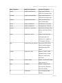
1.3 Supported File Formats
DFTView® can read and display a number of file formats as shown below. The listed filename
extensions are not mandatory, but are useful in helping DFTView® identify which format a given file
contains.
File Format
Filename Extensions
Shorthand
Advantest T2000
.t2000, .pat
t2000
Catalyst
.cat, .catl, .catalyst
catalyst
EVCD (Enhanced Value Change Dump)
.evcd
evcd
HP 93000
.agk, .avc, .93k, .v93k,
93k
.hptab
STIL (Standard Test Interface Language) .stil
stil
SVF (Serial Vector Format)
svf
.svf
Teradyne FLEX (includes FLEX, iFLEX, .flex, .tp, .atp
flex
microFLEX and ultraFLEX)
Teradyne J750
.j750
j750
Teradyne J750+
.j750, .j750+
j750+
Texas Instruments TDL 91
.tdl, .tdl91, .tdl_91
tdl_91
Toshiba TSTL2
.tstl2
tstl2
VCD (Value Change Dump)
.vcd
vcd
WGL (Waveform Generation Language)
.wgl
wgl
Compressed input files will also likely have an additional '.gz' extension appended. DFTView ® will
auto-detect the correct format with or without this added extension.
Page 9
DFTView® User Guide [Release 10.1.1, revision 173]
If you wish to read a supported input file which has a different or custom extension you can tell
DFTView® what the file format is by passing a -FMT or --format=FMT command-line argument,
substituting FMT with the relevant shorthand format string above (see Section 2.1.1).
Tip: While DFTView® can view any WGL, STIL, EVCD or VCD file, for other ATE formats it
can only read VTRAN-generated files.
Page 10
DFTView® User Guide [Release 10.1.1, revision 173]
1.4 Installing DFTView
Refer to the separate Installation Guide included with the Source III V10.1 Software Bundle for
information on installing, upgrading and uninstalling DFTView® along with details on licensing.
1.4.1 Manual Setup
The DFTView® program bundles are available for Solaris SPARC and Linux platforms. These can be
downloaded from the Source III web site at:
http://www.sourceiii.com/support.php
For normal use we highly recommend that the bundled installer S3install.sh be used to install and
configure your software, including all required environment variables.
Consult the separate
Installation Guide included with the Source III V10.1 Software Bundle.
1.4.2 Base Environment
If you elect to manually install DFTView® the following environment variables will be needed:
1) Define an environment variable named S3_ROOT which points to the installed directory – this
assumes that VTRAN® has already been installed there (DFTView® shares some of the
executables included in VTRAN®). In order to set the S3_ROOT environment variable, add the
following command to your .cshrc and/or .login file:
setenv S3_ROOT /path
where /path is the directory path into which this software was loaded. For example, if the tar
file for the linux64 build was unpacked in the directory /usr/source3, then the following
command could be used:
Page 11
DFTView® User Guide [Release 10.1.1, revision 173]
setenv S3_ROOT /usr/source3/linux64
You then must either logout and log back in, or issue the following command from the console:
source ~/.cshrc
-orsource ~/.login
NOTE: The instructions above are geared for a csh (C shell). Setup will vary slightly for
different shells.
2) Add the /path to your search path so the DFTView ® program and modules can be found. If you
installed GTKWave from the Source III FTP site using the installer, you should also add
$DFTVIEW_ROOT/support/ to the end of your path, e.g.:
setenv PATH ${PATH}:$S3_ROOT/support
1.4.3 Waveform Viewer Selection
DFTView® can be run using either the Synopsys nWave/Verdi waveform display tool, or the opensource GTKWave waveform display tool.
The waveform tool to be used is selected using an
environment variable named DFTVIEW_DISPLAY. To select the GTKWave tool, use:
setenv DFTVIEW_DISPLAY GTKWave
-orexport DFTVIEW_DISPLAY=GTKWave
For optimal performance with GTKWave, it is recommended that you use a recent release such as v3.3
or later. If GTKWave is already installed on your system you don't need to do anything else. If it
doesn't appear to be installed (e.g. "which gtkwave" doesn't return a path to the gtkwave executable),
you can install the package on Linux with the "yum" or "apt-get" commands as applicable, e.g.:
Page 12
DFTView® User Guide [Release 10.1.1, revision 173]
RedHat, CentOS, Fedora, etc.:
sudo yum install gtkwave
Ubuntu, Debian, etc:
sudo apt-get install gtkwave
We have also prepared Linux and Solaris-compatible GTKWave binary packages (release 3.3.21)
which are freely available from our support FTP site.
Installation is as simple as running the
S3install.sh script as described in the separate Installation Guide, or downloading the relevant
package compatible with your system, unpacking it and adding the path to the "gtkwave" command to
your PATH. At this stage you can verify GTKWave is working just by typing the command "gtkwave".
To select the Synopsys nWave waveform display tool, use:
setenv DFTVIEW_DISPLAY nWave
-orexport DFTVIEW_DISPLAY=nWave
If no DFTVIEW_DISPLAY environment variable is defined, then the Synopsys nWave tool is
assumed. When the nWave tool is being used to display waveforms, by default, DFTView ® launches
nWave directly. However, for some customer environments it is necessary to launch Verdi first and
then bring-up nWave from Verdi.
In order to address this, an environment variable named
DFTV_VERDI can be defined and set to a 1, which will cause Verdi to be launched prior to nWave. To
activate this, use:
setenv DFTV_VERDI 1
-orexport DFTV_VERDI=1
Tip: Users of older versions of DFTView ® may notice that in the past, the waveform viewer
would be launched immediately when DFTView® was run, even without arguments. With the
tab-based viewing system which was first introduced in DFTView ® 3, you will not see the
waveform viewer application launch until an input file is opened.
Page 13
DFTView® User Guide [Release 10.1.1, revision 173]
Tip: Also note that the older DFTVIEW_ROOT environment variable is no longer required
and is typically ignored.
1.4.4 Waveform Viewer “Launch Window”
By default DFTView® will wait up to 90 seconds after first launching your chosen waveform viewer
application. If after this 90 seconds the viewer has not entered a ready state it has most likely hung
during launch, and DFTView® will report the issue. If it cannot recover at this stage DFTView ® will
exit. In the unlikely event that 90 seconds isn't sufficient for your viewer to launch, you may increase
this wait time from 90 seconds by using the --timeout command-line option (Section 2.1.1); for
example to allow a 5 minute (!) grace period for your viewer to launch, you would enter:
DFTView --timeout 300 ...
1.5 Additional Requirements
To run DFTView® your system must also have the following:
•
If using nWave, a Synopsys Verdi license must be available, and the “nWave” and/or “Verdi”
commands must be in your path, as well as the “vfast” utility (also shipped as part of the Verdi
system)
•
If using GTKWave, the “gtkwave” program must be in your path
Many Linux distributions include GTKWave by default, and in most cases this option is recommended
(if the command “which gtkwave” returns the path to the gtkwave binary, you're all set). However with
some Linux distributions GTKWave is not automatically installed, and if your system does not have
GTKWave already we recommend that you run the installer (Section 1.4) and allow it to download a
compatible version for you.
Page 14
DFTView® User Guide [Release 10.1.1, revision 173]
Note: We have identified an issue with GTKWave 3.3.34 on Ubuntu 12.04, where the binary is
compiled with a debug library called JUDYMEM.
This unfortunately will interfere with
DFTView®/GTKWave communication. While we have so far only encountered this issue on one Linux
distribution, it may exist on others so again we recommend that you run the installer which will detect
GTKWave binaries which may present this problem and alert you before automatically downloading a
compatible version directly from Source III.
Once the above setup steps have been performed, you should be able to go to any working directory
and run DFTView® on your WGL, STIL, Catalyst, SVF, Advantest T2000, VCD/EVCD and VTRAN ®generated Verigy 93000, Teradyne J750 and FLEX files.
1.6 Special Licensing Option
While individual licneses are available for both VTRAN ® and DFTView®, customers who opt for
counted VTRAN® license subscriptions (floating or server-managed node-locked) automatically gain
DFTView® access as well. DFTView® will attempt to check out a valid VTRAN® license if no separate
dedicated license is available – your license server log will show that a VTRAN ® license checked out,
but an extra notation will follow to indicate that the DFTView® tool has checked out the license.
Page 15
DFTView® User Guide [Release 10.1.1, revision 173]
2 RUNNING DFTVIEW
®
2.1 Launching the Application
The simplest way to invoke DFTView® is to simply launch it without any arguments:
DFTView
This will bring-up an empty waveform and DFTView® source window. From here, you can use the
File → Open operation from the main menu to load a new file.
See the discussion below for more
details on using this feature.
2.1.1 Command-line Arguments
DFTView® also supports a selection of command-line arguments to allow opening one or more files
with certain options enabled. For example if you pass the names of several files at once each one will
be opened in a separate tab, e.g.:
DFTView project1.stil project2.stil project2a.vcd
As you can see from this example, all files do not need to be the same format, for each file the format is
determined automatically where possible. If using a file with an unknown extension, you can specify
the format with the short or long-version option as shown here:
DFTView -stil project17.txt
-orDFTView –format=stil project17.txt
Use whichever form of the option you prefer. For all command-line options, the short and long forms
are functionally equivalent, and you can mix and match short and long forms together.
Page 16
DFTView® User Guide [Release 10.1.1, revision 173]
Note that when specifying multiple vector files the format you define will be applied only to the next
input file in the sequence, so it's best to explicitly name every format when passing in multiple vector
files (or use known extensions). Thus the specified order of formats must match the order of input
files, so all of the following examples are equivalent:
DFTView --format=stil STILfile.txt --format=wgl WGLfile.txt
DFTView --format=stil --format=wgl STILfile.txt WGLfile.txt
DFTView STILfile.txt WGLfile.txt --format=stil --format=wgl
A full list of supported formats, known extensions, and the shorthand format name to use on the
command line can be found in the table in section 1.3.
You can also open a series of files with known extensions and then load additional files into new tabs
using the File → Open menu option.
The full list of available command-line options is as follows:
Short Argument
Long-form Argument
Feature Description
-FMT
--format=FMT
Set named input format, e.g.
e.g. -stil
e.g. --format=stil
-stil or --format=stil
Available formats: stil, wgl,
t2000, catalyst, svf, flex,
j750, j750+, tdl_91, tstl2,
93k, vcd, evcd
-cmd
--commandfile
Read instructions from a
command file (section 2.4)
-nobidir
--option=noexplicitbidirs
Disable explicit bidirects
(normally on) (section 3.4.1)
Page 17
DFTView® User Guide [Release 10.1.1, revision 173]
Short Argument
Long-form Argument
Feature Description
-nocell
--option=omitscancell
Omit ScanCell blocks
(STIL/WGL formats only)
-nochain
--option=omitscanchain
Omit ScanChain blocks
(STIL/WGL formats only)
-nostate
--option-omitscanstate
Omit ScanState blocks
(WGL format only)
-start N
--option=starttime N
Set start time to N (in ns)
-stop N
--option=stoptime N
Set stop time to N (in ns)
-nowfm
--option=no_waveform
Load source file only; don't
display waveform (section
3.8.1)
-nosrc
--option=no_source
Display waveform only;
don't load source file
(section 3.8.2 - applies to
VCD and EVCD only)
-epp
--option=evcd_pre_process
Pre-process EVCD files;
slower load but supports
splitting/merging bidir
signals
-noctim
--option=no_ctim
Remove “SQPG CTIM”
statements from V-mode
display (V-mode only)
(section 4)
-vmode
--mode=vmode
Enable V-mode (93K format
only) (section 4)
-cmp
--compare
Enable Compare Mode
(section Error: Reference
source not found)
-lf
--listformats
List all supported input
formats
Page 18
DFTView® User Guide [Release 10.1.1, revision 173]
Short Argument
Long-form Argument
Feature Description
-s
--sync
Enable synced navigation on
all tabs (section 3.2.1)
-t N
--timeout N
Time (in seconds) before
DFTView® reports an error
if the waveform viewer
hasn't reported a ready state
(default: 90 sec) (section
1.4.4)
-h
--help
Show all available options
-id
--hostid
Report FLEXnet host ID
(section 1.4)
-v
--version
Display version number
Note: In Demo mode, all command-line options other than the “List Formats” -lf (--listformats),
“Show help” -h (--help), “Report FLEXnet host ID” -id (--hostid) and “Show version” -v (-version)
options are ignored.
When invoking DFTView® with command-line arguments, you should at a minimum provide the
source filename(s). The syntax is:
DFTView [-wgl|-stil|-93k|etc.] [infile] [timing_file]
Note that when viewing Verigy 93K files, both a vector file (.avc or .hptab) and a timing file (.dvc) is
required if you wish to generate and display a waveform. Likewise for reading a FLEX file, both a
vector file (.atp or .flex) and a timing file are needed. For FLEX, the timing file is a base name.
DFTView® will append the suffix _esets.txt and tsets.txt to the base name to find the edge sets
and time sets FLEX timing files. If you specify a file which normally requires a timing file, but you do
not provide it, of if you use the --option=no_waveform command-line option, DFTView will open the
source file but will not attempt to generate a waveform. You can later click the 'Generate Waveform'
Page 19
DFTView® User Guide [Release 10.1.1, revision 173]
button to display the waveform, and DFTView will prompt you at that time for a timing file, if it needs
one. See Section 3.8.1 for more information.
You can also define input arguments such as filename, start time etc. in an ASCII command file. See
Section Error: Reference source not found for details.
Some command line examples for invoking DFTView® are:
DFTView
DFTView ovf.svf
DFTView -wgl myWglFile
DFTView -stil myStilFile
DFTView --format=wgl ovf.wgl.gz
DFTView -93k maximo.avc maximo.dvc
DFTView --format=93k sample.hptab sample.dvc -vmode
DFTView sample.avc sample.dvc --mode=vmode
DFTView --commandfile input.cmd
DFTView --compare sample.stil sample.vcd'
DFTView -nowfm input.evcd
DFTView --option=no_waveform input.evcd
2.1.2 Operation
DFTView® begins by converting the source file to a waveform viewing file for either nWave or
GTKWave. It then automatically loads the waveforms in the display program (if possible) and all
signals are selected. In addition the contents of the source vector file are loaded in the DFTView ® text
editor. Once the source file is loaded and displayed in the DFTView ® window, you can begin viewing
and editing.
Note that vector files can be gzipped and will be expanded automatically, but timing files (for those
formats that use them) must be provided uncompressed (Section 3.4.1).
Page 20
DFTView® User Guide [Release 10.1.1, revision 173]
You can, if loading 93k format vector and timing files on the command line, also provide an optional
-vmode
(or longer-form --mode=vmode) argument which will put the editor directly into V-mode
(Section 4). The -vmode argument is ignored for other file input formats. As with normal mode, you
can elect to omit the timing file name, and the source file will be opened in V-mode without displaying
the associated waveform.
The nWave or GTKWave window is used to scroll through signals and event times to view the
waveforms. Refer to the Synopsys documentation for using nWave or the documentation for GTKWave
for its use.
Page 21
DFTView® User Guide [Release 10.1.1, revision 173]
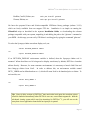
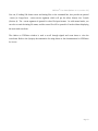
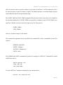
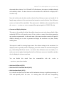
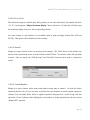
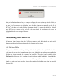
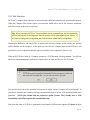
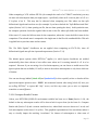
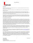
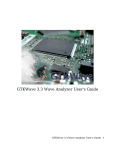
2.2 DFTView® Demo Mode
When you run DFTView®, if you have not purchased a license key or if there is an issue with the
license, a dialog box will appear giving you the option of running in DEMO mode for evaluation, as
shown here:
If this dialog appears and you have purchased a license or have received an evaluation license, you can
select “No” here to exit the application and address whatever license issue you may have – check the
parent terminal window where you launched DFTView® for specific license-related messages.
If you select “Yes”, you will enter DEMO mode. In this mode, DFTView ® will allow you to view and
interact with a set of demo files shipped with the application, but will not allow you to view, edit or
save your own files. Also note that if DFTView® enters DEMO mode, any command line arguments
you may have passed when launching the application (e.g. an input filename or format) will be ignored.
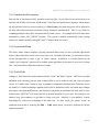
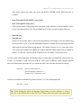
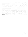
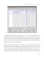
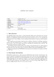
You can always tell if DFTView® is running in DEMO mode – it will be clearly indicated near the
bottom left of each tab in the main application window as shown:
Page 22
DFTView® User Guide [Release 10.1.1, revision 173]
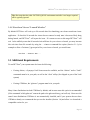
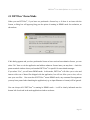
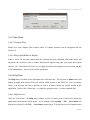
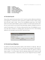
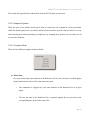
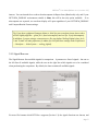
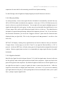
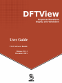
2.3 Running in Demo Mode
As with normal (licensed) mode, you can select File → Open to select an input file. In DEMO mode
however, the file open dialog box will appear slightly different to the regular licensed version, as shown
below – The “Choose” buttons will be disabled and the OVF File Name will not allow you to type in a
filename. Instead, you will be presented with a drop-down list of demo files (which are shipped with
the application and reside in the $DFTVIEW_ROOT/demo/ directory). Other options such as Omitting
ScanCell and ScanChain blocks, start and stop time etc. are available if you wish to try them out.
Page 23
DFTView® User Guide [Release 10.1.1, revision 173]
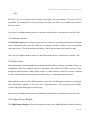
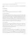
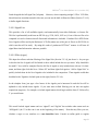
The OVF Format will be set for you each time you select a new demo input file, although you may
select it manually if you wish. If you select a demo OVF file which also requires a Timing file, that
field will be set for you automatically.
Once you've selected and opened a demo file, it will be displayed in the main application window and
in the waveform viewer (if configured). All the normal controls for navigating around the file will be
available to you, and you can also make limited edits to the input file to see the resulting changes in the
waveforms.
If the drop-down list of OVF file names appears to be empty, verify that your $DFTVIEW_ROOT/demo/
directory and the contents therein are readable. Also note that adding other files to the demo directory
does not make them readable by DFTView® in DEMO mode.
In addition, you can view the provided 93k demo files in V-mode (Section 4). Once opened in V-mode
feel free to make minor changes to the file using the various operations in Section 4 as a guide. Of
particular note, we have provided a sample pin-formatting file sbc.example.fmt which can be applied
to the sbc2.avc and sbv2.dvc files if opened in V-mode. Select the Edit → Load V-mode format
file operation from the menu and select the example format file. You can view and edit this plain
ASCII format text file in a standard text editor such as vim, nedit or emacs; the format of this file is
explained in Section 4.7.
2.4 Command File
In order to provide more flexibility in passing parameters and using scripts to drive the viewing, an
optional command file can be passed to DFTView® as described above. This section discusses the
contents of a DFTView® command file. All of these features can also be accessed from the DFTView ®
GUI in interactive mode.
Long load times for large WGL/STIL files can occur due to the flattening of cycle-based files to event
streams for waveform display, especially when scan data is present. DFTView ® has been enhanced to
Page 24
DFTView® User Guide [Release 10.1.1, revision 173]
allow the user the option to specify a subset of cycle times. In the future, it will be enhanced to allow
the user the option to specify a subset of signals. The Reader generates a waveform display file that
only includes the data for the specified time range.
The START_TIME and STOP_TIME commands define the first and last event times to be included in
the waveform display file. If START_TIME is not specified, it defaults to 0ns. If STOP_TIME is not
specified, it defaults to the last event in the input vector file. The syntax is:
START_TIME n;
STOP_TIME n;
where n is a positive integer or real number.
The command line arguments also are specified in the command file, when a command file is used. The
syntax is:
FORMAT wgl|stil|93k;
INFILE <filename>;
AUXFILE <filename.dvc>;
UNITS <units>;
The FORMAT and UNITS commands are optional. An example of a DFTView ® command file, named
runDFTview.cmd, is:
INFILE myDesign.stil;
START_TIME 100;
STOP_TIME 50000;
To invoke DFTView® using this command file, the command line is:
DFTView -cmd runDFTview.cmd
Page 25
DFTView® User Guide [Release 10.1.1, revision 173]
-orDFTView --commandfile runDFTView.cmd
(note that the short- and long-form arguments are functionally equivalent).
The waveform file created by the DFTView® in this example will only contain events from the STIL
file starting at 100ns and ending at 50000ns, inclusive.
Note: If you use a command file all other command-line arguments will be ignored to avoid any
conflicting settings.
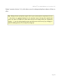
Tip: Loading files which define large numbers of vectors (millions or more) may take a long
time since DFTView® flatten loops and repeats when generating the vectors so that they can
be displayed. We recommend that you avail of the START_TIME and STOP_TIME feature
which allows you to quickly load an area of interest without having to load all vectors. If
you don’t wish to use a command file you can also specify the start and stop times via the
File/Open dialog (see section 3.4.1).
Page 26
DFTView® User Guide [Release 10.1.1, revision 173]
3 DFTVIEW NORMAL MODE
®
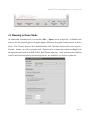
3.1 Overview
When you launch DFTView® you will see a source file editing window and, depending on which
waveform application you configured, a waveform viewer window – a separate application which
DFTView® will launch on your behalf. The main source editing window contains a number of menu
operations as well as one or more tabs, each with a control panel of buttons on the bottom. In summary
these operations and controls are:
-
Control Panel Buttons:
Regenerate Display (button)
Adjust Waveform Display (button)
Previous Vector (button)
Next Vector (button)
Adjust Source Display (button)
Close Current Tab (button)
-
File (drop-down menu):
File → Open
File → Close
File → Regenerate Display
File → Export Waveform to VCD
File → Save Source
File → Exit
-
Edit (drop-down menu):
Edit → Undo
Edit → Redo
Edit → Search
Edit → Search/Replace
Edit → Reset Preferences
Edit → Set Font Size
Edit → Toggle Insert/Overstrike
Edit → Previous Vector
Edit → Next Vector
Edit → Go To Line Number
Edit → Go to Time Point
Edit → Go to Cycle
Page 27
DFTView® User Guide [Release 10.1.1, revision 173]
-
Tools (drop-down menu):
Tools → Compare Files
Tools → Merge/Split Bidirs in Display
Tools → Apply New Timing File(s)
-
Help (drop-down menu):
Help → About
Help → Context-Sensitive Help
Help → File → selection
Help → Edit → selection
Help → Tools → selection
Help → V-mode → selection
Help → Buttons → selection
3.2 Source Editor
The main portion of the DFTView® display window is the text editor itself. You can make edits to your
source and then click the Regenerate Display button to see how your edit will affect the waveform
(Section 3.3.1). You can also elect to save your modified source (Section 3.4.1). Note that for some
formats, especially those which require a separate timing file, edits which add new signals are not
recommended, and in fact may cause DFTView® to detect these additions as errors.
3.2.1 Editor Tabs
Multiple separate source files can be loaded into separate tabs, and a new tab will be automatically
created for each file you open. In addition, the new waveform will be displayed in a separate pane or
window in your chosen waveform viewer.
You can switch between tabs by simply clicking on the name, which will be the open file for that tab.
As you switch tabs, focus will automatically also switch in the waveform viewer window or pane.
Any time you close a file that tab (and the associated waveform view) will be closed. Tabs provide a
convenient way for viewing multiple input files.
Page 28
DFTView® User Guide [Release 10.1.1, revision 173]
3.2.2 Synchronized Navigation
Each tab has a “Synchronize Tabs” checkbox at the top right. At any time you can check this box (in
any tab) and all tabs will become synchronized. Now when you perform any operation which adjusts
the selected time point in a source window (e.g. Next Vector), the same time point will be selected in
all other tabs (and associated waveforms viewers windows) simultaneously. This is very useful for
comparing multiple source files which describe the same vectors – for example files which have been
translated by Source III's VTRAN ® software. This option is enabled automatically when viewing
results of a compare operation using DFTView® Compare Mode (Section 5).
3.2.3 Contextual Menu
The source editor window displays a pop-up contextual menu when you click with the right mouse
button, and provides short-cut access to some basic tools. In normal edit mode, you can select a section
of text and right-click to select “copy” or “paste” options. In addition, in V-mode (Section 4) the
“smash” and “compress” options will be enabled where applicable (if the cursor is on a loop or repeat
line – see Section Error: Reference source not found).
3.2.4 Undo/Redo
Changes to your source file can be undone with the “Undo” and “Redo” options. DFTView ® provides
unlimited undo (meaning you can undo as many edits as you've made) in each tab, with one major
caveat. In V-mode when a repeat or loop is smashed or compressed (Section Error: Reference source
not found) or V-mode formatting is applied (Section Error: Reference source not found) these changes
also require other data modifications, and after these operations are performed the undo stack is reset.
In these cases, DFTView® will always provide an inverse operation for you to use. For example if you
smash a loop, just compress it to get back to where you were. Similarly, if you applied a V-mode
formatting file, remove the formatting in the same way. In other words, you cannot “Undo” an
operation such as this by selecting the Edit → Undo menu option, you need to perform the inverse
operation yourself.
Page 29
DFTView® User Guide [Release 10.1.1, revision 173]
3.3 Button Controls
3.3.1 Regenerate Display
The Regenerate Display button is used to update the data displayed in the waveform window, after
modifying the source file vector or timing data with the DFTView ® editor. This button does NOT
update the original source file specified on the command line or in the command file. In some
circumstances when you make changes to your source file, you may see this button begin to flash. This
occurs as a reminder that the waveform and source files are now possibly out of sync, and you should
click this button once you have completed any additional edits you wish to make. You will usually see
this button flash after you have performed a Smash or Compress operation (Section 4.3).
If you haven't yet generated a waveform (for example you specified no timing file(s) for a format
which requires them, or used the --option=no_waveform command-line option – see Section 3.8.1),
this button will be labeled Generate Display. Conversely if you elected to display a VCD or EVCD
waveform without loading the source file into the editor window (see Section 3.8.2), this button will be
labeled Load Source File.
3.3.2 Adjust Waveform Display
The Adjust Waveform Display button is used to synchronize the waveform display with the
DFTView® source editor display. This can be used in several ways:
•
When clicked on a Procedure Call, Macro, Main Pattern Loop/Repeat, or Main Pattern Scan
statement in the Source Display, causes the waveform viewer and the text editor's cursors to
move to the first cycle of the pattern structure; W and C statements, for example, are skipped.
Repeated clicks act as Next Cycle until the end of the structure. When clicked at the end, causes
a return to first cycle of the pattern structure.
•
When clicked on a Loop or STIL Shift inside a Macro or Procedure, the behavior is the same as
Loop in the Main Pattern, except clicking on last (end) cycle results in falling out of the Loop or
Page 30
DFTView® User Guide [Release 10.1.1, revision 173]
Shift.
DFTView® sets the waveform cursor to adjust the display. Any user setting of the cursor will be
overridden. For a multiple-line vector in the source file editor, the editor's cursor must be set to the first
line of the vector.
This control is disabled when the source file has been loaded without a waveform as in Section 3.8.1).
3.3.3 Previous Vector
The Previous Vector button and menu option provides a means to step sequentially backwards through
vector statements in the source file while also moving the waveform display to the corresponding
waveform location. The keyboard shortcut Ctrl-< (Control and less-than sign) can also be used.
This control is disabled when the source file has been loaded without a waveform as in Section 3.8.1).
3.3.4 Next Vector
Steps sequentially forward through vectors. Repeated clicks before or during a procedure, Macro, or
Loop/Repeat in the Source Display causes the waveform viewer and the text editor's cursors to move
through the pattern structure. When clicked at end of a pattern structure, causes the cursors to advance
to vector related statements following the procedure, macro, or loop/repeat pattern structure.
When clicked on a Scan or STIL Shift statement, causes the Scan/Shift pattern structure to be skipped.
The cursor/marker advances to the next vector related statement. The keyboard shortcut Ctrl->
(Control and greater-than sign) can also be used.
This control is disabled when the source file has been loaded without a waveform as in Section 3.8.1).
3.3.5 Adjust Source Display
The Adjust Source Display performs the opposite function as the Adjust Waveform Display described
Page 31
DFTView® User Guide [Release 10.1.1, revision 173]
above. In this case, the waveform cursor is first placed over a desired location in the waveform
window. Then when the Adjust Source Display button is activated, the cursor in the source file window
is adjusted to display the vector line which generated the waveform at the selected location.
This control is disabled when the source file has been loaded without a waveform as in Section 3.8.1).
3.3.6 Close Current Tab
The Close Current Tab button is used to close the current tab and associated waveform, along with
cleaning up any temporary files associated with it. You do not need to close one tab before opening
another – you can open several files (each in its own tab) and easily switch between them, and you can
also then run DFTView Compare on them (Section 5).
Page 32
DFTView® User Guide [Release 10.1.1, revision 173]
3.4 Menu Options
3.4.1 File Menu
3.4.1.1 Open
This selection is used to load a new source file into the DFTView® text window. It also causes the file
to be mapped to its equivalent waveform in the waveform display window. During this operation the
source file is checked for syntax errors and if any are found an error message is displayed, with a more
detailed message in the parent window. When you select File → Open (or use the keyboard shortcut) a
query window to appear which has a text field for the source filename and, if necessary, a separate
timing filename. The query window also has a Choose button which allows you to browse the files on
your machine and select the desired one to be loaded. Once the source file is chosen, DFTView ® will
try to determine the format of the file by looking at the file extension, and use this information to set
the “OVF Format” selection. Always check that this selection is correct and choose a format manually
if necessary.
Page 33
DFTView® User Guide [Release 10.1.1, revision 173]
The File → Open dialog contains several optional read parameters called Read Options. Which are
further separated into Display Options and Advanced Options. These control options such as electing to
not display a waveform, omitting sections of the input file which are not necessary for editing, display
bidirectional signals as merged (single-trace) or split (dual-trace) in the waveform viewer, etc. In
addition, a Start time and Stop time can be optionally provided; loading and displaying very large files
can take a significant amount of processing time and these settings are provided to help you minimize
this.
With the exception of the “Open in V-mode” option below, these options control how the
waveform traces are drawn in the waveform viewer application, but not how the original vector file is
loaded into the source editor.
•
Display Input File in Source Editor
For most file formats this option is checked and disabled, meaning the option is always active.
This is because for most formats, it doesn't make sense to open the file without displaying it in
Page 34
DFTView® User Guide [Release 10.1.1, revision 173]
the normal editor window. For VCD and EVCD files however, this option is editable, although
still enabled by default. For these formats it can be switched off so that the file is displayed as a
waveform only.
Note that in this mode, the editor window (Section Error: Reference source not found) will be
largely empty, and most of the source/waveform interaction controls (Section Error: Reference
source not found) will be unavailable. This option can be disabled on the command line with
the -nosrc or --option=no_source command-line options (again for VCD/EVCD only).
•
Generate and Display Waveform
This option is also enabled by default, but unlike the previous one is also always editable. When
unchecked DFTView will open the source file in an editor as normal, but without generating
any waveform representation. In this mode most of the source/waveform controls will again be
disabled, although you can elect to generate and display the waveform at any time, thereby
enabling them.
This option is useful for viewing larger source files without waiting for the waveform is be
displayed, and is especially useful for displaying source file without the associated timing files
(e.g. when editing 93K files in V-mode – see Section Error: Reference source not found). In Vmode, you can even apply formatting (Section Error: Reference source not found) first, and then
elect the display the relevant waveforms.
You
can
disable
this
--option=no_waveform
switch
from
the
command-line
with
the
-nowfm
or
switches.
•
Omit ScanCell blocks (STIL)
•
Omit ScanCell & ScanChain blocks (WGL)
•
Omit ScanState blocks (WGL)
It is often the case that Scan Cell name and list information takes up a significant percentage of
STIL and especially WGL file sizes.
For viewing these files and their corresponding
Page 35
DFTView® User Guide [Release 10.1.1, revision 173]
waveforms, this information is usually not needed. Selecting the Omit options for these blocks
may greatly reduce the amount of text data that needs to be brought-up in the text widget.
•
Open in V-mode (configured for vertical search/edit)
This option is available for HPTAB / HP93000 files only, and provides an alternate columnar
format for viewing and browsing that format, as detailed in Section 4 where DFTView® V-mode
is explained in detail.
•
Preprocess file (EVCD)
This option is available for EVCD files only, and when enabled DFTView ® will preprocess the
file when it loads, analyzing signals as it loads them. This can increase load times especially for
very large EVCD files but then allows the user to split and merge bidirectional pins (see next
item)
•
Split bidirectional pins into dual traces
This option is available for all input formats which DFTView ® supports, with the exception of
VCD and (by default) EVCD ; it is enabled by default. When parsing the input file, this option
controls whether bidirectional pins will be displayed merged, as a single trace, or split, as two
traces – one for input, one for output (Section 3.6). This option is grayed out for VCD and
EVCD files because the waveform viewer applications support both of these formats; the "raw"
file is the input for the viewer. In the case of EVCD files you can elect to preprocess them (see
previous item) to also make this option available. For VCD files bidirectional signals will be
split or merged in the waveform viewer, depending on how they are represented in the input
file. Howe
•
Disable edge-strobe auto-end (STIL/WGL)
Enable this option (for STIL and WGL formats only) to modify when the edge strobe changes
to an X from the start of each cycle to instead only when the new state is assigned to the
individual signal.
Page 36
DFTView® User Guide [Release 10.1.1, revision 173]
This option behaves the same way as the NO_EDGE_STROBE_AUTO_END flag does in
VTRAN®.
•
Pulse TCK with SCK RUNTEST vectors (SVF)
•
Pulse TCK with PIO vector (SVF)
•
These options enable TCK pulsing in the waveform viewer whenever a SCK RUNTEST or PIO
vector is encountered in an SVF file (by default the TCK does not pulse in these situations).
•
Start time (ns)
•
Stop time (ns)
Finally, for those cases where a user knows the particular area (range) in the test timeline that
they would like to view, it can save substantial translation compute time by specifying that time
range with the Start and Stop time parameters. The default for these is 0 to * (max time in file).
You can also split bidirectional signals into separate input and output signals (this is enabled by
default – see Section 3.6) and for 93K format files you can enable V-mode (Section 4).
For most of the options displayed in this dialog, there are comparable command-line options which can
be used. For example, to read a STIL file with the “Omit Scan Cell Blocks” option enabled and dual
traces for bidirectional pins turned off, you can invoke DFTView® like this (line split for clarity):
DFTView --option-omitscancell \
--option=noexplicitbidirs \
--format=stil inputfile.stil
A full list of available command-line options (Section 2.1.1) can be displayed with:
DFTView –-help
Tip: When loading files which will generate large numbers of vectors (millions or more) it
may take a considerable time to load. DFTView ® flattens loops and repeats when generating
Page 37
DFTView® User Guide [Release 10.1.1, revision 173]
the vectors for display, and this can take some time. In this situation we highly recommend
that you avail of the Start and Stop time parameters which allow you to quickly load an area
of interest without having to load every vector.
Tip: Gzipped input source and vector files will be unzipped automatically if a .gz extension
is detected. Note that in this release, with formats that require one or more timing files, the
vector file can be gzipped but the timing file(s) must not. If your timing files are gzipped you
must manually unzip them first.
3.4.1.2 Close
Closes the currently open and loaded file, and closes both the associated text (source viewer) tab and
waveform pane or window. You do not need to close one input file before opening another one.
3.4.1.3 Regenerate Display
Used to update the data displayed in the waveform window, after modifying the source file vector or
timing data with the DFTView® editor. This selection does NOT update the original source file
specified on the command line, the command file or specified with the File → Open menu. This
selection functions identically to the Regenerate Display button.
3.4.1.4 Export Waveform to VCD
Once a waveform has been generated for display, you can use this option to save the waveform as a
VCD file. The operation uses internally-generated VCD data and is extremely quick even for larger
waveforms (this option is not currently available when displaying VCD or EVCD input formats).
3.4.1.5 Save Source
If you make changes to your source file - for example, after locating and fixing a highlighted error
(Section 3.5), you can save your modified file. You will be prompted for confirmation if you wish to
Page 38
DFTView® User Guide [Release 10.1.1, revision 173]
overwrite your original file (or any other file which already exists).
Append a .gz extension to your output filename if you would like it to be compressed automatically
for you.
3.4.2 Edit Menu
3.4.2.1 Undo/Redo
Source editor Undo and Redo operations are described in Section 3.2.4, “Undo/Redo”.
3.4.2.2 Reset Preferences
DFTView® maintains a preferences file in the user home directory under a hidden “dot folder” named
~/.sourceiii/.
The preferences file stores some basic DFTView ® parameters such as main window
size and location, selected font size, and so on. If you delete this file all preferences will be reset to the
default values the next time you run DFTView ®. However if you delete this file while DFTView® is
running another one will be generated when DFTView ® exists. Selecting this menu operation will not
only remove the preferences file, but will also prevent DFTView ® writing a new one at exit, so that the
next time you launch DFTView® all settings will be restored to their default values.
3.4.2.3 Set Font Size
The font used in the source editor window can be modified, by selecting one of the preconfigured sized
listed under this sub-menu. Currently a range from 10-point to 20-point sizes (in steps of 2) are
available, the default size being 12. Changes to the font size will take effect immediately, in all open
tabs, and this setting will be preserved in the preferences file.
3.4.2.4 Toggle Insert/Overstrike
In Normal mode, the cursor in the source editor is placed in Insert mode. As with a standard text
editor, characters are inserted at the cursor position. By selecting this option, using the keyboard
shortcut 'Insert' (Section 3.7), or by clicking the [insrt] icon near the bottom right of the open tab, you
can switch this to Overstrike mode (the icon at the bottom right will change to read [over]). In this
Page 39
DFTView® User Guide [Release 10.1.1, revision 173]
mode, the character under the cursor is replaced by whatever you type, and the backspace and delete
keys will not change anything. Selecting the menu option or keyboard shortcut again will toggle back
to Insert mode.
As a convenience, in V-mode (Section 4) the editor is automatically place in Overstrike mode, but this
can similarly be changed as desired.
3.4.2.5 Previous Vector
Selects the vector just before the current one. Described in Section 3.3.3.
3.4.2.6 Next Vector
Selects the vector just after the current one. Described in Section 3.3.4
3.4.2.7 Go to Line Number / Go to Vector
Brings up a query window with a text field for entering a line number. After entering a line number,
activating the “Go To” button will cause the cursor in the DFTView ® text display window to move to
the specified line number in the source file. Activating the “Adjust Waveform Display” button
(Section 3.3.2) after this will then cause the waveform display to move to the corresponding location.
In V-mode (Section 4) the “Go to Line Number” menu entry is changed to “Go to Vector”. The
operation is almost identical except that the cursor will be placed on the desired vector rather than the
line number.
3.4.2.8 Go to Time Point
This selection brings up a query window with a text field for entering a time point (in nanoseconds).
After entering a time point number, activating the “Go To” button will cause the cursor in the
DFTView® text display window to move to line in the source file most closely matched with the
requested time point. Activating the “Adjust Waveform Display” button (Section 3.3.2) after this will
then cause the waveform display to move to the corresponding location.
Page 40
DFTView® User Guide [Release 10.1.1, revision 173]
3.4.2.9 Go to Cycle
This selection brings up a similar query dialog where you can enter the desired cycle number and click
“Go To”. Activating the “Adjust Waveform Display” button (Section 3.3.2) after this will then cause
the waveform display to move to the corresponding location.
For some formats, a cycle number is not available (such as print-on-change formats like VCD and
EVCD). This option will be disabled for those formats.
3.4.2.10 Search
Brings up a query window where a text string can be entered. The “Find” button in the window can
then be used to position the cursor over the location in the DFTView ® text window where this text finds
a match. After one search, the “Find Previous” and “Find Next” buttons can be used to continue the
search.
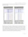
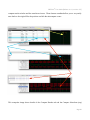
3.4.2.11 Search/Replace
Brings up a query window where search and replace strings may be entered. As with the Search
operation (Section 3.4.2.10) you can elect to perform non case-sensitive as well as regular expression
searches. The screenshot below shows a regular expression being used as a search string, and also
shows the “Count” indicator which displays the total number of strings replaced from the most recent
“Replace All” operation.
Page 41
DFTView® User Guide [Release 10.1.1, revision 173]
3.4.3 Tools Menu
3.4.3.1 Compare Files
Brings up a new Compare Files window where a Compare operation can be configured and run
(Section 5).
3.4.3.2 Merge/Split Bidirs in Display
When a vector file has been opened and the waveform has been displayed, this menu option will
regenerate the waveform with or without bidirectional signals being split into inputs and outputs
(Section 3.6). This effectively allows you to toggle the bidirectional signals in the waveform, but this
is not instantaneous – the vector file will be regenerated.
3.4.4 Help Menu
The Help menu is located on the right-hand side of the menu bar. The first item is About which will
display an application banner which will indicate which version of the DFTView ® you are running.
(Note: If at any time you have a question for Source III please include the version number of the
application, visible in this “About Box”, or simply by typing DFTView –v on the command line).
3.4.4.1 Help Browser
After the “About Box”, the Help menu contains a series of entries each of which will display the
application’s built-in help for that option. So for example, selecting Help → File → Save Source will
display the help text for the File → Save Source menu option. The help browser will remember each
Page 42
DFTView® User Guide [Release 10.1.1, revision 173]
entry as you view it, much like a web browser does, and provides a “Back” and “Forward” button to let
you navigate back and forth, which is useful as you navigate through help files which provide
hyperlinks to additional help entries. Note however that this browsing “history” is not preserved when
you exit the DFTView® application.
3.4.4.2 Contextual Help Browser
As well as the normal online help browser (Section 3.4.4.1) DFTView® also provides a Context
sensitive help feature, which you can activate from the Help → Context-Sensitive Help menu option.
This opens a window, similar to the normal Help browser, but which will only display information
relevant to the operation you are interested in. Move your mouse pointer over any area or control
widget in the DFTView® application. If any specific information is available it will be immediately
displayed.
Page 43
DFTView® User Guide [Release 10.1.1, revision 173]
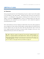
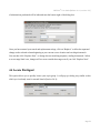
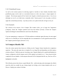
3.5 Error Detection
If DFTView® detects any error while parsing STIL or WGL format input files, it will not attempt to
display any waveform data in the viewer. It will display the input source file in the DFTView ® text
editor as usual and will then jump to the line in the input file which generated the error and highlight.
In the following example, the Procedures statement has been misspelled:
In addition to this, the relevant error message (seen above in the status window) will also be displayed
in a standard dialog box:
Page 44
DFTView® User Guide [Release 10.1.1, revision 173]
After you've dismissed the error box you can get it to display the error again at any time by clicking on
the small “stop” icon next to the highlighted error. At this point you can manually edit the file in
DFTView® and when you're ready click the “Regenerate Display” to re-parse the edited file. This will
cause DFTView® to re-parse the file, and will at this point display the waveforms in the viewer, or
highlight additional error messages if detected.
3.6 Separating Bidirectional Pins
All supported input formats (other than VCD) now support a split bidirectional pin option which
changes how bidirectional pins are displayed in the chosen waveform viewer.
3.6.1 File/Open Dialog
This option is available in the File/Open dialog . When checked (the default state) all bidirectional pins
in the input file are split into input and output pins, clearly labeled, in the resulting waveform display.
This does not in any way alter the content of the input file. This option is only available via the
File/Open dialog (Section 3.4.1). Note that this option is always enabled by default. Uncheck this box
(or pass the --option=noexplicitbidirs command-line option) if you wish to view bidirectional
signals as a single trace in the waveform viewer. You can also click the blue arrow icon just alongside
(Section 3.6.3).
Page 45
DFTView® User Guide [Release 10.1.1, revision 173]
3.6.2 Change via Tools Menu
Once you have displayed your file with dual-trace (split) or single-trace (merged) bidirectional signals,
you can switch between these display formats at will using the Tools → Merge/Split Bidirs in Display
menu option. See Section 3.4.3.2 for more information on this operation.
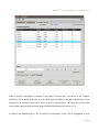
3.6.3 Change via Display Icon
For convenience the current state (merged or split) of the waveform display is indicated by the blue
arrow icon below the main source editor.
Two arrows merging into one indicates merged (single-trace) bidirects.
One arrow splitting into two indicates split (dual-trace) bidirects.
Page 46
DFTView® User Guide [Release 10.1.1, revision 173]
As well as offering this visual indicator, you can at any time click on the icon to switch between
merged and split waveform displays. Each time you click, DFTView® will regenerate the waveform
just as it does when you use the Tools menu (Section 3.6.2). A gray version of the icon indicates that
the option is not currently available, e.g. when viewing VCD or EVCD input formats (Section 3.4.1.1).
3.7 Keyboard Shortcuts
Most operations in DFTView® have keyboard shortcuts mapped to them. The majority of these
shortcuts are displayed on the relevant menu options, and are reproduced in the following table. For
each menu option and button the corresponding keyboard shortcut is displayed, along with a link to the
relevant section in the User Guide, if appropriate.
Operation
Open File
Close File
Regenerate Display
Save Source
Exit
Undo
Redo
Toggle Insert/Overstrike
Previous Vector or Miscompare
Next Vector or Miscompare
Go to Line/Vector
Go to Time Point
Go to Cycle
Search
Search/Replace
Vertical Search
Vertical Search/Replace
Locate Pin/Signal
Smash
Compress
Go to Previous Change
Go to Next Change
Shortcut
Control O
Control W
Control R
Control S
Control Q
Control Z
Shift Control Z
Insert
Control < (or Control ,)
Control > (or Control .)
Control L
Control T
Control Y
Control F
Control G
Control /
Control |
Control P
Control +
Control Control [ (left square bracket)
Control ] (right square bracket)
Section
3.4.1.1
3.4.1.2
3.4.1.3
3.4.1.5
3.4.2.8
3.2.4
3.2.4
3.4.2.4
3.3.3
3.3.4
3.4.2.7
3.4.2.8
3.4.2.9
3.4.2.10
3.4.2.11
4.2
4.3
4.4
4.5
4.5
4.6
4.6
Page 47
DFTView® User Guide [Release 10.1.1, revision 173]
Compare Files
Control K
5
3.8 Disabling Waveform or Source Editor Function
In typical use, source files opened in DFTView® are displayed in a source editor and an associated
waveform is displayed in the pre-configured view application (Section 1.4.3). In some circumstances it
may be preferable to change this behavior, viewing just one or the other.
3.8.1 Disabling Waveform
For all supported input formats, you can elect to disable or defer waveform generation and display.
You can either use the -nowfm or --option=no_waveform arguments when specifying the source file
name(s) on the command-line (Section 2.1.1), or deselect the “Generate and Display Waveform”
display option in the File/Open dialog (Section 3.4.1.1). The source file will be opened and displayed
in the editor as usual, but the waveform application will not be launched, and the source ↔ waveform
interaction controls such as “Previous Vector”, “Next Vector” etc. will be disabled since there is no
waveform to interact with (Section 3.3).
This mode of operation cuts down on file load times, since the task of generating the vectors for display
along with the source/waveform mapping to keep everything synchronized does not need to be
executed. In addition, file formats such as T2000, 93K/HPTAB which require timing files for display
can be loaded without them. Source-only features like search, and all the V-mode operations (Section
4) including V-mode file formatting, are fully accessible when no waveform is displayed.
At any time, even after editing/changing a source file displayed in this fashion, you can elect to click
the 'Generate Display' button (or select the similarly-named menu option) and the waveform will be
computed and displayed. If timing files are needed at this stage, you will be prompted for them
automatically.
Page 48
DFTView® User Guide [Release 10.1.1, revision 173]
3.8.2 Disabling Source Editing
For VCD and EVCD files, you may instead opt to load and view the waveform without loading the
source file at all. Use the -nosrc or option=no_source command-line options, or deselect the
“Display Input File in Source Editor” display option in the File/Open dialog.
This mode of operation can reduce load times, especially for large files since the mapping functions to
keep the source and waveform in sync do not need to be executed. Again because the mapping
operation is deferred, the interaction controls will not be available, but the source file can be loaded
later by means of the “Load Source Files” button or menu option. This will open the source file in the
DFTView® editor, and also generate the vector mapping needed for normal source ↔ waveform
interactions.
Note: In the case of VCD and EVCD files, where both these options are selectable, note that you must
select at least one or the other, or select both. You cannot proceed if you deselect both options (since
you're telling DFTView® to not do anything!).
Tip: When comparing files (Section 5) both files must be opened with source (VCD/EVCD)
and waveform (all formats). When you attempt to compare files without source or waveform
being displayed, you will be prompted to correct this before you can continue. See also
“Entering Compare Mode“, Section 5.2.
Page 49
DFTView® User Guide [Release 10.1.1, revision 173]
4 DFTVIEW V-MODE
®
4.1 Overview
When opening 93k format files in the File/Open dialog, the option to enable V-mode will be available
(it will be disabled for other input formats).
Selecting this option will alter how the input file is
presented to you (although the various controls for interacting with the waveform viewer will not
change). As described in “Running DFTView®” (Section 2), if passing the names of the input vector
and timing files on the command line you can also specify the –vmode command line argument to
switch automatically into V-mode.
With V-mode enabled, pin state data is displayed in tabular fashion where each column represents the
state of a single pin over time, and above the main display a secondary display will vertically label each
pin name, aligned over the correct pin state column. Unlike the normal edit mode, lines in V-mode will
not be wrapped automatically, and instead a horizontal scrollbar will appear to allow you to view
additional pins if they do not all fit in the window at once.
Tip: When a 93K file is opened in V-mode the Cycle and Vector numbering begins at 0
instead of 1, to match the behavior of the Advantest testers. However, the Cycle number still
begins at 1 for 93K files displayed in normal mode, just as it does for any other format. This
is especially important to remember if you synchronize two tabs (Section 3.2.2) where only
one is in V-mode, as it may appear that the cycle numbers are off by one.
Page 50
DFTView® User Guide [Release 10.1.1, revision 173]
When displayed in V-mode the file will be represented as a series of vectors and possibly loops (you
can identify these by the SQPG statement delimiters). Other statements such as SCAN are not
displayed, and if your input vector file contains SCAN statements these will be automatically flattened
into a series of vectors before being displayed. If you alter and save the file note that it will not convert
these flattened vectors back into SCAN statements.
Just below the text editor pane in DFTView ® and above the row of command buttons (Section 3.3),
additional information will be displayed about the cursor position in an open vector file. The first line
will show the vector and cycle number of the currently-selected line, and if the cursor falls on a pin
column the name of that pin will also be displayed. Also when the cursor falls on a pin column, a
second line of data (labeled “Signal Data”) will show a horizontal representation of the pin state data
Page 51
DFTView® User Guide [Release 10.1.1, revision 173]
beginning at the cursor location and reading downwards as shown here.
The pin state value under the cursor will always appear in the white box next to the “Signal Data” label,
and the number of characters of pin state data displayed along the row will expand as the window is
expanded. However, if you select a line near the end of the file you may see less than a full windowwidth of pin state data. Pin state data represents what you can see in the currently-selected pin column.
If you “smash” or “compress” a vector (Section 4.3), the pin state data will be updated to match. If
you quickly want to switch between normal and fully smashed pin state data you can toggle the “Smash
Preview” check button near the bottom right of the application window, and the pin state data in the
row will be updated immediately.
V-mode is an enhanced version of Normal mode, in that all normal mode operations (Search,
synchronizing vector line position with waveform cursor position etc.) are still in effect (Section 3).
The Edit → Go to Line Number is replaced with two similar operations “Go to Vector” and “Go to
Cycle”.
In addition extra operations are available via a new specific V-Mode menu which appears
alongside the normal Edit menu:
-
V-Mode (drop-down menu)
V-Mode → Vertical Search
V-Mode → Vertical Search/Replace
V-Mode → Locate Pin/Signal
V-Mode → Smash
Page 52
DFTView® User Guide [Release 10.1.1, revision 173]
V-Mode → Compress
V-Mode → Smash All Repeats
V-Mode → Compress All Repeats
V-Mode → Load V-mode Format File
V-Mode → Remove V-mode Formatting
V-Mode → Go to Previous Change
V-Mode → Go to Next Change
4.2 Vertical Search
Along with the regular Search option (Section 3.4.2) V-mode also provides additional search behavior
for the application. In normal mode, search is performed in a standard “text-editor” fashion, scanning
line by line until a match is found. As seen in the extra Edit menu options above, both “Vertical
Search” and “Vertical Search & Replace” options are available. The Vertical Search operation allows
the user to search vertically on any selected column representing a single pin, although you can elect to
search all columns (pins) as well. If all pins are being searched each pin will be highlighted in turn as
its pin state data is searched for a matching pattern, and because this can be a time-consuming
operation it can be interrupted at any time with the “Stop Search” button.
4.3 Vertical Search/Replace
In V-mode you can search for and replace a sequence of state characters on a single pin. With a pin
selected you can call up this dialog box and use it to substitute new state sequences on the selected pin.
Use the “Limit to vector range” entries if you wish to limit the “Replace All” operation to within the
range you specify – if you do not specify a limit the replacement operation will be carried out on all
vectors for the pin you selected. As shown here, when you use the “Replace All” button, the number
Page 53
DFTView® User Guide [Release 10.1.1, revision 173]
of substitutions performed will be indicated near the bottom right of the dialog box.
Once you have entered your search and replacement strings, click on “Replace” to affect the requested
change on the selected column beginning at your current cursor location and working downwards.
You can then click “Replace Next” to change the next matching sequence, reading downwards. When
a vector range limit is set, changes will not occur outside that range even if you click “Replace Next”.
4.4 Locate Pin/Signal
This option allows you to quickly locate a pin or pin group. It will pop up a dialog very similar to that
which you’ve already seen for normal Search (Section 3.4.2):
Page 54
DFTView® User Guide [Release 10.1.1, revision 173]
4.5 Smash and Compress
The Edit menu also provides additional options when a file has been opened in V-mode. If the cursor
is sitting on a vector line which has a repeat value > 1, or is inside a loop block (wrapped in SQPG
RPTV and SQPG PADDING statements) the “Smash” will be enabled and the arrow cursor to the left
of the text pane will change to bright green. Such vectors and loops can be “smashed” (also known as
“expanded” or “flattened”) such that each repeated vector is explicitly listed in the source window
(similarly for loops where each set of vectors will be explicitly listed). For convenience, a smashed
repeat vector or loop will be highlighted in light blue so they can be easily and quickly identified. The
companion “Smash all Repeats” will iteratively smash any vector or loops with a repeat count greater
than one. Note that for large files this process may take some time to complete. Complementing these
“Smash” options the Edit menu also provides both a “Compress” and “Compress all Repeats” option.
The “Compress” operation will only be enabled when the cursor is sitting on a previously smashed
block or loop. As with the “Smash” option, if the arrow cursor is aligned with such a previously
smashed entry it will again change color to green indicating the “Compress” operation is available.
The text-editor cursor may be placed anywhere in the smashed block, and selecting this option will
replace the block with the original single vector line or loop block Just as you'd expect, the “Compress
all Repeats” option will compress all vectors or loops which have been previously smashed. The
following screen shot shows a smashed repeat vector:
Page 55
DFTView® User Guide [Release 10.1.1, revision 173]
Tip: When using the “Smash” and “Compress” operations it is possible for the cycle/vector
correlation to go out of sync. If the cycle and vector numbers (Section 4.1) both show zeros
or otherwise seem to be incorrect, and especially if the “Regenerate Display” button is
flashing, don’t forget to click the “Regenerate Display” button to refresh the waveform
display and vector numbers (section 3.3.1).
4.6 Other Operations
Two other useful operations are available in V-mode. The last two Edit menu options, “Go to Previous
Change” and “Go to Next Change” provide a convenient way to jump the previous or next pin state
Page 56
DFTView® User Guide [Release 10.1.1, revision 173]
change on a given pin column, without necessarily knowing what the particular changed state will be.
This option will also only be enabled if the cursor is sitting on a pin state column.
4.7 Pin Selection and Formatting
While displaying all the signals and their corresponding waveforms from the input file is already
extremely useful, V-mode adds another feature to facilitate narrowing down the amount of information
you wish to examine – V-mode Formatting.
This is accomplished by way of a pin formatting file which can be loaded into DFTView ® via the VMode → Load V-mode format file menu option, and used to define which signals should be viewed,
and in which order.
To undo the operation, select Remove V-mode formatting from the V-Mode
menu.
Tip: If pin formatting is applied (i.e. you have already loaded a V-mode format file), you can
re-apply this format file after editing it in an external editor, or apply a different format file,
by using the same menu option which will now read “Load/Reload V-mode Format File”.
This will automatically remove the current pin formatting (preserving any changes to the
vector file you may have made) and apply the updated pin formatting file in its place.
4.7.1 Basic File Format
The pin formatting file is itself a very simple INI-style text file. It must at the very least contain a
[display]
section which tells DFTView® which signals to display, e.g.:
[display]
INPUT[3]
INPUT[2]
INPUT[1]
INPUT[0]
SPACER
CLK_A
CLK_B
In this example, four input pins constituting a bus should be displayed, followed by a blank column and
Page 57
DFTView® User Guide [Release 10.1.1, revision 173]
then two clock signals. The SPACER statement can be used as many times as you wish to further
separate out signals you wish to view (note all caps are required for this keyword - the lower-case
string “spacer” or any mixed-case variant thereof will be interpreted as a signal name). These spaces
will appear as blank columns in the vector display (text editor), but there will be no corresponding
spaces in the waveform display. The signals themselves will be displayed in the same order as listed in
both in the text editor and the waveform viewer. You may put comments in the format file by
beginning the line with a # character, and blank lines and spaces are allowed. Section titles such as
[display]
are not case-sensitive, but note that pin/signal names are.
You do not need to list every signal in your vector file. For example this can be a very convenient way
of displaying only those signals you're interested in, without needing to convert or edit your input file
in any way.
You can also list the same signal two or more times for display, but see Section 4.7.5 for some
limitations on this feature.
4.7.2 Named Pin Groups
You can also optionally define a pin group via a [pingroup] section. The first line in such a section
should be the name of the pin group, and subsequent lines should list the signals making up this pin
group, in the order you wish to add them. The name of a pin group must not be the same as the name
of an individual signal or the pin group will be ignored. The signals can be listed on one line or split
across multiple lines and note that spaces are not allowed on any of the lines shown below. The
following two pin group declarations are equivalent:
[pingroup]
name=INPUT[3:0]
signals=INPUT[3],INPUT[2],INPUT[1],INPUT[0]
[pingroup]
name=INPUT[3:0]
signals=INPUT[3],INPUT[2]
Page 58
DFTView® User Guide [Release 10.1.1, revision 173]
signals=INPUT[1]
signals=INPUT[0]
The name of the pin group can then be listed in the [display] section and that complete group will be
displayed.
You may list the same signal in multiple pin groups and display them, but as with single signals, there
are some limitations on displaying them (Sections 4.7.5 and 4.8).
As with single signals, not all pin groups must be displayed – you can declare all of your pin groups as
shown here, but then only list a few of them in the [display] section.
4.7.3 Single-bit Buses As Pin Groups
When specifying the name of a pin group, you may specify single-bit buses in single-index or dualindex forms. The following two entries are equivalent:
name=SIGBUS[0]
name=SIGBUS[0:0]
This form of a single-bit bus can be used interchangeably in the name= section of a [pingroup] and in
the [display] section. You can define a pin group with a name of SIGBUS[1:1] and then reference it
in the [display] section using the name SIGBUS[0], or vice-versa. Note however that you cannot use
this form in the signals= section of a pin group (Section 4.7.2) because this section must list every
signal separately.
4.7.4 Display Radix
Pin groups can be displayed in binary or hexadecimal. The side-by-side screen shot sample on the
following page demonstrates a file displayed in DFTView ® with V-mode, before and after pin
Page 59
DFTView® User Guide [Release 10.1.1, revision 173]
formatting has been applied. Notice how the hexadecimal display makes it easier to read the state of
the selected bus (column).
By default a pin group will be displayed in binary form, and if no formatting option is listed after a
signal or pin group in the [display] section, the BIN formatting option (case-insensitive) is assumed.
When a pin group is displayed in BIN format the Vector/Cycle/Pin information near the bottom of the
window will indicate both pingroup and component pin name at the cursor position where applicable.
When displayed in HEX (see next paragraph), all four component pin names which make up the single
column at the cursor position will be listed in parentheses after the pingroup name.
Page 60
DFTView® User Guide [Release 10.1.1, revision 173]
You may also specify HEX in which case each four pins will be translated in order into the relevant
hexadecimal character if possible.
[display]
SPACER
CLK
INPUT[3:0]
hex
For example, if at a given vector our input file for pins INPUT[3], INPUT[2], INPUT[1] and INPUT[0]
listed the states as 0,1,0,0, then in hex that would be displayed as 4. Likewise for low/high pin states,
in this case LHLL. If the four states cannot be combined into a hex character, a ‘?’ character will be
displayed instead. So four pin states 01XX or X00X would both be displayed as ? (but will correctly
revert to their original states once pin formatting is removed). The only exception is where all four
characters are the same 'X' state: here XXXX would be displayed as X. Hexadecimal values may be
edited and the change will be retained when pin formatting is removed. Thus changing a 0 to an F
which displayed in hex will change the original pin states from 0000 to 1111 or LLLL to HHHH as
applicable.
Pin states are interpreted in the order they are listed. To display a bus of four pins in most-significantbit (MSB) order listed them low to high (e.g. SIG[0:3]) while for LSB ordering they should be listed
high to low (e.g. SIG[3:0]). In the previous example, the INPUT bus is interpreted in LSB order.
Here's one way to display the same bus in both LSB and MSB forms:
[pingroup]
name=BUS[7:0]
signals=SIG[7],SIG[6],SIG[5],SIG[4]
signals=SIG[3],SIG[2],SIG[1],SIG[0]
[pingroup]
name=BUS[0:7]
signals=SIG[0],SIG[1],SIG[2],SIG[3]
Page 61
DFTView® User Guide [Release 10.1.1, revision 173]
signals=SIG[4],SIG[5],SIG[6],SIG[7]
[display]
BUS[7:0]
hex
SPACER
BUS[0:7]
hex
4.7.5 Declaring Duplicate Pins
You may list any signal multiple times in the [display] section (Section 4.7.1), and it will be repeated
as columns within the V-mode source editor in the order it was listed. These repeated signals do not
need to be adjacent – they can be listed in any order, as shown in this example, where a clock signal is
placed alongside two different buses of interest:
[display]
SPACER
CLK_A
LARGE_BUS[127:0]
CONTROLPIN
CLK_A
INPUT[3:0]
If your configured waveform display application is Synopsys nWave/Verdi (Section 1.4.3) you will see
a duplicate trace for each duplicate pin. However, if you are using GTKWave you will see a trace only
for the first occurrence of that signal. This applies whether the signal is listed standalone or included as
part of a pin group.
Even if using Synopsys nWave/Verdi you are further limited to seeing a single bus or set of traces if
you list the same pingroup multiple times in the [display] section (they will, as always, be correctly
displayed in your source editor). Since you can display the same pin in different pin groups however,
you can simply define a second pingroup with the same makeup as the first, and that will display as a
separate bus or set of traces, as shown here:
Page 62
DFTView® User Guide [Release 10.1.1, revision 173]
[pingroup]
name=DUPLICATE_A[3:0]
signals=SIG[3],SIG[2],SIG[1],SIG[0]
[pingroup]
name=DUPLICATE_B[3:0]
signals=SIG[3],SIG[2],SIG[1],SIG[0]
[display]
SPACER
DUPLICATE_A[3:0]
DUPLICATE_B[3:0]
There is one more important restriction you should be aware of. When displaying multiple pin groups
no pin group which shares a pin with another can be displayed with a hexadecimal radix (Section
4.7.4). You must use a binary radix in the [display] section (or no radix, which defaults to binary).
4.8 Editing Columns When Formatted
When pin formatting is applied, you can make changes in the main source editor to the state of any
displayed pin at any time point, and these changes will be retained if the pin formatting is subsequently
removed (via the V-Mode → Remove V-mode Formatting menu option).
It is important to note that if a pin is displayed multiple times (as in the previous example), only
changes to the first occurrence of that pin will be preserved. So in this case if you wish to edit CLK_A
in the main source editor (Section 3.2) you must do so to the left-most CLK_A column – edits to any
following column representing the same pin will be lost.
Similarly, while you will see separate traces for each duplicated pin entry if using Synopsys
nWave/Verdi, these traces are linked to the left-most column in the source editor. Any edits made to
that column will be reflected in every duplicate waveform trace when you perform a “Regenerate
Page 63
DFTView® User Guide [Release 10.1.1, revision 173]
Display” operation (Section 3.3.1), while edits to second or subsequent duplicate columns will have no
effect.
Tip: Editing the state of duplicate signal which is part of a bus further complicates the issue
- since buses are typically displayed in the waveform viewer showing their hexadecimal
value, the values of EVERY bus which shares that pin will change when you “Regenerate
Display”. If you are editing duplicate pins and things start to look out of sync, Reapply Vmode Formatting (Section 4.7) to help clear things up.
Page 64
DFTView® User Guide [Release 10.1.1, revision 173]
5 DFTVIEW COMPARE MODE
®
5.1 Overview
DFTView® provides a consistent way to view the waveforms from different file formats.
With
DFTView® Compare Mode you can open two files representing the same vector set (e.g. an EVCD and
a VTRAN®-translated STIL file), view the associated waveforms, and compare the vectors.
This is not a byte-by-byte diff of two text files, but instead a comparison of state and/or transition
differences. The results are displayed as an ordered (by time) collection of miscompares (points where
the vectors differ) along with a customized waveform representation of them. Each miscompare will
be displayed as a peak on an otherwise linear waveform trace (where each signal is represented by a
trace).
Unlike a normal source editor/browser window, the results of a Compare are displayed in a custom tab
which displays compare parameters, total miscompare count, along with a table which describes the
details of each miscompare (e.g. at which time, and on which signal the miscompare occurs). A
modified set of controls allows you to navigate through each miscompare in much the same way as you
navigate through a source file; you can use the Next/Previous Miscompare buttons to skip from one
miscompare to the next, or by clicking on or near a specific miscompare on the waveform display and
synchronizing the Compare Results tab to the nearest miscompare.
Below the table are a series of filters where you can restrict the display to a certain beginning and/or
end time, string search on signal names, and select specific subsets of direction, type (hard or soft), and
reference and source state characters.
Page 65
DFTView® User Guide [Release 10.1.1, revision 173]
Page 66
DFTView® User Guide [Release 10.1.1, revision 173]
5.2 Entering Compare Mode
There are two different methods to enter Compare Mode, and in both cases a 'Compare Files' window
will be displayed where you can enter/change compare parameters.
In the first method, simply open your two vector files and/or test pattern files as you would normally
do (Section 3.4.1.1). As soon as both files have been opened, and the waveforms are displayed, the
Tools → Compare Files menu option will become enabled. Select this option, or use the “Control-K”
keyboard shortcut, and the 'Compare Files' window will be opened.
As a second method, you can also enter Compare Mode by passing the --compare command-line
option to DFTView®:
DFTView file1.stil file2.vcd --compare
Note that you must also pass in two files for DFTView® to open and display or the command will be
rejected and DFTView® will not run. The order of the --compare option is unimportant (it can be
place before, after, or even between the two filenames).
Tip: When comparing an EVCD file to a different format, or two EVCD files against each
other, DFTView® must first normalize them by setting signal strengths to 6 or 0 on all
transitions, and limiting the number of available states. This process may be time-consuming
for large files, and DFTView® will prompt you for confirmation before doing so.
Page 67
DFTView® User Guide [Release 10.1.1, revision 173]
5.3 Compare Files Window
This window controls all aspects of the Compare operation, from selecting which files to compare (you
select from among the available open tabs), which compare mode to use, what time range to examine,
which signal states to ignore, and so on.
Page 68
DFTView® User Guide [Release 10.1.1, revision 173]
5.3.1 File Selection
DFTView® Compare Mode operates on the waveforms which have already been opened and displayed.
When the Compare Files window opens, you can select which tab to use for the reference waveform,
and which to use as the source waveform.
Tip: When launching DFTView® Compare Mode via the command-line, the first named file
will be preassigned as the Reference and the second will be preassigned as the Source. If
you want to change this arrangement just click the 'Reset' button and re-assign them.
Selecting the Reference and Source files is required, but all other settings on this window are optional
and the defaults can be accepted. At this point you can click the 'Compare' button and DFTView ® will
perform the vector comparison and then report the results of the comparison (Section 5.4).
When an EVCD file is used in a Compare operation, a VCD file must first be generated. You will see
this notice when attempting to perform a Compare where at least one file is in EVCD format:
You can choose to cancel the operation at this point (in which case no Compare will be performed). If
you elect to proceed, the Compare will begin automatically as soon as the VCD intermediate has been
generated. (EVCD files loaded with the preprocess option (Section 3.6.1) already have a VCD
intermediate and will not require this normalization step).
Note also that when a VCD file is generated in this situation, bidirectional signals will always be split.
Page 69
DFTView® User Guide [Release 10.1.1, revision 173]
This retains the signal direction information from the EVCD states at each event.
5.3.2 Compare Options
There are quite a few options which can be used to control how the comparison will be performed.
While the default options are very useful, and have been selected to provide what we believe is a very
useful starting point when performing a comparison, by changing these options you can easily zero in
on a section of interest.
5.3.2.1 Compare Mode
There are four different compare modes available:
a) Trans-State
For every selected pin state transition in the Reference File, the new pin state is verified against
the pin state from the Source File at the same time point.
•
The comparison is triggered by a pin state transition in the Reference file on a given
signal.
•
The new pin state in the Reference file is compared against the new pin state at the
corresponding time point in the Source file.
Page 70
DFTView® User Guide [Release 10.1.1, revision 173]
•
A miscompare is reported when the new pin states do not match and the Ignore State
directives do not apply.
•
A miscompare is reported as a "SOFT" miscompare when the new pin state is either X
or Z in either the Reference or the Source file and the Ignore State directives do not
apply.
b) Trans-Trans
For every selected pin state transition in the Reference File, the Source File is checked to see
that the same pin made an identical transition at the same time.
•
The comparison is triggered by a pin state transition in the Reference file on a given
signal.
•
Both the previous and the new pin states in Reference file are compared against the
previous and new pin states at the corresponding time point in the Source file.
•
A miscompare is reported in two cases. The first case is when either the previous pin
states or the new pin states do not match and the Ignore State directives do not apply.
The second is when there is no transition in the Source file.
•
A miscompare is reported as a "SOFT" miscompare when either the previous or the new
pin state is X or Z (in either the Reference or the Source file) and the Ignore State
directives do not apply. A miscompare caused by no transition in the Source file is
always a "HARD" miscompare.
c) State-State
For every time stamp in the Reference File with a transition on any pin, the states of all selected
Page 71
DFTView® User Guide [Release 10.1.1, revision 173]
pins in the Reference File are compared with pin states of the Source File at the same time
point.
d)
•
The comparison is triggered by each time stamp in the Reference file where at least one
signal has a transition.
•
The pin state in the Reference file is compared against the pin state at the corresponding
time point in the Source file.
•
A miscompare is reported when the pin states do not match and the Ignore State
directives do not apply.
•
A miscompare is reported as a "SOFT" miscompare when the pin state is either X or Z
in either the Reference or the Source file and the Ignore State directives do not apply.
e) Bidirectional
(default mode)
For every time/state data point in either the Reference or the Source files, the other file is
checked for an identical time/state data point. This essentially amounts to doing an exclusiveOR of the time/state information in the two files.
•
The comparison is triggered by a pin state transition in either the Reference file or the
Source file on a given signal.
•
The new pin state in the Reference file is compared against the new pin state at the
corresponding time point in the Source file.
•
By default, a miscompare is reported only when the signal is compared, the new pin
states do not match and the Ignore State directives do not apply.
Page 72
DFTView® User Guide [Release 10.1.1, revision 173]
•
Using the "Report_Recurring_Mismatches" option, a miscompare on a given signal is
also reported in the Report File whenever there is a pin state transition in either the
Reference file or the Source file on any other signal.
•
A miscompare is reported as a "SOFT" miscompare when the new pin state is either X
or Z in either the Reference or the Source file and the Ignore State directives do not
apply.
5.3.2.2 Check Signals
This lists (one per line) the signals which are to be included in the comparison.
By default this panel will list every detected signal, and the button to the top right will indicate “All
Signals”. You can click this button to open the Signal Browser where you can edit which signals are to
be included, either by selecting them manually or by choosing one of the preset groups such as “Input
Signals Only” or “Output Signals Only”. The Signal Browser is explained in detail in Section 5.3.3.
5.3.2.3 Compare Window
This is applicable only to output and bidir-out signals, and specifies a relative start and stop time
outside which all comparisons should be masked – a comparison is skipped if the event time relative to
the start of the current cycle is outside the window. The start and stop times are applied to all output
and bidir-out signals.
Page 73
DFTView® User Guide [Release 10.1.1, revision 173]
The use of a Compare Window is applicable only when the Reference File and the Source File both are
(E)VCD, the direction of signals has been specified by the user (in the case of VCD), and at least one
(E)VCD file has separate tracks for bidirectional signals.
5.3.2.4 Compare Range
The Compare Range, specified either in time units or vector numbers, provides an absolute range in
which the comparison will be applied. No comparison will be performed either before the lower limit
or after the upper limit. By default there are no limits (Start Compares at 0, and End Compares at '*'
which signifies the end of the Reference File.
5.3.2.5 Ignore Miscompares When
Miscompares fall into two categories - “Hard” and “Soft”, the meaning of which depends on which
Compare Mode (Section 5.3.2.1) is set (see below). Which ever Compare Mode is set however, “Soft”
miscompares always involve one or the other states (or before/after states in the case of Trans-Trans)
being an X or a Z. Any mismatch between a 1 and a 0 is always considered a “Hard” mismatch, and
none of these checkboxes will change how they are displayed.
a) Trans-State
If the new Reference File state and/or the Source File state is X or Z, and the corresponding
Ignore Miscompare State is not specified, and the states do not match, this is reported as a "soft
mismatch" in the Comparison Result.
If the new Reference File state and/or the Source File state is X or Z, and the corresponding
Ignore Miscompare State is specified, and the states do not match, this is treated as a match.
b) Trans-Trans
Page 74
DFTView® User Guide [Release 10.1.1, revision 173]
If the previous Reference File state and/or the previous Source File state is X or Z, and the
corresponding Ignore Miscompare State is not specified, and the states do not match, this is
reported as a "soft mismatch" in the Comparison Result.
If the previous Reference File state and/or the previous Source File state is X or Z, and the
corresponding Ignore Miscompare State is specified, and the states do not match, this is treated
as a match.
If the new Reference File state and/or the new Source File state is X or Z, and the
corresponding Ignore Miscompare State is not specified, and the states do not match, this is
reported as a "soft mismatch" in the Comparison Results tab. If the new Reference File state
and/or the new Source File state is X or Z, and the corresponding Ignore Miscompare State is
specified, and the states do not match, this is treated as a match.
c) State-State
If the Reference File state and/or the Source File state is X or Z, and the corresponding Ignore
Miscompare State is not specified, and the states do not match, this is reported as a "soft
mismatch" in the Comparison Report.
If the Reference File state and/or the Source File state is X or Z, and the corresponding Ignore
Miscompare State is specified, and the states do not match, this is treated as a match.
d) Bidirectional
If the Reference File state and/or the Source File state is X or Z, and the corresponding Ignore
Miscompare State is not specified, and the states do not match, this is reported as a "soft
mismatch" in the Comparison Results tab.
If the Reference File state and/or the Source File state is X or Z, and the corresponding Ignore
Miscompare State is specified, and the states do not match, this is treated as a match.
Page 75
DFTView® User Guide [Release 10.1.1, revision 173]
When comparing a VCD with an ATE file (for example the result of a VTRAN ® translation) you may
see more soft miscompares than you might expect – specifically where an X occurs in place of a Z or a
Z in place of an X. This may also be observed when comparing two files where one has split
bidirectional signals and one does not (for example if you have checked the "Split Bidirectional Pins"
option (Section 3.4.1.1) when opening one file, but not when opening the other). In this particular case,
the compare operation checks the signal's bidir-in state in the file where split bidirs has been enabled.
If the state is Z, it uses the bidir-out state for the comparison, otherwise, it uses the bidir-in state for the
comparison. The selected state is compared to the single state in the file with combined bidirs. This rule
is applied both to previous states and new states.
The “For Bidir Signals” checkboxes are not applied when comparing an EVCD file, since all
bidirectional signals are split into input and output traces (Section 5.3.1).
The default Ignore options which DFTView® applies (i.e. which Ignore checkboxes are enabled
automatically) have been chosen to best reflect cases where an X occurring instead of a Z is to be
expected. However if you are seeing a lot of soft miscompares, you can choose to enable more of the
Ignore options that are available (12 in all) to narrow down these miscompares to only those which are
of interest.
You can use the tags labeled [check all] and [uncheck all] in this to quickly select or deselect all the
ignore miscompare options at once. NOTE: We recommend caution when using [check all] since you
are telling DFTView® to ignore all “Soft” errors, and this may cause you to miss an important
transition or state difference.
5.3.2.6 Compare Results Format
Unless your DFTVIEW_DISPLAY environment variable has been set to None (Section 1.4.3), the
default is that any miscompare results will be shown both in report form (in the form of a Compare
Results tab (Section 5.4) and a custom waveform view, where Hard errors are shown as 1 in red, and
Soft miscompares are shown as X in yellow. This graphical representation of the waveforms makes it
easy to visually inspect the resulting “waveforms” for clusters of miscompares or other areas of
Page 76
DFTView® User Guide [Release 10.1.1, revision 173]
interest. You can instead elect to show the miscompares in Report form (Results tab) only, and if your
DFTVIEW_DISPLAY environment variable is None, this will be the only option available.
If no
miscompares are reported, no waveform display will open regardless of your DFTVIEW_DISPLAY
and Compare Results Format settings.
Tip: If you have configured Synopsys nWave or Verdi for your waveform viewer, these colors
will be slightly different – green for 1 (hard miscompare) and red for X (soft miscompare).
In addition, if you are using a custom novas.rc file your defined Verilog Digital colors for 0,
1 and X states will take preference (in nWave you will find these settings under Preferences
→ Waveform → Value System → verilog_digital).
5.3.3 Signal Browser
The Signal Browser lists available signals for comparison. It presents two lists of signals – the one on
the left lists all available signals, while the one on the right lists which signals are to be considered
when performing the comparison. By default, the latter contains all available signals.
For most file formats which DFTView® supports (Section 1.3) the signal directions are known, and
Page 77
DFTView® User Guide [Release 10.1.1, revision 173]
listed alongside the full signal list (left pane). However, when comparing straight VCD to VCD files,
these directions are unknown and in this case you can use the built-in Direction Editor (Section 5.3.3.3)
to define signal directions.
5.3.3.1 Signal List
This provides a list of all available signals, read automatically from either Reference or Source file.
This list is preferentially read from an ATE file (e.g. STIL, WGL, SVF etc.) if one of the two files to be
compared is in such a format since all directional information is included. If neither file is ATE file the
list of signals will be read by the Reference VCD file (unless one of the pair of files is an EVCD file in
which case that will be used).
By using this order of preference DFTView ® ensures it will have all
signal directional information wherever possible.
5.3.3.2 Filter (regex)
This input box allows real-time filtering of the Signal List (Section 5.3.3.1) just above it. As you type
in this box the list of signals will be limited to those which include the text you enter. Why should this
be useful? You could for example filter the full list of signals to only include those with an 'a' in their
name, and then right click this list to “Select All” and then right-click again to “Add to Signal List” to
quickly include these in the list of signals to be included in the comparison. These signals would then
be added to the 'Signals to Include' pane on the right (Section 5.3.3.4).
In the simplest form, just type a few letters of the signals you're interested in and the list will be
updated to only include those signals. If you want more refined filtering you can also use regular
expressions (regexes). For example, to include signal names which begin with the letter 'S' followed by
'I' you would enter:
^si
This would include signal names such as “signal2” and “SigOut” but exclude other names such as
“AllSignals” (the 'S' in this case is not at the beginning of the name).
Note that any filter you use,
whether a regex or not, matches on a case-insensitive basis. Consult an online guide to regular
Page 78
DFTView® User Guide [Release 10.1.1, revision 173]
expressions for more detail on this extremely powerful form of pattern matching.
To undo filtering so that all signals are displayed again just erase all characters in this box.
5.3.3.3 Direction Editor
As noted previously, in most cases signal direction information is automatically extracted from any
ATE or EVCD file which is included in the comparison. In the case of VCD to VCD files however, the
onus is on the user to provide this information. You can right click on a signal or highlight a group of
signals and then right-click on the group. In either case you can then define the signal direction to one
of input, output, bidir, and for split bidirectional signals, bidir-in or bidir-out. This added direction
information is required when performing a bidirectional comparison (Section 5.3.4). If you don't know
this directional information, you can use the “Suggest a direction” option from the contextual menu
(displayed when you right-click). This is only a best guess and is not guaranteed – use this as a last
resort only.
DFTView® will display a warning if any signal directions are listed as 'unknown' when you invoke the
'Compare' button. At this stage you can click “Cancel” to (re-)open the Direction Editor, or “Ok” to
proceed – in this case DFTView® will make a best guess for all signals without assigned directions and
continue. However, again please note that it is recommended you assign signal directions if possible
beforehand.
5.3.3.4 Signals to Include
Much like the Signal List in the left pane (Section 5.3.3.1) this lists signal names, however in this case
the list explicitly names which signals should be included in the comparison. Signals not listed in this
pane will be ignored in the comparison. By default all signals are listed, but as with the Signal List you
can right-click one signal or a group of signals, this time to remove them from the list. Unlike the
Signal List which cannot be changed (other than filtered – see Section 5.3.3.2) you can also manually
type signal names into this pane, as well as pasting them in from an external place where you've copied
them – perhaps a separate signal list file.
Page 79
DFTView® User Guide [Release 10.1.1, revision 173]
5.3.3.5 Predefined Groups
As well as the various options for selecting signals to include we have already described, these
predefined groups can be used as a convenient shortcut to select only input or output signals, for
example. The relevant signals will be listed in the 'Signals to Include' pane just above. You do not
(although you can if you wish) have to manually select 'Custom group' if you are going to edit the
signal list as described previously – any time you edit, cut or paste the list this will get set for you.
5.3.4 Controls
The controls at the bottom of the Compare Files window allow you to begin the Comparison
(Compare), Cancel the Compare operation and close the window (Cancel) or Reset the Compare
Options including the selected Reference and Source files (Reset).
If you are attempting to compare two VCD files and have not defined signal directions for each signal
which is to be included you will be reminded that it's recommended to set all signal directions before
the Compare operation begins (Section 5.3.3.3).
5.4 Compare Results Tab
Once the various options have been set, clicking on the 'Compare' button launches the comparison
operation. This may take some time to complete for very large files and depending on which options
you have selected. While the process is running a new Compare Results tab is opened and displays the
current configuration (which compare mode, which signals are included, etc.). Once the process has
completed, the total number of miscompares detected will be displayed and the very first one will be
highlighted in the table.
The following screen shot shows a typical Results Tab: a table showing each miscompare (by default
sorted by time, but sortable by any column simply by clicking on the column headers) and a set of
filters to display just a subset of the data.
Page 80
DFTView® User Guide [Release 10.1.1, revision 173]
When a specific miscompare is selected in the table, as shown here, the cursor in the Compare
Waveform will be placed at the time point at which the miscompare occurs, and in addition the cursor
positions of the Reference and Source tabs will also be repositioned to the same spot in both their
source editors and waveform windows using Synchronized Navigation (Section 3.2.2).
In addition the named signal or bus at which the miscompare occurs will be highlighted in both
Page 81
DFTView® User Guide [Release 10.1.1, revision 173]
compare results window and the waveform viewers. These features combined allow you to very easily
trace back to the original files the position at which the miscompare occurs.
This composite image shows details of the Compare Results tab and the Compare Waveform (top)
Page 82
DFTView® User Guide [Release 10.1.1, revision 173]
indicating where the miscompare has occurred (yellow arrow). It also shows an excerpt of the
designated Reference VCD file text and with associated waveform (center) and Source WGL file text
and waveform (bottom).
The blue arrows highlight the state of the bidirSig1 signal at 7350 ns in the Compare Results Tab and
the Reference file & waveform, while the red arrow highlight the same signal and time in the Source
file & waveform.
Tip: Unlike other modes where each opened file has its own tab, you can never have more
than one Compare Results tab open at a time.
5.4.1 Regenerate Comparison
Like the Regenerate Display button this control allows you to bring up the Compare Files window
again, to perhaps modify some options and clicking 'Compare' again, or changing which files to
compare and performing the comparison anew. In either case, if you click the 'Compare' button in the
Compare Files window, a new comparison will be performed and the information in the Compare
Results tab will be updated.
5.4.2 Previous Miscompare
This button provides a means to step sequentially backwards through detected miscompares in the
results tab while also moving the waveform displays (and reference and source input tabs) to the
corresponding location. The keyboard shortcut Ctrl-< (Control and less-than sign) can also be used.
In Compare Mode, the Edit → Previous Vector menu option is replaced with Edit → Previous
Miscompare, which performs the same operation.
5.4.3 Next Miscompare
This button provides a means to step sequentially forwards through detected miscompares in the results
tab while also moving the waveform displays (and reference and source input tabs) to the
Page 83
DFTView® User Guide [Release 10.1.1, revision 173]
corresponding location. The keyboard shortcut Ctrl-> (Control and greater-than sign) can also be used.
In Compare Mode, the Edit → Next Vector menu option is replaced with Edit → Next Miscompare,
which performs the same operation.
5.4.4 Sync to Waveform Cursor
Just as the Adjust Source Display button (Section 3.3.5) synchronizes the text file cursor position to
the current waveform cursor position, this button causes the results tab to update to the miscompare
closest in time to the position of the cursor in the waveform viewer, in either direction. If multiple
miscompares occur at the closest time point, the first signal at which a miscompare is detected will be
highlighted.
5.4.5 Close Current Tab
The Close Current Tab button is used to close the DFTView® Compare Results tab (and associated
waveform viewer, if applicable), ending Compare Mode. The original Reference and Source tabs are
not closed. You can launch Compare Mode again at any time (provided 2 or more tabs are open) by
invoking the Tools → Compare Files menu option (Section 5.2).
Page 84
DFTView® User Guide [Release 10.1.1, revision 173]
Source III, Inc.
3940 Park Drive, Suite 20-342
El Dorado Hills, CA 95762
(916) 941-9403
www.sourceiii.com