1
R
VGEN
SIMULATOR INTERFACES GUIDE
AUGUST 1996
Source III, Inc.
3450 Palmer Drive
#4-199
Cameron Park CA 95682
(530) 676-9329 Phone
(530) 676-0932 Fax
R VGEN is a registered trademark of Source III, Inc.
TABLE OF CONTENTS
INTRODUCTION ...........................................................................................................................1
ABLE Interface [1] ..........................................................................................................................3
ADVANSIM_1076 (DAZIX) Interface............................................................................................4
CADAT Interface .............................................................................................................................5
CULP Interface [1] ..........................................................................................................................6
HILO Interface.................................................................................................................................7
IKOS Interface .................................................................................................................................8
LASAR Interface .............................................................................................................................9
LSI Logic Interface ........................................................................................................................11
LSIM Interface...............................................................................................................................12
MACH (Zycad) Interface...............................................................................................................13
MAX+PLUS Interface [1] .............................................................................................................14
MENTOR Logfile Interface...........................................................................................................15
MENTOR Force file Interface .......................................................................................................17
OrCAD Interface [1] ......................................................................................................................19
QSIM Interface ..............................................................................................................................21
SILOS Interface [1]........................................................................................................................22
SPICE Interface .............................................................................................................................23
SUSIE Interface [1]........................................................................................................................25
TEGAS Interface ...........................................................................................................................26
TIMEMILL Interface.....................................................................................................................27
TOSHIBA Interface .......................................................................................................................28
TSSI Interface ................................................................................................................................29
UDF Interface ................................................................................................................................30
UDL/I Interface..............................................................................................................................32
VALID Tabfile Interface ...............................................................................................................33
TABLE OF CONTENTS (continued)
VALID Scriptfile Interface.............................................................................................................34
VERILOG Interface.......................................................................................................................35
VHDL Interface .............................................................................................................................36
VIEWSIM Interface [1] .................................................................................................................39
VLSI Technology Interface............................................................................................................40
WGL Interface ...............................................................................................................................41
INTRODUCTION
This GUIDE describes the formats of various logic simulator stimulus files to which VGEN provides an interface,
and lists the VGEN features that may be used in these interfaces. The logic simulators supported by this version of
VGEN on the Sun, Apollo and InterPro platforms include all of those listed in the Table of Contents. VGEN-AT,
the version for AT-based simulators, includes only those marked with [1] in the table.
When compiling a VGEN source program, the compiler looks at the SIMULATOR declarative to determine with
which logic simulator you wish to interface. It then automatically generates a stimulus file that is compatible with
the selected simulator. There are, however, several ways in which you may modify the details of how the stimulus
file is formatted. This can be done using one or more of the following VGEN statements in your source file:
COMMENTS: This statement allows you to place text strings directly into your vector file. This
can serve two purposes; first it allows you to place comments in your vector file (if the target
simulator allows this), secondly this allows you to place commands in your vector file. The
COMMENT command has the form:
COMMENT "text string";
The "text string" is placed directly in the vector file at the relative time position corresponding to
when it is encountered. This text string may span multiple lines. If the COMMENT statement
occurs in your VGEN source file prior to any vgen() output statements, then the text string will
appear at the top of the vector file. If the text string is to be a comment in the vector file then the
first character in the string should be the comment character for the particular simulator.
HEADER: For those simulators which use a tabular format and which allow comments in the
vector files, this command will cause a vertical list of the pin names to appear as comments every
n lines, where n is specified in the command as shown below:
HEADER n;
This is convenient when long tabular vectors are generated to keep track of which bit columns are
associated with which pins.
DEFINE_HEADER: Normally VGEN automatically generates a pinlist at the top of the vector
file in the format required by the simulator. The order and names of these pins are the same as
those defined in the VGEN source file. There are some cases where you may wish to define this
pin listing yourself. This command allows you to do this. It is actually very similar to the
COMMENT command, except that it inhibits the automatic generation of the pin list and can only
occur once in the source file (at the top). The DEFINE_HEADER command has the form:
DEFINE_HEADER "new header string" ;
Where the "new header string" may span multiple lines.
BUSFORMAT: This command allows you to define the radix used in the vector file to display
bus states. The default radix is BIN (binary). The other legal radixes are OCT and HEX. There
are two different forms of this command. The first, and simplest, is as follows:
BUSFORMAT hex ;
This causes all busses to be listed in the vector file in HEX format. The second form allows you
VGEN Interfaces Guide
Page 1
to individually specify the radix to be used on different busses and has the form:
BUSFORMAT addr=hex, dbus=oct, mode=bin;
OUTPUT: A few logic simulators allow you to specify expected output values in the vector files,
and then they check these values during simulation and notify you of any discrepancies. This
VGEN declarative allows you to distinguish these pins from inputs in your source file so that the
VGEN compiler will identify them properly in the vector file. This declarative should only be
used when the target simulator supports this feature, or when using the EXPECT_FILE declarative
for use with VCAP.
BIDIRECTS: Again, for those logic simulators which support expected output states in the vector
files, the BIDIRECTS declarative allows you to accommodate pins which are both inputs and
outputs, and need to have both the driven output and input values listed in the vector file. The
BIDIRECTS declarative creates two pin names for each pin. The first is the pin name you specify
in the statement itself, and assigning states to this pin name affects the input version of the pin. In
addition, a second pin name is created which is identical to the first except that a .o suffix is
appended. Assigning states to this pin allows you to specify the expected output states of the pin.
The VGEN compiler drops the .o suffix in the final vector file. This declarative should only be
used when the target simulator supports this feature or when using the EXPECT_FILE declarative
for use with VCAP.
SYS_CLOCK: This declarative allows you to define a background, free-running system clock, for
those simulators which support such a clock. Only one pin in the circuit may be defined with this
declarative.
The VGEN commands listed above were designed to give the user adequate control over the format of the vector file
being generated. Specific commands only have an effect on the content of the vector file if the target simulator
supports it. For more detailed information on each command, see the VGEN USER'S MANUAL.
Page 2
VGEN Interfaces Guide
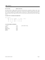
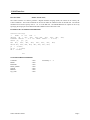
ABEL Interface
INVOCATION:
SIMULATOR abel ;
The VGEN interface to ABEL generates a TEST_VECTOR table which is compatible with ABEL's syntax. Since
VGEN allows only single characters for states, the P, C and X must be declared in the body section of the ABEL
file. No timing is supported since the ABEL simulator is functional only. VGEN Comments automatically have a "
character inserted in front of them in the test vector file. Busses must be declared in the body section of the ABEL
file also.
EXAMPLE OF VECTOR FILE GENERATED:
test_vectors
([p1, p2, p3, dbus]) -> [out1,
[1, 1, 1, ^hff] -> [1, 1];
[0, 1, 0, ^haa] -> [0, 1];
[0, 0, 0, ^hcc] -> [0, 0];
etc.
out2])
VGEN FEATURES SUPPORTED:
Comments
Header
Busformat
Define_Header
Outputs
Bidirects
VGEN Interfaces Guide
- YES.
- YES.
- YES.
- YES.
- YES.
- YES.
" prefix added to string.
Page 3
ADVANSIM_1076 Interface (DAZIX)
INVOCATION:
SIMULATOR advansim_1076 (or advansim_1076_te);
The VGEN compiler creates a VLAIF-compatible file for interfacing with the ADVANSIM_1076 logic simulator
from Intergraph Electronics. This is a tabular file format which supports only binary radix for busses. The
advansim_1076_te option generates the newer time_event format which also supports hex and octal bus formats.
All pins should be defined with the VGEN INPUTS declarative. The stimulus file is directly loadable into the
ADVANSIM_1076 simulation environment. Pins are listed explicitly in the file, but they must also be defined
identically in your SOM Control File.
For pin names which are to be represented as active low in the ADVANSIM_1076 environment, the following
VGEN naming conventions can be used and the interface will automatically perform the indicated mapping:
VGEN Source File
VLAIF file
pin*
bus*[4]
bus*[7:0]
->
->
->
pin~
bus(4)~
bus(7:0)~
EXAMPLE OF VECTOR FILE GENERATED:
$DATA_HEADER$
$TYPE$
I/O
$FORMAT$
TIME_VALUE
$TOTAL_COLUMNS$
10 6
$BASE$
D B
$FIELD$ 1
PIN1 1
$FIELD$ 2
PIN2 2
. . .
$END$
0
0000000
100
1000000
200
0000001
240
1000001
etc.
VGEN FEATURES SUPPORTED:
Comments
Header
Busformat
Define_header
Outputs
Bidirects
Sys_clock
Page 4
- (YES).
- YES.
- YES.
- YES.
- NO.
- NO.
- NO.
Use only at top of file and enclose in /*..*/ .
Only once at top of file.
Only with advansim_1076_te option.
Replaces everything above $END$ .
VGEN Interfaces Guide
CADAT Interface
INVOCATION:
SIMULATOR cadat ;
The VGEN interface to CADAT generates a Digital Stimulus Language (DSL) file which can be read by the
CADAT simulator. The TITLE command can be used to define the CIRCUIT name in the DSL file. The UNITS
command can be used to specify units of .1 or .01 in the DSL file. The SENSE DELAY for outputs can be set by
specifying the output pins with a PINTYPE STB command in the VGEN source file.
EXAMPLE OF VECTOR FILE GENERATED:
CIRCUIT testchip;
/*
DATE: 12 Oct 1991 */
VECTOR
db = db7, db6, db5, db4, db3, db2, db1,
TIMEDEF PERIOD = 9.9 NS SENSE DELAY = 8.9 NS;
INPUT p1, p2, p3;
BUS db7, db6, db5, db4, db3, db2, db1, db0;
DRIVE db7, db6, db5, db4, db3, db2, db1, db0;
p1 = 0:20NS;
p2,p3 = 1:20NS;
db = Z:20NS$
db0;
etc.
VGEN FEATURES SUPPORTED:
Comments
Header
Busformat
Define_Header
Outputs
Bidirects
Sys_clock
VGEN Interfaces Guide
- YES.
- YES.
- YES.
- YES.
- YES.
- YES.
- YES.
surround by /* . . */
Page 5
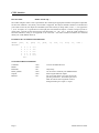
CUPL Interface
INVOCATION:
SIMULATOR cupl ;
The VGEN compiler creates a source specification file containing the appropriate stimulus and expected output data
for the CUPL simulator. Only binary vector format is supported. Pins may be defined as INPUTS or OUTPUTS in
your VGEN source file, the outputs are identified by the states which you assign them (i.e H, L, *, Z as opposed to
1, 0, etc. for inputs). It is a good idea to list the input pins first and then the outputs. In order to assign a pin the 'C'
(clock) state, you must use the explicit binary radix designator (e.g. clk = 'C'b; ). Since the CUPL simulator is a
functional simulator, timing is not supported in the vector file. All VGEN comment statements are translated
directly into CUPL $MSG directives.
EXAMPLE OF VECTOR FILE GENERATED:
ORDER: pin1, %1,
VECTORS:
0 0 0
0 0 0
0 1 1
1 1 1
1 1 0
etc.
pin2,
0
C
C
0
C
X
L
H
H
H
%1,
pin3,
%1,
clk,
%3,
out1,
%1,
out2 ;
X
L
L
L
H
VGEN FEATURES SUPPORTED:
Comments
Header
Busformat
Define_Header
Outputs
Bidirects
Page 6
- YES.
- YES.
- NO.
- YES.
- YES.
- NO.
Converts to $MSG directive.
Only binary.
Can be used to customize your ORDER format.
State assigned indicates outputs.
Do not use this directive as it will result in the
pin being listed twice. For bidirect pins, list as
INPUTS and use state assignment values to
distinguish when pin is input vs. output.
VGEN Interfaces Guide
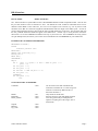
HILO Interface
INVOCATION:
SIMULATOR hilo ;
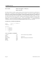
The VGEN interface to System HILO creates a WAVEFORM module in DWL-compatible format. This file lists
the pin state transition events in absolute AT time. The default bus radix is BIN but individual busses can be
defined as either HEX or OCT radix also. If a bus is to be assigned a non-1/0 state (e.g. Z or X), then its radix
should be left as BIN to avoid state assignments like HEX ZZ55 which is illegal in the DWL syntax. In order to
create a background free-running system clock the SYS_CLOCK declarative can be used. The pin name used with
the SYS_CLOCK declarative should not appear in the INPUTS list. Another way to create processes outside the
main block is to use the COMMENT statement at the top of your source file. The COMMENT text string (which
can span multiple lines) also allows you to insert control commands such as STROBEOFF in your stimulus file.
EXAMPLE OF VECTOR FILE GENERATED:
WAVEFORM filename ;
TITLE
Stimulus pattern file
ENDTITLE ;
INPUT pin1 pin2 bus[7:0] ;
BIDIR pin3 ;
BASE BIN ;
STROBEOFF ;
begin
AT 0
pin1 := 0 pin2 := 0 bus := HEX 00 pin3 := 0
pin3 = X;
AT 100 pin1 := 1;
AT 200 pin1 := 0;
AT 280 bus := HEX 5A pin3 := Z;
AT 300 pin3 = 1;
STROBE();
AT 360 pin2 := 1;
etc.
VGEN FEATURES SUPPORTED:
Comments
- YES.
Header
Busformat
Define_Header
- NO.
- YES.
- YES.
Outputs
Bidirects
Sys_clock
- YES.
- YES.
- YES.
VGEN Interfaces Guide
Can be used to insert both commands and
comments in stimulus file. For text string to be
treated as a comment by HILO the first 2
characters should be **.
Only useful for tabular files.
Each bus can have radix individually defined.
Text string (which may be multiple lines)
replaces everything above the "begin" line in
stimulus file.
Page 7
IKOS Interface
INVOCATION:
SIMULATOR ikos (or ikos_b);
VGEN creates either an ASCII .wav file or a binary .wav file (ikos_b) for the IKOS simulation accelerator. The
ASCII file can then be converted to a binary file using the IKOS utility " wls ", and then be loaded directly into the
IKOS environment, while the binary file is ready for direct loading. This interface supports all 4 types of pin
declarations: INPUTS, OUTPUTS, BIDIRECTS and SYS_CLOCK. Each of these pin types results in uniquely
formatted pin traces in the vector file. These must match the way the pins are defined in the circuit. When pins are
declared with the BIDIRECTS statement, the input version of the pins are assigned states using the pin name,
whereas the output versions of the pins are assigned expected output states using the pin names with a .o suffix.
For example:
BIDIRECTS
pina = 'Z';
pina.o = 1;
pina;
{ drive Z }
{expect 1 }
Each pin declared with BIDIRECTS will create two traces in the vector file. One for the input version and one for
the output version.
The SYS_CLOCK declarative will create a clock pin on the IKOS system clock trace with timing as defined in the
statement. The file format for the IKOS vector file is somewhat cryptic and should not be edited without detailed
knowledge of the format. The VGEN compiler, for this reason, inhibits the inclusion of any text from the
HEADER, DEFINE_HEADER and COMMENTS declaratives. The bus radixes are pre-defined as HEX and hence
the declarative BUSFORMAT has no effect. This release supports the IKOS Release 4.02 software.
VGEN FEATURES SUPPORTED:
Comments
Header
Busformat
Define_header
Outputs
Bidirects
Sys_clock
Page 8
- NO.
- NO.
- NO.
- NO.
- YES.
- YES.
- YES.
VGEN Interfaces Guide
LASAR Interface
INVOCATION:
SIMULATOR lasar ;
The VGEN interface to LASAR creates two separate files. The first file contains the state information for a
HIGHSPEED simulation, while the second file (with suffix .tim) contains the timing information for the simulation.
The automatically-generated .tim file can be incorporated into the stimulus data by adding an INCLUDE
'filename.tim' to the top of the stimulus file using the VGEN COMMENT command. If no pin timing is specified in
the VGEN source file, then the compiler uses default timing for defining PHASEs and WINDOWs on input, bidirect
and output pins. The time specified in the VGEN CYCLE command becomes the CLOCK value in the LASAR .tim
file. In order to define non-default timing on pins in the source file, use the VGEN PINTYPE commands. Pin
behavior and timing is mapped from the PINTYPE specification to LASAR timing (TSET) syntax as follows:
VGEN
LASAR
NRZ
$NRET
RZ
$RZERO
RO
$RONE
RX Z
$ROFF
RC
$RCOMP
STB
WINDOW strobe timing
BIDR
PHASE timing and WINDOW strobe timing
Input pins should have their timing defined with one of the first 5 PINTYPES listed above. Output pins should have
their strobe timing specified with the PINTYPE STB command. Since the strobe (STB) in VGEN only defines a
single time point at which to examine the output data, for LASAR the compiler defines the strobe window as being
from the STB time to 5NS before the end of the cycle.
When using PINTYPE commands in the VGEN source file to define pin timing and behavior for the LASAR
interface, do not enable the timing with the PINTIMING ON command. This will keep the timing information
separate from the state information, which is what we want for LASAR. The timing defined in the .tim file can also
easily be edited if necessary. When compiling for other simulators where the timing information must be
incorporated directly into the state data, such as those with tabular formats, the PINTIMING ON command would be
used.
LASAR commands and comments which are not automatically placed in the stimulus file can be added with the
VGEN COMMENT command. VGEN intentionally leaves out certain LASAR commands in order to give the user
more flexibility.
For example, a typical VGEN source file to be compiled for the LASAR simulator would have the following
commands at the top of the file:
comment "INCLUDE 'filename.tim' ";
comment "HIGHSPEED";
comment "USE TSET 1";
comment "CPP = 1" ;
Where the 'filename.tim' is either the auto-generated timing file or one edited by the user. In order to pass a
comment to the LASAR stimulus file simply begin the comment string with an !
VGEN Interfaces Guide
Page 9
LASAR Interface (continued)
VGEN FEATURES SUPPORTED:
Comment
- YES.
Header
Busformat
Define_header
Outputs
Bidirects
Sys_clock
- NO.
- YES.
- YES.
- YES.
- YES.
- NO.
Page 10
First character must be ! for comment,
otherwise its a command.
VGEN Interfaces Guide
LSI Logic Interface
INVOCATION:
SIMULATOR lds (or lds_i) ;
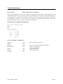
The VGEN compiler creates a PATTERN file of the stimulus pin states for direct loading into the LDS (MDS)
simulation environment with the TPATTERN command. The format of the file is tabular with support for
COMMENT and HEADER commands from the VGEN source file. Individual bus radixes may be specified with
the BUSFORMAT command. The pattern file contains purely stimulus data; the pin order and radixes must be
defined in your SCL TPATTERN command so they match the way you define them in your VGEN source file. In
the time field of the vector file, either absolute or incremental time may be used. Invocation with "SIMULATOR
lds;" specifies absolute time, whereas "SIMULATOR lds_i;" specifies incremental time.
EXAMPLE OF VECTOR FILE GENERATED:
00.55.00.0000
01.55.01.0000
00.55.01.0000
00.AA.2F.0101
01.AA.2F.0101
00.CD.14.1100
etc.
/0
/80
/100
/150
/200
/280
VGEN FEATURES SUPPORTED:
Comments
Header
Busformat
Define_header
Outputs
Bidirects
Sys_clock
VGEN Interfaces Guide
- YES.
- YES.
- YES.
- YES.
- NO.
- NO.
- NO.
First character of string must be *.
Busses can have radixes individually defined.
Placed at top of file.
Page 11
LSIM Interface
INVOCATION:
SIMULATOR lsim ;
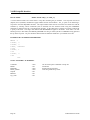
The VGEN interface for LSIM creates an object code file. This file provides fields for both input pin states and
expected output states, and hence pins may be declared as INPUTS, OUTPUTS or BIDIRECTS pintypes in your
VGEN source file. BIDIRECTS will be listed in the LSIM pinlist twice, once under "INPUT" and once under
"OUTPUT" (the .o suffix will be dropped). Although VGEN does not allow you to include signal parameters in the
signal list (such as to=20 - a timing offset), the equivalent can be accomplished using the PINTYPE declarative in
VGEN, which will generate the individual vectors with this timing. Another alternative would be to create your
own header with desired pin names and parameters using the DEFINE_HEADER command in your VGEN source
file.
EXAMPLE OF VECTOR FILE GENERATED:
CODEFILE;
INPUTS pin1, pin2, pin3, bus[7:0];
OUTPUTS out1;
CODING(ROM)
@0
<00000000000 >.;
@50 <11000000000 >0;
@125 <01011100001 >1;
etc.
VGEN FEATURES SUPPORTED:
Comments
Header
Busformat
Define_header
Outputs
Bidirects
Sys_clock
Page 12
- NO.
- NO.
- NO.
- YES.
- YES.
- YES.
- NO.
Not allowed in LSIM object file.
Only Binary format.
Replaces everything above CODING(ROM) line.
VGEN Interfaces Guide
MACH (Zycad) Interface
INVOCATION:
SIMULATOR mach ;
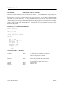
VGEN interfaces with the MACH 1000 logic simulation accelerator by creating a Sentry file containing the
stimulus. This file must then be processed with the MACH tool Sen2ir. Vector files for both logic simulation and
fault simulation can be created using VGEN. All pins should be declared with the INPUTS statement in your
VGEN source file. Busses may have their radixes defined individually using the BUSFORMAT declarative.
EXAMPLE OF VECTOR FILE GENERATED:
pin1;
pin2;
bus[3], bus[2],
$
0
0 0
100
1 0
120
0 0
180
0 0
200
1 0
250
0 1
300
0 0
etc.
bus[1], bus[0] H;
0
0
0
A
A
A
5
VGEN FEATURES SUPPORTED:
Comments
- YES.
Header
Busformat
Define_header
Outputs
Bidirects
Sys_clock
- YES.
- YES.
- YES.
- NO.
- NO.
- NO.
VGEN Interfaces Guide
Use # as first character in text string to be
treated as comment.
Radix can be defined for each bus individually.
Replaces everything above $ line.
Page 13
MAX+PLUS Interface
INVOCATION:
SIMULATOR maxplus ;
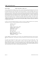
The VGEN interface for MAX+PLUS creates a Vector File containing the input (and optionally the expected
outputs) data. The compiler automatically uses the MAX+PLUS "Group Create" command to define busses. The
data is formatted in the Pattern Section using absolute time stamps. The radix for busses is defined with the
BUSFORMAT declarative.
EXAMPLE OF VECTOR FILE GENERATED:
RADIX HEX;
GROUP CREATE db = db7 db6 db5 db4 db3 db2 db1 db0;
INPUTS pin1 pin2 pin3 db;
OUTPUTS o1 o2;
PATTERN
0> 0 0 0 00 = X X
100> 1 0 0 23 = 1 0
200> 0 0 0 23 = 1 0
300> 1 0 0 AC = 0 0
etc.
VGEN FEATURES SUPPORTED:
Comments
Header
Busformat
Define_Header
Outputs
Bidirects
- YES.
- YES.
- YES.
- YES.
- YES.
- YES.
Sys_clock
- NO.
Page 14
Delineate comments with % character.
Make your own top section.
Can specify expected output states.
Can specify input and expected output states.
Outputs referred to with .o suffix.
VGEN Interfaces Guide
MENTOR Logfile Interface
INVOCATION:
SIMULATOR mentor (or mentor_ng) ;
The VGEN compiler produces stimulus files under two formats for Mentor's Quicksim logic simulator. The first
format is a Mentor Logfile, which is the most compact and efficient format for stimulus. This file can be loaded
directly into the Quicksim environment using the Quicksim READ FORCe Logfile command. Busses and
GROUPS defined in the VGEN source file are used in the Logfile and should be declared in your Quicksim
environment with a DEFine Bus command. Invoking the Mentor Logfile interface with mentor_ng (instead of
mentor) will inhibit the use of any GROUP names that you may have defined in your VGEN source file. All pins
should be declared using the INPUTS statement in your VGEN source.
In Logfile format, driven signals can be assigned states 0, 1 or X, resistive states are O, I and U, and high impedance
states are H, L and *. Any pin can be assigned any of these states. For busses and groups, only the binary bus
format is supported in the Logfile. In order to accommodate the fractional time units used in the Logfile, the VGEN
UNITS declarative should be used (default is integer time units).
EXAMPLE OF VECTOR FILE GENERATED:
D
D
D
D
D
D
D
D
t
s
s
s
s
t
s
t
s
s
t
s
s
t
pin1 1 X
pin2 2 X
pin3 3 X
bus(3) 4
bus(2) 5
bus(1) 6
bus(0) 7
bus(3:0)
0.0
1 0
2 0
3 0
8 0000
80.0
1 1
100.0
2 1
1 0
150.0
2 0
8 1010
200.0
etc.
X
X
X
X
8 XXXX
VGEN Interfaces Guide
Page 15
MENTOR Logfile Interface (continued)
VGEN FEATURES SUPPORTED:
Comments
- YES.
Header
Busformat
Define_header
Outputs
Bidirects
Sys_clock
- NO.
- NO.
- YES.
- NO.
- NO.
- NO.
Page 16
Can only be used to insert legal commands.
Comments are not allowed in Logfile.
Only Binary.
Replaces everything above t 0.0 .
VGEN Interfaces Guide
MENTOR Force file Interface
INVOCATION:
SIMULATOR mentor_force (or mentor_force_ng)
[param_list];
The second Mentor file format supported by the VGEN compiler is the Mentor Force file. This is similar to the
Logfile, except that it is less cryptic, and hence tends to be somewhat larger. On the other hand, it is easier to follow
and provides more flexibility for commenting and inserting in-line commands. Here, the optional parameters are:
VERSION = "8.x", VHDL ;
If present, the VERSION="8.x" parameter causes SETUP to be added to the front of the RADIX command in the
FORCe file. Also, if the VHDL parameter is specified, the S and R strength designators are inhibited from the states
in the file.
In order to maintain compatibility with the single character states used in the Mentor Logfile format, the following
state mapping is performed by the VGEN compiler:
VGEN State
0, 1, X
O, I, U
L, H, *, Z
->
->
->
Force File State
0S, 1S, XS
0R, 1R, XR
0Z, 1Z, XZ, XZ
(strong)
(resistive)
(hi impedance)
When assigning states to bus pins, you should not mix different strengths on pins of the same bus. The single radix
defined with the BUSFORMAT declarative applies to all busses. The use of group names declared with the VGEN
GROUP declarative is inhibited in the Force file when the "SIMULATOR mentor_force_ng; "invocation is used.
Time units can be modified using the UNITS declarative, to .1 or .01. Busses used should be defined in the Force
file by passing COMMENT strings to the top of the file so that they are consistent with how they are used in the
VGEN source file. For example:
COMMENT "DEFINE BUS GP1 pin1 pin2 pin3 -COMBINE";
COMMENT strings can also be used to place other Mentor commands in the Force file such as "LIST", "BREAK",
"CHECK" etc. Background periodic clocks can be specified using the VGEN SYS_CLOCK declarative, or by
simply inserting appropriate commands in your Force file to define the desired clock using VGEN COMMENT
strings.
Pin attributes (quoted strings which follow pin names in the INPUTS, OUTPUTS and BIDIRECTS statements) can
be used to specify the Strength Type for those pins in the FORCe file. For example:
INPUTS pin1 "-Fixed", pin2 "-Wired", pin3;
This declares 3 pins which will appear in the FORCe file as:
FORCe pin1 1S 225 -Fixed -A
FORCe pin2 0S 225 -Wired -A
FORCe pin3 1S 225 -A
VGEN Interfaces Guide
Page 17
MENTOR Force file Interface (continued)
EXAMPLE OF VECTOR FILE GENERATED:
RADIX BIN
FORCe db XXXXXXXXZ 0 -A
FORCe pin1 0S 0 -A
FORCe pin2 0S 0 -A
FORCe pin1 1S 100 -A
FORCe pin1 0S 160 -A
FORCe db 11001100S 200 -A
FORCe pin2 1R 220 -A
FORCe pin1 1R 220 -A
etc.
VGEN FEATURES SUPPORTED:
Comment
- YES.
Header
Busformat
Define_header
- NO.
- YES.
- YES.
Outputs
Bidirects
Sys_clock
- NO.
- NO.
- YES.
Page 18
First character of string should be '#' to be
treated as comment by QuickSim. Otherwise
can be used to insert commands.
Single radix for all busses.
Replaces RADIX line; string can be multiple
lines.
Creates CLOCK PERIOD command followed by
two FORCe statements on the sys_clock pin to
generate the specified timing.
VGEN Interfaces Guide
OrCAD Interface
INVOCATION:
SIMULATOR orcad ;
Compiling a VGEN source file for OrCAD results in the creation of 3 files. The first is a Test Vector Source (.tvs)
file compatible with the OrCAD VST simulator, which will be stored in outfile.tvs. This file uses a fixed format for
the time and vector data. The time tag starts in column 1 and is 10 digits wide. The pin data columns start in
column 13 and each pin is separated by a blank column unless the pin has been defined as a bus in the VGEN source
file. The order of pins in this file is the same as the order in which they were defined in the VGEN source file.
Using the HEADER command in the VGEN source file will cause a vertical pin name listing to be included in the
.tvs file above their respective columns. Comments can be inserted in the vector file using the COMMENTS
command in VGEN. Text to be inserted as comments should have a ';' character in the first column. For example,
the VGEN command:
COMMENT "; The bus tests begin here";
will place the quoted text in the .tvs file at the location in the vectors corresponding to where it is encountered in the
VGEN source program.
The second file created by VGEN is a stimulus file containing the TESTVECTOR_SPECIFICATION information.
This consists of information for the simulator on the format of the vector lines in the .tvs file. This file is saved
under the name outfile.ast. The CONTEXT field is assumed to be '.' (top level of the design hierarchy).
The third file created is the Trace file outfile.trc. This file contains the TRACE_SPECIFICATION information for
the simulator. All pins defined in the VGEN source file are traced unless they were defined with a "NOTR"
attribute in the source file. An example of this would be:
inputs clk, bus [7:0], am "NOTR", pin1, pin2;
Here the pin'am' will not be included in the Trace file. Busses defined in the VGEN source file will be traced as
busses with the radix defined using the BUSFORMAT command in the source file.
EXAMPLE OF VECTOR FILE GENERATED:
;
;
;
;
;
;
0000000000
0000000100
0000000200
0000000300
0000000400
0000000500
etc.
p
i
n
4
p
i
n
3
0
0
0
0
0
0
p
i
n
2
0
0
0
0
0
0
VGEN Interfaces Guide
p
i
n
1
p
i
n
0
0
0
0
1
1
1
dddddddd c
bbbbbbbb l
uuuuuuuu k
ssssssss
76543210
0
0
0
0
0
0
0
0
0
0
0
0
00000000
00000000
00000000
01010101
01010101
01010101
0
1
0
0
1
0
Page 19
OrCAD Interface (continued)
VGEN FEATURES SUPPORTED:
Comments
Header
Busformat
Define_header
Outputs
Bidirects
Sys_clock
Page 20
- YES.
- YES.
- NO.
- YES.
- NO.
- NO.
- NO.
Start comment strings with a ';'.
OrCAD only supports Binary vectors.
OrCAD vector files treat all pins the same.
OrCAD vector files treat all pins the same.
VGEN Interfaces Guide
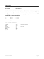
QSIM Interface
INVOCATION:
SIMULATOR qsim [param] ;
The VGEN compiler creates a script-formated QSIM file. The optional parameter [param] can be the name of a file
which contains additional header information. The contents of this file is inserted into the QSIM output file just
prior to the start of the vector data.
EXAMPLE OF VECTOR FILE GENERATED:
siv clk ’b1
siv dbus ’b00000000
step 25
siv clk ’b0
siv addr ’b10101111
step 20
test omb ’b1101
. . .
etc.
VGEN FEATURES SUPPORTED:
Comments
Header
Busformat
Define_header
Outputs
Bidirects
Sys_clock
VGEN Interfaces Guide
- YES.
- YES.
- NO.
- NO.
- NO.
- NO.
- NO.
First character in string must be a '#'.
Binary only.
Page 21
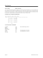
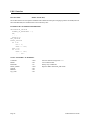
SILOS Interface
INVOCATION:
SIMULATOR silos ;
The VGEN SILOS interface generates a tabular file which uses the .PATT data format. The .PATT statement lists
the pin names in the order which you defined them in your VGEN source program, busses are listed as the single
bus name with no subscripted bits. VGEN will automatically create the appropriate SILOS bus declarations before
the .PATT line. The pattern data uses the absolute time format, with up to 9 digits of time.
EXAMPLE OF VECTOR FILE GENERATED:
.HEX addr=addr3,addr2,addr1,addr0
.PATT addr m3 m2 m1 m0 rw exp d7 d6 d5 d4 d3 d2 d1 d0
0 0 000 0 1 11110000
100 0 000 1 1 11110000
200 0 000 0 1 11110000
300 5 010 0 1 10101010
400 5 010 1 1 10101010
500 7 010 0 1 00001111
etc.
VGEN FEATURES SUPPORTED:
Comments
Header
Busformat
Define_Header
Outputs
Bidirects
Sys_clock
Page 22
- YES.
- YES.
- YES.
- YES.
- NO.
- NO.
- NO.
Start comment strings with a '$'.
Not distinguished in .PATT data.
Not distinguished in .PATT data.
VGEN Interfaces Guide
SPICE Interface
INVOCATION:
SIMULATOR spice [param_list] ;
VGEN can interface a set of stimulus data to the SPICE analog simulator by producing a set of Piecewise-Linear
(PWL) waveform descriptions for the pin transitions. The optional "param_list" which can be specified at
invocation can include any of the following SPICE-specific parameters :
UNITS = units,
TechFile = "filename",
TRISE = value,
TFALL = value,
VIL = value,
VIH = value,
TRIZ = value ,
VREF_NODE = node_number;
Where "units" can be FS, PS, NS, US or MS; "filename" is the name of the technology file containing SPICErelated parameters; and "value" can be either MIN, TYP, MAX, or a specific value. When either MIN, TYP or
MAX is assigned to a parameter (e.g. TRISE = MAX), the max value for this parameter as listed in the techfile is
used. If a specific value is assigned to a parameter (e.g. VIL = 0.25), then this value overrides the value for this
parameter in the techfile. The VREF_NODE parameter defaults to node 0 if not specified. Specific values for all
parameters can be specified in the param_list, in which case no techfile need be specified. An example of invoking
the SPICE interface with a parameter list would be:
SIMULATOR spice units = NS, Techfile = "fast.tech", trise=typ,
tfall=typ, vil=0.15, vih=2.55, triz=3.65;
When used, the techfile has the following format:
*
trise =
tfall =
VIL =
VIH =
TRIZ =
MIN
1.00E+00
1.50E+00
0.20E+00
2.40E+00
3.25E+00
:
:
:
:
:
MAX
2.00E+00
2.80E+00
0.20E+00
2.60E+00
3.25E+00
UNITS
: ns
: ns
: V
: V
: V
Within the SPICE PWL stimulus file, a voltage source is created for each pin, with the names being V1, V2, .. Vn
where n is the total number of pins in the stimulus file. Each voltage source is referenced across a node name (or
node number) and the VREF_NODE which defaults to node 0 (assumed to be VSS, 0V). Thus, for the INPUTS
statement below, the voltage source for the first pin would be as shown:
INPUTS pin1, pin2, pin3;
V1 pin1 0 PWL ( . . . )
{ in VGEN source file }
{ in SPICE stimulus file }
In order to provide more flexibility is specifying the nodes for voltage sources, specific node numbers can be
specified for use instead of node names. This is accomplished by following the pin names with a node number
attribute in quotes when defining the pins in the VGEN source file. Modifying the above example to do this would
result in:
VGEN Interfaces Guide
Page 23
SPICE Interface (continued)
INPUTS pin1 "22", pin2 "32", pin3 "44" ;
V1 22 0 PWL ( . . . )
{ VGEN source }
{ SPICE stimulus }
In addition to converting digital signals into their SPICE Piecewise-Linear equivalents using technology-related
parameters specified, VGEN also supports the generation of Piecewise-Linear continuous analog voltages. This is
done with a new command in VGEN, whose syntax is as follows:
ANALOG busname [, VMAX = value] [, VMIN = value] ;
Where "busname" is the name of a vectored bus previously defined with an INPUTS command, the optional
parameters VMAX and VMIN specify the voltage range over which the analog signal will vary. If no VMIN or
VMAX parameter is specified, then the VIL and VIH values will be used from the SPICE param_list. The number
of bits defined for the bus determines the resolution of the analog signal within the voltage range. An example is
given below:
INPUTS pin1 "12", vbus[7:0] "33" ;
ANALOG vbus vmin = 0.50, vmax = 5.50;
Here, the 8-bit bus "vbus" is defined as an analog pin, with a voltage range of 5.0 volts (between 0.5 and 5.5).
Assigning vbus a value of 0 would set it to 0.5 volts, a value of 'FF' would set it to 5.5 volts and a value of '0F'
would set it to 3.0 volts. The vbus bus is treated the same way as any other bus in the VGEN source file, with the
conversion taking place only during output formatting. The voltage translation from digital values to an analog
voltage works the same way an A/D converter would.
EXAMPLE OF VECTOR FILE GENERATED:
V1 12 PWL (
+
0.00000000e+00
+
2.00000000e-09
+
1.00000000e-07
+
1.01000000e-07
. . . etc.
)
V2 15 PWL (
. . . etc.
6.000000e-01
2.200000e+00
2.200000e+00
6.000000e-01
VGEN FEATURES SUPPORTED:
Comments
Header
Busformat
Define_Header
Outputs
Bidirects
Sys_clock
Page 24
- NO.
- NO.
- NO.
- NO.
- NO.
- NO.
- NO.
VGEN Interfaces Guide
SUSIE Interface
INVOCATION:
SIMULATOR susie ;
VGEN provides an interface to the SUSIE logic simulator. This interface uses the SUSIE 6 vector format. This is
the most flexible vector format and supports all of the timing features of VGEN.
EXAMPLE OF VECTOR FILE GENERATED:
SCALE 100 NS
ppppppc
iiiiiil
nnnnnnk
123456.
0 ns
0000000
100 ns
0000010
240 ns
0101011
etc.
(ASCII timing file format)
VGEN FEATURES SUPPORTED:
Comments
Header
Busformat
Define_Header
Outputs
Bidirect
Sys_clock
VGEN Interfaces Guide
- YES.
- YES.
- NO.
- YES.
- NO.
- NO.
- NO.
First char. in string must be ';'.
Always binary.
Create your own pin list.
Page 25
TEGAS Interface
INVOCATION:
SIMULATOR tegas (or tegas_i) ;
The VGEN compiler creates a tabular TESTPATT file for interfacing with the TEGAS logic simulator. The time
field can be either absolute (tegas) or incremental (tegas_i).
EXAMPLE OF VECTOR FILE GENERATED:
IVECTOR PIN1, PIN2, PIN3, BUS-3, BUS-2, BUS-1, BUS-0 $
TESTPATT $
0000000
0
1000000
100
0000011
120
0101100
150
0010011
200
etc.
VGEN FEATURES SUPPORTED:
Comments
Header
Busformat
Define_header
Outputs
Bidirects
Sys_clock
Page 26
- YES.
- YES.
- NO.
- YES.
- NO.
- NO.
- NO.
First character in string must be a '*'.
Binary only.
Replaces everything above TESTPATT line.
VGEN Interfaces Guide
TIMEMILL (EPIC) Interface
INVOCATION:
SIMULATOR timemill or epic (timemill_nsvt) [param];
Two files are created by VGEN for interfacing with the TIMEMILL (and POWERMILL) logic simulator. The first
is a command file which invokes the second file, a tabular vector file, loadable directly into the simulation
environment. The name of the command file can be specified with the special [COMMAND_FILE " filename" ;]
statement or default to a .cmd suffix of the target file name. The second file is either a .vec file (timemill or epic) or
a nsvt file (timemill_nvst). If the ’epic’ invocation is used, an EPIC .out file is also generated.
Radixes can be specified for individual busses using the VGEN BUSFORMAT declarative. The COMMENT
statement can be used to insert either commands (e.g. COMMENT "slope 2.5 " ; ) or comments (e.g. COMMENT
"; beginning memory tests " ; ) in the vector file. The VGEN UNITS declarative can be used to modify the time
units to .1 or .01 . Spaces between vector columns can be specified by using double commas between pin names
when listing them in the INPUTS, OUTPUTS or BIDIRECTS statements (e.g. INPUTS pin1, pin2,, busa,, busb,
p3, p4, p5; ).
An optional parameter can be specified which tells VGEN how you want the vector notation in the output file. The
syntax is:
BUS_NOTATION = "LrR";
Where L is the desired Left bus delimeter, r is the bus range character(s) and R is the right bus delimeter, For
example:
SIMULATOR epic bus_notation="<:>" ;
would result in busses in the .cmd file (and .out file) being listed as bus<a:b>. The bus range may be 1 or 2
characters (e.g. "<..>") , the default bus_notation is "[-]".
EXAMPLE OF VECTOR FILE GENERATED:
radix 1144111133
io iiiiiiii00
0 00 00
100 01 00
120 00 5A
200 01 5A
220 00 CF
etc.
0000
0000
0101
0101
1100
00
00
75
75
42
VGEN FEATURES SUPPORTED:
Comment
- YES.
Header
Busformat
Define_header
Outputs
Bidirects
Sys_clock
- YES.
- YES.
- YES.
- YES.
- YES.
- NO.
VGEN Interfaces Guide
First character in string must be a ';'. Otherwise
can be used to insert commands.
Individual radixes may be specified.
Replaces radix & io lines.
Page 27
TOSHIBA Interface
INVOCATION:
SIMULATOR toshiba (or toshiba_nw);
or
SIMULATOR tstl2;
The VGEN interface for Toshiba's simulator generates functional test pattern data coded in their standard TSTL or
TSTL2 format. The toshiba_nw version inhibits line-wrap at column 72. For the first two options (toshiba and
toshiba_nw), the format produced is TSTL compatible. If the third option is used (tstl2) then the file generated is in
TSTL2 format. Pins may be declared with the INPUTS, OUTPUTS or BIDIRECT statements in your VGEN source
file and the spacing between pins in the tabular listing can be controlled by putting double commas (,,) in front of
pins which you wish to have a space precede. The timeset header information is generated by specifying VGEN
pintypes PP, NP, DT, STB and BIDR for all pins - however, the PINTIMING should not be enabled during
compilation. Finally, the title string of the header can be specified with a TITLE " . . " ; command and the width
of the output strobes can be specified with the STROBE_WIDTH command in the VGEN source file.
EXAMPLE OF VECTOR FILE GENERATED:
TITLE
Vectors for ADDER123 ;
CYCLE
125 ;
TIMESET(1) DT, 30 ;
. . .
TESTPATT ;
0 0 ZZZZZZZZ;
1 0 ZZZZZZZZ;
0 1 ZZZZZZZZ;
0 1 HLHLLHHH;
etc.
VGEN FEATURES SUPPORTED:
Comments
Header
Busformat
Define_Header
Outputs
Bidirects
Sys_clock
Page 28
- YES.
- NO.
- YES.
- YES.
- YES.
- YES.
- NO.
Precede comment strings with REM.
TSTL2 only
Replaces everything above TESTPATT.
VGEN Interfaces Guide
TSSI Interface
INVOCATION:
SIMULATOR tssi ;
The VGEN interface for TSSI produces two files. The first is a signal definition file which will have a .sdf suffix on
the file name, and the second is the vector file. All pin state translations to TSSI states, and the merging of any
bidirectional state data happens automatically in this interface. Thus, it is not necessary to use either the
STATE_TRANS or MERGE_BIDIRECTS commands. In order for these automatic state translations and mergings
to work properly, use the state characters 0, 1, Z and X when assigning states to pins.
EXAMPLE OF VECTOR FILE GENERATED:
0.0
8.5
23.4
.
N N N N N Z Z X X X
D D D U U Z Z X X X
D D D U D D D H L X
.
.
etc.
VGEN FEATURES SUPPORTED:
Comments
Header
Busformat
Define_Header
Outputs
Bidirects
Sys_clock
VGEN Interfaces Guide
- YES.
- YES.
- No.
- NO.
- YES.
- YES.
- NO.
First character must be #.
Binary only.
Page 29
UDF - User Defined Format
INVOCATION:
SIMULATOR udf "format-string" [param_list] ;
In addition to the canned output formatters which produce simulation data files for specific target logic simulators,
the VGEN now also supports a User-Defined output vector format. This format must be of the tabular format type;
i.e., a time stamp and complete set of pin state data comprises each line. This option is invoked with the
SIMULATOR command as follows:
SIMULATOR UDF "format-string" [,bit_sep='c']
[,include_bi_outs];
Where the "format-string" specifies the actual format of each vector line, bit_sep='c' can be optionally used to
change the character used for separating bits in the vector (this defaults to a blank, and is invoked by using double
commas -,,- between pin names where you wish to have a separator), and the optional include_bi_outs forces the
bidirectional output pin states to be listed as separate data columns.
Within the "format-string", there can be two types of information. These are variable data and hard-character data.
Hard-character data is simply copied exactly as listed to the output vector. Variable data is of two sub-types; the
first is the time variable (which always begins with the % character), and the second is the pin states variable
($states). The following are the variable data forms supported by UDF:
•
•
•
•
•
%[n]at
n digits of absolute integer time stamp. If no n is specified then field length will be exactly as wide
as needed for current time stamp. If n is specified, time stamp will be right-justified in field; if -n is specified,
time stamp will be left-justified in field.
%[n]af
n digits of floating-point absolute time stamp. Same rules as above apply to n. In addition, n can be
used to specify the number of decimal points after the '.' to be used in the time stamp in a manner identical to the
C Language. For example %-10.2af would specify a left-justified 10 character field with 2 digits after the
decimal point. This time format would only normally be used if the UNITS command had been used in the
VGEN command file to specify decimal fraction time units.
%[n]dt
Same as %[n]at except that a delta time stamp is used instead of an absolute time stamp.
%[n]df
Same as %[n]af except that a delta time stamp is used instead of an absolute time stamp.
$states
All pinstates. Includes bidirect outs only if the include_bi_outs option is specified. The formats of
busses is as specified with the BUSFORMAT command. The order of pins is as defined by the INPUTS,
OUTPUTS and BIDIRECTS commands. Also, the use of double commas between pins in these commands will
result in a separator being placed between their states in the vector line.
If a header of some kind is needed at the top of the output vector file, the DEFINE_HEADER command can be
used. Some examples follow for the pins defined below:
INPUTS a, b,, bus[7:0];
OUTPUTS ,,c, d,, outb[3:0];
EXAMPLE1 SIMULATOR udf " %8at - $states;";
VECTOR PRODUCED 4355 - 01 11110000 10 0000;
EXAMPLE2 -
Page 30
VGEN Interfaces Guide
BUSFORMAT hex;
SIMULATOR udf "Time=%-8at States=$states;", bit_sep=',';
VECTOR PRODUCED Time=4355
States=01,F0,10,0;
VGEN FEATURES SUPPORTED:
Comments
Header
Busformat
Define_Header
Outputs
Bidirects
UNITS
Sys_clock
VGEN Interfaces Guide
- YES.
- YES.
- YES.
- YES.
- YES.
- YES.
-YES.
- NO.
Page 31
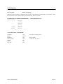
UDL/I Interface
INVOCATION:
SIMULATOR udl/i;
The VGEN interface for the Japanese standard UDL/I Hardware Description Language produces an FWD (Fintronic
Waveform Database) file formatted with events ordered by time.
EXAMPLE OF VECTOR FILE GENERATED:
DECLARATION_SECTION
NUMBER_OF_WAVEFORMS = 7;
RW;
. . .
MODE<3:0>;
END_SECTION
EVENT_SECTION
AT 0 NS
RW := 0;
MODE := 0101;
END 0 NS
AT 23 NS
MODE := 1111;
. . . etc.
VGEN FEATURES SUPPORTED:
Comments
Header
Busformat
Define_Header
Outputs
Bidirects
Sys_clock
Page 32
- YES.
- NO.
- No.
- YES.
- NO.
- NO.
- NO.
Enclose comment strings with /*..*/.
Not a tabular format
Binary only in FWD file.
Replaces DECLARATION_SECTION.
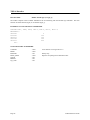
VGEN Interfaces Guide
VALID Tabfile Interface
INVOCATION:
SIMULATOR valid (or valid_prim);
The first VGEN interface for Valid creates a Tabular file containing the pin stimulus. All pins should be declared
with the INPUTS statement in your VGEN source file. The Tabular file contains states that will be deposited to pins
in the design when it is loaded into the simulator environment. Busses may be defined with different radixes using
the BUSFORMAT declarative. The valid_prim option specifies a Valid Primary I/O tabular file format where
expected output states can also be defined and checked by the simulator.
EXAMPLE OF VECTOR FILE GENERATED:
FILE_TYPE = TABULAR_TRACE;
PIN1
PIN2
BUS<7..0>, 16
START_TAB_TRACE
0 / 0,0,ZZ;
100 / 1,0,ZZ;
200 / 0,0,ZZ;
245 / 0,1,ZZ;
255 / 0,1,A7;
etc.
VGEN FEATURES SUPPORTED:
Comments
Header
Busformat
Define_Header
- YES.
- YES.
- YES.
- YES
Outputs
Bidirects
Sys_clock
- YES.
- YES.
- NO.
VGEN Interfaces Guide
Enclose comment strings with {}.
Busses can have radixes individually assigned.
Replaces everything above
START_TAB_TRACE.
With valid_prim only.
With valid_prim only.
Page 33
VALID Scriptfile Interface
INVOCATION:
SIMULATOR valid_s (or valid_sr);
A second VGEN interface for Valid creates a script file containing the pin stimulus. The script file uses the D
(deposit) and S (simulate) commands to apply stimulus and run the simulation. The _sr option is for interfacing a
script file to the newer RapidSim simulator. The script interface allows the user to become more interactive with the
simulator by inserting various commands (such as PAUSE) into the stimulus stream using the COMMENT
statements in VGEN source file. The Tabular file interface , on the other hand, is perhaps a bit easier to follow but
is purely a batch file. The single radix defined with BUSFORMAT applies to all busses. Since there is no real
header (pin list) in this format, the DEFINE_HEADER text string is treated just like a COMMENT string placed at
the top of the script file. All pins should be declared with the INPUTS statement in your VGEN source file.
EXAMPLE OF VECTOR FILE GENERATED:
RADIX 2
D PIN1, 0
D PIN2, 0
D BUS, 00000000
S 100
D PIN1, 1
S 20
D PIN1, 0
S 80
etc.
VGEN FEATURES SUPPORTED:
Comments
Header
Busformat
Define_Header
Outputs
Bidirects
Sys_clock
Page 34
- YES.
- NO.
- YES.
- YES.
- NO.
- NO
- NO.
Can be used to place commands in script file.
Not tabular.
Single radix for all busses.
Text string added to top of file.
VGEN Interfaces Guide
VERILOG Interface
INVOCATION:
SIMULATOR verilog (or verilog_tb);
The VGEN interface for Verilog creates a module called "stimulus". This module should be compiled along with
your circuit module which is assumed to be named "top". Within the stimulus module, local names are created for
the pins and are connected to the signal names of your circuit top module. All pins should be declared with the
INPUTS or SYS_CLOCK declaratives. The SYS_CLOCK declarative can be used for one pin and will cause an
"always" block to be created in the stimulus file which continuously generates the clock with the timing you define.
When defining expected output states on output pins, the verilog_tb option can be used to create a Verilog
Testbench which includes output pin state checking. With verilog_tb, the TITLE command can be used to define
the module (design) name.
EXAMPLE OF VECTOR FILE GENERATED:
module stimulus;
reg vpin1, vpin2;
reg[7:0] vbus;
assign top.\pin1 = vpin1;
assign top.\pin2 = vpin2;
assign top.\bus = vbus;
initial
begin
vbus = 'hZZ;
vpin1 = 0; vpin2 = 0;
#100 vpin1 = 1;
#100 vpin1 = 0;
#80 vbus = 'h5A;
#20 vpin2 = 1;
#100 vpin2 = 0;
etc.
VGEN FEATURES SUPPORTED:
Comments
- YES.
Header
Busformat
Define_Header
- NO.
- YES.
- YES.
Outputs
Bidirects
Sys_clock
- YES.
- YES.
- YES.
VGEN Interfaces Guide
Can be used to insert commands or comments
in stimulus file. First 2 characters must be // for
Verilog to interpret it as a comment.
Only useful for tabular files.
Each bus can have radix individually defined.
Text string (may be multiple lines) replaces
everything above the main "initial" block.
Verilog_tb only.
Verilog_tb only.
Page 35
VHDL Test Bench Interface
INVOCATION:
SIMULATOR vhdl_tb (vhdl_tb_tio);
The first VGEN interface to VHDL (vhdl_tb) creates a test bench file that provides both stimulus to the circuit and,
if expected output states are specified, a check to verify that the expected states match the simulation results. All of
the stimulus and response data is included as part of the test bench file. In the second VHDL interface option
(vhdl_tb_tio), two files are actually created. The first contains the test bench itself with a "read loop" to get data
from an external I/O file. The second is the external I/O file itself which contains all stimulus and response data.
The difference between the two approaches comes out in the VHDL compile time vs. run time. Using the first
interface approach, each time the VGEN source file is modified and compiled to a new test bench, the entire test
bench (with all stimulus) must be re-compiled by the VHDL compiler before simulating. This results in slow
compile time, but fairly fast run time. Using the second interface format, if there are no changes in the pin ordering
or PINTYPE grouping of pins in the VGEN source file, then simply adding or modifying vectors will not require recompilation of the test bench, as only the external I/O file will have changed. Thus, the compile time is minimized
at a slight expense in run time.
In order to provide some additional flexibility, the vhdl_tb (or vhdl_tb_tio) SIMULATOR name can be optionally
followed by one or more of the following parameters (shown with their default values):
LIBRARY="NULL",
USE = "NULL",
UNITS = "ns",
CONFIG = "STRUCTURAL_VIEW",
ARCHITECTURE = "testbench",
CONFIG_FILE = "NULL",
NINE_VALUE = "OFF",
DONT_CARE = "X",
BIT_TYPE = "BIT",
BIT_VECTOR = "BIT_VECTOR",
RESULT_TYPE = 'BIT" ,
RESULT_VECTOR = "BIT_VECTOR",
COMPONENT = "NAME";
Multiple LIBRARY and USE parameters can be specified. The CONFIGURATION declaration is placed in the file
specified by CONFIG_FILE. If this parameter is missing, the declaration is placed at the bottom of the Testbench
file.
The NINE_VALUE parameter tells VGEN to check (or not check) that all states are legal IEEE states. When
specifying output pin states, it is often necessary to mask or "don't care" outputs at various times. The
DONT_CARE parameter specifies what character you will be using in the VGEN source program to indicate this
masked or "don't care" condition. In order to accommodate the variety of TYPEs definable in VHDL, VGEN can
be told to associate an attribute (type) to the pins as they are being defined. This is done by following a pin or bus
name with the attribute value in quotes. The following example illustrates this:
Page 36
VGEN Interfaces Guide
VHDL Test Bench Interface (continued)
INPUTS pin1 "mvl7",
pin2 "mvl7", pin3, pin4, pin5,
adr[15:0],
bus[31:0] "mvl7_vector";
Here we have defined pin1 and pin2 as TYPE mvl7, and bus[31:0] as TYPE mvl7_vector - where mvl7_vector is
assumed to be an unconstrained array. Since pin3 - pin5 had no type specified, they will be given the type specified
in the BIT_TYPE parameter of the parameter list. Likewise, adr[15:0] will be given the type specified in the
BIT_VECTOR parameter.
In order to perform checking of simulation results data against state values specified in the VGEN source file, the
VHDL interfaces create a set of results arrays to which all output pins are connected in the testbench. In addition,
the vhdl_tb_tio interface creates a set of input signal arrays to efficiently read-in data from the external I/O file. The
grouping of pins in these arrays is by PINTYPE command grouping for input pins and strobe timing as defined with
PINTYPE STB commands for output pins. All output pins (and the output version of bidirectional pins) should
have a strobe time defined with this command, and then enabled with the PINTIMING ON command. An example
follows:
PINTYPE NRZ adr, mode @ 15;
PINTYPE STB out, out2, out3 @ 90;
PINTYPE STB bus.o @ 95;
PINTIMING ON out, out2, out3, bus.o;
For the vhdl_tb_tio interface, this will result in an input signal array being created for the adr and mode busses,
which will also be reflected in the organization of data in the external I/O file for these pins. For both interfaces, it
will also result in two arrays being created in the VHDL testbench to contain the expected output states defined in
the VGEN source file. Here, again, we need to be sure that the TYPE of these arrays matches the TYPE of the pins
to which they will be connected.
The type used in the testbench for all signal arrays defaults to being the same type as the pins which comprise the
array - thus one should not mix signal types in the same PINTYPE command. This can be overridden by specifying
a TYPE attribute to be associated with each PINTYPE group. This is done in a manner similar to that shown above
except that only one type is specified for the entire group of pins - since only one TYPE can be defined for the
results array they will comprise. This is done by adding the attribute to the end of the pinlist as shown below:
PINTYPE NRZ adr, mode "mvl7_bus" @ 15;
PINTYPE STB out, out2, out3 "mvl7" @ 90 ;
PINTYPE STB bus.o "mvl7" @ 95;
If a PINTYPE group has no TYPE attribute specified, and the pins which comprise the group have no TYPE
attribute defined, then the group will be defined as having the TYPE specified in the BIT_TYPE parameter for input
arrays, and as in the RESULT_TYPE parameter for results arrays. Note that for busses, the Base Type should be
used, as opposed to the unconstrained array type. This allows us to mix busses and single pins in the same
PINTYPE command.
The TITLE command can be used to specify the name of the design for which the vectors are to be applied.
VGEN Interfaces Guide
Page 37
VHDL Test Bench Interface (continued)
VGEN FEATURES SUPPORTED:
Comments
- YES.
Header
Busformat
Define_Header
Outputs
Bidirects
- NO.
- NO.
- NO.
- YES.
- YES.
Page 38
Can be used to insert commands or comments
in stimulus file. First 2 characters must be -- for
VHDL to interpret it as a comment. Use only
with vhdl_tb interface.
Not a tabular file
Binary only.
VGEN Interfaces Guide
VIEWSIM Interface
INVOCATION:
SIMULATOR viewsim (viewsim1 or viewsim_gen);
The first VGEN interface for ViewLogic actually creates two files used to define stimulus values for pins. The first
file is a command file which defines all of the pins as a single vector (allpins), and then reads in the vector file. The
second file created is the vector file itself. The command file always has the same name as the vector file being
generated, but with a .cmd extension added. The viewsim1 option puts 'ns' with time stamps in the vector file. The
second Viewsim interface generates a Viewsim Generic file format (.gen).
EXAMPLE OF VECTOR FILE GENERATED:
(Command file - ckt.cmd)
vector allpins adr[7:0] dbus[7:0] pin1 pin2 pin3
wfm allpins <ckt.vec
(Vector file - ckt.vec)
@0
=1010101011110000101\B
@100
=1010101011110000001\B
@200
=0000000011110000101\B
@300
=0000000011110000001\B
@400
=1111000010101111101\B
etc.
VGEN FEATURES SUPPORTED:
Comments
- YES.
Header
Busformat
- YES.
- YES.
Define_Header
Outputs
Bidirects
- YES.
- NO.
- NO.
VGEN Interfaces Guide
ViewSim allows comments in the vector file.
The first character in the comment text string
should be '|'.
Since allpins is a single bus, the BUSFORMAT
applies to this bus. If any of the pins take on
non-binary values (i.e. Z or X), the BUSFORMAT
must be set to binary (default). For the .gen
interface, busformat is fully supported.
ViewLogic vector files treat all pins the same.
ViewLogic vector files treat all pins the same.
Page 39
VLSI Technology Interface
INVOCATION:
SIMULATOR vti;
This VGEN interface for VLSI Technology creates a file containing the pin stimulus and optional expected results .
Pins may be declared with the INPUTS, OUTPUTS or BIDIRECT statements in your VGEN source file and the
spacing between pins in the tabular listing can be controlled by putting double commas (,,) in front of pins which
you wish to have a space precede. Busses may be defined with different radixes using the BUSFORMAT
declarative. The UNITS declarative can be set to .1 to get .1NS resolution in the vector file.
EXAMPLE OF VECTOR FILE GENERATED:
@NODES
PIN1
PIN2
BS R2 W8 ;
@DATA
0.0 0
100.0 1
200.0 0
245.0 0
255.0 0
etc.
bs[7] bs[6] bs[5] bs[4] bs[3] bs[2] bs[1] bs[0]
0
0
0
1
1
ZZZZZZZZ
ZZZZZZZZ
ZZZZZZZZ
ZZZZZZZZ
10100111
VGEN FEATURES SUPPORTED:
Comments
Header
Busformat
Define_Header
Outputs
Bidirects
Sys_clock
Page 40
- YES.
- YES.
- YES.
- YES
- YES.
- YES.
- NO.
Precede comment strings with #.
Busses can have radixes individually assigned.
Replaces everything above @DATA.
VGEN Interfaces Guide
WGL Interface
INVOCATION:
SIMULATOR wgl;
This VGEN interface for WGL creates a file containing the pin stimulus and optional expected results . Pins may be
declared with the INPUTS, OUTPUTS or BIDIRECT statements in your VGEN source file. Busses may be
defined with different radixes using the BUSFORMAT declarative. The TITLE statement can be used to name the
waveform block which gets generated. Us the PINTYPE statements (NRZ, RO, RZ, STB) to define the timing to be
placed in the TIMEPLATE section of the WGL file, but do not enable any of the timing with the PINTIMING ON;
statement so the vectors contain only the cycle data.
EXAMPLE OF VECTOR FILE GENERATED:
pattern group_ALL (clk, bus:I, bus:O, pina, pinb)
vector (CIRCUIT_tp) := [ 0 ZZZZZZZZ XXXXXXXX 1 1 ];
vector (CIRCUIT_tp) := [ 1 11110000 XXXXXXXX 1 0 ];
vector (CIRCUIT_tp) := [ 1 00110111 XXXXXXXX 1 0 ];
vector (CIRCUIT_tp) := [ 0 ZZZZZZZZ 110010000 1 1 ];
etc.
VGEN FEATURES SUPPORTED:
Comments
Header
Busformat
Define_Header
Outputs
Bidirects
Sys_clock
VGEN Interfaces Guide
- YES.
- NO.
- NO.
- NO
- YES.
- YES.
- NO.
Precede comment strings with #.
Binary only.
Page 41