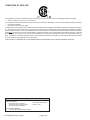
1
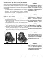
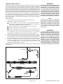
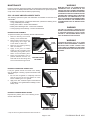
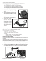
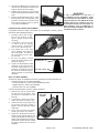
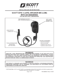
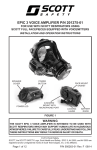
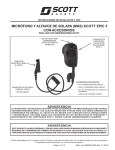
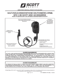
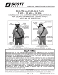
INSTALLATION AND USE INSTRUCTIONS SCOTT EPIC 3 RI voice Amp and EPIC 3 Bluetooth® Lapel Speaker Mic (LSM) communication assembly with Accessories FOR USE WITH SCOTT RESPIRATORS INCORPORATING A SCOTT FACEPIECE WITH DUAL VOICEMITTERS RED EMERGENCY BUTTON (ONLY ON CERTAIN MODELS) EPIC 3 RI VOICE AMP EPIC 3 Bluetooth Lapel speaker Mic (LSM) LOCKING SPRING LEVER RADIO SPECIFIC CONNECTOR Optional Accessories: • Push-to-talk Paddle • Push-to-Talk Ring TYPICAL PORTABLE RADIO TRANSCEIVER (NOT INCLUDED) • Command Throat Mic Kit • Command comms headset WARNING THESE EPIC 3 Bluetooth LAPEL SPEAKER MIC COMMUNICATION ASSEMBLY AND ACCESSORIES ARE INTENDED TO BE USED WITH SCOTT RESPIRATORS WHICH MAY SUPPORT HUMAN LIFE IN HAZARDOUS ATMOSPHERES. FAILURE TO CAREFULLY FOLLOW THESE INSTRUCTIONS AND WARNINGS AND THE INSTRUCTIONS AND WARNINGS CONTAINED IN YOUR SCOTT RESPIRATOR OPERATING AND MAINTENANCE INSTRUCTIONS MAY RESULT IN SERIOUS INJURY OR DEATH. WARNING This product is designed and intended to function properly in reasonable/ordinary firefighting conditions. Like all equipment, the functionality of this product may be compromised by extreme fire conditions © 2015 Scott Safety. SCOTT, the SCOTT SAFETY Logo, Scott Health and Safety, EPIC 3 RI, AV-2000, and AV-3000 are registered and/or unregistered marks of Scott Technologies, Inc. or its affiliates. The Bluetooth trademarks are owned by Bluetooth SIG, Inc. Other trademarks and trade names in this document are those of their respective owners. © 2013 Bluetooth SIG, Inc. Subject to change without prior notice. Page 1 of 24 P/N 595264-01 Rev B 06/15 Conditions of safe use This equipment is listed as intrinsically safe by CSA Group to UL Std. UL-913 for use in the following hazardous locations: • Class I/II, Division I Groups C, D, E, F and G T4 This equipment is listed as intrinsically safe by CSA Group to CSA C22.2 No. 60079-11 for use in the following hazardous locations: • Ex ia IIB T4 (Canada) • Class I Zone 0 AEx ia IIB T4 (USA) To maintain the Intrinsic Safety Listing, inspect equipment regularly per the Regular Operational Inspection procedures in this instruction. Do not tamper with or substitute components in any manner. Use only batteries of the type indicated in the Battery Installation section of these instructions. Do not mix old batteries with unused batteries, or from different manufacturers Open the battery compartments only in an area known to be free of flammable or explosive hazards. Due to the potential for electrostatic discharge, clean with dampened cloth only. Do not use dry cloth to clean the surface. Do not clean and maintenance device in an explosive environment. When connected to a portable Two-way radio, the use of the assembly/radio combination in flammable atmospheres is limited to the most restrictive listing applicable to the two devices This product is Intrinsically safe when used in accordance with control drawing 31003129. Approved Batteries Alkaline Batteries: – Eveready Energizer1 Max E92 – Eveready Energizer Industrial EN92 – Duracell2 Copper Top MN2400 – Duracell Pro-Cell PC2400 – Rayovac3 824 Rechargeable Batteries: – Duracell Rechargeable (NiMH) DC2400 P/N 595264-01 Rev B 06/15 Page 2 of 24 Contents Conditions of safe use..........................................................................................................................2 GENERAL DESCRIPTION..............................................................................................................................5 QUESTIONS OR CONCERNS........................................................................................................................5 BATTERY Use.................................................................................................................................................6 LOW BATTERY ALERT .............................................................................................................................................6 EPIC 3 RI VOICE AMP BATTERY INSTALLATION....................................................................................................7 EPIC 3 Bluetooth LSM BATTERY INSTALLATION..............................................................................................8 PROGRAMMING the EPIC 3 RI VOICE AMP...............................................................................................9 Pairing the EPIC 3 RI VOICE AMP with the EPIC 3 Bluetooth LSM............................................10 INSTALLATION OF THE EPIC 3 RI Voice Amp assembly..................................................................... 11 USE OF RESPIRATOR WITH THE EPIC 3 ri VOICE AMP.........................................................................12 INSPECTION of EPic 3 RI VOICE AMP WITH FACEPIECE.................................................................................12 USE OF EPIC 3 RI VOICE AMP WITH FACEPIECE...............................................................................................12 Connecting EPIC 3 Bluetooth LSM to A PORTABLE TWO-WAY RADIO......................................13 RADIO CABLES AVAILABLE FOR THE EPIC 3 Bluetooth LSM.......................................................................13 USE OF THE EPIC 3 RI COMMUNICATION Assembly WITH A TWO-WAY PORTABLE RADIO.......................................................................................................14 USE OF THE EPIC 3 Bluetooth LSM AS A LAPEL MIC WITH A TWO-WAY PORTABLE RADIO.......15 TERMINATION OF USE................................................................................................................................15 EMERGENCY OPERATION .........................................................................................................................15 ACCESSORIES FOR THE Epic 3 Bluetooth LSM................................................................................16 Connecting the accessories to the epic 3 Bluetooth LSM ............................................................16 PUSH-TO-TALK Ring..............................................................................................................................................17 PUSH-TO-TALK Paddle ........................................................................................................................................17 Command comms Headset..............................................................................................................................18 Command Throat mic Kit.................................................................................................................................19 CLEANING AND INSPECTION ....................................................................................................................20 CLEANING...............................................................................................................................................................20 INSPECTION............................................................................................................................................................20 Maintenance.............................................................................................................................................21 EPIC 3 RI VOICE AMP REPLACEMENT PARTS....................................................................................................21 BATTERY DOOR ASSEMBLY .............................................................................................................................. 21 BATTERY COVER DOOR GASKET ONLY .......................................................................................................... 21 BATTERY cover retaining screw.............................................................................................................. 21 Locking spring lever assembly .............................................................................................................. 22 EPIC 3 Bluetooth LSM REPLACEMENT PARTS..............................................................................................22 BATTERY DOOR REPLACEMENT....................................................................................................................... 22 BATTERY DOOR GASKET REPLACEMENT....................................................................................................... 23 BELT CLIP REPLACEMENT................................................................................................................................. 23 WARRANTY...................................................................................................................................................24 Page 3 of 24 P/N 595264-01 Rev B 06/15 SAFETY LISTINGS FCC COMPLIANCE FCC Compliance Statement (Part 15.19) This device complies with Part 15 of the FCC Rules. Operation is subject to the following two conditions: 1. This device may not cause harmful interference, and 2. This device must accept any interference received, including interference that may cause undesired operation. FCC Warning (Part 15.21) Changes or modifications not expressly approved by the party responsible for compliance could void the user’s authority to operate the equipment. This portable transmitter with its antenna complies with FCC’s RF exposure limits for general population / uncontrolled exposure. The EPIC 3 RI Voice Amplifier / EPIC 3 Bluetooth Lapel Speaker Mic has been assigned FCC ID # QOQWT32AE CLASS B DIGITAL DEVICE Note: This equipment has been tested and found to comply with the limits for a Class B digital device, pursuant to Part 15 of the FCC Rules. These limits are designed to provide reasonable protection against harmful interference in a residential installation. This equipment generates, uses and can radiate radio frequency energy and, if not installed and used in accordance with the instructions, may cause harmful interference to radio communications. However, there is no guarantee that interference will not occur in a particular installation. If this equipment does cause harmful interference to radio or television reception, which can be determined by turning the equipment off and on, the user is encouraged to try to correct the interference by one or more of the following measures: 1. – Reorient or relocate the receiving antenna 2. – Increase the separation between the equipment and receiver. 3. – Connect the equipment into an outlet on a circuit different from that to which the receiver is connected. 4. – Consult the dealer or an experienced radio/TV technician for help. INDUSTRY CANADA COMPLIANCE Industry Canada Statement The term “IC” before the certification / registration number only signifies that the Industry Canada technical specifications were met. Section 14 of RSS-210 The installer of this radio equipment must ensure that the antenna is located or pointed such that it does not emit RF field in excess of Health Canada limits for the general population. Consult Safety Code 6, obtainable from Health Canada’s web site: www. hc-sc.gc.ca/rpb. Operation is subject to the following two conditions: 1. this device may not cause interference, and 2. this device must accept any interference, including interference that may cause undesired operation of the device. IC ID # 5123A-BGTWT32AE La Déclaration de Canada d'industrie L' « IC » de terme avant que la certification/le nombre d'enregistrement signifie seulement que le Canada d'Industrie spécifications techniques ont été rencontrées. Sectionner 14 de RSS-210 Le programme d'installation de cet équipement de radio doit garantir que l'antenne est localisée ou tel est indiqué qu'il n'émet pas le champ de RF dépassant les limites de Canada de Santé pour la population générale. Consulter le Code de Sécurité 6, procurable du site Web de Canada de Santé : www.hc-sc.gc.ca/rpb. L'opération est assujetti au suivre deux conditions : 1) cet appareil ne peut pas causer l'intervention, et 2) cet appareil doit accepter de l'intervention, y compris l'intervention qui peut causer l'opération non désirée de l'appareil. IC ID # 5123A-BGTWT32AE P/N 595264-01 Rev B 06/15 Page 4 of 24 GENERAL DESCRIPTION The EPIC 3 RI Voice Amplifier and EPIC 3 Bluetooth Lapel Speaker Mic (lsm) provide facepiece voice amplification and wireless voice communications when connected to a portable two-way radio (supplied by the user). The EPIC 3 RI (Radio Interface) communication assemblies are intended for installation only on approved SCOTT respirators equipped with SCOTT full facepieces with dual voicemitters. Training is required before use. These assemblies are not intended for use under water or for any purpose not specifically authorized by the organized respiratory program that applies to the specific user. The EPIC 3 RI communication system consists of: • EPIC 3 RI Voice Amp - Facepiece mounted, battery powered voice amplifier with integrated Bluetooth wireless technology; • EPIC 3 Bluetooth LSM - Bluetooth wireless technology equipped transmitter fitted with a specific two-way radio communication cable and connector; and • Two-way Portable radio - Compatible two-way portable radio (supplied by user). The voice amplifier device attaches to the voicemitter bracket mounted on either side of an approved Scott Safety full facepiece. Accessory mounting brackets are available for compatible SCOTT respirator facepieces not already equipped with voicemitter brackets. Both the RI Voice Amp and the Bluetooth LSM assemblies require three (3) approved AAA batteries installed. The complete system requires (3) AAA Batteries each for a total of six (6) AAA batteries. The RI Voice Amp must be paired with the Bluetooth LSM to establish the wireless link. When connected to a Bluetooth LSM with portable two-way radio, pressing the large push-to-talk button on the Bluetooth LSM will activate the push-to-talk function of the two-way portable radio. The RI Voice Amp will transmit the amplified voice communications over the portable two-way radio. In the event that the RI Voice Amp is lost or damaged during use, the Bluetooth LSM can continue to function as a remote speaker mic with the portable two-way radio after the Bluetooth pairing link with the RI VOICE AMP has been disconnected. Refer to the EMERGENCY OPERATION section of this instruction for details. Certain Bluetooth LSM models are equipped with a RED Emergency Button to operate the corresponding emergency alert feature on compatible portable radios. Refer to the user manual for your portable two-way radio for details of use. If the RED Emergency Button is not installed on your unit, that feature is not available. LED’s on the RI Voice Amp assembly and the Bluetooth LSM assembly light to indicate operation. To conserve battery life, the RI Voice Amp assembly features an automatic power OFF feature that shuts off the power after twenty (20) minutes of inactivity. When the Bluetooth LSM assembly is connected to a portable two-way radio, the use of the assembly/radio combination in flammable atmospheres is limited to the most restrictive hazardous location listing applicable to the two devices. If the Bluetooth LSM assembly is connected to a non-intrinsically safe radio, the combination may not be used in flammable or explosive atmospheres. The Bluetooth LSM assembly is available in a variety of cord/connector configurations to fit popular brands and models of portable two-way radios. Each configuration has a unique part number representing the radio specific connector used to attach it to the portable two-way radio for which it was designed. Do not attempt to attach an Bluetooth LSM assembly to a portable two-way radio for which it was not designed. Optional Push-To-Talk Paddle and Push-To-Talk Ring accessories can be actuated when worn under an encapsulating protective garment. Also available are a command comms headset with microphone and a throat mic KIT that includes a throat mic, ear buds and push-to-talk ring. If these accessories are being used with a two-way portable radio in a fire fighting application, the two-way portable radio, all cables, and the accessory must be contained within the fire fighter’s turnout gear for protection from heat and flame. QUESTIONS OR CONCERNS If you have any questions or concerns regarding use of this equipment, contact your authorized SCOTT distributor, or contact SCOTT at 1-800-247-7257 (or 704-291-8300 outside the continental United States). Page 5 of 24 WARNING Training IS REQUIRED BEFORE USE, ESPECIALLY IN AN EMERGENCY SITUATION. USE OF THIS EQUIPMENT WITHOUT PROPER TRAINING COULD LEAD TO SERIOUS INJURY OR DEATH. WARNING THE USE OF AN INTRINSICALLY SAFE DEVICE IN AN ATMOSPHERE FOR WHICH IT IS NOT LISTED OR THE USE OF A NON-INTRINSICALLY SAFE DEVICE IN A FLAMMABLE OR EXPLOSIVE AT M O S P H E R E M AY L E A D TO F I R E O R EXPLOSION RESULTING IN SERIOUS INJURY OR DEATH. WARNING When the EPIC 3 Bluetooth Lapel Speaker Mic assembly is connected to a portable Two-way radio, the use of the assembly/radio combination in flammable OR EXPLOSIVE atmospheres is limited to the most restrictive INTRINSIC SAFETY listing applicable to the two devices. IF THE EPIC 3 Bluetooth Lapel Speaker Mic assembly IS CONNECTED TO A NONINTRINSICALLY SAFE RADIO, THE COMBINATION MUST NOT BE USED IN FLAMMABLE OR EXPLOSIVE ATMOSPHERES. THE USE OF A NON-INTRINSICALLY SAFE DEVICE IN A FLAMMABLE OR EXPLOSIVE AT M O S P H E R E M AY L E A D TO F I R E O R EXPLOSION RESULTING IN SERIOUS INJURY OR DEATH. CAUTION Each configuration of the EPIC 3 Bluetooth LSM assembly is designed to fit a specific brand and model portable two-way radio. Do not attempt to connect the EPIC 3 Bluetooth Lapel Speaker Mic assembly to a different brand or model portable two-way radio. it may cause damage to the Bluetooth Lapel Speaker Mic, the radio, or both. WARNING DO NOT USE accessories IN APPLICATIONS which MAY EXPOSE IT TO HIGH HEAT OR FLAME. If used in a fire fighting application, All accessories and cables must be contained within the fire fighter’s turnout gear for protection from heat and flame. EXPOSURE TO HIGH HEAT OR FLAME MAY CAUSE THE accessory TO MELT OR BURN WHICH COULD RESULT IN SERIOUS Injury or death TO THE USER. P/N 595264-01 Rev B 06/15 Battery cover IN BACK EMERGENCY BUTTON Speaker Locking SPRING LEVER Battery cover MICROPHONE LED INDICATOR LIGHT PUSH-TO TALK BUTTON Amplifier SPEAKER LED INDICATOR light Power/ function button EPIC 3 RI VOICE AMP Accessory CONNECTION With cap RADIO CABLE EPIC 3 Bluetooth LSM WARNING BATTERY Use Both the RI Voice Amp and Bluetooth LSM assemblies require battery power to operate. This comes from three (3) approved AAA batteries installed. The complete system requires three (3) AAA Batteries for each of the two units for a total of six (6) AAA batteries. NOTE THE RI VOICE AMP and Bluetooth LSM are SHIPPED FROM THE FACTORY WITH ALKALINE BATTERIES INSTALLED AND A BATTERY ISOLATOR label TO PREVENT BATTERY DRAIN. REMOVE THE BATTERY ISOLATOR label BEFORE USE. To remove battery isolator: • RI Voice Amp: Open the battery door to pull isolator label from battery compartment. Close and secure the battery door before use • Bluetooth LSM: Pull isolator label from battery compartment. LOW BATTERY ALERT Total battery life is dependent on conditions of use. WHEN THE LOW BATTERY INDICATION APPEARS (FLASHING RED only OR FLASHING ALTERNATELY BETWEEN RED AND GREEN AND ACCOMPANIED BY A CHIRP) CHANGE THE BATTERIES IMMEDIATELY. FAILURE TO CHANGE LOW BATTERIES IN A TIMELY MANNER MAY RESULT IN FAILURE OF THE EQUIPMENT IN AN EMERGENCY SITUATION WHICH COULD RESULT IN SERIOUS INJURY OR DEATH. WARNING CHANGE BATTERIES ONLY IN AN AREA KNOWN TO BE NONFLAMMABLE. CHANGING BATTERIES MAY CAUSE A SPARK THAT COULD IGNITE A FLAMMABLE OR EXPLOSIVE ATMOSPHERE RESULTING IN SERIOUS INJURY OR DEATH. The RI Voice Amp LED will flash RED and chirp at 20 second intervals to indicate that the batteries are low. After 60 minutes the blink rate will increase to 10 second intervals and the unit will chirp at a slightly louder volume . • If paired with the Bluetooth LSM, the LED will flash alternating RED and GREEN. WARNING • If NOT paired with the Bluetooth LSM, the LED will flash RED THE BATTERIES MUST BE PROPERLY ORIENTED only. WHEN THE LED IS FLASHING, AND IS EMITTING A CHIRP, CHANGE THE BAT- IN THE BATTERY HOLDER FOR THE EQUIPMENT TO OPERATE. IMPROPER INSTALLATION OF TERIES IMMEDIATELY. The Bluetooth LSM will flash RED to indicate that the batteries are low when approximately one hour of operating time remains. • If paired with the RI Voice AMP, the LED will flash alternating RED and GREEN. • If NOT paired the RI Voice AMP, the LED will flash RED only. WHEN THE LED IS FLASHING CHANGE THE BATTERIES IMMEDIATELY. P/N 595264-01 Rev B 06/15 Page 6 of 24 THE BATTERIES WILL RESULT IN FAILURE OF THE EQUIPMENT WHICH COULD RESULT IN SERIOUS INJURY OR DEATH EPIC 3 RI VOICE AMP BATTERY INSTALLATION The RI Voice Amp Assembly requires three AAA batteries installed in the microphone/ speaker unit. Use only three fresh batteries from the following lists. Alkaline Batteries: Rechargeable Batteries: – Eveready Energizer1 Max E92 – Duracell Rechargeable (NiMH) DC2400 – Eveready Energizer Industrial EN92 – Duracell2 Copper Top MN2400 – Duracell Pro-Cell PC2400 – Rayovac3 824 WARNING CHANGE BATTERIES ONLY IN AN AREA KNOWN TO BE NONFLAMMABLE. CHANGING BATTERIES MAY CAUSE A SPARK THAT COULD IGNITE A FLAMMABLE OR EXPLOSIVE ATMOSPHERE RESULTING IN SERIOUS INJURY OR DEATH. Do not mix battery types, old and new batteries, or batteries from different manufacturers. When using rechargeable batteries, verify that they are fully charged before WARNING use. Use of any other batteries except those listed will void the intrinsic safety listing THE USE OF BATTERIES OTHER THAN THOSE of the RI Voice Amp Assembly. The area must be known to be nonflammable and LISTED in this instruction OR REPLACING safe before opening the battery door. BATTERIES IN AN AREA WHICH IS NOT KNOWN NOTE THE RI VOICE AMP IS SHIPPED FROM THE FACTORY WITH ALKALINE BATTERIES INSTALLED AND A BATTERY ISOLATOR label TO PREVENT BATTERY DRAIN. open the battery door and REMOVE THE BATTERY ISOLATOR label BEFORE USE. (refer to Battery use section of this instruction.) TO BE FREE OF FLAMMABLE GASES AND VAPORS MAY CAUSE A FIRE OR EXPLOSION AND MAY LEAD TO INJURY OR DEATH. WARNING Install batteries as follows: THE BATTERIES MUST BE PROPERLY ORIENTED 1. Use a #1 Phillips screwdriver to open the battery door. Turn the battery WHEN INSTALLED FOR THE EQUIPMENT TO door screw counterclockwise. Lift open the hinged door. OPERATE. IMPROPER INSTALLATION OF THE 2. Inspect the contacts for corrosion or damage. If any discrepancy is found, do not use the unit. Return to an authorized SCOTT repair center for service. 3. Insert the batteries into the battery compartment. Be sure to check orientation of + and - polarity of batteries as marked on the outside of the battery compartment. 4. Verify that the seal around the battery door is clean and undamaged. POLARITY 5. Close the battery door. MARKED ON 6. Turn the screw clockwise to tighten Housing until snug. Do not over tighten. 7. Press the POWER Button for one (1) second to turn the RI VOICE AMP ON. The GREEN POWER LED will illuminate indicating the amplifier is ON and the unit will sound a sequence of ASCENDING tones based on the programming of the unit (4 tones for Open Bracket and 5 tones for Closed Bracket). If the LED does not illuminate, verify that ALL the batteries are fresh AND that they are properly installed. The unit may emit a high pitched tone (feedback) as the Auto Gain function sets the optimum output. BATTERIES WILL RESULT IN FAILURE OF THE EQUIPMENT WHICH COULD RESULT IN SERIOUS INJURY OR DEATH. CAUTION TIGHTEN THE SCREW ONLY UNTIL IT IS SNUG. DO NOT OVERTIGHTEN. If the LED is flashing RED, the batteries are low and must be changed before use of the RI Voice Amp. 8. To verify proper operation, speak into the microphone port in the D-shaped mount. The voice should be heard amplified coming from the speaker. 9. To turn OFF the RI VOICE AMP, press and HOLD the Power Button for three (3) seconds. The unit will sound a sequence of two (2) DESCENDING tones to indicate the unit is OFF and the LED will go OFF. Energizer is a registered trademark of Eveready Battery Company, Inc., St. Louis, MO. Duracell is a registered trademark of The Procter & Gamble Company, Cincinnati, OH. 3 Rayovac is a registered trademark of Spectrum Brands, Madison WI. 1 2 Page 7 of 24 P/N 595264-01 Rev B 06/15 EPIC 3 Bluetooth LSM BATTERY INSTALLATION The Bluetooth LSM Assembly requires three AAA batteries installed in the battery holder. Use only three fresh batteries from the following lists. Alkaline Batteries: Rechargeable Batteries: – Eveready Energizer1 Max E92 – Duracell Rechargeable (NiMH) DC2400 – Eveready Energizer Industrial EN92 – Duracell2 Copper Top MN2400 – Duracell Pro-Cell PC2400 – Rayovac3 824 Do not mix battery types, old and new batteries, or batteries from different manufacturers. When using rechargeable batteries, verify that they are fully charged before use. Use of any other batteries except those listed will void the intrinsic safety listing. The area must be known to be nonflammable and safe before opening the battery door. NOTE THE Bluetooth LSM IS SHIPPED FROM THE FACTORY WITH ALKALINE BATTERIES INSTALLED AND A BATTERY ISOLATOR LABEL TO PREVENT BATTERY DRAIN. REMOVE THE BATTERY ISOLATOR LABEL BEFORE USE. (refer to Battery use section of this instruction.) WARNING CHANGE BATTERIES ONLY IN AN AREA KNOWN TO BE NONFLAMMABLE. CHANGING BATTERIES MAY CAUSE A SPARK THAT COULD IGNITE A FLAMMABLE OR EXPLOSIVE ATMOSPHERE RESULTING IN SERIOUS INJURY OR DEATH. WARNING THE USE OF BATTERIES OTHER THAN THOSE LISTED in this instruction OR REPLACING BATTERIES IN AN AREA WHICH IS NOT KNOWN TO BE FREE OF FLAMMABLE GASES AND VAPORS MAY CAUSE A FIRE OR EXPLOSION AND MAY LEAD TO INJURY OR DEATH. 1. Open Battery Door, using a Phillips screwdriver, turn the two (2) battery door screws counterclockwise until the door is released. 2. Inspect assembly for damage. Check contacts inside the Battery Compartment for dirt, corrosion, or damage. Clean as needed. If any damage beyond the scope of this instruction is found, do not use unit. Return to authorized SCOTT repair center for service. WARNING POLARITY MARKED IN BATTERY COMPARTMENT THE BATTERIES MUST BE PROPERLY ORIENTED WHEN INSTALLED FOR THE EQUIPMENT TO OPERATE. IMPROPER INSTALLATION OF THE BATTERIES WILL RESULT IN FAILURE OF THE EQUIPMENT WHICH COULD RESULT IN SERIOUS INJURY OR DEATH. 3. Place batteries in battery compartment. Check orientation of + and polarity of batteries as marked in the bottom of battery compartment. 4. Verify that the seal around the inside of the battery compartment is clean and undamaged. If the gasket or battery door is damaged, refer to the REPLACEMENT OF Bluetooth LSM BATTERY DOOR section of CLEANING AND MAINTENANCE in this instruction for replacement details. 5. Close the battery door. Using a Phillips screwdriver, tighten the two battery door screws until they are snug. DO NOT OVERTIGHTEN. NOTE CONNECT THE Bluetooth LSM TO A TWO-WAY PORTABLE RADIO TO CONFIRM THAT THE Bluetooth LSM IS OPERATING PROPERLY. 6. Attach Bluetooth LSM assembly to portable two-way radio and turn CAUTION radio ON according to user instructions provided with portable two-way TIGHTEN THE SCREWS ONLY UNTIL THEY ARE radio. The LED on the Bluetooth LSM will light GREEN when radio SNUG. DO NOT OVERTIGHTEN. has been turned ON. If the LED does not illuminate, repeat steps 1–6. Verify that ALL the batteries are fresh AND that they are properly installed. If it still does not illuminate, remove from service and tag for repair or replacement. 7. Proceed to the PAIRING THE EPIC 3 RI VOICE AMP WITH THE EPIC CAUTION 3 Bluetooth LSM section of this instruction. THE EPIC 3 Bluetooth lapel speaker mic MUST BE CONNECTED TO A TWO-WAY PORTABLE RADIO TO CONFIRM THAT IT IS OPERATING PROPERLY. P/N 595264-01 Rev B 06/15 Page 8 of 24 PROGRAMMING the EPIC 3 RI VOICE AMP The RI VOICE AMP communications assembly is designed for use with a SCOTT Full Facepiece equipped with voicemitters and a compatible SCOTT AUDIO ACCESSORY BRACKET. The AUDIO ACCESSORY BRACKETS are available as either OPEN or CLOSED front depending on the approved facepiece being used. In addition, the RI Voice Amp may be powered by approved batteries that are either Alkaline or Rechargeable NiMH. For proper performance, the RI VOICE AMP must be programmed for the type of ACCESSORY BRACKET and Batteries being used. Each RI VOICE AMP is preprogrammed at the factory for use with Alkaline batteries and either an OPEN accessory bracket or CLOSED accessory bracket configuration. Ri voice amps programmed for open brackets will emit 4 tones upon startup and amps programmed for closed bracket will emit 5 tones. RI VOICE AMP assembly P/N 201276-01 PREPROGRAMMED FOR AN OPEN BRACKET RI VOICE AMP assembly P/N 201276-02 PREPROGRAMMED FOR A CLOSED BRACKET If the RI VOICE AMP is to be used with a bracket style different from the original factory setting or with Rechargeable NiMH Batteries, the unit must be reprogrammed for proper performance with the correct configuration. To change the programming of the RI VOICE AMP, proceed as follows: 1. Use a #1 Phillips screwdriver to open the battery door. Turn the battery door screw counterclockwise. Lift open the hinged door. 2. While holding down the POWER Button, close the battery door. Continue holding the POWER Button until the LED lights ORANGE. 3. Once the power button is released, the RI VOICE AMP will emit a long audible tone to indicate that the unit is now in Programming Mode. The LED on the amplifier will then light according to the current setting. POWER LED SOLID GREEN FLASHING GREEN SOLID ORANGE FLASHING ORANGE WARNING THE EPIC 3 RI Voice Amp COMMUNICATIONS Assembly MUST BE PROGRAMMED FOR THE TYPE OF BATTERIES USED AS WELL AS FOR THE TYPE OF AUDIO ACCESSORY BRACKET BEING USED. FAILURE TO VERIFY THAT THE UNIT IS PROPERLY PROGRAMMED MAY RESULT IN REDUCED PERFORMANCE WHICH COULD LEAD TO SERIOUS INJURY OR DEATH. BRACKETBATTERY TONE One (1) TONE Two (2) TONES Three (3) TONES Four (4) TONES TYPE OPEN CLOSED OPEN CLOSED WARNING WHEN THE LOW BATTERY INDICATION APPEARS (FLASHING RED only OR FLASHING ALTERNATELY BETWEEN RED AND GREEN AND ACCOMPANIED BY A CHIRP) CHANGE THE BATTERIES IMMEDIATELY. FAILURE TO CHANGE LOW BATTERIES IN A TIMELY MANNER MAY RESULT IN FAILURE OF THE EQUIPMENT IN AN EMERGENCY SITUATION WHICH COULD RESULT IN SERIOUS INJURY OR DEATH. TYPE Alkaline Alkaline NiMH NiMH NOTE If no activity is detected for thirty (30) seconds, the unit will time out and turn itself OFF. 4. To toggle between settings, Press and hold the POWER Button for one (1) full second. Each configuration will appear in turn. NOTE If POWER Button is held less than one (1) full second while toggling between settings, The led will turn red, The AMP will emit a descending tone and then will turn itself OFF. Steps 1–4 will need to be repeated. 5. When you reach the configuration you need, SAVE the setting by pressing and holding the POWER Button for three (3) seconds. The POWER LED will glow GREEN and the unit will emit an ascending tone to indicate a successful SAVE. Once saved, release the POWER Button and the unit will turn OFF. If the LED light turns RED the programming was not saved. Repeat steps 1–5 until you have a successful SAVE. 6. Turn the battery door screw clockwise to tighten until snug. Do not over tighten. 7. Install the RI VOICE AMP on the facepiece to be used and perform the REGULAR OPERATIONAL INSPECTION as described in this instruction. If any operational problems are found that may relate to the programming, remove the RI Voice Amp from the facepiece and repeat the programming as instructed above to verify that the proper changes are saved. If the programming is verified and the unit still does not operate properly, remove the unit from service and tag for repair. Page 9 of 24 P/N 595264-01 Rev B 06/15 Pairing the EPIC 3 RI VOICE AMP with the EPIC 3 Bluetooth LSM The RI Voice Amp utilizes integrated Bluetooth®wireless technology to communicate with the Bluetooth LSM. Linking the units is referred to as “pairing”. After the initial “pairing” procedure, RI Voice Amp and Bluetooth LSM will search for the same unit to connect with each time either unit is powered on. To pair the RI Voice Amp assembly with the Bluetooth LSM assembly, proceed as follows: 1. Verify that both the RI Voice Amp assembly and the Bluetooth LSM assembly have fresh batteries. 2. Attach the Bluetooth LSM assembly to the portable two-way radio. If any accessory is connected to the Bluetooth LSM assembly, remove it before proceeding. 3. Turn ON the RI Voice AMP unit by pressing and holding down the power button approximately three to four (3–4) seconds until the LED turns from GREEN to ORANGE. Proceed to the next step immediately. If no activity is detected within thirty (30) seconds, the RI AMP will time out and turn itself off. 4. Press and hold the Push-To-Talk button on the Bluetooth LSM. While holding down the Push-To-Talk button, turn ON the two-way portable radio according to manufacturer instructions. Release PUSH-TO-TALK button when the LED turns from GREEN to ORANGE. 5. Place the RI Voice Amp and Bluetooth LSM within close proximity, no more than 12” apart. NOTE WARNING IF THE UNITS WILL NOT PAIR or connect AS DESCRIBED IN THESE INSTRUCTIONS, REMOVE THEM FROM SERVICE AND TAG FOR REPAIR OR REPLACEMENT. USE OF EQUIPMENT THAT IS NOT OPERATING PROPERLY COULD LEAD TO CIRCUMSTANCE THAT MAY RESULT IN SERIOUS INJURY OR DEATH. The Bluetooth LSM will Pair with the first RI Voice Amp that it locates. To avoid a link to a unit other than the intended RI Voice Amp, avoid pairing within 6 feet of other units. 6. The LED on both units will begin to flash ORANGE. 7. Once a link is established both LED’s will flash twice and then change to solid GREEN. Upon establishing link, the unit will also emit an audible tone. If no link was established within thirty (30) seconds the LED on RI VOICE AMP will turn a solid ORANGE and the LED on the Bluetooth LSM will turn off. If the units do not pair, repeat steps 1–6. If they still do not pair, remove them from service and tag for repair or replacement. 8. The ri VOICE AMP and the Bluetooth LSM will remain paired to the same unit until they are paired with other units. Changing batteries will not affect the paired units. 9. To pair a RI VOICE AMP with a different Bluetooth LSM, repeat the procedure above. NOTE ONCE A Bluetooth LSM HAS BEEN Paired WITH An RI voice AMP (GREEN LED), THE Bluetooth LSM WILL NOT OPERATE AS A LAPEL MIC WITH THE PORTABLE TWO-WAY RADIO UNTIL THE LINK HAS BEEN BROKEN. SEE THE EMERGENCY OPERATION SECTION OF THIS INSTRUCTION FOR DETAILS. aLL PREVIOUS Pairing BETWEEN THE RI VOICE AMP AND THE Bluetooth LSM will be lost if: • the power button on the amp is held down for 3-4 seconds or • the Push-to-talk button on the Bluetooth LSM IS PRESSED WHILE TURNING ON THE RADIO. P/N 595264-01 Rev B 06/15 Page 10 of 24 WARNING Training IS REQUIRED BEFORE USE, ESPECIALLY IN AN EMERGENCY SITUATION. USE OF THIS EQUIPMENT WITHOUT PROPER TRAINING COULD LEAD TO SERIOUS INJURY OR DEATH. INSTALLATION OF THE EPIC 3 RI Voice Amp assembly The RI Voice Amp facepiece assembly may be used with any approved SCOTT respirator which includes a full facepiece equipped with dual voicemitters. Installation includes pairing the Facepiece assembly with the Bluetooth LSM assembly, mounting the facepiece assembly on the facepiece, connecting the Bluetooth LSM assembly to a portable two-way radio via the cord and radio connector, securing the Bluetooth LSM to the protective gear, and placing the portable two-way radio on the user’s person. 1. See Audio Accessory Mounting Bracket Installation Instructions (P/N 595107-01 closed bracket; P/N 595287-01 open bracket) for details of attaching the mounting bracket to your SCOTT full facepiece. Verify that bracket is properly mounted for your SCOTT full facepiece before proceeding. On the AV-2000 facepiece, pay special attention to the free movement of the head harness tabs. WARNING THE COMMUNICATIONS Accessory MUST BE PROPERLY INSTALLED SO THAT IT DOES NOT INTERFERE WITH THE OPERATION OR FIT OF THE FACEPIECE IN ANY WAY. IMPROPER INSTALLATION MAY RESULT IN A POOR FACEPIECE TO FACE FIT WHICH MAY EXPOSE THE USER OF THE RESPIRATOR TO THE HAZARDOUS ATMOSPHERE LEADING TO SERIOUS INJURY OR DEATH. NOTE THE RI voice AMP Assembly WILL ONLY FIT ON AUDIO ACCESSORY BRACKET WARNING P/N 200264-XX and P/N 200265-XX OR SERVICE KIT BRACKETS P/N 200715-XX, ON THE AV-2000 FULL FACEPIECE, VERIFY THAT P/N 200716-XX, AND P/N 201210-XX. THE HEAD HARNESS TABS ROTATE FREELY 2. The body of the RI Voice Amp facepiece assembly is keyed so that it fits in the mounting bracket only one way. Attach the facepiece assembly to the mounting bracket as follows: a) Hold the RI Voice Amp with the battery compartment door facing the top right harness tab. b) Align the D-shaped mount on the rear of the amplifier with the opening in the center of the audio accessory bracket and press in. c) While pressing the Accessory in towards the side of the facepiece rotate the Accessory 1/4 turn counter clockwise. The lock will make two (2) “clicks”. The second “click” will lock the accessory into place. d) To verify that the RI Voice Amp is properly locked, try to rotate the accessory clockwise WITHOUT lifting up on the Locking Lever. If the Accessory will not turn, it is properly locked. e) A screw is provided in the Locking Lever to prevent accidental removal when mounted on an open bracket. Use a Phillips screwdriver to tighten the screw snug. Do not over tighten. AFTER INSTALLATION OF THE MOUNTING BRACKET. IF THE TABS FAIL TO ROTATE FREELY, IT MAY RESULT IN A POOR FACEPIECE TO FACE FIT AND MAY EXPOSE THE USER OF THE RESPIRATOR TO THE HAZARDOUS ATMOSPHERES RESULTING IN SERIOUS INJURY OR DEATH. CAUTION VERIFY THAT THE PROPER AUDIO ACCESSORY BRACKET IS INSTALLED ON THE FACEPIECE. THE EPIC 3 RI voice amp Assembly WILL ONLY FIT ON AUDIO ACCESSORY BRACKET P/N 200264-XX and P/N 200265-xx OR SERVICE KIT BRACKETS P/N 200715-XX, P/N 200716-XX, AND P/N 201210-XX. CAUTION TURN THE FACEPIECE ASSEMBLY CAREFULLY TO INSTALL. DO NOT FORCE. THE EPIC 3 RI VOICE AMP SHOULD FIT SNUGLY TO THE FACEPIECE. IF THE FACEPIECE ASSEMBLY WILL NOT TURN, CHECK THE ALIGNMENT AND CONFIRM THAT THE AUDIO ACCESSORY BRACKET IS PROPERLY INSTALLED. ROTATE COUNTER CLOCKWISE TO LOCK LOCKED POSITION INSTALLATION OF THE EPIC 3 RI Voice Amp Page 11 of 24 WARNING WHEN INSTALLING THE COMMUNICATIONS ACCESSORY, VERIFY THAT THE LATCH IS FULLY ENGAGED AFTER THE SECOND “CLICK.” USE THE LOCKING LEVER SCREW TO SECURE. FAILURE TO VERIFY PROPER INSTALLATION MAY RESULT IN LOSS OF THE COMMUNICATIONS ACCESSORY WHICH COULD LEAD TO SERIOUS INJURY OR DEATH. P/N 595264-01 Rev B 06/15 USE OF RESPIRATOR WITH THE EPIC 3 ri VOICE AMP INSPECTION of EPic 3 RI VOICE AMP WITH FACEPIECE 1. Before donning the facepiece, inspect the RI Voice AMP housing for damage such as cracks, chips, discoloration, corrosion, missing or loose parts, or burned or melted components. 2. Inspect the Mounting Bracket for damaged, missing, or loose components. Verify that the Mounting Bracket is firmly attached to the facepiece according to the Mounting Bracket Instructions. 3. Verify the RI Voice AMP is properly installed on Mounting Bracket. 4. Verify operation of the RI Voice AMP. Turn ON unit by pressing and holding down power button for approximately one (1) full second. Release POWER button when the LED turns from GREEN to ORANGE. Note WARNING IF ANY COMPONENT OF THE EPIC 3 RI COMMUNICATIONS Assembly DOES NOT PERFORM AS DESCRIBED IN THESE INSTRUCTIONS OR IF ANY DAMAGE IS FOUND DURING INSPECTION, REMOVE THE UNIT FROM SERVICE AND TAG FOR REPAIR OR REPLACEMENT. USE OF DAMAGED OR MALFUNCTIONING EQUIPMENT MAY RESULT IN SERIOUS INJURY OR DEATH. If the LED fails to illuminate, OR if UNIT IS INDICATING A LOW BATTERY (FLASHING RED OR ALTERNATING RED/GREEN AND EMITTING A CHIRP) , DO WARNING NOT USE the ri VOICE AMPLIFIER. Remove the unit from service. Refer DO NOT USE THE EPIC 3 RI COMMUNICATIONS to the BATTERY INSTALLATION section of this instruction. USE OF EPIC 3 RI VOICE AMP WITH FACEPIECE 1. Don the facepiece according to the instructions provided with the complete respirator. Always draw the facepiece firmly to the face to assure a proper seal. If you cannot achieve a good facepiece fit with the RI Voice AMP installed, do not use the respirator. 2. Because the RI Voice AMP is physically mounted on the respirator facepiece, use care to prevent snags or impacts on the amplifier from dislodging the respirator facepiece and exposing the respirator user to the hazardous atmosphere. 3. Use the RI Voice AMP with a normal speaking voice. Yelling or speaking too loudly may result in unintelligible voice transmission. 4. After approximately twenty (20) minutes of inactivity (no voice input) the RI VOICE AMP will automatically turn itself OFF. To reactivate, press the POWER Button. NOTE Always draw the facepiece firmly to the face to assure a proper seal. If you cannot achieve a good facepiece fit with the RI Voice AMP installed, do not use the respirator. NOTE BE CERTAIN THAT THE RI Voice Amp facepiece assembly DOES NOT INTERFERE WITH ANY PROTECTIVE HEAD GEAR. NOTE DIRT OR FOREIGN MATTER IN THE CONNECTOR CAN INTERFERE WITH THE CONNECTION AND/OR PREVENT POSITIVE LOCKING OF THE CONNECTOR. CONNECTORS MUST BE KEPT CLEAN OF DIRT. SEE CLEANING AND MAINTENANCE SECTION OF THIS INSTRUCTION. LED INDICATOR LIGHT P/N 595264-01 Rev B 06/15 POWER BUTTON Page 12 of 24 Assembly WITH A BROKEN OR DAMAGED CASE OR EXPOSED WIRING. IN A FLAMMABLE OR EXPLOSIVE ATMOSPHERE SUCH DAMAGE MAY RESULT IN A FIRE OR EXPLOSION AND CAUSE SERIOUS INJURY OR DEATH. WARNING FAILURE TO DON FACEPIECE TIGHTLY AS INSTRUCTED MAY EXPOSE THE USER TO THE HAZARDOUS ATMOSPHERE THE RESPIRATOR IS DESIGNED TO PROTECT AGAINST AND RESULT IN SERIOUS INJURY OR DEATH. WARNING DO NOT USE THE RESPIRATOR IF LEAKAGE OF AIR INTO THE FACEPIECE IS DETECTED DURING SEAL CHECK. SEE RESPIRATOR INSTRUCTIONS IF LEAKAGE IS PRESENT. USE OF AN IMPROPERLY FITTED FACEPIECE MAY EXPOSE THE USER TO THE HAZARDOUS ATMOSPHERE WHICH MAY RESULT IN SERIOUS INJURY OR DEATH. WARNING WHEN THE LOW BATTERY INDICATION APPEARS (FLASHING RED only OR FLASHING ALTERNATELY BETWEEN RED AND GREEN AND ACCOMPANIED BY A CHIRP) CHANGE THE BATTERIES IMMEDIATELY. FAILURE TO CHANGE LOW BATTERIES IN A TIMELY MANNER MAY RESULT IN FAILURE OF THE EQUIPMENT IN AN EMERGENCY SITUATION WHICH COULD RESULT IN SERIOUS INJURY OR DEATH. Connecting EPIC 3 Bluetooth LSM to A PORTABLE TWO-WAY RADIO The following instructions apply to the use of a Bluetooth LSM assembly with an approved portable two-way radio. All cords must be positioned such that they do not interfere with the function of the respirator or present a safety hazard to the user. 1. Attach the radio connector from the Bluetooth LSM to the portable two-way radio according to the instructions provided with the two-way portable radio. 2. The user must place the radio on his person so that the radio is protected and securely attached. There must not be excessive slack in the cord from the push-to-talk button to the radio which could present a hazard of snagging. 3. Position Bluetooth LSM assembly where it will be readily accessible. Secure the cord to the two-way portable radio. 4. If the Bluetooth LSM assembly is being used with a two-way portable radio in a fire fighting application, two-way portable radio and radio cable must be contained within the fire fighter’s turnout gear for protection from heat and flame. WARNING DO NOT eXPOSE portable two-way radio or cable to HIGH HEAT OR FLAME. If used in a fire fighting application, radio and cables must be contained within the fire fighter’s turnout gear for protection from heat and flame. EXPOSURE TO HIGH HEAT OR FLAME MAY CAUSE THE radio or cable TO MELT OR BURN WHICH COULD RESULT IN SERIOUS Injury or death TO THE USER. WARNING DO NOT POSITION THE PORTABLE TWOWAY RADIO CONNECTED TO THE EPIC 3 B luetoot h L apel S peaker M ic assembly SO THAT THE CONNECTING CORD IS EITHER EXCESSIVELY LOOSE OR EXCESSIVELY TIGHT. POSITION THE CORD SO THAT IT WILL NOT POSE A SNAGGING HAZARD WHICH MAY RESULT IN SERIOUS INJURY OR DEATH. FOR FIRE FIGHTING APPLICATIONS, THE TWO-WAY PORTABLE RADIO AND THE RADIO CABLE MUST BE PROTECTED UP TO THE POINT SHOWN. (CABLE ILLUSTRATED IS TYPICALRADIO APPEARANCE MAY VARY) PROTECTION OF TWO-WAY PORTABLE RADIO AND RADIO CABLE RADIO CABLES AVAILABLE FOR THE EPIC 3 Bluetooth LSM HARRIS models KENWOOD Models MOTOROLA Models MOTOROLA Model MOTOROLA Models MOTOROLA Models P7300 SERIES / XG SERIES.............P/N 201244-22 TK 280/5220/5320, NX 210/410..........P/N 201244-07 APX 6000/7000 Series Radios......P/N 201244-06 GP 300................................................P/N 201244-11 HT750, HT1250...................................P/N 201244-04 XTS 1500, XTS 2500, XTS 3000, XTS 3000R, XTS 3500, XTS 5000 V3-10711..........P/N 201244-02 Page 13 of 24 P/N 595264-01 Rev B 06/15 USE OF THE EPIC 3 RI COMMUNICATION Assembly WITH A TWO-WAY PORTABLE RADIO Before the RI Voice Amp assembly may be used with the Bluetooth LSM assembly, the two units must paired. If the initial pairing of the two devices has not been completed return to PAIRING THE EPIC 3 RI VOICE AMP WITH THE EPIC 3 Bluetooth LSM section of this instruction Before use, the user must understand the limitations of the portable two-way radio, especially any limitations on use in an explosive or flammable atmosphere. The user must also inspect and test the portable two-way radio in accordance with the radio manufacturer’s operating manual for the portable two-way radio being utilized. Verify that the radio specific connector at the end of the cord from the Bluetooth LSM assembly has been properly attached to the two-way portable radio. To use the RI Communication assemblies attached to a portable two-way radio proceed as follows: 1. First, turn ON the RI Voice Amp by pressing the POWER button for approximately one (1) second. 2. Second, turn ON the portable two-way radio connected to the Bluetooth LSM according to the instructions provided with the two-way portable radio. The LED light on the front of the housing will briefly flash Green to indicate the unit is ON. The two-way portable radio must be ON for the system to operate. If the radio is turned ON prior to turning on the RI VOICE AMP, the BLUETOOTH radio will need to be reactivated. Either turn the radio OFF and then back ON OR triple click the PPT on the Bluetooth LSM. 3. After a few moments, both LED lights will start blinking GREEN to indicate both units are searching for a paired device for connection. Both will turn a solid GREEN once they have connected and RI VOICE AMP will emit an audible tone. While searching for a connection, both LED lights will blink GREEN for one (1) minute. If an connection has still not been established, both LED lights will blink ORANGE for an additional thirty (30) seconds. If the RI VOICE AMP LED turns a solid ORANGE or the Bluetooth LSM LED turns off, the RI Voice Amp and the Bluetooth LSM are not properly paired. Return to the PAIRING THE EPIC 3 RI VOICE AMP WITH THE EPIC 3 Bluetooth LSM section of this instruction and verify that the two units are paired. If you cannot successfully connect the two units, remove them from service and tag for repair or replacement. 4. Test the operation of the RI Voice Amp assembly by pressing the pushto-talk button on the Bluetooth LSM to activate the send function of the portable radio. Talking into the RI Voice Amp facepiece assembly should result in voice communications through the portable radio. If the unit does not operate properly, remove the unit from service and tag for repair or replacement. 5. Adjust the speaker volume of the facepiece assembly by using the volume control on the portable two-way radio. 6. To transmit a message over the portable twoway radio, press the push-to-talk button on the side of the Bluetooth LSM housing. When connected to a portable radio, pressing this button will activate the push-to-talk function of the radio. NOTE IN-COMING MESSAGES ON THE TWO-WAY PORTABLE RADIO WILL STILL BE HEARD WHEN THE RI Voice Amp IS IN USE. 7. The Belt Clip on the back of the Bluetooth LSM rotates for attachment. There are eight (8) detents to hold the selected position. 8. Certain Bluetooth LSM models are equipped with a RED Emergency Button to activate that feature on compatible portable radios. Refer to the user manual for your portable two-way radio for details of use. If the RED Emergency Button is not installed on your unit, that feature is not available. P/N 595264-01 Rev B 06/15 Page 14 of 24 WARNING U nderstand and follow the instructions and limitations provided by the manufacturer of the portable two-way radio used with the EPIC 3 Bluetooth® Lapel Speaker Mic assembly. Failure to use the portable twoway radio in accordance with the manufacturer’s instructions may result in failure of the radio AND LOSS OF COMMUNICATIONS WHICH COULD RESULT IN serious injury or death. CAUTION Attempting to connect an E P I C 3 Bluetooth LSM assembly to a radio other THAN the specific model the EPIC 3 Bluetooth LSM assembly is designated for use with may cause damage to the EPIC 3 RI assembly, the radio, or both. CAUTION THE TWO-WAY PORTABLE RADIO MUST BE ON FOR THE SYSTEM TO OPERATE. WARNING IF THE UNITS WILL NOT PAIR or connect after pairing AS DESCRIBED IN THESE INSTRUCTIONS, REMOVE THEM FROM SERVICE AND TAG FOR REPAIR OR REPLACEMENT. USE OF EQUIPMENT THAT IS NOT OPERATING PROPERLY COULD LEAD TO CIRCUMSTANCE THAT MAY RESULT IN SERIOUS INJURY OR DEATH. USE OF THE EPIC 3 Bluetooth LSM AS A LAPEL MIC WITH A TWO-WAY PORTABLE RADIO The Bluetooth LSM may be used alone as lapel speaker mic with a portable two-way radio. 1. Connect the two-way radio to the lapel speaker mic. See connecting Bluetooth LSM to A PORTABLE TWO-WAY RADIO. 2. Turn ON the portable two-way radio according to the instructions provided with the radio. The LED on the Bluetooth LSM will briefly turn GREEN, then start to blink GREEN as it searches for a paired RI VOICE AMP. When a paired voice amplifier is not found or it has not previously been paired to a voice amplifier, it will turn off the LED to conserve power. 3. Press the push-to-talk button on the side of the Bluetooth LSM and speak into the Bluetooth LSM to transmit a message. WARNING Training IS REQUIRED BEFORE USE, ESPECIALLY IN AN EMERGENCY SITUATION. USE OF THIS EQUIPMENT WITHOUT PROPER TRAINING COULD LEAD TO SERIOUS INJURY OR DEATH. TERMINATION OF USE Exit from the area requiring respiratory protection. After leaving the contaminated area and arriving in a safe, clean atmosphere, decontaminate as required by your respiratory protection program. Remove any encapsulating protective garments. Remove the respirator following the instructions for the SCOTT respirator you are using. 1. Turn OFF the RI Voice Amp by pressing the on/off button located on the top of the facepiece assembly and holding for three (3) seconds. 2. Turn OFF the portable two-way radio in accordance with the radio manufacturer’s operating instructions. 3. Once the portable two-way radio is turned OFF, the Bluetooth LSM will turn OFF automatically. 4. Remove the RI Voice Amp facepiece assembly as follows: a) Loosen facepiece retention screw, if engaged. b) Press the locking spring l e v e r o u t w a r d ( a w a y Press locking spring lever from facepiece). c) With locking lever dis- away from engaged, rotate the fa- facepiece while cepiece assembly one turning unit quarter turn clockwise clockwise (as viewed from the right hand exterior of the facepiece) and lift the assembly away from REMOVING RI VOICE AMP Assembly the facepiece. EMERGENCY OPERATION If the RI VOICE AMP assembly becomes separated from the facepiece and is lost, the Bluetooth LSM will not operate as a Lapel Mic until the pairing link is broken. To break the pairing link, press the push-to-talk button on the side of the Bluetooth LSM housing three (3) times within three (3) seconds. This will break the pairing link to the RI VOICE AMP assembly and immediately permit normal use of the Bluetooth LSM as a Lapel Mic with the attached portable two-way radio. To indicate that the pairing link has been broken, the LED on the Bluetooth LSM will change to fast blinking GREEN. Press the push-to-talk button on the side of the Bluetooth LSM and speak into the Bluetooth LSM to transmit a message. If the RI VOICE AMP assembly is found after breaking link, and is still ON, you may restore the pairing link. Press the push-to-talk button on the side of the Bluetooth LSM housing three (3) times within three (3) seconds. When the link is restored, both LED’s will be solid GREEN. If the link is not restored by this method, turn OFF both the RI VOICE AMP assembly and the portable two-way radio and then turn them ON again. This should restore the paring link. If the link is still not restored, return to the PAIRING THE RI VOICE AMP WITH THE Bluetooth LSM section of this instruction and pair the units again. If pairing cannot be achieved, remove the units from service and tag for repair. Page 15 of 24 P/N 595264-01 Rev B 06/15 ACCESSORIES FOR THE Epic 3 Bluetooth LSM Connecting the accessories to the epic 3 Bluetooth LSM All accessories attach to the Bluetooth LSM cable using the same type of connector. Locking groove Locking post Twist sleeve to lock post in place WARNING DO NOT USE accessories IN APPLICATIONS which MAY EXPOSE IT TO HIGH HEAT OR FLAME. If used in a fire fighting application, All accessories and cables must be contained within the fire fighter’s turnout gear for protection from heat and flame. EXPOSURE TO HIGH HEAT OR FLAME MAY CAUSE THE accessory TO MELT OR BURN WHICH COULD RESULT IN SERIOUS Injury or death TO THE USER. Sleeve Cap To connect accessories to the Bluetooth LSM: 1. Remove the cap from the end of the Bluetooth LSM cable. CAUTION 2. Align the locking groove on the sleeve of the accessory cable with the INSTALL THE ACCESSORY CONNECTIONS locking post on the Bluetooth LSM cable and push together. Note When properly aligned, the locking post will slide easily into locking groove. The accessory cable is keyed to connect to the Bluetooth LSM cable only one way. DO NOT FORCE. If unable to connect turn the accessory cable 180 degrees and retry. 3. Twist the sleeve to lock the post in place. An audible click will indicate that the locking post is in place. 4. Test the connection. To disconnect accessories from the Bluetooth LSM: 1. Twist the sleeve so the locking groove and locking post are aligned; then pull apart. 2. Replace the cable cap. P/N 595264-01 Rev B 06/15 Page 16 of 24 CAREFULLY. The accessory cable is keyed to connect to the Bluetooth LSM cable only one way. DO NOT FORCE. If unable to connect turn the accessory cable 180 degrees and retry. PUSH-TO-TALK Ring Optional Push-To-Talk Ring and strap accessory SCOTT P/N 201226-01. This Push-To-Talk Ring includes a hook and loop backing that can be attached to an accompanying hook and loop finger strap. The Push-To-Talk Ring can be actuated when worn on finger under an encapsulating protective glove. When installed, the Push-To-Talk Ring operates the same as the Push-To-Talk Button on the side of the Bluetooth LSM assembly. The Push-to-Talk Ring accessory is not intended for use in applications which may cause exposure to high heat or flame. If the accessory is being used with a two-way portable radio in a fire fighting application, the two-way portable radio, cables, and the accessory must be contained within the fire fighter’s turnout gear for protection from heat and flame. Install and use as follows: 1. Connect the Push-To-Talk Ring cable to the Bluetooth LSM according to the CONNECTING THE ACCESSORIES TO THE EPIC 3 Bluetooth LSM section of this instruction. 2. Turn on the portable two-way radio and verify that the Push-To-Talk Ring is operating properly. When connected properly, pressing this ring will activate the Push-To-Talk function of the radio. 3. Position the Push-To-Talk Ring where it can be easily actuated with the other safety equipment worn. 4. Secure Push-To-Talk Ring in place PUSH-TO-TALK RING using the Velcro straps 5. After donning, secure the cord from the Push-To-Talk Ring so that it will not present a hazard of snagging while in use. The cord must be positioned so that it is not excessively loose or excessively tight and does not pull on the Bluetooth LSM assembly any way. If the unit does not operate properly, remove the unit from service and tag for repair or replacement. PUSH-TO-TALK Paddle Optional Push-To-Talk Paddle accessory SCOTT P/N 201227-01. This Push-To-Talk Paddle can be actuated when worn under an encapsulating protective garment. When installed, the Push-To-Talk Paddle operates the same as the button on the side of the Bluetooth LSM assembly. The Push-to-Talk Paddle accessory is not intended for use in applications which may cause exposure to high heat or flame. If the accessory is being used with a two-way portable radio in a fire fighting application, the two-way portable radio, cables, and the accessory must be contained within the fire fighter’s turnout gear for protection from heat and flame. Install and use as follows: 1. Connect the Push-To-Talk Paddle cable to the Bluetooth LSM according to the CONNECTING THE ACCESSORIES TO THE EPIC 3 Bluetooth LSM section of this instruction. 2. Turn on the portable two-way radio and verify that the Push-To-Talk Paddle is operating properly. When connected properly, pressing this button will activate the Push-To-Talk function of the radio. 3. Position the Push-To-Talk Paddle where it can be easily actuated with the other safety equipment worn. 4. After donning, secure the cord from the Push-To-Talk Paddle so that it will PUSH-TO-TALK PADDLE not present a hazard of snagging while in use. The cord must be positioned so that it is not excessively loose or excessively tight and does not pull on the Bluetooth LSM. If the unit does not operate properly, remove the unit from service and tag for repair or replacement. Page 17 of 24 WARNING DO NOT USE THE OPTIONAL PUSH-TOTALK ring or Push-to-talk paddle IN APPLICATIONS which MAY EXPOSE IT TO HIGH HEAT OR FLAME. If used in a fire fighting application, All accessories and cables must be contained within the fire fighter’s turnout gear for protection from heat and flame. EXPOSURE TO HIGH HEAT OR FLAME MAY CAUSE THE PUSH-TOTALK ring or Push-to-talk paddle TO MELT OR BURN WHICH COULD RESULT IN SERIOUS Injury or death TO THE USER. WARNING The cord from the PUSH-TO-TALK ring or Push-to-talk paddle MUST BE SECURED so that it will not present a hazard of snagging while in use. The cord must be positioned so that it is not excessively loose or excessively tight and does not pull on the EPIC 3 Bluetooth LAPEL SPEAKER MIC ASSEMBLY. FAILURE TO PROPERLY MANAGE THE CORD FROM THE PUSH-TO-TALK ring or Push-totalk paddle MAY RESULT IN SNAGGING THE CORD IN AN EMERGENCY SITUATION WHICH COULD RESULT IN SERIOUS INJURY OR DEATH. NOTE The Push-To-Talk button on the B l u e t o o t h L S M housing will continue to operate when other push-to-talk accessories are plugged into the Bluetooth LSM. P/N 595264-01 Rev B 06/15 Command comms Headset Optional Command Comms Headset SCOTT P/N 201229-01. The Command Comms Headset is designed for two-way radio communication with a two-way portable radio. This Command Comms Headset includes an earpiece speaker and a microphone with adjustable arm. When connected to the radio, the headset will disable the radio speaker and microphone and route all communication directly into the headset speaker and microphone. The Command Comms Headset microphone operates using the Push-To-Talk Button on the side of the Bluetooth LSM assembly. The Command Comms Headset is not intended for use in applications such as fire fighting which may cause exposure to high heat or flame. If the accessory is being used with a two-way portable radio in a fire fighting application, the two-way portable radio, cables, and the accessory must be contained within the fire fighter’s turnout gear for protection from heat and flame. Install and use as follows: 1. Turn off radio before installing the Command Comms Headset. NOTE Installation of the headset while the radio is on may cause the radio to transmit constantly, locking up your radio system. If this should happen, turn off the radio. The radio can then be turned back on, restoring normal operations. 2. Connect the Command Comms Headset cable to the Bluetooth LSM according to the CONNECTING THE ACCESSORIES TO THE EPIC 3 Bluetooth LSM section of this instruction. 3. Place the Command Comms Headset around the back of the head with both earpieces resting over the top of the ears. The speaker should be positioned directly over the left ear. Adjust the microphone arm so that the microphone is situated 1/2” or less from the mouth. 4. Turn on the portable two-way radio and verify that the headset is operating properly. Speak into the headset microphone while pressing the Push-ToTalk button on the Bluetooth LSM to transmit a message through the portable radio. 5. Secure the cord from the Command Comms Headset so that it will not present a hazard of snagging while in use. The cord must be positioned so that it is not excessively loose or excessively tight and does not pull on the Bluetooth LSM assembly any way. If the unit does not operate properly, remove the unit from service and tag for repair or replacement. Earpiece Speaker Earpiece Microphone COMMAND COMMS HEADSET P/N 595264-01 Rev B 06/15 Page 18 of 24 WARNING DO NOT USE THE OPTIONAL command comms headset ACCESSORY IN APPLICATIONS WHICH MAY EXPOSE IT TO HIGH HEAT OR FLAME. If used in a fire fighting application, All accessories and cables must be contained within the fire fighter’s turnout gear for protection from heat and flame. EXPOSURE TO HIGH HEAT OR FLAME MAY CAUSE THE command comms headset TO MELT OR BURN WHICH COULD RESULT IN SERIOUS Injury or death TO THE USER. WARNING The cord from the command comms headset MUST BE SECURED so that it will not present a hazard of snagging while in use. The cord must be positioned so that it is not excessively loose or excessively tight and does not pull on the Bluetooth LAPEL SPEAKER MIC ASSEMBLY. FAILURE TO PROPERLY MANAGE THE CORD FROM THE command comms headset MAY RESULT IN SNAGGING THE CORD IN AN EMERGENCY SITUATION WHICH COULD RESULT IN SERIOUS INJURY OR DEATH. NOTE The Command comms headset does not have an independent push-totalk button. The microphone on the headset operates using the push-to-talk button located on the Bluetooth LSM. Command Throat mic Kit Optional Command Throat Mic Kit SCOTT P/N 201228-01 is designed for two-way radio communication with a two-way portable radio. This kit includes an adjustable Command Throat Mic with magnetic fastener, an Ear Bud, and a Push-To-Talk Ring. When worn around the neck the Command Throat Mic is designed to pick up and transmit the vibration directly from your vocal cords. This assembly will disable the radio speaker and microphone and route all outgoing communication directly from the Throat Mic to the radio and all incoming communication back from the radio into the earbud. The Command Throat Mic Kit accessory is not intended for use in applications which may cause exposure to high heat or flame. If the accessory is being used with a twoway portable radio in a fire fighting application, the two-way portable radio, cables, and the accessory must be contained within the fire fighter’s turnout gear for protection from heat and flame. Install as follows: 1. Turn off radio before installing the Command Throat Mic Kit. 2. Assemble the Command Throat Mic Kit. a Plug the cable from the Connector to the Bluetooth LSM according to the CONNECTING THE ACCESSORIES TO THE EPIC 3 Bluetooth LSM section of this instruction. b Plug the cable from the Push-To-Talk Ring into the Connector. c Plug the Lapel Clip into the Throat Mic. d Plug the Earbud into the Lapel Clip and turn counterclockwise to lock. WARNING DO NOT USE THE OPTIONAL command throat mic ACCESSORY IN APPLICATIONS WHICH MAY EXPOSE IT TO HIGH HEAT OR FLAME. If used in a fire fighting application, All accessories and cables must be contained within the fire fighter’s turnout gear for protection from heat and flame. EXPOSURE TO HIGH HEAT OR FLAME MAY CAUSE THE command throat mic TO MELT OR BURN WHICH COULD RESULT IN SERIOUS Injury or death TO THE USER. NOTE I nstallation of the C ommand throat mic kit while the radio is on may cause the radio to transmit constantly, locking up your radio system. If this should happen, turn off the radio. The radio can then be turned back on, restoring normal operations. WARNING 3. Place Throat Mic around neck with the microphone disc centered in front. Adjust the straps to hold the Throat Mic securely in place without The cord from the command throat mic MUST BE SECURED so that it will not obstructing normal breathing. Secure with the magnetic fastener. 4. Place Earbud comfortably in ear and attach Lapel Clip to keep in place. 5. Turn on the portable two-way radio and verify that the Throat Mic is operating properly. Speak in a normal voice while pressing the Push-To-Talk button on the Push-To-Talk Ring to transmit a message through the portable radio. 6. Secure the cord from the Command Throat Mic so that it will not present a hazard of snagging while in use. The cord must be positioned so that it is not excessively loose or excessively tight and does not pull on the Bluetooth LSM assembly any way. If the unit does not operate properly, remove the unit from service and tag for repair or replacement. Lapel clip d present a hazard of snagging while in use. The cord must be positioned so that it is not excessively loose or excessively tight and does not pull on the Bluetooth LAPEL SPEAKER MIC ASSEMBLY. FAILURE TO PROPERLY MANAGE THE CORD FROM THE command comms headset MAY RESULT IN SNAGGING THE CORD IN AN EMERGENCY SITUATION WHICH COULD RESULT IN SERIOUS INJURY OR DEATH. Earbud c Throat mic Connector a b Push to Talk Ring To LSM Command Throat Mic Kit Page 19 of 24 P/N 595264-01 Rev B 06/15 CLEANING AND INSPECTION CLEANING 1. After use, the components of communication assemblies may be cleaned with a damp sponge. A solution of water and mild dish detergent may be used if necessary. 2. Take care prevent excessive amounts of water from entering the holes for the speaker or the microphone. DO NOT IMMERSE EITHER THE FACEPIECE ASSEMBLY OR THE Bluetooth LSM ASSEMBLY IN LIQUID. WARNING DUE TO THE POTENTIAL FOR ELECTROSTATIC DISCHARGE, CLEAN WITH DAMPENED CLOTH ONLY. DO NOT USE DRY CLOTH TO CLEAN THE SURFACE. Electrostatic discharge may AY CAUSE A SPARK THAT COULD IGNITE A FLAMMABLE OR EXPLOSIVE ATMOSPHERE RESULTING IN SERIOUS INJURY OR DEATH. INSPECTION After each use, inspect the communication assemblies for damage. If any damage is found, remove the equipment from service and tag for repair by authorized personnel. No attempt to disassemble or repair the communication assemblies shall be made. 1. Inspect the housings of the Facepiece Assembly and Bluetooth LSM for cracks or other damage that could interfere with the usability of the equipment. 2. Check for missing components. 3. Inspect the cables from the Bluetooth LSM assembly for cuts, corrosion, or other damage. If any damage to the cable is found, remove the unit from service and tag for replacement. DO NOT USE A UNIT WITH A DAMAGED CABLE. 4. Turn the units ON and check for the LOW BATTERY ALERT. If the LED on the Facepiece Assembly or the Bluetooth LSM is flashing RED, the batteries are low. Refer to BATTERY INSTALLATION section of this instruction for Battery replacement. Be sure to turn the units OFF before storing. 5. Unused accessory connector must be capped when not in use. P/N 595264-01 Rev B 06/15 Page 20 of 24 WARNING DUE TO THE POTENTIAL FOR ELECTROSTATIC DISCHARGE, DO NOT CLEAN AND MAINTENANCE DEVICE IN AN EXPLOSIVE ENVIRONMENT. Electrostatic discharge may AY CAUSE A SPARK THAT COULD IGNITE A FLAMMABLE OR EXPLOSIVE ATMOSPHERE RESULTING IN SERIOUS INJURY OR DEATH. Maintenance WARNING Except for cleaning, replacing the battery, and replacement parts listed in this section of this manual, no attempt shall be made to do maintenance or repairs beyond the scope of this instruction manual without proper training. EPIC 3 RI VOICE AMP REPLACEMENT PARTS MAINTAIN THE EPIC 3 RI communication Assemblies ONLY AS DIRECTED IN THIS INSTRUCTION. DO NOT ATTEMPT DISASSEMBLY OR REPAIR BEYOND THAT WHICH IS SPECIFIED IN THIS INSTRUCTION OR IN THE INSTRUCTIONS PROVIDED WITH SERVICE PARTS. IMPROPER MAINTENANCE OR TAMPERING WITH THE EPIC 3 RI communication Assemblies MAY RESULT IN FAILURE OF THE COMMUNICATION SYSTEM AND MAY LEAD TO SERIOUS INJURY OR DEATH. The following replacement parts and assemblies are available for the EPIC 3 RI VOICE AMP: • Battery Door Assembly – SCOTT P/N 201079-01 (includes the retaining screw, o-ring, and Battery Door PCBA) • Battery Door Gasket – SCOTT P/N 10009051 • Battery Door Retaining Screw – SCOTT P/N 31001550 WARNING • Locking Spring Lever Assembly – SCOTT P/N 201081-01 FAILURE TO PROPERLY LUBRICATE THE BATTERY DOOR ASSEMBLY To replace the battery door assembly SCOTT P/N 201079-01. 1. Remove retaining screw from battery cover and discard. 2. Remove the screw from the existing battery door hinge. Set screw aside for later use. 3. Remove the existing battery door and discard. 4. Apply a thin film of Parker Super-O-Lube 1 lubricant to the Cover new battery door gasket and install it on the new battery door. 5. Place the new battery door in position between the two outBattery cover side walls of the door hinge and w/ Gasket secure with saved hinge screw. BATTERY COVER DOOR GASKET ONLY If only the gasket around the inside of the battery door is damaged or missing, replace with SCOTT P/N 10009051. 1. Be sure the old gasket is completely removed and the groove for the seal gasket is clean before installing the new gasket. 2.Apply a thin film of Parker Super-O-Lube lubricant to the battery cover gasket before installing it on the battery cover. BATTERY COVER O-RING GASKET MAY RESULT IN A WATER LEAK WHICH COULD CAUSE FAILURE OF THE EQUIPMENT WHICH COULD LEAD TO SERIOUS INJURY OR DEATH. Hinge Cover Gasket WARNING CHANGE BATTERIES ONLY IN AN AREA KNOWN TO BE NONFLAMMABLE. CHANGING BATTERIES MAY CAUSE A SPARK THAT COULD IGNITE A FLAMMABLE OR EXPLOSIVE ATMOSPHERE RESULTING IN SERIOUS INJURY OR DEATH. Hinge Cover Gasket Battery cover gasket BATTERY cover retaining screw Replacementy battery door cover retaining screw SCOTT P/N 31001550. Retaining Screw Battery cover retaining Screw 1 Super-O-Lube is a registered trademark of Parker Hannifin Co. Page 21 of 24 P/N 595264-01 Rev B 06/15 Locking spring lever assembly The following replacement parts and assemblies: SCOTT P/N 201081-01 A Locking Spring Lever– SCOTT P/N 201135-01 B Locking Spring Lever Stiffener – SCOTT P/N 31001664 C Locking Spring Lever Locking Screw– SCOTT P/N 31002517 D Locking Spring Lever Retaining Ring– SCOTT P/N 31000498 E Locking Spring Lever Retaining Screw– SCOTT P/N 31001110 1. Remove the spring lever locking screw (C) with #1 Phillips screw driver. 2. Remove the spring lever (a) and the spring lever stiffener (B) from the RI Voice Amp. 3. Place the new spring lever and spring lever stiffener into position on the RI Voice Amp and secure with new spring lever locking screw (C). 4. Inspect your work before use. Make sure the screw is properly installed and the detent lever properly engages the facepiece dock. If it does not work properly, e set it aside. Do not use and contact SCOTT safety. d c b a EPIC 3 Bluetooth LSM REPLACEMENT PARTS For the following parts and assemblies: • Battery Door - SCOTT P/N 31001098 • Battery Door Gasket – SCOTT P/N 31002848 • Belt Clips: – Alligator Belt Clip - SCOTT P/N 31003082 (standard). – Clothes Pin Belt Clip – SCOTT P/N 31003083 BATTERY DOOR REPLACEMENT If the EPIC 3 Bluetooth LSM battery door is damaged, replace with SCOTT P/N 31001098. This includes a battery door with two captive screws installed and a new hinge pin. It does not include a new belt clip. Refer to the BELT CLIP REPLACEMENT section of this instruction for details. To replace the battery door with SCOTT P/N 31001098, proceed as follows: 1. Support the Bluetooth LSM assembly. Use a 1/16” (1.5 mm) drive punch to drive the pin out. The pin is press fit in only one side of the hinge. 2. Inspect the hinge on the Bluetooth LSM housing for damage such as cracks. If any damage is found, remove the unit from service and tag for replacement. PRESS FIT IN THIS SIDE DETAIL BATTERY DOOR REMOVAL P/N 595264-01 Rev B 06/15 Page 22 of 24 3. Place the new Battery Door in position and drop the new pin though the holes in the hinge on the door and the housing. 4. Carefully tap the hinge pin into the press fit side of the hinge until it fits flush on both ends. 5. Inspect the Bluetooth LSM to verify that the battery door closes properly. If any problems are observed, remove the unit from service and tag for return to SCOTT or your SCOTT distributor. WARNING IF ANY COMPONENT OF THE EPIC 3 RI COMMUNICATIONS Assembly DOES NOT PERFORM AS DESCRIBED IN THESE INSTRUCTIONS OR IF ANY DAMAGE IS FOUND DURING INSPECTION, REMOVE THE UNIT FROM SERVICE AND TAG FOR REPAIR OR BATTERY DOOR REPLACEMENT REPLACEMENT. USE OF DAMAGED OR MALFUNCTIONING EQUIPMENT MAY RESULT IN SERIOUS INJURY OR DEATH. BATTERY DOOR GASKET REPLACEMENT If the gasket around the inside of the battery door is damaged or missing, replace with SCOTT P/N 31002848 as follows: 1. Carefully remove the old gasket. Do not scratch or damage the gasket channel while removing. 2. If necessary, remove any dirt or debris from the gasket channel using a small brush such as an old tooth brush. 3. The gasket has a “flat” side and a “tapered” side. With the flat side down, carefully fit the new gasket into the gasket channel. 4. Be sure the gasket is fitted evenly around the battery compartment opening. 5. Inspect the Bluetooth LSM assembly to verify that the battery door closes properly. If any problems are observed, remove the unit from service and tag for return to SCOTT or your SCOTT distributor. BATTERY DOOR GASKET TAPERED SIDE – UP FLAT SIDE – DOWN GASKET ORIENTATION BELT CLIP REPLACEMENT Two Belt Clip styles are available for the EPIC 3 Bluetooth LSM assembly. Replacement screws can be ordered separately. – Clothes Pin Belt Clip – SCOTT P/N 31003083 (standard) – Alligator Belt Clip - SCOTT P/N 31003082 – Screw #4-40 X 3/16 - P/N 31002867 If the belt clip is damaged or missing, replace as follows: 1. Remove the four (4) screws holdFour (4) ing the belt clip on battery door. belt clip Put aside for installation of new screws belt clip. 2. If necessary, remove any dirt or debris from back of battery door. 3. Install new belt clip using the four (4) screws removed in Step 1. Tighten until snug. DO NOT OVERTIGHTEN. 4. Verify that new belt clip rotates properly and clips into position. 5.Inspect the Bluetooth LSM assembly to verify that the battery door closes properly with the belt clip installed. If any problems are observed, BELT CLIP REPLACEMENT remove the unit from service and tag for return to SCOTT or your SCOTT distributor. Page 23 of 24 P/N 595264-01 Rev B 06/15 WARRANTY Scott Safety Limited Warranty on EPIC 3 Communication Products and Accessories SCOTT warrants all EPIC 3 communications devices, associated accessories, unused consumable supplies, and carrying cases supplied with the products to be free from defects in workmanship and materials under normal use and service for one (1) year from the date of original manufacture by SCOTT. SCOTT’s obligation under this warranty is limited to replacing or repairing (at scott’s option) the products or components shown to be defective in either workmanship or materials. Only personnel of SCOTT or, when directed by SCOTT, authorized SCOTT agents are authorized to perform warranty obligations. This warranty does not apply to defects or damage caused by any repairs of or alterations to the products made by owner or any third party unless expressly permitted by SCOTT product manuals or by written authorization from SCOTT. To obtain performance under this warranty, and as a condition precedent to any duty of SCOTT, the purchaser must return such products to SCOTT, a SCOTT authorized distributor or a SCOTT authorized service center. Any product returned to SCOTT shall be sent to “SCOTT safety” (Attn: Warranty Claim Dept.), P.O. Box 569, Monroe, NC 28111. This warranty does not apply to any malfunction of or damage to the products resulting from accident, alteration, misuse or abuse. THIS WARRANTY IS MADE IN LIEU OF ALL OTHER WARRANTIES, EXPRESSED OR IMPLIED INCLUDING, BUT NOT LIMITED TO, ANY IMPLIED WARRANTY OF MERCHANTABILITY OR FITNESS FOR A PARTICULAR PURPOSE. IN ADDITION, SCOTT EXPRESSLY DISCLAIMS ANY LIABILITY FOR SPECIAL, INCIDENTAL OR CONSEQUENTIAL DAMAGES IN ANY WAY CONNECTED WITH THE SALE OR USE OF SCOTT SAFETY PRODUCTS, AND NO OTHER FIRM OR PERSON IS AUTHORIZED TO ASSUME ANY SUCH LIABILITY. SCOTT SAFETY Monroe Corporate Center PO Box 569 Monroe, NC 28111 Telephone 1-800-247-7257 Fax (704) 291-8330 www.scottsafety.com Printed in USA P/N 595264-01 Rev B 06/15 Page 24 of 24