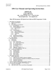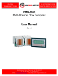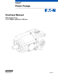
1
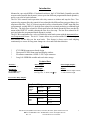
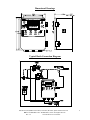
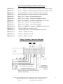
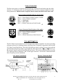
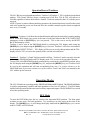
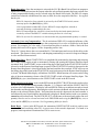
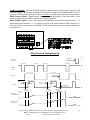
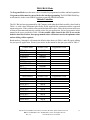
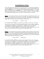
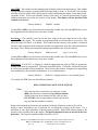
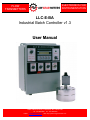
ELECTRONICS FOR INSTRUMENTATION FLOW TRANSMITTERS LLC-E-BA Industrial Batch Controller v1.3 User Manual 8809 Industrial Drive, Franksville, WI 53126-9337 Tel: 262-884-9800 Fax: 262-884-9810 E-Mail: [email protected] Web: http://www.awgearmeters.com LLC-E-BA INDUSTRIAL BATCH CONTROLLER MANUAL Rev. 1.3 (For LLC-BA Software Version 1.15-1.19) Table of Contents Introduction....................................................... page 3 Features................................................ page 3 Technical Data...................................... page 3 Dimensional Drawings........................... page 4 Typical Batch Connection Diagram........ page 4 Input/Output Wiring Terminal Connections........ page 5 Wiring Terminal Connection Diagram... page 5 Sensor Connection................................. page 6 Sensor Connector Detail......................... page 6 Using a ΑSinking≅ Sensor........... page 6 Input Circuit Detail.................... page 6 Resistor Connection Detail........ page 6 LLC-E-BA Operation......................................... page 7 Initial Display Messages......................... page 8 Display Mode Selection......................... page 8 Display Modes...................................... page 9 RATE Display Mode................ page 9 TO1 Display Mode................... page 9 TO2 Display Mode................... page 9 BATCH Status Display Mode... page 9 TO1- Display Mode................. page 9 Operation/Reset of Totalizers................. page 10 Totalizer 1................................ page 10 Totalizer 2................................ page 10 Operating Modes............................................... page 10 RUN Mode........................................... page 10 Batch Operation........................ page 11 Automatic Over-run Comp....... page 11 Batch Start/Stop....................... page 11 Batch Reset ............................. page 11 Batch Selection/Activation......... page 11 mA Output .............................. page 12 Batch Timing Diagram.............. page 12 PROGRAM Mode ............................... page 13 Default Variables...................... page 13 Variable Table 1.......... page 13 Entering/Editing the Variables... page 14 Delay........................... page 14 Precut.......................... page 14 Gate TIME.................. page 15 0-set mA's................... page 15 KFR-factor.................. page 15 Decimal Point KFR...... page 16 Eng=g UNITS KFR...... page 16 KFT-factor.................. page 17 Decimal Point KFT...... page 17 Eng=g UNITS KFT...... page 18 Batch Programming.................. page 18 Limited Warranty Statement............................... page 19 AW-Lake Company 8809 Industrial Drive, Franksville, WI 53126 web: www.aw-lake.com Tel: 262-884-9800 Fax: 262-884-9810 Email: [email protected] REV. 1.3 LLC-E-BA Manual rev 3.3.10.DOC 2 Introduction Mounted in a pre-wired NEMA 12 industrial enclosure, the LLC-BA Batch Controller provides accurate and repeatable batch control, stores up to nine different programmable batch quantities, and is a rate, total or batch indicator. The LLC-BA controls batch operation with relay contacts to initiate and stop the flow. Two separate relay outputs allow the control of two solenoids with different flow rates providing a slow stop/start of the flow. The LLC-BA activates the low flow solenoid on the START input and after a programmed variable DELAY, the high flow solenoid is activated producing a combined high flow rate. The high flow solenoid is deactivated before the batch amount has been reached by means of the PRECUT variable reducing the flow for a slow stop. The low flow solenoid is deactivated when the programmed batch amount is reached. The LLC-BA compensates for a valve or fluid delay in the batch system with the Automatic Overrun Compensation feature. The A.O.C. feature detects any overrun and the LLC-BA anticipates and corrects for the delay on the next batch. This feature is always active and adapting continuously to correct for long-term changes in valves and fluid characteristics. Features * * * * 87C51FB Microprocessor based design Dust-proof LEXAN front panel and display window Flowmeter connection via MIL-C-5015 style connector Long Life EEPROM variable and total value storage Technical Data Sensor Supply Output: Approx. 20mA @ 18VDC Power Supply: 110VAC 60Hz Enclosure: NEMA 12 & 13 Display: LCD, 16 character alpha-numeric, .35 inch character height Sensor Input: Voltage triggered, 2.00 Vp-p min., 0 - 4KHz, 10KΩ imp. Main Board: 87C51FB μProcessor, EEPROM memory Two Form C Relay Outputs: Relay Contact Ratings Maximum Switched Power Resistive Load DC: 60W 125VA AC: Inductive Load DC: 30W 60VA AC: Maximum Switch Voltage 220V DC, 250V AC Maximum Switch Current 2A Rated Load Resistive Load DC: 30V, 2A 110V, 0.5A AC: Inductive Load DC: 30V, 1A 110V, 0.3A AC: AW-Lake Company 8809 Industrial Drive, Franksville, WI 53126 web: www.aw-lake.com Tel: 262-884-9800 Fax: 262-884-9810 Email: [email protected] REV. 1.3 LLC-E-BA Manual rev 3.3.10.DOC 3 Dimensional Drawings Typical Batch Connection Diagram AW-Lake Company 8809 Industrial Drive, Franksville, WI 53126 web: www.aw-lake.com Tel: 262-884-9800 Fax: 262-884-9810 Email: [email protected] REV. 1.3 LLC-E-BA Manual rev 3.3.10.DOC 4 Input/Output Wiring Terminal Connections TERMINAL 1 mA. [+] - Positive, isolated internally loop powered 4-20mA. output TERMINAL 2 mA. [- ] - Negative, isolated internally loop powered 4-20mA. output TERMINAL 3 Remote Start/Stop, to remote momentary contact (optional) TERMINAL 4 Remote Start/Stop, to remote momentary contact (optional) TERMINAL 5 Relay 2 N.C. Contact - No connection (typical) TERMINAL 6 Relay 2 N.O. Contact - to High Flow Solenoid (if used) TERMINAL 7 RELAY 2 COMMON - Connect to TERMINAL 11(110VAC) TERMINAL 8 Relay 1 N.C. Contact - No connection (typical) TERMINAL 9 Relay 1 N.O. Contact - to Low Flow Solenoid TERMINAL 10 RELAY 1 COMMON - Connect to TERMINAL 11(110VAC) TERMINAL 11 110VAC (GND) - to Terminals 7 & 10 TERMINAL 12 110VAC (NEUTRAL) - to Low & High Flow Solenoids TERMINAL 13 110VAC - GND (Line Cord) TERMINAL 14 110VAC - NEUT (Line Cord) TERMINAL 15 110VAC - HOT (Line Cord) Wiring Terminal Connection Diagram AW-Lake Company 8809 Industrial Drive, Franksville, WI 53126 web: www.aw-lake.com Tel: 262-884-9800 Fax: 262-884-9810 Email: [email protected] REV. 1.3 LLC-E-BA Manual rev 3.3.10.DOC 5 Sensor Connection The flow meter sensor is connected using the MS style connector located on the right side of the enclosure. If a flowmeter cable was not supplied, follow the sensor connector diagram for cable wiring instructions. Shielded cable is required! Do not connect the shield at the sensor end! Sensor Connector Detail (5-pin on current units) Pin A => Sensor Supply (isolated), approx. 18 VDC Pin B => Sensor Common (isolated) Pin C => Signal Input Pin D => NOT USED Pin E => Shield Connection (to Earth Ground ) Sensor Connector Detail (4-pin on older units) Pin A => Sensor Supply (isolated), approx. 18 VDC Pin B => Sensor Common (isolated) Pin C => Signal Input Pin D => Shield Connection (to Earth Ground ) Using a ΑSinking≅ Sensor The LLC-E-BA accepts an Αactive≅ or Αsourcing≅ sensor output as standard. For sensors providing an Αopen collector≅ or Αsinking≅ output, a pull-up resistor is required for operation as shown in the LLC Input Circuit Detail below. The value of the pull-up resistor is selected so as to not exceed the current rating of the pick-up output. Typical pull-up values range from 2.2KΩ to 5.1KΩ. The LLC-EBA enclosure must be opened to install the pull-up resistor. The resistor is installed on the rear of the LLC display module to terminals 1 and 3 on the upper connector. See Resistor Connection Detail below for pull-up resistor installation. LLC Input Circuit Detail Resistor Connection Detail AW-Lake Company 8809 Industrial Drive, Franksville, WI 53126 web: www.aw-lake.com Tel: 262-884-9800 Fax: 262-884-9810 Email: [email protected] REV. 1.3 LLC-E-BA Manual rev 3.3.10.DOC 6 LLC-BA/E Operation MODE switch, momentary. Selects display mode. Power Indicator Light Power Switch Programming keys, used for entering parameters, batch values, and for reset of totalizers. BATCH START/STOP switch, momentary. Used to START or PAUSE currently selected batch. SELECT BATCH switch, momentary. Used to select and activate a batch #. (#’s 1-9). RUN/PROG key-switch, used for programming and totalizer reset. Set to RUN for normal operation. The key can be removed in this position to prevent accidental or unauthorized programming or reset of Totalizer 2. RESET BATCH switch, momentary. Halts current batch and resets batch counter to zero. AW-Lake Company 8809 Industrial Drive, Franksville, WI 53126 web: www.aw-lake.com Tel: 262-884-9800 Fax: 262-884-9810 Email: [email protected] REV. 1.3 LLC-E-BA Manual rev 3.3.10.DOC 7 Initial Display Messages The LLC displays some initial messages at power up. After 5 seconds the LLC will briefly display ***AW Company*** and then the following four variables for approximately 2 seconds each. After these brief displays, the LLC will display RATE or the last selected Mode. VERSION a w 1 . XX - Indicates the software version installed in the LLC. ON COUNT -> 00000XX - ΑON≅ count indicator increments each power-on cycle of the LLC. LEFT MEM%0000100 - Memory life indicator displays % of memory life remaining in 10% increments. The LLC stores programmed variables and retained totalizer values in EEPROM (electrically erasable memory), not a battery. Limits to the number of times memory can be re-written results in a minimum EEPROM life of 5 years with continuous use. This socket mounted memory IC is field replaceable and replacement memory ICs are available. Care must be used to insert the new memory IC in the exact same orientation as the one removed. Program variables require reprogramming after memory IC change. BLK LOC 0000XXX - Block Location, Used by LLC for EEPROM memory management. Display Mode Selection Display modes are selected differently in the PROGRAM Mode than in the RUN Mode. While in the PROGRAM Mode, pressing the [MODE]-key (UP) changes the display mode from one to the next. The [MODE]-key (UP) also selects which Totalizer may be reset while in the Programming Mode. When in RUN Mode, the Display Mode is selected by use of the momentary MODE toggle switch on the front of the enclosure in the upper left hand corner. The modes are indicated on the LLC-E-BA front label directly under the MODE switch in the order that they will appear. Pushing the MODE switch down and releasing it quickly will change the display from one mode to the next. Holding the MODE switch down causes the display to slowly scroll through the modes. The currently displayed mode is selected as the switch is released. The Display Modes are: RATE (display rate), T01 (display batch Total 1 as accumulating), T02 (display Totalizer 2), BATCH (display batch status), and T01(display batch Total 1 as depleting). The display mode can also be changed by pressing the [MODE]key (UP).The LLC will retain the last selected display mode. AW-Lake Company 8809 Industrial Drive, Franksville, WI 53126 web: www.aw-lake.com Tel: 262-884-9800 Fax: 262-884-9810 Email: [email protected] REV. 1.3 LLC-E-BA Manual rev 3.3.10.DOC 8 Display Modes RATE Display Mode - In the RATE display mode the unit will display the rate in engineering units based on the KFR factor with the decimal point at the selected location and the programmed engineering units at the end. The word RATE appears at the beginning of the display to indicate the selected display mode. A typical display would be: RATE 00000.34 GPM TO1 Display Mode - In TOTALIZER 1 display mode the LLC displays the total of the currently programmed BATCH in progress. Totalizer 1 is reset to zero on a START input when in RUN mode and will count up to the programmed batch amount. This total is retained by the LLC with the power removed. The display is based on the programmed KFT value, KFT engineering units, and decimal point. A typical display would be: TO1 000010.0 GAL TO2 Display Mode - In TOTALIZER 2 display mode the LLC displays the current total accumulating in Totalizer 2 (Grand Totalizer). Totalizer 2 accounts for all totalized flow and can only be reset in the PROGRAM mode. This total is retained by the LLC with the power removed. The display is based on the programmed KFT value, KFT engineering units and decimal point. A typical display would be: TO2 000496.8 GAL BATCH Status Display Mode - The BATCH status display mode indicates the state of the currently selected batch. This display indicates which batch is selected and whether the batch is RUNNING, PAUSED, or DONE. It does not indicate actual batch progress. A typical display would be: BATCH 1 DONE TO1- Display Mode (INVERSE TOTAL 1) - Displays batch quantity in currently selected batch when START input is closed and counts downward to zero at batch completion in the inverse function of Totalizer 1. Display is reset with Totalizer 1. This total is retained by the LLC with the power removed. The display is based on the programmed KFT value, KFT engineering units, and decimal point. A typical display would be: TO1- 00000.00 GAL AW-Lake Company 8809 Industrial Drive, Franksville, WI 53126 web: www.aw-lake.com Tel: 262-884-9800 Fax: 262-884-9810 Email: [email protected] REV. 1.3 LLC-E-BA Manual rev 3.3.10.DOC 9 Operation/Reset of Totalizers The LLC-BA has two independent totalizers, Totalizer 1 & Totalizer 2. TO1 is dedicated as the batch totalizer. TO2 (Grand Totalizer) keeps a running total of all flow. TO1 & TO2 will rollover at 9999900 regardless of where the decimal is located. Totals are retained by the LLC with the power removed. NOTE: If power is removed during totalizing operation, the retained totals may not reflect the actual total at the instant the power was removed since the variables retained at power down are updated once every 15 seconds. Totalizer 1 - Totalizer 1 is dedicated to the batch function and keeps the total of the currently running batch. In the RUN Mode reset occurs at the start of each batch when the BATCH START/STOP momentary switch or [BATCH]-key (SEL) are pressed. TO1 is also reset to zero by the RESET BATCH momentary switch. Totalizer 1 can be reset in the PROGRAM Mode by selecting the TO1 display mode using the [MODE]-key (UP) and pressing the [RESET]-key (DN) to reset. Totalizer 1 will reset to zero and will briefly display RESET TOTAL 1 . TO1 display will be reset to zero by this operation and the TO1display (inverse TO1) is reset to the quantity of the selected/activated batch. Totalizer 2 - Totalizer 2 (Grand Totalizer) totalizes all flow. Totalizer 2 can be reset only when the LLC is in the PROGRAM mode and TO2 display mode. TO2 is not reset by any other function. To reset TO2, select PROGRAM mode by turning the key switch to the vertical PROG position, select the TO2 display mode using the [MODE]-key (UP), and press the [RESET]-key (DN). Totalizer 2 will be reset by this operation and will start accumulating from zero. Use caution whenever in the PROGRAM mode to prevent accidental reset of the totalizer! Total 1 and Total 2 are retained by the LLC with the power removed. Operating Modes The LLC-E-BA has two operating modes, PROGRAM Mode and RUN Mode. The PROGRAM Mode is used for programming variables and batch quantities or for reset of Totalizer 2. The RUN Mode enables batch operation and the associated switches, inputs and outputs. The RUN/PROG key switch selects the operating mode. RUN Mode To enter the RUN Mode place the key switch in the horizontal RUN position. The front panel switches are now active for batch operation. Two touch-keys are also active on the front of the display. The [MODE]-key (UP) will change the display mode and the [BATCH]-key (SEL) can be used to START or STOP a batch. AW-Lake Company 8809 Industrial Drive, Franksville, WI 53126 web: www.aw-lake.com Tel: 262-884-9800 Fax: 262-884-9810 Email: [email protected] REV. 1.3 LLC-E-BA Manual rev 3.3.10.DOC 10 Batch Operation - Once the start input is activated, the LLC-BA Batch Unit will activate outputs to initiate flow and then deactivate the outputs when the selected batch quantity has been reached. One of nine programmable batches can be selected using the Batch Select input. The RELAY outputs control two solenoids with different flow rates to allow for a slow stop/start of the flow. In a typical batch cycle: RELAY1 Output (low flow solenoid) is activated by the START/STOP switch, remote start/stop input or the [BATCH]-key (SEL). After a programmed variable DELAY time, RELAY2 Output (high flow solenoid) is activated producing a combined high flow rate. RELAY2 Output (high flow solenoid) is deactivated before the batch quantity has been reached by means of the PRECUT variable reducing the flow for a slow stop. RELAY1 (the low flow solenoid) is de-activated when the programmed batch quantity is reached. Automatic Over-run Compensation - The de-activation of RELAY1 is under the influence of the Automatic Over-run Compensation feature that compensates for a valve or fluid delay in the batch system. For example, if a valve with a .5 second reaction delay is used on a 1000cc. batch, the first quantity delivered will be approx. 1020cc. depending on flow rate. The A.O.C. feature detects this over-run and the LLC-BA anticipates and corrects for the delay on the next batch. This feature is always active and adapting continuously to correct for long term changes in valve and fluid characteristics. Batch Stop/Start - Batch START/STOP is accomplished by momentarily depressing and releasing the START/STOP toggle switch or momentarily closing and opening the Remote Start/Stop Input (terminals 3&4). Batch START occurs on the rising edge of the signal as the START/STOP switch is released or as the Remote Start/Stop Input is opened. If the START/STOP switch is depressed or the Remote Start/Stop Input is closed again before the batch total has been reached, STOP will occur on the falling edge of the signal as the START/STOP switch is depressed or the Remote Start/Stop Input is closed. The Batch Status display will indicate PAUSED. Batch function will resume on the rising edge of the next momentary closure of the STOP/ START switch or Remote Start/Stop Input. The [BATCH]-key (SEL) also functions as the STOP/START switch in the RUN mode. Batch Selection/Activation - Active in the RUN mode, the SELECT BATCH switch is used to select and activate a programmed batch number (Batches 1- 9). Depress and hold the SELECT BATCH switch to select a batch number. The display will read SEL B# 000xx.xx to indicate currently selected batch number and batch quantity. Releasing the switch activates the Batch selection and returns the display to the selected Display Mode. Each time that the switch is depressed, the batch number is incremented by one. Repeat until the desired batch is displayed. Batch numbers with a zero quantity cannot be selected/activated. The BATCH SELECT will advance to the next batch with a non-zero quantity. Batches can be selected/activated in the PROGRAM mode using the [BATCH]-key (SEL) to select and the (ENT)-key to activate. See Programming Mode for details. Batch Reset - Active in the RUN mode, the momentary RESET BATCH switch is used to reset batches. The batch totalizing value T01 is reset to zero as the switch is depressed. If a batch is in progress, batch operation is terminated and T01 is reset to zero. AW-Lake Company 8809 Industrial Drive, Franksville, WI 53126 web: www.aw-lake.com Tel: 262-884-9800 Fax: 262-884-9810 Email: [email protected] REV. 1.3 LLC-E-BA Manual rev 3.3.10.DOC 11 mA=s (+/-) Output - Active in the RUN mode, this analog output is batch progress signal or with software revision 1.18 or higher can alternately indicate the currently selected batch number. The mA output is available on terminals 1&2. See the O-set mA=s variable description for more information. Batch Progress Signal – Signal directly corresponds with the progress of the batch where 4 mA equals zero progress and 20mA is equal to the full batch amount. Batch Number Signal – Value of mA indicates batch number in one mA increments with 5 – 13 representing batch numbers 1-9. To assign the output to the Batch Number Signal function it is necessary to wire a jumper to the back of the LLC-BA controller between lower connector terminal 11 and terminal 13. Batch Function Timing Diagram BATCH R ES E T BATCH R ES E T START STOP START START START/ STOP LO W FLO W LO W FLO W BATCH D ONE R EL AY 1 H IG H F L O W D EL AY H IG H F L O W D EL AY R EL AY 2 P RE C UT BAT CH T O TAL S LO W START S LO W START S LO W STOP BATCH PRO GRESS 0 20 mA A NA LO G OU TPUT 4 m A ( ty p .) AW-Lake Company 8809 Industrial Drive, Franksville, WI 53126 web: www.aw-lake.com Tel: 262-884-9800 Fax: 262-884-9810 Email: [email protected] REV. 1.3 LLC-E-BA Manual rev 3.3.10.DOC 12 PROGRAM Mode The Program Mode is used to enter, edit, or examine the programmed variables and batch quantities. Program variables must be entered before the batch programming. The RUN/PROGRAM keyswitch must be in the vertical PROG position to enter the PROGRAM mode. Default Variables The LLC-BA has been programmed by AW Company with either the default variable values listed in Table 1 or with values determined specifically for the supplied flow transmitter and the requested engineering units. If the variable values are the defaults shown here, follow the directions in the next sections to determine and enter the variable values for your application. Record your entries in this manual in the space provided in Table 1. If the variable values found in the LLC-P are not the default values shown below, these programmed values will in most cases be the optimum values and no editing will be required. Batch numbers 1 through 9 will contain the default values shown in Table 1 and will require editing for your specific application. Record your entries in this manual in the space provided in Table 1. Variable Name DELAY PRECUT 0-SET mA.s GTIME[s] KFR DP KFR E-UNITS KFT KFT DP KFT E-UNITS KFT Default Value 00000.50 0000000. 0000x.xx 0000001 00100.00 00000.00 hz 0010000. 0000000. pul Programmed Value Batch Number BATCH #1 BATCH #2 BATCH #3 BATCH #4 BATCH #5 BATCH #6 BATCH #7 BATCH #8 BATCH #9 Default Value 100.00 000.00 000.00 000.00 500.00 000.00 000.00 000.00 900.00 Table 1 Programmed Value AW-Lake Company 8809 Industrial Drive, Franksville, WI 53126 web: www.aw-lake.com Tel: 262-884-9800 Fax: 262-884-9810 Email: [email protected] REV. 1.3 LLC-E-BA Manual rev 3.3.10.DOC 13 Entering/Editing the Variables The LLC-BA must be in the program mode to enter the variables. To enter the Programming Mode, turn the RUN/PROG key switch to the vertical PROG position. To enter or edit the variables, press and hold the [PROG]-key (ENT). The display will start flashing PROGRAMMING ????. When the display stops flashing, release the [PROG]-key (ENT). The LLC will now display the first variable, DELAY, and is ready for the user to enter, edit or examine the variables. After each variable is viewed/edited and the displayed value is stored, the LLC advances to the next variable. DELAY - This variable sets the delay time for Relay2 (high flow solenoid output) relative to the START input. Typical delays are from 0.00 to 4.00 seconds. This function is used in slow start applications where Relay1 (low flow solenoid output) is energized immediately at a START input and Relay2 (high flow solenoid output) is turned on after the DELAY time. Factory default is 00000.50 seconds Press and hold the (UP) or (DN)-key to increment or decrement the variable value. To increase the increment or decrement rate, while holding the (UP) or (DN)-key, press and hold the (SEL)-key for medium rate or the (ENT)-key for maximum rate. When the desired value is displayed, press the (ENT)-key to store the programmed value and advance to the next variable. NOTE: Always release (SEL) or (ENT)-key before releasing the (UP) or (DN)-key or the LLC will proceed to next variable leaving the last variable with an unpredictable value. PRECUT - This variable sets the batch quantity remaining when Relay2 (high flow solenoid output) is turned off. This variable is programmed using the KFT engineering units and decimal point. This function is used in slow stop applications where Relay2 (high flow solenoid output) is turned off a PRECUT amount before the total batch quantity is reached and Relay1 (low flow solenoid output) remains energized until the batch quantity is reached. Factory default is 0000000 pulses Press and hold the (UP) or (DN)-key to increment or decrement the variable value. To increase the increment or decrement rate, while holding the (UP) or (DN)-key, press and hold the (SEL)-key for medium rate or the (ENT)-key for maximum rate. When the desired value is displayed, press the (ENT)-key to store the programmed value and advance to the next variable. NOTE: Always release (SEL) or (ENT)-key before releasing the (UP) or (DN)-key or the LLC will proceed to next variable leaving the last variable with an unpredictable value. AW-Lake Company 8809 Industrial Drive, Franksville, WI 53126 web: www.aw-lake.com Tel: 262-884-9800 Fax: 262-884-9810 Email: [email protected] REV. 1.3 LLC-E-BA Manual rev 3.3.10.DOC 14 GateTIME - This variable sets the sampling time for display of the incoming frequency. This variable is programmed in complete seconds and the allowable range is from 1 to 30 seconds. This variable will only effect the update of the display and is useful in stabilizing the display when dealing with variations in flow. In low rate situations (below 10Hz.) the LLC converts automatically to pulse width measurement to increase the accuracy of the display. The display will not function if this variable is set to zero! Factory default is 0000001 seconds Use the (UP) or (DN)-key to increment or decrement the variable value. Press the (ENT)-key to store the programmed value and advance to the next variable. 0-set mA=s - This variable is used to set the lower range of the mA output and as a fine offset adjustment for the output. The variable is programmed with two decimal places of accuracy. The allowable range is 0.00mA. to 10.00mA.. This variable has been factory set to produce a measured 4.00mA. at the output but can be changed to suit the users application or for fine offset adjustment of the output. This variable only adjusts the analog output and does not effect the display. Factory default is 0000x.xx mA* *(typ. 3.9x to 4.0x) Use the (UP) or (DN)-key to increment or decrement the variable value. Press the (ENT)-key to store the programmed value and advance to the next variable. KFR-factor - For the LLC to display in a desired engineering unit such as GPM, an appropriate scaling factor must be programmed. This factor is the KFR factor. The KFR is calculated using the K-factor of the transducer being monitored. The K-factor is the number of impulses per engineering unit established by the transducer manufacturer or by a calibration test. Factory default is 00100.00 (Displays Hertz w/ two decimal places) To calculate the KFR factor use the following formula: KFR= TIME BASE CONSTANT/K-FACTOR Where: - 100 is the time base constant for eng. units per second 6000 is the time base constant for eng. units per minute 360000 is the time base constant for eng. units per hour K-FACTOR is the average number of pulses per desired eng. unit that the transducer produces. Remove the insignificant decimals often produced with this calculation as they will result in displays with a misleading level of precision far exceeding the accuracy of the meter. Use a maximum of four digits regardless of decimal point position! Enter KFR without regard to the location of the decimal point in the display. The desired decimal location is entered in the next procedure. The largest acceptable number for KFR is 65535. AW-Lake Company 8809 Industrial Drive, Franksville, WI 53126 web: www.aw-lake.com Tel: 262-884-9800 Fax: 262-884-9810 Email: [email protected] REV. 1.3 LLC-E-BA Manual rev 3.3.10.DOC 15 For example: A flowmeter has a K-factor 2053.7 imp/Gal and the display should read in Gal/Min. KFR = 6000 / 2053.57 = 2.921741 for GPM 292174 is > 65535! 29217 > 4 digits! 2922 is best! Enter 2922 for KFR. For this example, KFR=2.922, the decimal point is set to three decimal places in the next procedure. Press and hold the (UP) or (DN)-key to increment or decrement the variable value. To increase the increment or decrement rate, while holding the (UP) or (DN)-key, press and hold the (SEL)key for medium rate or the (ENT)-key for maximum rate. When the desired value is displayed, press the (ENT)-key to store the programmed value and advance to the next variable. NOTE: Always release (SEL) or (ENT)-key before releasing the (UP) or (DN)-key or the LLC will proceed to next variable leaving the last variable with an unpredictable value. DP for KFR - This variable selects the location of the decimal point in the KFR factor and the display. This display will always be zeros with a decimal point. Factory default is 00000.00 Use the (UP) or (DN)-key to move the decimal point left or right. Press the (ENT)-key to store the location and advance to the next variable. Eng=g UNITS KFR - The desired engineering units for display of rate are entered using up to three programmable characters or letters. Example: gpm Factory default is hz_ The first (left-most) character is programmed/edited first. To choose a letter press the (UP) or (DN)key until the desired character or letter appears. Press the (SEL)-key to enter the 1st character. Repeat the procedure for the 2nd character and enter with the (SEL)-key. Repeat for the 3rd character and store the last entry with the (ENT)-key. The next variable will display. AW-Lake Company 8809 Industrial Drive, Franksville, WI 53126 web: www.aw-lake.com Tel: 262-884-9800 Fax: 262-884-9810 Email: [email protected] REV. 1.3 LLC-E-BA Manual rev 3.3.10.DOC 16 KFT-factor - For the LLC to display in a desired engineering unit such as Gallons, an appropriate scaling factor must be programmed. This factor is the KFT factor. The KFT is calculated using the K-factor of the transducer being monitored. The K-factor is the number of impulses per engineering unit established by the transducer manufacturer or by a calibration test. Factory default is 0010000. (Displays total pulses w/ no decimals) To calculate the KFT factor use the following formula: KFT= 10000/K-FACTOR Where: - 10000 is a constant - K-FACTOR is the average number of pulses per desired eng. unit that the transducer produces. Remove the insignificant decimals often produced with this calculation as they will result in displays with a misleading level of precision far exceeding the accuracy of the meter. Use a maximum of four digits regardless of decimal point position! Enter KFT without regard to the location of the decimal point in the display. The desired decimal location is entered in the next procedure. The largest acceptable number for KFT is 65535. For example: A flowmeter has a K-factor 2053.7 imp/Gal and the display should read in Gallons. KFT = 10000 / 2053.57 = 4.869568 for Gallons 486957 is > 65535! 48696 > 4 digits! 4870 is best! Enter 4870 for KFT. For this example, KFR=4.870, the decimal point is set to three decimal places in the next procedure. Press and hold the (UP) or (DN)-key to increment or decrement the variable value. To increase the increment or decrement rate, while holding the (UP) or (DN)-key, press and hold the (SEL)key for medium rate or the (ENT)-key for maximum rate. When the desired value is displayed, press the (ENT)-key to store the programmed value and advance to the next variable. NOTE: Always release (SEL) or (ENT)-key before releasing the (UP) or (DN)-key or the LLC will proceed to next variable leaving the last variable with an unpredictable value. DP for KFT - This variable selects the location of the decimal point in the KFT factor and the display. This display will always be zeros with a decimal point. Factory default is 0000000. Use the (UP) or (DN)-key to move the decimal point left or right. Press the (ENT)-key to store the location and advance to the next variable. Eng=g UNITS KFT - The desired engineering units for display of rate are entered using up to three AW-Lake Company 8809 Industrial Drive, Franksville, WI 53126 web: www.aw-lake.com Tel: 262-884-9800 Fax: 262-884-9810 Email: [email protected] REV. 1.3 LLC-E-BA Manual rev 3.3.10.DOC 17 programmable characters or letters. Example: Gal Factory default is pul (for pulses) The first (left-most) character is programmed/edited first. To choose a letter press the (UP) or (DN)key until the desired character or letter appears. Press the (SEL)-key to enter the 1st character. Repeat the procedure for the 2nd character and enter with the (SEL)-key. Repeat for the 3rd character and store the last entry with the (ENT)-key. The LLC will exit to the Display Mode. This ends the variable programming procedure. The LLC-BA will display the currently selected mode. Batch Programming The LLC-BA must be in the PROGRAM mode to program batch quantities. Nine different batches (19) can be programmed. Program variables must be entered before the batch programming. Batch quantities are based on the programmed KFT value, KFT engineering units and decimal point. NOTE: The maximum value that can be entered for a batch is 429496 regardless of decimal place. Values greater than 429496 will not be accepted. The more decimal places in the KFT, the smaller the batch that can be programmed. To program larger batches it may be necessary to reduce the number of decimal places in the KFT. Example: KFT = 214.38 and desired batch is 6000.00. Ignoring decimal location the value of 600000 is greater than 429496 and will not be accepted. The solution is to reduce the decimal places of the programmed KFT. With KFT changed to 214.4, batch will be 6000.0. Ignoring decimal location the value of 60000 is now less than 429496 and will be accepted. To program a batch quantity, press the [BATCH]-key (SEL). The display will momentarily read SET BATCH-->1 and then display BATCH1-> 0000000. Pressing the (SEL)-key again will increment the batch number. With a batch selected, press and hold the (UP) or (DN)-key to increment or decrement the batch quantity. To increase the increment or decrement rate, while holding the (UP) or (DN)-key, press and hold the (SEL)-key for medium rate or the (ENT)-key for maximum rate. NOTE: Always release (SEL) or (ENT)-key before releasing the (UP) or (DN)-key or the LLC may return to the Display Mode leaving the batch quantity with an unpredictable value. When the desired batch quantity is displayed, press the (ENT)-key to store the programmed value. This will also activate the selected batch number and the LLC unit will return to the Display Mode. To program another Batch quantity, repeat the above procedure. The [BATCH]-key (SEL) and (ENT)-key can be used for batch selection /activation when in the PROGRAM mode. When programming is completed, the RUN/PROG key switch must be returned to the horizontal RUN position to enter the RUN mode and execute any selected/activated batch. This ends the batch programming procedure. The LLC-BA will display the currently selected mode. To initiate batch operation, the RUN/ PROGRAM key switch must be set to the horizontal RUN position to enter the RUN mode. AW-Lake Company 8809 Industrial Drive, Franksville, WI 53126 web: www.aw-lake.com Tel: 262-884-9800 Fax: 262-884-9810 Email: [email protected] REV. 1.3 LLC-E-BA Manual rev 3.3.10.DOC 18 LIMITED WARRANTY AW-Lake Company warrants the LLC-E-BA to be in good working order for a period of 1 (one) year from the date of purchase from AW-Lake Company or an Authorized AW-Lake Company distributor. Should the LLC-E-BA fail to be in good working order at any time during this 1-year warranty period, AW-Lake Company will, at its option, repair or replace the LLC-E-BA at no additional charge as set forth below. Repair parts and replacement products will be furnished on an exchange basis and will be reconditioned or new. All replaced parts and products become the property of AW-Lake Company. This limited warranty does not include service or repair of damage to the LLC-E-BA resulting from accident, abuse, or modification by other than AW-Lake Company. Limited Warranty service may be obtained by delivering the LLC-E-BA during the 1 year warranty period to AW-Lake Company and providing proof of purchase date. If this product is delivered by mail, you agree to insure the LLC-E-BA or assume the risk of loss or damage in transit, to prepay shipping charges to warranty location, and to use the original shipping container or equivalent. For further information contact: AW-Lake Company 8809 Industrial Dr. Franksville , WI 53126 phone: (262) 884-9800 fax: (262) 884-9810 E-Mail: [email protected] All express and implied warranties for this product including the warranties of merchantability and fitness for particular purpose, are limited in duration to a period of 1 (one) year from date of purchase, and no warranties, whether express or implied, will apply after this period. In States that regulate the length of an implied warranty, the above limitations may not apply. If this product is not in good working order as warranted above, your sole remedy shall be to have the unit repaired or replaced as provided above. In no event will AW-Lake Company be liable to you for any damages, including any lost profits, lost savings or incidental or consequential damage arising out of the use or inability to use such product even if AW-Lake Company has been advised of the possibility of such damages, or for any claim by any other party. AW-Lake Company 8809 Industrial Drive, Franksville, WI 53126 web: www.aw-lake.com Tel: 262-884-9800 Fax: 262-884-9810 Email: [email protected] REV. 1.3 LLC-E-BA Manual rev 3.3.10.DOC 19