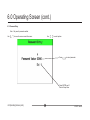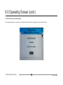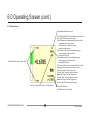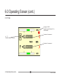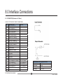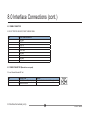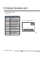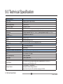
1
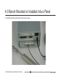
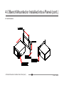
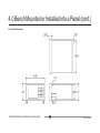
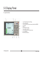
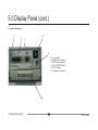
SI3300
4-20mA/DC-Digital Display
4-20mA/DC-Digital Display
The SI3300 is a member of the SI3000 Readout Family.
All members of the family are marked SI3000 on the front panel.
This manual is specifically for the SI3300 Model with 4-20mA/DC Voltage Inputs
user and installation manual
Index
Section
1.0
Title
Page
Index . . . . . . . . . . . . . . . . . . . . . 1
2.0
Safety Summary . . . . . . . . . . . . . . . . 2
Warnings and Cautions . . . . . . . . . . . 2
3.0
Service and Repair . . . . . . . . . . . . 4
4.0
4.1
4.2
4.3
4.4
Bench Mounted or Installed into a Panel . . . 5
Bench Mounted with associated Solartron Probes
and power supply . . . . . . . . . . . . . . . 5
Panel Mounting . . . . . . . . . . . . . . 6
Panel Dimensions . . . . . . . . . . . . . 7
Assembly Dimensions . . . . . . . . . . . 8
5.0
5.1
5.2
5.3
6.0
6.1
6.2
6.3
6.4
6.5
6.5.1
6.6
6.7
6.8
6.9
6.10
Index
Display Panel . . . . . . . . . . . . . . . . 9
Layout of Front Panel . . . . . . . . . . . . 9
Layout of Rear Panel . . . . . . . . . . . . 10
Overview of Features . . . . . . . . . . . . . . 11
Operating Screen . . . . . . . . . . . . . . 13
MENUS and SETUPS . . . . . . . . . . . . 14
Probe Menu Channel A . . . . . . . . . . . . 15
Probe Menu Channel B . . . . . . . . . . . . 16
Measurement Menu Page 1 . . . . . . . . . . . . 17
Measurement Menu Page 1 (cont.) . . . . . . 18
Measurement Menu Page 1 (cont.) . . . . . . 19
Measurement (Distance) Menu Page 2 . . . . 20
Measurement (Angle) Menu Page 2 . . . . . . 21
Limit Menu . . . . . . . . . . . . . . . . . . . . . 22
Input/Output Menu . . . . . . . . . . . . . . . 23
Serial Port Menu . . . . . . . . . . . . . . . 24
Section
6.11
6.12
6.13
6.14
6.15
6.16
6.17
6.18
6.19
6.20
Title
Page
Display Menu Screen 1 . . . . . . . . . . . . . . . 25
Display Menu Screen 2 . . . . . . . . . . . . . . . 26
Utilities Menu . . . . . . . . . . . . . . . . . 27
Password Menu . . . . . . . . . . . . . . . . 28
Password Entry . . . . . . . . . . . . . . . . . . . . 29
Utilities Menu (Factory Default Restore) . . 30
Operator Screen . . . . . . . . . . . . . . . 31
X Y Mode . . . . . . . . . . . . . . . . 32
Logging Menu Page 1 . . . . . . . . . . . . 33
Logging Menu Page 2 . . . . . . . . . . . . 34
7.0
7.1
7.1
7.1
7.2
RS232
RS232
RS232
RS232
RS232
User Input Commands . . . . . . .
User Input Command Details . . . .
User Input Command Details (cont.) .
User Input Command Details (cont.) .
Output Formats . . . . . . . . . . . . . . . .
35
36
37
38
40
8.0
8.1
8.2
8.3
8.4
Interface Connections . . . . . . . . . . . .
I/O Connector . . . . . . . . . . . . . . .
Communications Connector RS232 . . . .
Power Connector . . . . . . . . . . . . .
Analogue Voltage and Current Inputs . . . .
41
41
42
42
43
9.0
Technical Specifications . . . . . . . . . 44
Return Of Goods
Solartron Sales Offices
1
502810 issue 6
2.0 Safety Information
Terms in this Manual
WARNING statements identify conditions or practices that could result in personal injury or loss of life.
CAUTION statements identify conditions or practices that could result in damage to the equipment or other property.
Symbols in this Manual
This symbol indicates where applicable cautionary or other information is to be found.
Service Safety
This equipment has been designed and tested to meet the requirements of the Low Voltage Directive (1997) and has been supplied in a safe condition.
This manual contains information and warnings that must be followed by the user to ensure safe operation and to retain the apparatus in a safe condition.
Power Source
24v +/-10% DC 0.625A
2.0 Safety Information
2
502810 issue 6
2.0 Safety Information (cont.)
WARNINGS:
Do not operate in an explosive atmosphere
Do not remove covers or panels
To avoid personal injury, do not remove covers and panels. Do not operate the equipment without the covers and panels fitted. There are no internal
adjustments required during commissioning of the equipment.
Grounding the Equipment
The unit is supplied by 24V DC and therefore does not require an earth grounding cable to avoid electric shock. However it is recommended that the unit is
properly grounded to a known good earth via the bolt at the rear of the SI3300 to meet the full specification and EMC requirements.
2.0 Safety Information (cont.)
3
502810 issue 6
3.0 Service and Repair
This equipment contains no user serviceable parts.
This equipment must be returned to your Solartron dealer for any service and repair.
The SI3300 is designed to be maintenance free. Contact with solvents should be avoided. Any attempt to dismantle the
SI3300 will invalidate the warranty.
The SI3300 is a precision instrument and should be handled with care.
3.0 Service and Repair
4
502810 issue 6
4.0 Bench Mounted or Installed into a Panel
4.1 Bench Mounted with associated Solartron Probes and power supply
4.0 Bench Mounted or Installed into a Panel
5
502810 issue 6
4.0 Bench Mounted or Installed into a Panel (cont.)
4.2 Panel Mounting
- Ensure that there is sufficient space behind the relevant instrument panel for the SI3300 and its cabling (refer to section 4.3 for dimensions).
- Cut out the panel aperture to the dimensions shown.
- Working from behind the panel, with the box fully located, fit the side brackets to the studs and slide them forward toward the panel until they lock into
place.
- Screw the brackets to the panel.
CAUTION: Do not over tighten the screws as this may damage the case of the instrument.
WARNING: On installing or removing the SI3300, you must be aware of any hazardous equipment or materials in the vicinity. Make sure that any
equipment into which the SI3300 system is to be installed is switched off and made safe.
CAUTION: Avoid installing the SI3300 close to switch gear, contactors or motor starters.
CAUTION: Do not place other signal and power supply wiring in the same loom as the SI3300 wiring.
CAUTION: Use screened cables for all leads, with the screen earthed at one end only.
4.0 Bench Mounted or Installed into a Panel (cont.)
6
502810 issue 6
4.0 Bench Mounted or Installed into a Panel (cont.)
4.3 Panel Dimensions
4.0 Bench Mounted or Installed into a Panel (cont.)
7
502810 issue 6
4.0 Bench Mounted or Installed into a Panel (cont.)
4.4 Assembly Dimensions
4.0 Bench Mounted or Installed into a Panel (cont.)
8
502810 issue 6
5.0 Display Panel
5.1 Layout of Front Panel
5.0 Display Panel
1
2
3
4
5
6
7
8
9
10
9
Liquid Crystal Operator Colour Display
Return to Setup Menu
Scroll Up (Moves cursor around screen), Apply Preset (ABS/PRE)
Print Option
Enter
Scroll Right (select option)
Track, Peak+, Peak-, Diff
Scroll Down (Moves cursor around screen)
Zero (ABS/TARE)
Scroll Left (select option)
502810 issue 6
5.0 Display Panel (cont.)
5.2 Layout of Rear Panel
11
14
12
13
15
11
12
13
14
15
16
Screen Earth
Input/Output Connection
RS232 Communications
24V DC ON/OFF Switch
24V DC Supply
Transducer Connections
16
5.0 Display Panel (cont.)
10
502810 issue 6
5.0 Display Panel (cont.)
5.3 Overview of Features
Transducers
1 or 2 transducers may be connected
SI3100 Series LVDT
(Note: when setting up LVDT enter sensitivity in mV/V/mm regardless of final choice of measurement units)
SI3300 Series 4-20 mA or DC inputs (0-5 V, 0-10 V, ±5 V, ±10 V)
SI3500 Series – Orbit (Digital Probes and Linear Encoders)
Measurements
and Display
The SI3000 series can display in single measurement mode A, B, A+B, A-B, (A+B)/2, (A-B)/2 and (B-A)/a
The SI3300 and SI3500 series can display in dual measurement mode the sensor information A and B only; it is not possible to
display any combinational information in dual display mode.
(Note: (B-A)/a limited to ±2.5 deg.)
Limits
Upper and lower limits are set for each individual measurement channel (A and B) and for a combinational measurement (e.g. A+B)
The SI3000 series has 6 isolated open collector limit outputs which are allocated in accordance to the measurement mode.
Lower
Good
Upper
Lower
Good
Upper
A
Active
Active
Active
Off
Off
Off
B
Off
Off
Off
Active
Active
Active
A+B etc
Active
Active
Active
Active
Active
Active
If the measurement is within limit, then the good limit output is set, otherwise the upper or lower limit outputs are set to indicate a
reading out of limit.
5.0 Display Panel (cont.)
11
502810 issue 6
5.0 Display Panel (cont.)
5.3 Overview of Features (cont.)
Functions
The SI3000 series has the following functions available from the font panel keypad or controllable from the RS232 and some discrete
inputs.
Zero: Allows a reading to be set to zero (display shows TARE) all measurements are then referenced to the zero position.
Print: Allows measured data to be printed via the RS232 port.
Peak/Track Allows the readout to be switched from track mode to peak+ or peak-. In peak mode the displayed value will only change
if it is greater than (peak+) or less than (peak-) the current displayed value.
Menu (keypad only) accesses menu screens for set up.
The SI3300 and SI3500 series have the following additional functions:
Preset: Allows a preset value to be added to the displayed reading only – does not change the analogue outputs. Enable preset from
the preset menu and activate with the up arrow key.
In dual display mode it is possible to set the preset and zero to activate on both channels.
Log Mode: The readout can log and store data in three modes
Normal logging which will store a number of readings at a predefined interval. Setup and start from logging menu screen
Trigger start which will store a number of readings at a predefined interval, once the start logging input is triggered.
Log on Trigger which will store a reading every time the logging input is triggered, this mode is started from the logging menu.
Inputs
6 discrete inputs, Zero, Change from track to peak+ to peak-, print, log, real reset, preset.
Analogue Outputs
Analogue Output 1
Analogue Output 2
A
A
Off (null)
B
Off (null)
B
A+B etc.
A+B etc.
A+B etc.
Dual Display (SI3500 and SI3300 only)
A
B
Each analogue output can be independently set for 4-20 mA or a DC voltage (0-5 V, 0-10 V, ±5 V and ±10 V
5.0 Display Panel (cont.)
12
502810 issue 6
6.0 Operating Screen
Display seen directly after powering up
Note: This screen will vary depending on the Operator Screen displayed prior to powering down
Press MENU go to 6.1
6.0 Operating Screen
13
502810 issue 6
6.0 Operating Screen (cont.)
6.1 MENUS and SETUPS
Scroll up or down using the
keys to the required sub menu PRESS (ENTER)
Probes 6.2
Selects the type of probes to be
used with this instrument, the
parameters, channels and Identification associated with each probe.
Measurement 6.4
Selects Measurement type. A,B,(A+B) etc.
Measurement Mode (Track, Peak+, Peak-, Diff)
Reset Mode (Manual/Auto)
Trigger Time (0000 ms)
Peak Trigger Level (+/-000.00000xx)
Units (mm,inch for distance)(rad,deg for angle)
Unipolar/Bipolar (Auto Mode, Unipolar, Bipolar)
Distance 'n' (0001.0000) for angle
Limits 6.8
Sets up the Upper and Lower
measurement limits
Input/Output 6.9
Logic I/O + Analogue outputs
Print options
Serial Port 6.10
Sets up the parameters for the Serial RS232 Port.
Display 6.12
Set Language, Contrast,
Bar Offset, Bar
(+/-000.00000)
AutoRange (on/off)
Places After Decimal
point (0 to 6)
Utilities 6.13
Restore Factory Default Settings
Exit Menu 6.17
Shows Operator Screen
6.0 Operating Screen (cont.)
Shows current
Firmware version
14
502810 issue 6
6.0 Operating Screen (cont.)
6.2 Probes Channel A
Use
to move the cursor around the screen.
Use
to select options.
e.g. Extend + or Retract+
NONE, Voltage, Current
4-20mA, 0-5V, 0-10V, +/-5V, +/-10V
EXTEND +
Press ENTER to Edit parameter
To move cursor
To increment/decrement numbers
To change +/Press ENTER to Exit Mode
Press ENTER see 6.3
Channel B
Notes
Press MENU to return to the Operator Screen
With cursor over NEXT MENU Press ENTER for next sub Menu
With cursor over EXIT MENU Press ENTER to return to Setup Menu
6.0 Operating Screen (cont.)
15
502810 issue 6
6.0 Operating Screen (cont.)
6.3 Probes Channel B
Use
to move the cursor around the screen.
Use
to select options.
e.g. Extend + or Retract+
NONE, Voltage, Current
4-20mA, 0-5V, 0-10V, +/-5V, +/-10V
EXTEND +
Press ENTER to Edit parameter
To move cursor
To increment/decrement numbers
To change +/Press ENTER to Exit Mode
Press ENTER see 6.1
Channel B
Notes
Press MENU to return to the Operator Screen
With cursor over BACK Press ENTER for previous sub Menu
With cursor over EXIT MENU Press ENTER to return to Setup Menu
6.0 Operating Screen (cont.)
16
502810 issue 6
6.0 Operating Screen (cont.)
6.4 Measurement Menu Page 1
Use
to move the cursor around the screen.
Use
to select options.
A, B,A+B,(A+B)/2,A-B,(A-B)/2
(B-A)/a (Angle = limited to 5 deg)
PEAK + , PEAK -, or Diff
see 6.5 / 6.17
Press ENTER Go to
Measurement Menu Page 2 see 6.6
6.0 Operating Screen (cont.)
17
502810 issue 6
6.0 Operating Screen (cont.)
6.5 Measurement Menu Page 1
Use
to move the cursor around the screen.
Use
to select options.
Measure Type B,A+B,(A+B)/2,A-B,(A-B)/2,(B-A)/a
(Shows on Operator Screen in mm, inch for distance)
Measure Mode Track, Peak+, Peak-, Diff
Auto, Manual
Auto Mode only
Press ENTER to Edit parameter
To move cursor
To increment/decrement numbers
To change +/Press ENTER to Exit Mode
Press ENTER see 6.6
6.0 Operating Screen (cont.)
18
502810 issue 6
6.0 Operating Screen (cont.)
6.5.1 Measurement Menu Page 1
Use
to move the cursor around the screen.
Use
to select options.
Measure Type B,A+B,(A+B)/2,A-B,(A-B)/2, (B-A)/a
(Shows on Operator Screen in mm, inch for distance)
(Shows on Operator Screen in rad, deg for angle)
Measure Mode Track, Peak+, Peak-, Diff
Auto, Manual
Diff Mode only
Press ENTER to Edit parameter
To move cursor
To increment/decrement numbers
To change +/Press ENTER to Exit Mode
Press ENTER
6.0 Operating Screen (cont.)
19
19
502810 issue 6
6.0 Operating Screen (cont.)
6.6 Measurement Menu Page 2
Use
to move the cursor around the screen.
Use
to select options.
mm. inches, none
Bipolar, Unipolar or Auto Mode
Bipolar selected
Measurement range displayed Top + xx mm/inch
Bottom - xx mm/inch
Centrally Tracks the +/- measurements within limits in
green turning to red when outside the limits.
Unipolar selected
Measurement range displayed Top + xx mm/inch
Bottom 0 xx mm/inch
Tracks the + measurement within limit turning to red
when outside the limit.
Display filter 4 Hz, 8 Hz, 250 Hz, 1000 Hz
Press ENTER
Back to Setup Menu
6.0 Operating Screen (cont.)
20
502810 issue 6
6.0 Operating Screen (cont.)
6.7 Measurement (Angle) Menu Page 2
Use
to move the cursor around the screen.
Use
to select options.
Bipolar, Unipolar or Auto Mode
Bipolar selected
Measurement range displayed Top + xx rad/deg
Bottom - xx rad/deg
Centrally Tracks the +/- measurements within limits in
green turning to red when outside the limits.
Unipolar selected
Measurement range displayed Top + xx rad/deg
Bottom 0 xx rad/deg
Tracks the + measurement within limit turning to red
when outside the limit.
Auto Mode only
Press ENTER to Edit parameter
Press ENTER see 6.1
Back to Setup Menu
To move cursor
To increment/decrement numbers
To change +/Press ENTER to Exit Mode
6.0 Operating Screen (cont.)
21
502810 issue 6
6.0 Operating Screen (cont.)
6.8 Limit Menu
Use
to move the cursor around the screen.
Use
to select options.
3 types of limits can be displayed A,B and
"Computed Limits" when more than one
measurement type selected see 6.4
Press ENTER to Edit parameter
To move cursor
To increment/decrement numbers
To change +/Press ENTER to Exit Mode
Press ENTER see 6.1
Back to Setup Menu
6.0 Operating Screen (cont.)
22
502810 issue 6
6.0 Operating Screen (cont.)
6.9 Input/Output Menu
Use
to move the cursor around the screen.
Use
to select options.
Active High
Active High
0 to 10V, -5 to +5V
-10 to +10V 4-20mA
0 to 10V, -5 to +5V
-10 to +10V 4-20mA
Continuous
Press ENTER see 6.1
Back to Setup Menu
6.0 Operating Screen (cont.)
23
502810 issue 6
6.0 Operating Screen (cont.)
6.10 Serial Port Menu
Use
to move the cursor around the screen.
Use
to select options.
2400,4800,9600,19200,38400
7,8
0.5, 1.5,2
odd, even
C55
Press ENTER see 6.1
Back to Setup Menu
6.0 Operating Screen (cont.)
24
502810 issue 6
6.0 Operating Screen (cont.)
6.11 Display Menu - Screen 1
Use
to move the cursor around the screen.
Use
to select options.
Varies the screen
contrast for optimum
operator viewing screen
0,5,10,15,20,25,30,35,40,45,50,55
60,65,70,75,80,85,90,95,100
Offsets bar + or -
To move cursor
Press ENTER to Edit parameter
To increment/decrement numbers
Switches Bar Auto
Range On/Off
To change +/Press ENTER to Exit Mode
Sets places after
Decimal Point
This needs to be set
separately for CHA, CHB
+ Computed Measurement
(A+B, A-B etc.)
On
1,2,3,4,5,6
Press ENTER see 6.1
Back to Setup Menu
Press ENTER see 6.1
for next menu
6.0 Operating Screen (cont.)
25
502810 issue 6
6.0 Operating Screen (cont.)
6.12 Display Menu - Screen 2
Use
to move the cursor around the screen.
Use
to select options.
Use
On, Off
Press ENTER to Edit number
To move cursor
To increment/decrement number
To change +/Press ENTER to Exit Mode
Use
On, Off (see section 6.18)
Select Back/Exit Menu
Enter to Action
6.0 Operating Screen (cont.)
26
502810 issue 6
6.0 Operating Screen (cont.)
6.13 Utilities Menu
Use
to move the cursor around the screen.
Use
to select options.
Press ENTER
To Restore Factory Default Settings see 6.16
Set Password
Set up Data Log Mode
Press ENTER see 6.1
Back to Setup Menu
6.0 Operating Screen (cont.)
27
502810 issue 6
6.0 Operating Screen (cont.)
6.14 Password Menu
Use
to move the cursor around the screen.
Use
to select options.
Keys to turn On/Off
Default set to 1234
Use ENTER and
keys to change,
Press ENTER to confirm
Lock Menu, Lock ALL
Note: If Lock ALL is applied all keypad
functions are disabled except menu screen.
Press ENTER see 6.1
Back to Setup Menu
6.0 Operating Screen (cont.)
28
502810 issue 6
6.0 Operating Screen (cont.)
6.15 Password Entry
Note: Only seen if password enabled
Use
to move the cursor around the screen.
Use
to select options.
Press
to select parameter
Press ENTER see 6.1
Back to Setup Menu
6.0 Operating Screen (cont.)
29
502810 issue 6
6.0 Operating Screen (cont.)
6.16 Utilities Menu (Factory Default Restore)
The following is displayed for 3 seconds, the unit automatically defaults to factory setting and returns to the Operator Screen.
6.0 Operating Screen (cont.)
30
502810 issue 6
6.0 Operating Screen (cont.)
6.17 Operator Screen
Selected Measurement Menu see 6.3
Track PEAK+,PEAK-,DIFF Selected at Measurement menu see
6.3 or PEAK/TRACK membrane on keypad
TRACK Measures actual distance/angle within the set limits
displaying green. Turning red when outside the set limits. Returning to green when back inside the limits.
PEAK+ Measures within the set limits displaying green
turning red when outside the set limits.
Pressing ENTER resets
PEAK- Measures within the set limits displaying green
turning red when outside the set limits.
Pressing ENTER resets
DIFF measures Peak+, Peak-, measures within the set limits
displaying green turning red when outside of limits out
If manual set, Peak +/- Press enter to reset.
If Auto set, Peak + reset to probe actual position
Below Peak Trigger Time/Peak Trigger Level
If Auto set. Peak - reset to probe actual position
Above Peak Trigger Time/Peak Trigger Level
If Auto set, Diff - Diff zeroed every time period
Auto Range ON/OFF see 6.7 Display Menu
Press Zero to select ABS (Absolute) or TARE (Offset)
6.0 Operating Screen (cont.)
31
Selected by Limit Menu
Press MENU see 6.1 Set Up Menu
502810 issue 6
6.0 Operating Screen (cont.)
6.18 X Y Mode
Press Zero to TARE
Press
to apply Preset (see 6.7) or
ABS (Absolute)
Transducer X measurement
To select channel for Zero etc.
Transducer Y measurement
6.0 Operating Screen (cont.)
32
502810 issue 6
6.0 Operating Screen (cont.)
6.19 Logging Menu Page 1
Use
to select Standard,
Start on Discrete Input or Trigger on
Discreet Input
Use
Press ENTER
to edit number
to select On, Off
To Move Count
To Increment Number
Press ENTER
to Exit mode
6.0 Operating Screen (cont.)
33
502810 issue 6
6.0 Operating Screen (cont.)
6.20 Logging Menu Page 2
Use
to move to option
Press ENTER to Select option
6.0 Operating Screen (cont.)
34
502810 issue 6
7.0 RS232 User Input Commands
The unit shall respond to the following RS232 User Input Commands
Command
Command
Sequence
Number of
Parameter
Bytes
Description
Print
'^''O'
0
Print Mode = Normal : Standard print
Print Mode = C55 : C55 compatible print
(Print Mode option is located in the 'serial port' menu)
Extended Print
'^''P'
1
Print in SI3300 Format
Get Detail
'^''E'
2
Return Details about the SI3300
ABS or TARE, Measurement Type,
Unit of Measure, Limit Values
Set Unit
'^''S'
11
Set Various SI3300 Settings
Limits, Stroke, Measurement Type, Measurement Mode,
Zero, Start/Stop Continuous Print, Set Print Button Mode,
Notify, Stop Notify, Peak Reset, Discrete Inputs Active Hi/
Lo, Discrete Outputs Active Hi/Lo
Detailed Command specification with full parameter details follows on the next pages.
7.0 RS232 User Input Commands
35
502810 issue 6
7.0 RS232 User Input Commands (cont.)
7.1 RS232 User Command Details
In the following table sp is used to mean an Ascii space (Dec 32 Hex 20)
Shaded cells mean they are not used for the command shown
Command
Total No of Chars
1
2
3
4
Print
2
^
O
Extended Print
Current Measurement
Channel A
Channel B
3
3
3
^
^
^
P
P
P
0
1
2
4
^
E
A
0
4
^
E
M
0
4
4
4
4
4
4
4
4
4
4
4
4
^
^
^
^
^
^
^
^
^
^
^
^
E
E
E
E
E
E
E
E
E
E
E
E
U
L
L
L
L
L
L
L
L
S
S
S
0
0
1
2
3
4
5
6
7
0
1
2
GetDetail
Get Abs or Tare
Get Measurement
Mode
Get Unit of Measure
Get Current Mode LL
Get Current Mode UL
Get Computed LL
Get Computed UL
Get Channel A LL
Get Channel A UL
Get Channel B LL
Get Channel B UL
Get Computed Stroke
Get Channel A Stroke
Get Channel B Stroke
7.0 RS232 User Input Commands (cont.)
36
5
Character Number
6
7
8
9
10
11
12
13
502810 issue 6
7.0 RS232 User Input Commands (cont.)
7.1 RS232 User Command Details (cont.)
In the following table sp is used to mean an Ascii space (Dec 32 Hex 20)
Command
Total No of Chars
1
2
3
4
5
Character Number
6
7
8
9
SetUnit
Set Limits
Set Ch A UL
Set Ch A LL
Set Ch B UL
Set Ch B LL
Set Computed UL
Set Computed LL
13
13
13
13
13
13
^
^
^
^
^
^
S
S
S
S
S
S
L
L
L
L
L
L
A
A
B
B
C
C
U
L
U
L
U
L
1
0
1
0
1
0
.
.
.
.
.
.
2
7
2
7
2
7
Set Measurement Type
A
B
A+B
(A+B)/2
A-B
(A-B)/2
(B-A)a (angle)
13
13
13
13
13
13
13
^
^
^
^
^
^
^
S
S
S
S
S
S
S
M
M
M
M
M
M
M
0
1
2
3
4
5
6
sp
sp
sp
sp
sp
sp
sp
sp
sp
sp
sp
sp
sp
sp
sp
sp
sp
sp
sp
sp
sp
sp
sp
sp
sp
sp
sp
sp
7.0 RS232 User Input Commands (cont.)
37
10
11
12
13
3
8
3
8
3
8
4
9
4
9
4
9
sp
sp
sp
sp
sp
sp
sp
sp
sp
sp
sp
sp
sp
sp
sp
sp
sp
sp
sp
sp
sp
sp
sp
sp
sp
sp
sp
sp
sp
sp
sp
sp
sp
sp
sp
sp
sp
sp
sp
sp
sp
sp
sp
sp
sp
sp
sp
sp
sp
sp
sp
sp
sp
502810 issue 6
7.0 RS232 User Input Commands (cont.)
7.1 RS232 User Command Details (cont.)
Command
Total No of Chars
SetUnit
Set Measurement Mode
Track
Peak+
PeakDiff
X = Value eg 3.4 pad with spaces
Character Number
6
7
8
1
2
3
4
5
13
13
13
13
^
^
^
^
S
S
S
S
O
O
O
O
N
+
D
sp
sp
sp
sp
sp
sp
sp
sp
sp
sp
sp
sp
Zero
Peak Reset
Start Continuous Print
Stop Continuous Print
Set Print Key Single Mode
Set Print Key Cont Mode
13
13
13
13
13
13
^
^
^
^
^
^
S
S
S
S
S
S
Z
P
P
P
P
P
sp
E
R
R
R
R
sp
A
I
I
I
I
sp
K
N
N
N
N
Set I/O Logic State
Logic Inputs Active Low
Logic Inputs Active High
Logic Outputs Active Low
Logic Outputs Active High
13
13
13
13
^
^
^
^
S
S
S
S
I
I
I
I
-
I
I
O
O
Notify
Notify Probe Channel A
Notify Probe Channel B
Stop Notify
13
13
13
^
^
^
S
S
S
N
N
N
O
O
O
Zero Both
Zero One
Preset On
Preset Off
Set Preset Value
Preset Toggle
Peak Reset
5
5
13
13
13
13
13
T
T
S
S
S
S
S
Z
Z
R
R
R
R
R
0
1
:
E
0
0
O
O
±
T
S
7.0 RS232 User Input Commands (cont.)
38
9
10
11
12
13
sp
sp
sp
sp
sp
sp
sp
sp
sp
sp
sp
sp
sp
sp
sp
sp
sp
sp
sp
sp
sp
sp
sp
sp
sp
R
T
T
T
T
sp
E
C
S
M
M
sp
S
O
T
O
O
sp
E
N
O
D
D
sp
T
T
P
E
E
sp
sp
sp
sp
S
C
sp
sp
sp
sp
sp
sp
N
N
U
U
P
P
T
T
-
L
H
L
H
O
I
O
I
sp
sp
sp
sp
sp
sp
sp
sp
sp
sp
sp
sp
T
T
T
I
I
I
F
F
F
Y
Y
Y
H
C
C
A
H
H
L
A
B
T
sp
sp
sp
0
0
N
F
X
O
E
sp
F
X
G
T
sp
sp
X
G
sp
sp
sp
X
L
sp
sp
sp
X
E
sp
sp
sp
X
sp
sp
sp
sp
X
sp
sp
sp
sp
X
sp
sp
sp
sp
sp
sp
sp
502810 issue 6
7.0 RS232 User Input Commands (cont.)
7.2 RS232 Output Formats
PRINT OUTPUT FORMATS
C55 Compatible
Format
Example
Format
+0.00017mm
-0.0017mm
-0.017mm
NORMAL
+1.1308mm
-1.1308inch
-1.1308
-1.13mm
0
1
2
3
4
5
6
7
8
9
Sign Reading: right aligned, DP set by precision
+
0 ●
0
0
0
1
0 ●
0
0
1
7
0 ●
0
1
7
10
0
1
2
3
4
5
6
7
8
9
Sign Reading: right aligned, DP set by precision
+
1
●
1
1
●
1
1
●
1
1
10
3
3
3
●
11
12
Units
m
m
m
13
11
12
13
0
0
0
1
8
8
8
3
7
14
15
m
m
m
16
17
Limit
=
=
=
18
\n
\n
\n
\n
19
\r
\r
\r
\r
18
19
14 15 16 17
Units
m
m
i
n
c
h
m
m
20 21 22
Limit
\r
=
\r
=
\r
=
\r
=
\r
23
\n
\n
\n
\n
\n
Note. XY print is not available when C55 'Print Mode' is selected. In this case only the selected channel will be printed.
Where:
\r
\n
=space
= CR
= LF
7.0 RS232 User Input Commands (cont.)
39
502810 issue 6
7.0 RS232 User Input Commands (cont.)
7.2 RS232 Output Formats
0 1 2 3 4 5 6 7 8 9 10 11 12 13 14 15 16 17 18 19 20 21 22 23 24 25 26 27 28 29 30 31 32 33
Sign Reading: right aligned, DP set by precision
Units
Reading Type
Mode
\r \n
+
1 ● 1 3 0 8
m m
A B S
A
\r \n
i n c h
T A R E
B
P R E
A + B
The Extended Print is only available via remote RS232 commands (^P0 or ^P1 or ^P2). It is not selected, just requested.
Format
EXTENDED
+1.1308mm
Format
0
X
X= +1.1308mm X
and over limit
Y= -2.4215mm
and under limit
XY mode
1 2 3 4 5 6 7 8 9 10 11 12 13 14 15 16 17 18 19 20 21 22 23 24 25 26 27 28 29 30 31 32 33 34 35 36 37 38 39 40 41 42 43 44 45 46 47 48 49
: Sign Reading: right aligned, DP set by precision
Units
Limit
Y : Sign Reading: right aligned, DP set by precision
Units
Limit
\r \n
: +
1 ● 1 3 0 8
m m
>
Y : 2 ● 4 2 1 5
m m
<
\r \n
Note. XY print is not available when C55 'Print Mode' is selected. In this case only the selected channel will be printed.
Where:
=space
\r = CR
\n = LF
7.0 RS232 User Input Commands (cont.)
40
502810 issue 6
8.0 Interface Connections
8.1 I/O CONNECTOR (Mounted on I/O Board)
25 WAY D TYPE SOCKET, FIXED TO REAR PANEL
PIN
1
14
2
15
3
16
4
17
5
18
6
19
7
20
8
21
9
22
10
23
11
24
12
25
13
DESCRIPTION
CH1 OVER RANGE
CH1 IN RANGE
CH1 UNDER RANGE
CH2 OVER RANGE
CH2 IN RANGE
CH2 UNDER RANGE
Isolated O/P Common
‘Zero key’ Isolated I/P
‘Print key’ Isolated I/P
‘Reset key’ Isolated I/P
‘Peak key’ Isolated I/P
Log Control
'Preset Enable'
Isolated I/P Common
 Not Used
 Not Used
 Not Used
 Not Used
 Not Used
CH1 Analogue O/P Common
CH1 Analogue O/P
CH2 Analogue O/P Common
CH2 Analogue O/P
 Not Used
Not Used
8.0 Interface Connections
 DETAIL


CH1 O/P Return
CH1 Analogue O/P
CH2 O/P Return
CH2 Analogue O/P

ANALOGUE OUTPUT SPECIFICATION
Update interval
1.25mS
Bandwidth
500Hz
Rise time
70mS
Accuracy
0.1% FSO
41
502810 issue 6
8.0 Interface Connections (cont.)
8.2 COMMS CONNECTOR
9 WAY D TYPE PCB SOCKET, FIXED TO REAR PANEL
PIN
1
2
3
4
5
6
7
8
9
RS232 CONFIGURATION
 Not Used
RS232 Tx
RS232 Rx
 Not Used
RS232 GND
 Not Used
 Not Used
 Not Used
 Not Used
8.3 POWER CONNECTOR (Mounted on rear panel)
2.5 mm Chassis Mounted DC skt
PIN
1
2
DESCRIPTION
+24V DC Power IN(centre pin)
POWER RETURN
8.0 Interface Connections (cont.)
DETAIL
Power for Instrument routed through a switch
42
502810 issue 6
8.0 Interface Connections (cont.)
8.4 Analogue Voltage and Current Inputs
12 way terminal block
12 Way Screen Terminal Strip Mounted on Rear Panel
PIN
DESCRIPTION
1
+15V Output, 100mA Maximum
2
0V
3
-15V Output, 100mA Maximum
4
Channel A 4-20 mA Loop Source +
5
Channel A 4-20 mA Return
6
Channel A Voltage Input
7
Channel A Voltage Return
8
Channel B 4-20 mA Loop Source +
9
Channel B 4-20 mA Return
10
Channel B Voltage Input
11
Channel B Voltage Return
12
0V
8.0 Interface Connections (cont.)
Note: Pin 1 is to the right when viewed from rear
Pin 1
43
502810 issue 6
9.0 Technical Specification
MAIN INSTRUMENT
Display Type
Display Length (mm)
Display Length (inches)
Resolution - Display
Analogue Display
Keypad
Temperature
IP Rating
POWER SUPPLY
Voltage
Power
Colour LCD with integral backlight.
±ABCD.EFGH
±ABCD.EFGHJ
0.05µm or 0.000005”
Solid Vertical bar
9 key membrane keypad (Print, Zero, Peak/Track, Enter, Menu and navigation keys)
Storage temperature range: -20°C to +85°C, Operating temperature range: 0°C to +50°C
Front panel: IP65, Case: IP51
+24V DC ±10%
5 Watts maximum at 24V DC
(Universal 100-240V AC Input 24V DC PSU supplied with unit)
MECHANICAL
Weight
Dimensions
ELECTRICAL CONNECTIONS (Rear Panel)
DC Power
Input
Serial Comms (RS232)
Input/Output
Digital Inputs
1.1kg excluding transducers
See drawing
2.5mm DC Socket (Ctr pin +24V , Outer Return)
2 x 4-20mA or 2 x DC Input
9 way D type socket
25 way D type socket
4 off switch activated with common isolated return
Digital Outputs
6 off current sink with common isolated return, programmable ACTIVE HI or LO
Each pin can sink 500mA @ up to 40V
Analogue Outputs
1 for Channel A , 1 for Channel B,
Independent Channel Range selection of :
0 to 5V, 0 to 10V, ± 5V, ± 10V, 4 to 20 mA - Accuracy 0.1% FSO
9.0 Technical Specification
44
502810 issue 6