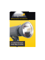
1
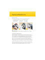
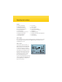
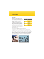
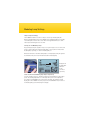
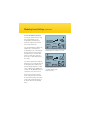
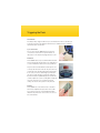
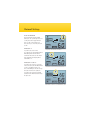
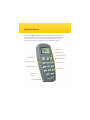
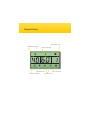
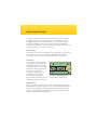
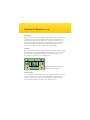
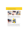
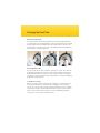
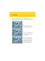
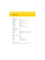
impact llighting ighting eequipment quipment and and accessories accessories VC-500LR Monolight INSTRUCTIONS Congratulations on your purchase of the Impact VC-500LR Monolight. We feel that it will contribute much to your photographic skill and enjoyment. This light incorporates numerous advanced features, and was designed to provide many years of trouble-free service. Please read these operating instructions and safety precautions carefully before operating this equipment. Features t $.04DIJQUFDIOPMPHZ t -BSHF-JRVJE$SZTUBM%JTQMBZ t 'JWF4UPQ3BOHFoGVMMQPXFSUPQPXFSJOGTUPQJODSFNFOUT t 'BTUSFDZDMJOHBOEMPOHýBTIEVSBUJPO t 3FNPUFDPOUSPMGPSVQUPNPOPMJHIUT t #VJMUJOPQUJDBMTMBWF t 3FE&ZF3FEVDUJPOGVODUJPO t i"VUP%VNQwFYDFTTQPXFSSFMFBTFDJSDVJUSZ t $PNNPOMZBWBJMBCMFwQMVHýBTITZODJOQVU t 'BODPPMFEBOEPWFSIFBUXBSOJOHDJSDVJUSZ t 6TFSSFQMBDFBCMFýBTIUVCF t -BNQ4BWJOH5FDIOPMPHZGPSFYUFOEFEMJGFPGNPEFMJOHMBNQ Power Requirements 5IJTMJHIUJTEFTJHOFEGPSVTFXJUI7"$QPXFSPOMZBOEJTTVQQMJFEXJUIB QSPOHHSPVOEFEQMVH%POPUBUUFNQUUPEFGFBUUIJTTBGFUZGFBUVSF*GOFDFTTBSZ VTFPOMZHSPVOEFEFYUFOTJPODPSETSBUFEGPSBNQTPSHSFBUFS Warning 5IFSFBSFOPVTFSTFSWJDFBCMFQBSUTJOTJEFUIFVOJU0OMZRVBMJåFETFSWJDFFOHJOFFST TIPVMEBDDFTTUIFJOTJEFPGUIFDBTF%BOHFSoIJHIWPMUBHFQBSUTJOTJEF "WPJEEBNBHF UPCPUIUIFýBTIUVCFBOENPEFMJOHMBNQ*GUIFNPEFMJOHMBNQPSýBTIUVCFCFDPNF DSBDLFEPSEBNBHFEJOBOZXBZUIFZTIPVMECFSFQMBDFEJNNFEJBUFMZ%POPUVTFZPVS ýBTIVOJUJOBOFOWJSPONFOUXIFSFNPJTUVSFPSýBNNBCMFWBQPSJTMJLFMZUPDPNFJO contact with the unit. Turn the power off and unplug the power cord when the unit is not JOVTF"MXBZTSFNPWFUIFNPEFMJOHMBNQBOESFQMBDFUIFQSPUFDUJWFDBQXIFO USBOTQPSUJOHUIFVOJU"WPJETUSPOHMJHIUGBMMJOHPOUPUIFTMBWFDFMMBTJUXJMMQSFWFOU FGåDJFOUPQFSBUJPO*GUIFVOJUCMPXTBGVTFBSFQMBDFNFOUGVTFDBOCFJOTFSUFEJOUIF QVMMPVUDPNQBSUNFOUPOUIFCBDLPGUIFVOJU5PFOTVSFMPOHMJGFPGUIFýBTIDBQBDJUPST UIFýBTIVOJUTIPVMECFQPXFSFEVQBOEåSFETFWFSBMUJNFTBUMFBTUFWFSZUXPNPOUIT 1SFQBSJOH:PVS.POPMJHIUGPS6TF Contents of carton Carefully remove the monolight from the box. You should have the following: t 7ýBTIIFBEXJUIQSPUFDUJWFDBQBOEýBTIUVCFJOTUBMMFE t 8NPEFMJOHMBNQ t HSJESFýFDUPS t TZODDBCMF t SFNPUFDPOUSPM t QPXFSDBCMF t VTFSNBOVBM 3 Mount on a stand 4FMFDUBTUBOEPSTVQQPSUTZTUFNPGTVJUBCMFXFJHIUBOEEJNFOTJPOTUPFOTVSFTUBCMF PQFSBUJPOPGUIFVOJU *OTUBMM3FýFDUPS.PEFMJOH-BNQ 3FNPWFUIFQMBTUJDDPWFSGSPNUIFMBUDIPOUPQPGUIFýBTIIFBE%FQSFTTUIFMBUDI QSFTTJOHJUUPXBSEUIFCBDLPGUIFVOJU3PUBUFUIFQSPUFDUJWFDBQDPVOUFSDMPDLXJTF1VMM UIFDBQPGGBOETFUBTJEF *OTUBMMUIFNPEFMJOHMBNQCZTDSFXJOHJUJOUPUIFUISFBEFE TPDLFU$"65*0/%POPUUPVDIUIFMBNQXJUIZPVSCBSFIBOET0JMSFTJEVFGSPNZPVS åOHFSTDBODBVTFUIFTVSGBDFPGUIFMBNQUPIFBUVOFWFOMZBOEFYQMPEF6TFXIJUFDPUUPO HMPWFTPSBDMFBODMPUI *OTUBMMUIFSFýFDUPSXIFSFUIFQSPUFDUJWFDBQXBTCFGPSF "MJHOUIFUISFFQFHTPOUIFSFýFDUPSXJUIUIFUISFFTMPUTQSFTTUIFSFýFDUPSJOBOESPUBUF DMPDLXJTFVOUJMJUMPDLTJOQMBDF5IFVNCSFMMBTMPUJOUIFSFýFDUPSTIPVMECFBUUIFCPUUPN /PUF5BLFDBSFXIFOåUUJOHPSSFNPWJOHSFýFDUPSTPSTPGUCPYFTUPOPUEBNBHFUIFýBTI UVCFBTTFNCMZ5IFýBTIUVCFJTWFSZEFMJDBUF"MXBZTTXJUDIPGGUIFVOJUBOEEJTDPOOFDU UIFQPXFSCFGPSFåUUJOHPSDIBOHJOHMBNQTýBTIUVCFTSFýFDUPSTPSTPGUCPYFT A B G C H D J E I F S O R K M L T Q P N Operating Instructions Legend A – Liquid Crystal Display B – Ready Beeper Indicator C – Modeling Lamp Indicator D – Error Indicator (shown off) E – Flash Ready Indicator F – Voltage Indicator G – Photo Cell Indicators (shown off) H – Modeling Lamp Readout I – Flash Power Readout J – Autodump Indicator K – Fuse Holder L – Sync Cord Jack M – Power Switch N – Power Regulator Knob O – Slave Sensor Control Button P – TEST Button Q – Audible Beep Button R – Modeling Lamp Independent Adjustment S – Power Socket T – Umbrella Holder Power Supply Before plugging the power cord into the wall socket, make certain that the power switch is set to the OFF (“O” position). Note: The VC-500LR monolight is designed to work on 110-120V 60Hz AC current. Power Switch Turn the power switch to the ON (“—“) position. A beep will sound and the LCD will show all of the current settings. We recommend charging the monolight for one hour prior to its initial use and after an extended period of inactivity (more than two weeks). If the unit is left unused for a few months, or the unit has been used predominately at low power settings, we recommend that the power be increased to the maximum and the unit left switched on (with the modeling lamp OFF) for at least 30 minutes, to help preserve the life of the capacitors. MODEL FLASH FLASH READY 110V AC Flash Settings Flash Output The flash power output is variable over a five f/stop range (six f/stops) from full power to 1/32 power in 1/10 f/stop increments. The power is displayed on the LCD screen in decimal form. The smaller top number represents the modeling lamp power, and the larger bottom number represents the flash power. Minimum setting is 1.0 and the maximum is 6.0. Rotating the regulator knob changes the value by 0.1 f-stop (a total of 50 values). If the current value is 5.6 and you want to reduce the power by one stop, set the power to 4.6. Setting Power 6.0 Full Power 5.0 1/2 Power 4.0 1/4 Power 3.0 1/8 Power 2.0 1/16 Power 1.0 1/32 Power To Set the Flash and Modeling Light Output Together Rotating the power regulator knob will adjust the power of both the flash and the modeling lamp unless you choose to set the power for each separately (more on that later). The READY icon will appear when the power is 80% recycled. We recommend you wait an extra second or two for 100% power. This will prolong the life of the capacitors. The flash is now ready to fire. To test, press the TEST button. When stepping down the power of the flash, the FLASH icon on the LCD screen will blink until the capacitors release the accumulated energy. MODEL FLASH FLASH READY 110V AC Modeling Lamp Settings Lamp Saving Technology The VC-500LR has built-in soft-start circuitry to ensure longer modeling lamp life. When the modelling lamp is turned on it will light up at a minimum brightness and slowly reach full brightness after a few seconds. This technology will allow the user to make fewer replacement lamp purchases over time. Settings for the Modeling Lamp By repeatedly pressing the regulator knob you can cycle through choices to set the same power for both the flash tube and the modeling lamp, to set the power for the flash and modeling lamp separately, or to have the modeling lamp off. When both the flash icon and the modeling lamp icon are displayed, turning the regulator knob will affect the power to both the flash tube and the modeling lamp. FLASH FLASH READY 110V AC Display shows modeling light and flash power controlled separately. To Set the Flash and Modeling Light Output Separately Press the regulator knob once. Turning the regulator knob now will affect only the flash power. The modeling lamp will be on continuously and its power can be adjusted by pressing the UP and DOWN arrows on the panel. In this mode, the modeling icon will display, but not the “MODEL” word. As you press the UP and DOWN arrows, the value of the modeling lamp’s power will change in the display. Modeling Lamp Settings (continued) To Turn the Modeling Lamp Off Pressing the regulator knob twice will turn the modeling lamp off. The modeling lamp icon will disappear. Turning the regulator knob now will affect only the flash power. Pressing the AUDIO button will turn the audible beeper off and will set the modeling lamp to turn off automatically when the flash is fired. The modeling lamp will turn back on when the flash unit has recycled and is ready to fire. The beeper icon will not display under this setting. Pressing the regulator knob a third time will return you to operating the flash and modeling lamp power simultaneously. The modeling light and flash icons will return, as will the words “MODEL” and ”FLASH.“ The VC-500LR will retain your settings after you power the unit off. Both increasing and decreasing the power settings generates heat inside the unit. Avoid repetitive power setting changes and you will extend the life of the unit, the flash tube, and modeling lamp. FLASH FLASH READY 110V AC Modeling light and ready beeper are OFF. MODEL FLASH FLASH READY 110V AC Modeling light and flash power are controlled simultaneously. Audio beep is ON. Triggering the Flash TEST Button The simplest way to trigger the flash is to press the TEST button. This is useful when you need to discharge the power built up in the flash unit, for example just before replacing the flash tube (more on that later). Sync Connection The sync jack on the VC-500LR may be used for direct connection to a camera set to ‘X’ synchronization. A radio slave receiver may also be plugged into this socket. Photocell The VC-500LR features a photocell which allows the flash unit to be triggered by another flash or to be triggered by a second or third flash to allow for anti-red eye preflashes. The photocell is located behind the red transparent cover on the top and at the back of the unit. The photocell is very sensitive but some experimentation with positioning may be necessary to ensure a reliable trigger, particularly if the cell is not in the direct line of sight of the triggering flash unit. Avoid directly illuminating the photocell from a continuous light source (such as ceiling lights or windows) since this can prevent correct operation. Very high ceilings can also affect the operation of the photocell. Sync connection Photocell Remote The VC-500LR also comes with a remote for situations where the monolight must be placed in an inaccessible area, or when you need to control multiple monolights simultaneously. Instructions for the remote are covered later in this manual. Remote Photocell Settings To Set the Photocell By repeatedly pressing the SLAVE button you can cycle through choices to set the photocell to trigger the flash after one, two or three flashes are detected. Or you can set the photocell to OFF. Photo Cell “1” If you have selected “1” in the procedure above, the unit will autoflash immediately when another flash is activated in the same area. The “flash bolt” will show in the display with a small number “1.” MODEL FLASH FLASH READY 110V AC The photocell is OFF. No autoflash. 1 MODEL DEL FLASH FLASH Photo Cell “2” and “3” If you have selected “2” in “To Set the Photocell” above, the unit will autoflash on the second flash the photocell detects and will ignore the anti-red eye flash, also known as the “preflash.” If you have selected “3” the unit will autoflash on the third flash detected by the photocell. READY 110V AC Autoflash set for the first flash detected. 2 MODEL FLASH FLASH READY 110V AC Autoflash set for the second flash detected. Audible Beep Settings A beep will sound once, when the flash is recycled and ready to flash. You can turn this audible beeper on and off by pressing the AUDIO button on the back panel. The musical notes symbol will display if the beeper is on, and will not display if the beeper is off. When the beeper is off, the modeling lamp will turn off automatically when the flash is fired. The modeling lamp will turn back on when the flash unit has recycled and is ready to fire. MODEL M FLASH FLASH READY 110V AC Audible beep is ON. Remote: Features The Impact VC-500LR Monolight includes a remote which allows you to control such things as flash power, the modeling lamp, audio beep, slave, and other functions from a distance. This remote can control up to seven VC-500LR monolights at a time and operates at a long range of up to 30m (98 ft) over the 2.4 GHz radio frequency. LCD Screen Power up button Power down button Power button Audio beep control Modeling lamp switch Slave switch Flash numbers (1 to 7) Test button Battery cover (in back) Lanyard attachment Remote: Display Flash number (1 to 7) Modeling lamp display Flash power display 1 2 Slave ON indicator Audio beep indicator 3 Slave OFF indicator Pre-flash indicators Synchronizing the Remote 1 Switch the flash head on and turn the flash power regulator until you get 5.5 on the LCD screen. Turn the flash head OFF. 2 While pressing the TEST button on the flash head, switch the flash head back ON. The display will light but will display “––” instead of digits. 3 Release the TEST button on the flash head. Press 1 on the remote and then immediately press the MODEL button. A beep will sound to confirm synchronization of the remote with monolight #1. Step 3 must be completed within 15 seconds or the flash head will reset, and you’ll have to begin the synchronization process again. To set up additional VC-500LR monolights, follow the steps above, but press a number from 2 to 7 instead of 1 in step 3. Operating the Remote It is possible to assign a number (1 to 7) to a single monolight or a group of monolights. For example, button number 1 on the remote can sync to one monolight or to as many VC-500LR monolights as you set up with that number. In an environment with many monolights controlled by the remote, it is a good idea to tag each monolight with its number for visual identification. Once you have synced a monolight to a remote, they will remain synced together after you power off the devices. Test Your Setup Press a number on the remote control and then press the Test button. If you have synced correctly and are in range, the corresponding monolight will flash. Pressing the test button on the remote is an easy way to recognize which flash you are adjusting. Flash Power Press the number of the monolight you want to adjust. The right box on the LCD will display the number of the monolight you are adjusting. Press the up and down arrow buttons to adjust the output of the flash. Each press of the button corresponds to a 1/10th of an f/stop. Hold down the buttons to rapidly increase/decrease output power. The large number in the middle of the LCD will display the output power of the flash. The number in the right box indicates which monolight is being adjusted Modeling Lamp Make certain you have selected the number of the monolight you want to adjust. Press the MODEL button on the remote to adjust the power of the modeling lamp. The number in the left of the LCD will display the modeling lamp power. Each button press will change the power of the modeling lamp one whole stop (from 1.0 to 6.0). Setting the modeling lamp power to 00 will turn the modeling lamp off. Operating the Remote (continued) Audio Beep Make certain you have selected the number of the monolight you want to adjust. Pressing the AUDIO button on the remote will toggle the audio beep of the monolight on and off. If the musical notes display in the bottom left of the remote’s LCD, the audio beep is on. Even if you select OFF for the audio beep, the monolight will still sound a confirmation beep as you make adjustments with the remote. The audio beep adjustment on the remote only controls the recycling confirmation beep of the monolight. Photocell Make certain you have selected the number of the monolight you want to adjust. Pressing the SLAVE button on the remote will toggle the Photocell selection. The icons along the bottom of the remote’s LCD indicate whether the monolight will respond to 1, 2, or 3 detected flashes, or whether the photocell (slave) is OFF. This display shows audio beep is active and the photocell (slave) is OFF. Troubleshooting In case of malfunction, the first thing to check is the condition of the batteries. Recharge or replace the batteries as necessary. If the monolight still does not respond to the remote, check the red photocell at the top of the monolight. If a red light shows in the photocell, turn the monolight off for 10-15 seconds, and turn it back on. Use of Umbrellas and Softboxes Umbrellas An umbrella with a handle diameter of 8-10mm can be firmly secured in the umbrella holder. Firmly press the umbrella shaft through the holder. The locking knob is located on the side. Do not overtighten to avoid damaging the shaft of the umbrella. The reflector supplied with the VC-500LR features a slot through which you can feed the umbrella shaft. Softboxes Use of a heavy accessory such as a large softbox can make the flash unstable. However, it is possible to re-balance the flash by sliding the flash unit along its mounting bracket. Release the screw at the top of the mounting bracket. Slide the flash unit along its mounting bracket towards the front of the flash so that the head doesn’t tilt down. Don’t forget to retighten the screw. Make certain that your setup is stable before proceeding. Changing the Flash Tube Discharge the Flash Unit The charge in the flash unit must be discharged before removing the flash tube. Make sure the flash unit is on. Push the TEST button on the rear panel of the flash. The unit will flash, discharging the power. Immediately turn off the power switch on the rear panel. Unplug the power cord from the power source. It is advisable to wait at least 30 minutes before touching or removing the flash tube. Remove Old Flash Tube First, remove the reflector. Then, using white cotton gloves or a clean cloth, remove the modeling lamp. You will need to remove the retention spring wrapped around the top of the flash tube. With needle-nose pliers, unhook the retention spring loop. Using white cotton gloves or a clean cloth, grip the base of the flash tube on each side. Carefully pull the flash tube from the flash unit. Install New Flash Tube Make sure the power switch is off and the power cord is disconnected from the source. Locate the two flash tube pin sockets above the modeling lamp socket. Using white cotton gloves or a clean cloth, push the pins of the flash tube into the sockets using firm, even pressure at the base of the flash tube. With needle-nose pliers, hook the retention spring over the hook above the flash tube. Re-insert the modeling lamp using white cotton gloves or a clean cloth. Re-install the reflector. Changing the Fuse A 6A fuse is mounted in the rear panel and protects the circuitry of the flash unit. Turn off the unit and disconnect the power supply before changing the fuse. Never replace with a fuse of a different type or rating. A spare 6A fuse is fitted within the fuse holder. Use a small screwdriver to release the fuse cover. Remove the old fuse, place the new fuse in the slot, then replace the fuse holder. Protection Features The VC-500LR is equipped with advanced overheating and overcharge warning and protection circuits to prevent damage to the internal electronics. Overheating Protection After a long shooting session at high output, the recycling time of the flash will increase automatically until the flash cools down to a safe level, and then will start working normally again. Overvoltage and Overcurrent Protection The flash is protected against unstable voltages. Overcurrent protection is especially useful when using a power pack. Best Practices As with any flash unit, the useful life of the flash tube and the unit as a whole depends on the way it is used. Avoiding excessive heat is the key to long life. t 5IFGBTUSFDZDMJOHGFBUVSFPGUIF7$TFSJFTBMMPXTBSBQJETFRVFODFPGIJHIQPXFS flashes. However, this feature should be used sparingly, since continuous rapid flashing can cause overheating and subsequent damage to the flash tube and possibly the internal electronics. t 3BQJETFRVFODFTPGýBTIFTTIPVMEBMXBZTCFGPMMPXFECZBSFBTPOBCMFDPPMJOHQFSJPE 10 to 20 minutes without flashing or at a substantially reduced rate. This flash is fitted with a cooling fan and will cool faster if left switched on with the modeling lamp off. t %JNNJOHPSUVSOJOHUIFNPEFMJOHMBNQPGGXJMMSFEVDFIFBUHFOFSBUJPO t "WPJESBQJEIJHIQPXFSýBTIJOHXIFOVTJOHSFTUSJDUJWFSFýFDUPSTTVDIBTTOPPUTPSHSJE reflectors, particularly if the unit is pointing downward. t %POPUýBTIPWFSTIPUTQFSNJOVUFGPSPWFSNJOVUFT t %POPUýBTIPWFSTIPUTQFSNJOVUFGPSPWFSNJOVUFT t 5BLFTQFDJBMDBSFXIFOTIPPUJOHJOBIJHIUFNQFSBUVSFFOWJSPONFOU Error Codes In the event of a malfunction, the LCD screen will display a blinking error code. The WARNING icon will also blink. In addition, errors codes E2 and E3 have a beep warning. Following is a short description of the three error codes and the necessary action to take. MODEL FLASH WARN FLASH READY 110V AC E1 Temperature Transducer problem. Turn the unit OFF immediately and contact the place where you purchased the flash. MODEL FLASH WARN FLASH READY 110V AC E2 This error code can display after a long shooting session at high output or rapid sequence. Turn OFF the flash and allow it to rest for 30 minutes. E3 MODEL FLASH WARN FLASH READY 110V AC This error code will display when the internal voltage of the flash is too high. Turn OFF the power immediately. After a few minutes turn on the flash again. If you still have the malfunction warning, turn OFF the unit and contact the place where you purchased the flash. 4BGFUZBOE.BJOUFOBODF/PUFT 4BGFUZ/PUFT t %POPUVTFZPVSýBTIJOBOFOWJSPONFOUXIFSFNPJTUVSF may come in contact with the unit. t "åSFIB[BSEFYJTUTJGýBNNBCMFNBUFSJBMTBSFQMBDFEJODMPTFQSPYJNJUZ UPUIFýBTIUVCFPSUIFNPEFMJOHMBNQ%POPUVTFZPVSýBTI JOBOFOWJSPONFOUXIFSFýBNNBCMFWBQPSTBSFQSFTFOU t %POPUSFTUSJDUUIFWFOUJMBUJPOIPMFTXIFOUIFýBTIJTJOVTF t "MXBZTTXJUDIPGGUIFQPXFSBOEEJTDPOOFDUUIFQPXFSDPSE CFGPSFDIBOHJOHUIFGVTFNPEFMJOHMBNQPSýBTIUVCF t "WPJEQMBDJOHDBCMFTXIFSFUIFZDBOCFUSJQQFEPWFS 3FQMBDFEBNBHFEDPSETJNNFEJBUFMZ t /FWFSVTFBýBTIVOJUXJUIEBNBHFEDPWFSTNPMEJOHTýBTIUVCF PSNPEFMJOHMBNQ*GUIFVOJUJTESPQQFEPSEBNBHFE IBWFJUDIFDLFECZBQSPGFTTJPOBMSFQBJSTFSWJDFCFGPSFVTJOH t %VFUPUIFIJHIWPMUBHFDJSDVJUSZJOTJEFUIJTEFWJDF EPOPUBUUFNQUUPEJTBTTFNCMFPSSFQBJSUIFVOJUZPVSTFMG t ,FFQPVUPGUIFSFBDIPGDIJMESFO .BJOUFOBODF/PUFT t 5VSOUIFQPXFSPGGBOEVOQMVHUIFQPXFSDPSEXIFOUIFýBTIJTOPUJOVTF t 8FSFDPNNFOEDIBSHJOHUIFýBTIVOJUGPSPOFUPUXPIPVSTQSJPSUPJUTJOJUJBMVTF BOEBGUFSBOFYUFOEFEQFSJPEPGJOBDUJWJUZNPSFUIBOUXPXFFLT t *GUIFVOJUJTMFGUVOVTFEGPSBGFXNPOUITPSUIFVOJUIBTCFFOVTFEQSFEPNJOBUFMZ BUMPXQPXFSTFUUJOHTXFSFDPNNFOEUIBUUIFQPXFSCFJODSFBTFE UPUIFNBYJNVNBOEUIFVOJUMFGUTXJUDIFEPOXJUIUIFNPEFMJOHMBNQ0'' PDDBTJPOBMMZGPSBUMFBTUNJOVUFTUPIFMQQSFTFSWFUIFMJGFPGUIFDBQBDJUPST t "WPJESBQJEIJHIQPXFSýBTIJOHFTQFDJBMMZXIFOVTJOHSFTUSJDUJWFSFýFDUPST TVDIBTTOPPUTPSHSJET&YDFTTJWFIFBUXJMMTIPSUFOUIFMJGFTQBOPGZPVSýBTIVOJU NPEFMJOHMBNQBOEýBTIUVCF 4QFDJåDBUJPOT VC-500LR Monolight 1PXFS0VUQVU Guide Number 0VUQVU$POUSPM3BOHF 3FDZDMJOH5JNF 'MBTI%VSBUJPO .PEFMJOH-BNQ 5SJHHFST Trigger Voltage $PMPS5FNQFSBUVSF Flash Tube Cooling Fan "VUP1PXFS%VNQ 0WFSWPMUBHF1SPUFDUJPO 0WFSDVSSFOU1SPUFDUJPO 0WFSIFBU1SPUFDUJPO 4ZOD$BCMF 1PXFS4PVSDF %JNFOTJPOT 8FJHIU 84 'VMMUPJOUIGTUPQJODSFNFOUT _TFDPOET _TFDPOE 8 4ZODDBCMFTMBWFTFOTPSUFTUCVUUPO 5V ¡,¡, Plug-in type, user replaceable Yes :FT :FT :FT :FT QIPOPKBDL _7)["VUPNBUJD7PMUBHF3FHVMBUJPO$JSDVJU YYYYDN owithout reflector MCLH VC-500LR Remote Control 3BOHF 'SFRVFODZ $IBOOFMT 1PXFS4VQQMZ %JNFOTJPOT 8FJHIU NGU ()[ Y"""CBUUFSZ YYYYNN P[H owithout batteries ª$PQZSJHIU(SBEVT(SPVQ (VJEF/VNCFSJTDBMDVMBUFEBUN*40VTJOHUIFJODMVEFESFýFDUPSBOEJTBTUBSUJOHQPJOU You should perform your own evaluations to determine the results you prefer. FCC Compliance for Wireless Remote This device complies with Part 15 of the FCC Rules. Operation is subject to the following two conditions: (1) this device may not cause harmful interference, and (2) this device must accept any interference received, including interference that may cause undesired operation. Warranty Impact provides a limited warranty that this product is free from defects in materials and workmanship to the original purchaser under normal use for a period of one (1) year from the original purchase date. Impact’s responsibility with respect to this limited warranty shall be limited solely to repair or replacement, at its option, of any product which fails during normal consumer use. This warranty does not extend to damage or failure which results from misuse, neglect, accident, alteration, abuse, improper installation or maintenance. To obtain a replacement during the time of this warranty, please return the defective item with proof of purchase along with an RMA number to the place of purchase. This warranty gives you specific legal rights, and you may also have other rights which vary from state to state. To see all of our lighting equipment, please visit our website. impact www.impactstudiolighting.com