1
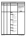
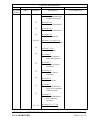
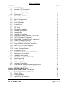
LOG OF REVISIONS Page Number Revision Number Date 1 03/18/11 All Description Complete Supplement FAA Approved Robert Grove Robert Grove ODA STC Unit Administrator GARMIN International, Inc. ODA-240087-CE Date: 2 12/18/12 6 8 Section 1.2 • Added capabilities checkboxes • Added GPS approaches without vertical • Added reference to EASA AMC 20-4 10 Section 1.3 • Removed suggestion for secondary charts • Changed to Type B Software in accordance with AC 120-76B. 10 Section 1.4 • Added ADS-B, AEG, FIS-B, NOTAM, TFR 12 Section 2.2 • Removed VFR only limitation 12 190-01007-A2 Rev. 3 Page 2 of 35 Table 1 • Added new functions 3/18/11 See Page 1 Section 2.3 • Clarified secondary navigation source requirement AFMS, Garmin GTN GPS/SBAS System FAA APPROVED LOG OF REVISIONS Revision Number Date Page Number Description 18 Section 2.14 • Modified datalinked weather limitations 18 Section 2.16 • Modified limitation 19 Section 2.17 • Modified limitation 19 Section 2.21 • New limitation 24 & 25 Section 3.2.8 and 3.2.9 • Modified section title 25 Section 3.2.10 • New section 26 Section 4.1 • Added telephone audio deactivation 27 27 29 31 32 34 - 35 FAA Approved Section 4.3 • Modified caution statement Section 4.4 • Added caution statement Section 4.6 • New section Section 7.7 • Added TCAD and GDL 88 as optional traffic systems Section 7.8 • Modified Heading Not Available operation Sections 7.12 – 7.16 • New sections AFMS, Garmin GTN GPS/SBAS System FAA APPROVED 190-01007-A2 Rev. 3 Page 3 of 35 3 03/26/13 190-01007-A2 Rev. 3 Page 4 of 35 20 Section 2.17 • Modified limitation See Page 1 AFMS, Garmin GTN GPS/SBAS System FAA APPROVED Table of Contents SECTION Section 1. GENERAL 1.1 Garmin GTN Navigators 1.2 System Capabilities 1.3 Electronic Flight Bag 1.4 Definitions Section 2. LIMITATIONS 2.1 Cockpit Reference Guide 2.2 Kinds of Operation 2.3 Minimum Equipment 2.4 Flight Planning 2.5 System Use 2.6 Applicable System Software 2.7 SD Card 2.8 Navigation Database 2.9 Ground Operations 2.10 Approaches 2.11 Autopilot Coupling 2.12 Terrain Proximity Function (All Units) 2.13 TAWS Function (Optional) 2.14 Datalinked Weather Display (Optional) 2.15 Traffic Display (Optional) 2.16 StormScope® Display (Optional) 2.17 Flight Planner/Calculator Functions 2.18 Glove Use / Covered Fingers 2.19 Demo Mode 2.20 Active Weather Radar 2.21 Telephone Audio Section 3. EMERGENCY PROCEDURES 3.1 Emergency Procedures 3.2 Abnormal Procedures Section 4. NORMAL PROCEDURES 4.1 Unit Power On 4.2 Before Takeoff 4.3 HSI and EHSI Operation 4.4 Autopilot Operation 4.5 Coupling the Autopilot during approaches 4.6 Telephone & SMS Text (Optional) Section 5. PERFORMANCE Section 6. WEIGHT AND BALANCE Section 7. SYSTEM DESCRIPTIONS 7.1 Pilot’s Guide 7.2 Leg Sequencing 7.3 Auto ILS CDI Capture AFMS, Garmin GTN GPS/SBAS System FAA APPROVED PAGE 7 7 9 11 11 13 13 13 13 14 16 16 16 16 17 17 18 18 18 19 19 19 20 20 20 20 20 21 21 22 26 26 26 27 27 28 29 29 29 30 30 30 30 190-01007-A2 Rev. 3 Page 5 of 35 7.4 7.5 7.6 7.7 7.8 7.9 7.10 7.11 7.12 7.13 7.14 7.15 7.16 Activate GPS Missed Approach Terrain Proximity and TAWS GMA 35 Audio Panel (Optional) Traffic System (Optional) StormScope® (Optional) Power Databases External Switches Airspace Depiction and Alerts GDL 88 ADS-B Traffic System Interface (Optional) GWX 70 Weather Radar (Optional) Charts (Optional) Transponder Control (Optional) 190-01007-A2 Rev. 3 Page 6 of 35 30 31 31 31 32 32 32 33 34 34 35 35 35 AFMS, Garmin GTN GPS/SBAS System FAA APPROVED Section 1. GENERAL 1.1 Garmin GTN Navigators The Garmin GTN navigation system is a GPS system with a Satellite Based Augmentation System (SBAS), comprised of one or more Garmin TSO-C146c GTN 625, 635, 650, 725, or 750 navigator(s) and one or more Garmin approved GPS/SBAS antenna(s). The GTN navigation system is installed in accordance with AC 20-138A. GTN 635 GTN 650 GTN 725 GTN 750 GPS SBAS Navigation: • Oceanic, enroute, terminal, and non-precision approach guidance • Precision approach guidance (LP, LPV) VHF Com Radio, 118.00 to 136.990, MHz, 8.33 or 25 kHz increments VHF Nav Radio, 108.00 to 117.95 MHz, 50 kHz increments LOC and Glideslope non-precision and precision approach guidance for Cat 1 minimums, 328.6 to 335.4 MHz tuning range Moving map including topographic, terrain, aviation, and geopolitical data Display of datalink weather products, SiriusXM, FIS-B, Connext ( all optional) Control and display of airborne weather radar (optional) Display of terminal procedures data (optional) Display of traffic data, including ADS-B (optional) Display of StormScope® data (optional) Display of marker beacon annunciators (optional) Remote audio panel control (optional) Remote transponder control (optional) Remote audio entertainment datalink control (optional) TSO-C151b Class B TAWS (optional) Supplemental calculators and timers Control of GSR 56 Iridium Satellite Phone and SMS Text GTN 625 GTN system functions are shown in Table 1. X X X X X X X X X X X X X X X X X X X X X X X X X X X X X X X X X X X X X X X X X X X X X X X X X X X X X X X X X X X X X X X X X Table 1 – GTN Functions The GPS navigation functions and optional VHF communication and navigation radio functions are operated by dedicated hard keys, a dual concentric rotary knob, or the touchscreen. AFMS, Garmin GTN GPS/SBAS System FAA APPROVED 190-01007-A2 Rev. 3 Page 7 of 35 Figure 1 - GTN 750 Control and Display Layout Figure 2 - GTN 635/650 Control and Display Layout 190-01007-A2 Rev. 3 Page 8 of 35 AFMS, Garmin GTN GPS/SBAS System FAA APPROVED 1.2 System Capabilities The GTN system and associated navigation interface in this aircraft have the following capabilities, in addition to the core multifunction display capability: VHF Communication Radio Primary VHF Navigation Primary GPS Navigation (Enroute) and Approach Capability (LP/LNAV) – See below Primary GPS Approach Capability with Vertical Guidance (LNAV/VNAV, LPV) – See below TSO-C151b Terrain Awareness and Warning System – See section 2.13 GPS/SBAS TSO-C146c Class 3 Operation The GTN complies with AC 20-138A and has airworthiness approval for navigation using GPS and SBAS (within the coverage of a Satellite Based Augmentation System complying with ICAO Annex 10) for IFR en route, terminal area, and non-precision approach operations (including those approaches titled “GPS”, “or GPS”, and “RNAV (GPS)” approaches). The Garmin GNSS navigation system is composed of the GTN navigator and antenna, and is approved for approach procedures with vertical guidance including “LPV” and “LNAV/VNAV” and without vertical guidance including “LP” and “LNAV,” within the U.S. National Airspace System. The Garmin GNSS navigation system complies with the equipment requirements of AC 90-105 and meets the equipment performance and functional requirements to conduct RNP terminal departure and arrival procedures and RNP approach procedures without RF (radius to fix) legs. Part 91 subpart K, 121, 125, 129, and 135 operators require operational approval from the FAA. The Garmin GNSS navigation system complies with the equipment requirements of AC 90-100A for RNAV 2 and RNAV 1 operations. In accordance with AC 90-100A, Part 91 operators (except subpart K) following the aircraft and training guidance in AC 90-100A are authorized to fly RNAV 2 and RNAV 1 procedures. Part 91 subpart K, 121, 125, 129, and 135 operators require operational approval from the FAA. AFMS, Garmin GTN GPS/SBAS System FAA APPROVED 190-01007-A2 Rev. 3 Page 9 of 35 Applicable to dual installations consisting of two Garmin GNSS units: The Garmin GNSS navigation system has been found to comply with the requirements for GPS Class II oceanic and remote navigation (RNP-10) without time limitations in accordance with AC 20-138A and FAA Order 8400.12A. The Garmin GNSS navigation system can be used without reliance on other long-range navigation systems. This does not constitute an operational approval. The Garmin GNSS navigation system has been found to comply with the navigation requirements for GPS Class II oceanic and remote navigation (RNP-4) in accordance with AC 20-138A and FAA Order 8400.33. The Garmin GNSS navigation system can be used without reliance on other long-range navigation systems. Additional equipment may be required to obtain operational approval to utilize RNP-4 performance. This does not constitute an operational approval. The Garmin GNSS navigation system complies with the accuracy, integrity, and continuity of function, and contains the minimum system functions required for P-RNAV operations in accordance with JAA Administrative & Guidance Material Section One: General Part 3: Temporary Guidance Leaflets, Leaflet No 10 (JAA TGL-10 Rev 1). The GNSS navigation system has one or more TSOC146c Class 3 approved Garmin GTN Navigation Systems. The Garmin GNSS navigation system complies with the accuracy, integrity, and continuity of function, and contains the minimum system functions required for B-RNAV operations in accordance with EASA AMC 20-4. The Garmin GNSS navigation system complies with the equipment requirements for P-RNAV and BRNAV/RNAV-5 operations in accordance with AC 90-96A CHG 1. This does not constitute an operational approval. Garmin International holds an FAA Type 2 Letter of Acceptance (LOA) in accordance with AC 20-153 for database integrity, quality, and database management practices for the navigation database. Flight crew and operators can view the LOA status at FlyGarmin.com then select “Type 2 LOA Status.” Navigation information is referenced to the WGS-84 reference system. Note that for some types of aircraft operation and for operation in non-U.S. airspace, separate operational approval(s) may be required in addition to equipment installation and airworthiness approval. 190-01007-A2 Rev. 3 Page 10 of 35 AFMS, Garmin GTN GPS/SBAS System FAA APPROVED 1.3 Electronic Flight Bag The GTN 750/725 are operationally suitable as Class 3 Hardware, Type B Software in accordance with AC 120-76B EFB electronic aeronautical information when using current FliteChart or ChartView data. 1.4 Definitions The following terminology is used within this document: ADF: Automatic Direction Finder ADS-B: Automatic Dependent Surveillance Broadcast AEG: Aircraft Evaluation Group (FAA) APR: Approach CDI: Course Deviation Indicator DME: Distance Measuring Equipment EFB: Electronic Flight Bag EHSI: Electronic Horizontal Situation Indicator FIS-B: Flight Information Services Broadcast GNSS: Global Navigation Satellite System GPS: Global Positioning System GPSS: GPS Roll Steering GTN: Garmin Touchscreen Navigator HSI: Horizontal Situation Indicator IAP: Instrument Approach Procedure IFR: Instrument Flight Rules ILS: Instrument Landing System IMC: Instrument Meteorological Conditions LDA: Localizer Directional Aid LNAV: Lateral Navigation LNAV+V: Lateral Navigation with advisory Vertical Guidance L/VNAV: Lateral/Vertical Navigation LOC: Localizer LOC-BC: Localizer Backcourse LP: Localizer Performance LPV: Localizer Performance with Vertical Guidance MLS: Microwave Landing System NOTAM: Notice to Airmen OBS: Omnibearing Select RAIM: Receiver Autonomous Integrity Monitoring AFMS, Garmin GTN GPS/SBAS System FAA APPROVED 190-01007-A2 Rev. 3 Page 11 of 35 RMT: RNAV: RNP: SBAS: SD: SDF: SUSP: TACAN: TAS: TAWS: TCAS: TFR: TIS: VHF: VFR: VLOC: VMC: VOR: WAAS: WFDE: XFR: Remote Area Navigation Required Navigational Performance Satellite Based Augmentation System Secure Digital Simplified Directional Facility Suspend Tactical Air Navigation System Traffic Awareness System Terrain Awareness and Warning System Traffic Collision Avoidance System Temporary Flight Restriction Traffic Information Service Very High Frequency Visual Flight Rules VOR/Localizer Visual Meteorological Conditions VHF Omnidirectional Range Wide Area Augmentation System WAAS Fault Data Exclusion Transfer 190-01007-A2 Rev. 3 Page 12 of 35 AFMS, Garmin GTN GPS/SBAS System FAA APPROVED Section 2. LIMITATIONS 2.1 Cockpit Reference Guide The Garmin GTN 6XX or GTN 7XX Cockpit Reference Guide, part number and revision listed below (or later revisions), must be immediately available to the flight crew whenever navigation is predicated on the use of the GTN. GTN 6XX Cockpit Reference Guide GTN 7XX Cockpit Reference Guide P/N 190-01004-04 Rev C P/N 190-01007-04 Rev C 2.2 Kinds of Operation This AFM supplement does not grant approval for IFR operations to aircraft limited to VFR operations. 2.3 Minimum Equipment The GTN must have the following system interfaces fully functional in order to be used for primary navigation during IFR operations: Interfaced Equipment Number installed External HSI/CDI/EHSI 1 or more External GPS Annunciator See Note 1 Table 2 – Required Equipment Number Required for IFR 1 1 Note 1: Certain installations require an external GPS annunciator panel. If installed, this annunciator must be fully functional to use the GTN GPS navigation for IFR operations. Single engine piston aircraft under 6,000 lbs maximum takeoff weight: Required Equipment for IFR operations utilizing GPS navigation: Single GTN Navigator All other aircraft: Required Equipment for IFR operations utilizing GPS navigation: Single GTN Navigator plus a second source of GPS navigation or a separate source of VHF navigation. The separate source of VHF navigation must not be the primary GTN, but it may be a secondary GTN. Operation in remote or oceanic operation requires two sources of GPS navigation. AFMS, Garmin GTN GPS/SBAS System FAA APPROVED 190-01007-A2 Rev. 3 Page 13 of 35 2.4 Flight Planning For flight planning purposes, in areas where SBAS coverage is not available, the flight crew must check RAIM availability. • Within the United States, RAIM availability can be determined using the Garmin WFDE Prediction program, Garmin part number 006-A0154-04 (included in GTN trainer) software version 3.00 or later approved version with Garmin approved antennas or the FAA’s en route and terminal RAIM prediction website: www.raimprediction.net, or by contacting a Flight Service Station. • Within Europe, RAIM availability can be determined using the Garmin WFDE Prediction program or Europe’s AUGER GPS RAIM Prediction Tool at http://augur.ecacnav.com/augur/app/home. • For other areas, use the Garmin WFDE Prediction program. This RAIM availability requirement is not necessary if SBAS coverage is confirmed to be available along the entire route of flight. The route planning and WFDE prediction program may be downloaded from the Garmin website on the internet. For information on using the WFDE Prediction Program, refer to Garmin WAAS FDE Prediction Program, part number 190-00643-01, ‘WFDE Prediction Program Instructions’. For flight planning purposes, for operations within the U.S. National Airspace System on RNP and RNAV procedures when SBAS signals are not available, the availability of GPS RAIM shall be confirmed for the intended route of flight. In the event of a predicted continuous loss of RAIM of more than five minutes for any part of the intended route of flight, the flight shall be delayed, canceled, or rerouted on a track where RAIM requirements can be met. The flight may also be re-planned using non-GPS based navigational capabilities. For flight planning purposes for operations within European B-RNAV/RNAV-5 and P-RNAV airspace, if more than one satellite is scheduled to be out of service, then the availability of GPS RAIM shall be confirmed for the intended flight (route and time). In the event of a predicted continuous loss of RAIM of more than five minutes for any part of the intended flight, the flight shall be delayed, canceled, or rerouted on a track where RAIM requirements can be met. Applicable to dual installations consisting of two Garmin GNSS units: For flight planning purposes, for operations where the route requires Class II navigation the aircraft’s operator or flight crew must use the Garmin WFDE Prediction program to demonstrate that there are no outages on the specified route that would prevent the Garmin GNSS navigation system to provide GPS Class II navigation in oceanic and remote areas of operation that requires RNP-10 or RNP-4 capability. If the Garmin WFDE Prediction program indicates fault exclusion (FDE) will be unavailable for more than 34 minutes in accordance with FAA Order 8400.12A for RNP-10 requirements, or 25 minutes in accordance 190-01007-A2 Rev. 3 Page 14 of 35 AFMS, Garmin GTN GPS/SBAS System FAA APPROVED with FAA Order 8400.33 for RNP-4 requirements, then the operation must be rescheduled when FDE is available. Both Garmin GPS navigation receivers must be operating and providing GPS navigation guidance for operations requiring RNP-4 performance. North Atlantic (NAT) Minimum Navigational Performance Specifications (MNPS) Airspace operations per AC 91-49 and AC 12033 require both GPS/SBAS receivers to be operating and receiving usable signals except for routes requiring only one Long Range Navigation sensor. Each display computes an independent navigation solution based on its internal GPS receiver. Whenever possible, RNP and RNAV routes including Standard Instrument Departures (SIDs), Standard Terminal Arrival (STAR), and enroute RNAV “Q” and RNAV “T” routes should be loaded into the flight plan from the database in their entirety, rather than loading route waypoints from the database into the flight plan individually. Selecting and inserting individual named fixes from the database is permitted, provided all fixes along the published route to be flown are inserted. Manual entry of waypoints using latitude/longitude or place/bearing is prohibited. It is not acceptable to flight plan a required alternate airport based on RNAV(GPS) LP/LPV or LNAV/VNAV approach minimums. The required alternate airport must be flight planned using an LNAV approach minimums or available ground-based approach aid. Navigation information is referenced to the WGS-84 reference system, and should only be used where the Aeronautical Information Publication (including electronic data and aeronautical charts) conform to WGS-84 or equivalent. AFMS, Garmin GTN GPS/SBAS System FAA APPROVED 190-01007-A2 Rev. 3 Page 15 of 35 2.5 System Use In installations with two GTNs and an external GPS annunciator (See Table 2) the GTN connected to the external GPS annunciator must be used as the navigation source for all IFR operations. The only approved sources of course guidance are on the external CDI, HSI, or EHSI display. The moving map and CDI depiction on the GTN display are for situational awareness only and are not approved for course guidance. 2.6 Applicable System Software This AFMS/AFM is applicable to the software versions shown in Table 3. The Main and GPS software versions are displayed on the start-up page immediately after power-on. All software versions displayed in Table 3 can be viewed on the System – System Status page. Software Item Main SW Version GPS SW Version Com SW Version Nav SW Version Software Version (or later FAA Approved versions for this STC) 4.10 5.0 2.10 6.02 Table 3 - Software Versions 2.7 SD Card It is required that the SD card be present in the unit at all times. 2.8 Navigation Database GPS/SBAS based IFR enroute, oceanic, and terminal navigation is prohibited unless the flight crew verifies and uses a valid, compatible, and current navigation database or verifies each waypoint for accuracy by reference to current approved data. “GPS”, “or GPS”, and “RNAV (GPS)” instrument approaches using the Garmin navigation system are prohibited unless the flight crew verifies and uses the current navigation database. GPS based instrument approaches must be flown in accordance with an approved instrument approach procedure that is loaded from the navigation database. Discrepancies that invalidate a procedure should be reported to Garmin International. The affected procedure is prohibited from being flown using data from the navigation database until a new navigation database is installed in the aircraft and verified that the discrepancy has been corrected. Navigation database discrepancies can be reported at FlyGarmin.com by selecting “Aviation Data Error Report.” Flight crew and operators can view navigation database alerts at FlyGarmin.com then select “NavData Alerts.” 190-01007-A2 Rev. 3 Page 16 of 35 AFMS, Garmin GTN GPS/SBAS System FAA APPROVED If the navigation database cycle will change during flight, the flight crew must ensure the accuracy of navigation data, including suitability of navigation facilities used to define the routes and procedures for flight. If an amended chart affecting navigation data is published for the procedure, the database must not be used to conduct the procedure. 2.9 Ground Operations Do not use SafeTaxi or Chartview functions as the basis for ground maneuvering. SafeTaxi and Chartview functions do not comply with the requirements of AC 20-159 and are not qualified to be used as an airport moving map display (AMMD). SafeTaxi and Chartview are to be used by the flight crew to orient themselves on the airport surface to improve flight crew situational awareness during ground operations. 2.10 Approaches a) Instrument approaches using GPS guidance may only be conducted when the GTN is operating in the approach mode. (LNAV, LNAV+V, L/VNAV, LPV, or LP) b) When conducting instrument approaches referenced to true North, the NAV Angle on the System -Units page must be set to True. c) The navigation equipment required to join and fly an instrument approach procedure is indicated by the title of the procedure and notes on the IAP chart. Navigating the final approach segment (that segment from the final approach fix to the missed approach point) of an ILS, LOC, LOC-BC, LDA, SDF, MLS, VOR, TACAN approach, or any other type of approach not approved for GPS, is not authorized with GPS navigation guidance. GPS guidance can only be used for approach procedures with GPS or RNAV in the procedure title. When using the Garmin VOR/LOC/GS receivers to fly the final approach segment, VOR/LOC/GS navigation data must be selected and presented on the CDI of the pilot flying. d) Advisory vertical guidance deviation is provided when the GTN annunciates LNAV + V. Vertical guidance information displayed on the VDI in this mode is only an aid to help flight crews comply with altitude restrictions. When using advisory vertical guidance, the flight crew must use the primary barometric altimeter to ensure compliance with all altitude restrictions. e) Not all published Instrument Approach Procedures (IAP) are in the navigation database. Flight crews planning to fly an RNAV instrument approach must ensure that the navigation database contains the planned RNAV Instrument Approach Procedure and that approach procedure must be loaded from the navigation database into the GTN system flight plan by its name. Users are prohibited from flying any approach path that contains manually entered waypoints. f) IFR approaches are prohibited whenever any physical or visual obstruction (such as a throw-over yoke) restricts pilot view or access to the GTN and/or the CDI. AFMS, Garmin GTN GPS/SBAS System FAA APPROVED 190-01007-A2 Rev. 3 Page 17 of 35 2.11 Autopilot Coupling The flight crew may fly all phases of flight based on the navigation information presented to the flight crew; however, not all modes may be coupled to the autopilot. All autopilots may be coupled in Oceanic (OCN), Enroute (ENR), and Terminal (TERM) modes. This installation is limited to: Lateral coupling only for GPS approaches. Coupling to the vertical path for GPS approaches is not authorized. 2.12 Terrain Proximity Function (All Units) Terrain and obstacle information appears on the map and terrain display pages as red and yellow tiles or towers, and is depicted for advisory use only. Aircraft maneuvers and navigation must not be predicated upon the use of the terrain display. Terrain and obstacle information is advisory only and is not equivalent to warnings provided by TAWS. The terrain display is intended to serve as a situational awareness tool only. By itself, it may not provide either the accuracy or the fidelity on which to base decisions and plan maneuvers to avoid terrain or obstacles. NOTE Terrain and TAWS are separate features and mutually exclusive. If “TAWS B” is shown on the bottom right of the dedicated terrain page, then TAWS is installed. 2.13 TAWS Function (Optional) Flight crews are authorized to deviate from their current ATC clearance to the extent necessary to comply with TAWS warnings. Navigation must not be predicated upon the use of TAWS. If an external TAWS annunciator panel is installed in the aircraft, this annunciator panel must be fully functional in order to use the TAWS system. NOTE Terrain and TAWS are separate features and mutually exclusive. If “TAWS B” is shown on the bottom right of the dedicated terrain page, then TAWS is installed. 190-01007-A2 Rev. 3 Page 18 of 35 AFMS, Garmin GTN GPS/SBAS System FAA APPROVED 2.14 Datalinked Weather Display (Optional) This limitation applies to datalinked weather products from SiriusXM via a GDL 69/69A, FIS-B via a GDL 88, and Connext via a GSR 56. Do not use data link weather information for maneuvering in, near, or around areas of hazardous weather. Information provided by data link weather products may not accurately depict current weather conditions. Do not use the indicated data link weather product age to determine the age of the weather information shown by the data link weather product. Due to time delays inherent in gathering and processing weather data for data link transmission, the weather information shown by the data link weather product may be significantly older than the indicated weather product age. Do not rely solely upon data link services to provide Temporary Flight Restriction (TFR) or Notice to Airmen (NOTAM) information. Not all TFRs and NOTAMS can be depicted on the GTN. 2.15 Traffic Display (Optional) Traffic may be displayed on the GTN when connected to an approved optional TCAS I, TAS, TIS, or ADS-B traffic device. These systems are capable of providing traffic monitoring and alerting to the flight crew. Traffic shown on the display may or may not have traffic alerting available. The display of traffic is an aid to visual acquisition and may not be utilized for aircraft maneuvering. 2.16 StormScope® Display (Optional) StormScope® lightning information displayed by the GTN is limited to supplemental use only. The use of the StormScope® lightning data on the display for hazardous weather (thunderstorm) penetration is prohibited. StormScope® lightning data on the display is intended only as an aid to enhance situational awareness of hazardous weather, not penetration. It is the flight crew’s responsibility to avoid hazardous weather using official weather data sources. When the GTN StormScope® page is operating without a heading source, as indicated by the “HDG N/A” label at the upper right corner of the StormScope® page, strikes must be cleared after each heading change. AFMS, Garmin GTN GPS/SBAS System FAA APPROVED 190-01007-A2 Rev. 3 Page 19 of 35 2.17 Flight Planner/Calculator Functions The Fuel Planning page uses Fuel on Board or Fuel Flow as received from an on board fuel totalizer, as entered by the pilot at system startup, or as entered by the pilot when on the Fuel Planning page. This is not a direct indication of actual aircraft fuel flow or fuel on board and those values are only used for the Fuel Planning page. The fuel required to destination is only a calculated and predicted value based on the data entered into the planner. It is not a direct indication of how much fuel the aircraft will have upon reaching the destination. 2.18 Glove Use / Covered Fingers No device may be used to cover fingers used to operate the GTN unless the Glove Qualification Procedure located in the Pilot’s Guide/Cockpit Reference Guide has been successfully completed. The Glove Qualification Procedure is specific to a pilot / glove / GTN 725, 750 or GTN 625, 635, 650 combination. 2.19 Demo Mode Demo mode may not be used in flight under any circumstances. 2.20 Active Weather Radar Radar is broadcasting energy while in Weather or Ground mapping modes. If the GTN 750/725 system is configured to control an airborne weather radar unit, observe all safety precautions, including: • Do not operate in the vicinity of refueling operations. • Do not operate while personnel are in the vicinity (approximately 20 feet) of the radar sweep area. CAUTION If a radar system is installed, it generates microwave radiation and improper use, or exposure, may cause serious bodily injury. Do not operate the radar equipment until you have read and carefully followed the safety precautions and instructions in the weather radar user manual and/or pilot’s guide. 2.21 Telephone Audio Telephone audio may not be distributed to the pilot or co-pilot unless a phone call is active. 190-01007-A2 Rev. 3 Page 20 of 35 AFMS, Garmin GTN GPS/SBAS System FAA APPROVED Section 3. EMERGENCY PROCEDURES 3.1 Emergency Procedures 3.1.1 TAWS WARNING Red annunciator and aural “PULL UP”: Autopilot ...................................................................................... DISCONNECT Aircraft Controls ............................. INITIATE MAXIMUM POWER CLIMB Airspeed ...................................................... BEST ANGLE OF CLIMB SPEED After Warning Ceases: Power .................................................................... MAXIMUM CONTINUOUS Altitude ..................................... CLIMB AND MAINTAIN SAFE ALTITUDE Advise ATC of Altitude Deviation, if appropriate. NOTE Only vertical maneuvers are recommended, unless either operating in visual meteorological conditions (VMC), or the flight crew determines, based on all available information, that turning in addition to the vertical escape maneuver is the safest course of action, or both. AFMS, Garmin GTN GPS/SBAS System FAA APPROVED 190-01007-A2 Rev. 3 Page 21 of 35 3.2 Abnormal Procedures 3.2.1 LOSS OF GPS/SBAS NAVIGATION DATA When the GPS/SBAS receiver is inoperative or GPS navigation information is not available or invalid, the GTN will enter one of two modes: Dead Reckoning mode (DR) or Loss Of Integrity mode (LOI). The mode is indicated on the GTN by an amber “DR” or “LOI”. If the Loss Of Integrity annunciation is displayed, revert to an alternate means of navigation appropriate to the route and phase of flight. If the Dead Reckoning annunciation is displayed, the map will continue to be displayed with an amber ‘DR’ overwriting the ownship icon. Course guidance will be removed on the CDI. Aircraft position will be based upon the last valid GPS position, then estimated by Dead Reckoning methods. Changes in true airspeed, altitude, heading, or winds aloft can affect the estimated position substantially. Dead Reckoning is only available in Enroute and Oceanic modes. Terminal and Approach modes do not support Dead Reckoning. If Alternate Navigation Sources (ILS, LOC, VOR, DME, ADF) Are Available: Navigation ......................................................... USE ALTERNATE SOURCES If No Alternate Navigation Sources Are Available: DEAD RECKONING (DR) MODE: Navigation ............................................................................................. USE GTN NOTE All information normally derived from GPS will become less accurate over time. LOSS OF INTEGRITY (LOI) MODE: Navigation ...................... FLY TOWARDS KNOWN VISUAL CONDITIONS NOTE All information derived from GPS will be removed. NOTE The airplane symbol is removed from all maps. The map will remain centered at the last known position. “NO GPS POSITION” will be annunciated in the center of the map. 190-01007-A2 Rev. 3 Page 22 of 35 AFMS, Garmin GTN GPS/SBAS System FAA APPROVED 3.2.2 GPS APPROACH DOWNGRADE During a GPS LPV, LNAV/VNAV, or LNAV+V approach, if GPS accuracy requirements cannot be met by the GPS receiver, the GTN will downgrade the approach. The downgrade will remove vertical deviation indication from the VDI and change the approach annunciation accordingly from LPV, L/VNAV, or LNAV+V to LNAV. The approach may be continued using the LNAV only minimums. During a GPS approach in which GPS accuracy requirements cannot be met by the GPS receiver for any GPS approach type, the GTN will flag all CDI guidance and display a system message “ABORT APPROACH-GPS approach no longer available”. Immediately upon viewing the message, the unit will revert to Terminal navigation mode alarm limits. If the position integrity is within these limits lateral guidance will be restored and the GPS may be used to execute the missed approach, otherwise alternate means of navigation must be utilized. 3.2.3 LOSS OF COM RADIO TUNING FUNCTIONS If alternate COM is available: Communications .........................................................USE ALTERNATE COM If no alternate COM is available: COM RMT XFR key (if installed) ....... PRESS AND HOLD FOR 2 SECONDS NOTE This procedure will tune the active COM radio the emergency frequency 121.5, regardless of what frequency is displayed on the GTN. Certain failures of the tuning system will automatically tune 121.5 without flight crew action. 3.2.4 LOSS OF AUDIO PANEL FUNCTIONS (GMA 35 Only) Audio Panel Circuit Breaker ........................................................................ PULL NOTE This procedure will force the audio panel into fail safe mode which provides only the pilot with communications and only on a single COM radio. If any non GTN 750 COM is installed, communication will be only on that radio. If only a GTN 750 is installed in the aircraft, then the pilot will have only the GTN 750 COM available. No other audio panel functions including the crew and passenger intercom will function. AFMS, Garmin GTN GPS/SBAS System FAA APPROVED 190-01007-A2 Rev. 3 Page 23 of 35 3.2.5 TAWS CAUTION (Terrain or Obstacle Ahead, Sink Rate, Don’t Sink) When a TAWS CAUTION occurs, take corrective action until the alert ceases. Stop descending or initiate either a climb or a turn, or both as necessary, based on analysis of all available instruments and information. 3.2.6 TAWS INHIBIT The TAWS Forward Looking Terrain Avoidance (FLTA) and Premature Descent Alerts (PDA) functions may be inhibited to prevent alerting, if desired. Refer to GTN Cockpit Reference Guide for additional information. To Inhibit TAWS: Home Hardkey ............................................................................................PRESS Terrain Button .............................................................................................PRESS Menu Button ...............................................................................................PRESS TAWS Inhibit Button ...................................................... PRESS TO ACTIVATE 3.2.7 TER N/A and TER FAIL If the amber TER N/A or TER FAIL status annunciator is displayed, the system will no longer provide TAWS alerting or display relative terrain and obstacle elevations. The crew must maintain compliance with procedures that ensure minimum terrain and obstacle separation. 3.2.8 DATA SOURCE - HEADING SOURCE INOPERATIVE OR CONNECTION TO GTN LOST MESSAGE Without a heading source to the GTN, the following features will not operate: GPSS will not be provided to the autopilot for heading legs. The autopilot must be placed in HDG mode for heading legs. Map cannot be oriented to Heading Up. All overlaying traffic data from a TAS/TCAS I or GDL 88 interfaced to an on board traffic system on the main map display. The flight crew must use the dedicated traffic page on the GTN system to display TAS/TCAS I or GDL 88 traffic data. All overlaying StormScope® data on the main map display. The flight crew must use the dedicated StormScope® page on the GTN system to display StormScope® data. StormScope® must be operated in accordance with Section 7.8 when no heading is available. 190-01007-A2 Rev. 3 Page 24 of 35 AFMS, Garmin GTN GPS/SBAS System FAA APPROVED 3.2.9 DATA SOURCE – PRESSURE ALTITUDE SOURCE INOPERATIVE OR CONNECTION TO GTN LOST MESSAGE Without a barometric altitude source to the GTN, the following features will not operate: Automatic leg sequencing of legs requiring an altitude source. The flight crew must manually sequence altitude legs, as prompted by the system. 3.2.10 UNRECOVERABLE LOSS OF ALL ELECTRICAL GENERATORS OR ALTERNATORS Remove power from all equipment which is not necessary for flight, including GTN #2 if installed. AFMS, Garmin GTN GPS/SBAS System FAA APPROVED 190-01007-A2 Rev. 3 Page 25 of 35 Section 4. NORMAL PROCEDURES Refer to the Cockpit Reference Guide defined in Section 2.1 of this document or the Pilot’s Guide defined in Section 7.1 for normal operating procedures and a complete list of system messages and associated flight crew actions. This includes all GPS operations, VHF communication and navigation, traffic, data linked weather, StormScope®, TAWS, and Multi-Function Display information. The GTN requires a reasonable degree of familiarity to avoid becoming too engrossed at the expense of basic instrument flying in IMC and basic see-andavoid in VMC. Garmin provides training tools with the Pilot’s Guide and PC based simulator. Pilots should take full advantage of these training tools to enhance system familiarization. 4.1 Unit Power On Database .......................................................... REVIEW EFFECTIVE DATES Self Test .................................... VERIFY OUTPUTS TO NAV INDICATORS Self Test - TAWS Remote Annunciator: PULL UP ........................................................................... ILLUMINATED TERR ................................................................................. ILLUMINATED TERR N/A ......................................................................... ILLUMINATED TERR INHB ...................................................................... ILLUMINATED Self Test - GPS Remote Annunciator: VLOC................................................................................. ILLUMINATED GPS .................................................................................... ILLUMINATED LOI or INTG ...................................................................... ILLUMINATED TERM ................................................................................ ILLUMINATED WPT ................................................................................... ILLUMINATED APR.................................................................................... ILLUMINATED MSG ................................................................................... ILLUMINATED SUSP or OBS ..................................................................... ILLUMINATED Telephone Audio, if equipped: Pilot, Co-pilot, Passenger .......................................................... DEACTIVATED 4.2 Before Takeoff System Messages and Annunciators............................................. CONSIDERED 190-01007-A2 Rev. 3 Page 26 of 35 AFMS, Garmin GTN GPS/SBAS System FAA APPROVED 4.3 HSI and EHSI Operation If an HSI is used to display navigation data from the GTN the pilot should rotate the course pointer as prompted on the GTN. If an EHSI is used to display navigation data from the GTN the course pointer may autoslew to the correct course when using GPS navigation. When using VLOC navigation the course pointer will not autoslew and must be rotated to the correct course by the pilot. For detailed information about the functionality of the EHSI system, refer to the FAA approved Flight Manual or Flight Manual Supplement for that system. CAUTION The pilot must verify the active course and waypoint for each flight plan leg. The pilot must verify proper course selection each time the CDI source is changed from GPS to VLOC. 4.4 Autopilot Operation The GTN may be coupled to an optional autopilot, if installed in the aircraft, when operating as prescribed in the LIMITATIONS section of this manual. Autopilots coupled to the GTN system in an analog (NAV) mode will follow GPS or VHF navigation guidance as they would with existing VOR receivers. Autopilots that support GPSS or GPS Roll Steering in addition to the analog course guidance will lead course changes, fly arcing procedures, procedure turns, and holding patterns if coupled in GPSS mode. CAUTION The GTN cannot provide course deviation to the autopilot for heading legs. Some autopilots do not allow the use of GPSS when course deviation is not provided. For autopilot operating instructions, refer to the FAA approved Flight Manual or Flight Manual Supplement for the autopilot. AFMS, Garmin GTN GPS/SBAS System FAA APPROVED 190-01007-A2 Rev. 3 Page 27 of 35 4.5 Coupling the Autopilot during approaches CAUTION When the CDI source is changed on the GTN, autopilot mode may change. Confirm autopilot mode selection after CDI source change on the GTN. Refer to the FAA approved Flight Manual or Flight Manual Supplement for the autopilot. Analog only autopilots should use APR mode for coupling to LNAV approaches. Autopilots which support digital roll steering commands (GPSS) may utilize NAV mode and take advantage of the digital tracking during LNAV only approaches. This installation prompts the flight crew and requires the pilot to enable the approach outputs just prior to engaging the autopilot in APR mode. To couple an approach: Once established on the final approach course with the final approach fix as the active waypoint, the GTN will issue a flashing message indication. Flashing Message Button ............................................................. PRESS “Enable APR Output” Button ...................................................... PRESS If coupled, Autopilot will revert to ROL mode at this time. Autopilot ............................................ ENGAGE APPROACH MODE This installation supports coupling to the autopilot in approach mode once vertical guidance is available. To couple an approach: Once established on the final approach course with the final approach fix as the active waypoint, the GTN will enable vertical guidance. Vertical Guidance ........................................ CONFIRM AVAILABLE Autopilot ............................................ ENGAGE APPROACH MODE The installation does not support any vertical capture or vertical tracking. 190-01007-A2 Rev. 3 Page 28 of 35 AFMS, Garmin GTN GPS/SBAS System FAA APPROVED 4.6 Telephone & SMS Text (Optional) Audio from the GSR 56 Iridium datalink is routed through your aircraft’s audio panel Audio from the GSR 56 must be deactivated (turned off) unless making a phone call. The primary indication of an incoming phone call or SMS text are the visual indications on the GTN. Section 5. PERFORMANCE No change. Section 6. WEIGHT AND BALANCE See current weight and balance data. AFMS, Garmin GTN GPS/SBAS System FAA APPROVED 190-01007-A2 Rev. 3 Page 29 of 35 Section 7. SYSTEM DESCRIPTIONS 7.1 Pilot’s Guide The Garmin GTN 6XX or GTN 7XX Pilot’s Guide, part number and revision listed below, contain additional information regarding GTN system description, control and function. The Pilot’s Guides do not need to be immediately available to the flight crew. GTN 6XX Pilot’s Guide GTN 7XX Pilot’s Guide P/N 190-01004-03 Rev C or later P/N 190-01007-03 Rev C or later 7.2 Leg Sequencing The GTN supports all ARINC 424 leg types. Certain leg types require altitude input in order to sequence (course to altitude, for example). If a barometric corrected altitude source is not interfaced to the GTN, a popup will appear prompting the flight crew to manually sequence the leg once the altitude prescribed in the procedure is reached. This installation has a barometric corrected altitude source. The GTN will automatically sequence altitude legs. This installation does not have a barometric corrected altitude source. The flight crew will be prompted to manually sequence altitude legs. 7.3 Auto ILS CDI Capture Auto ILS CDI Capture will not automatically switch from GPS to VLOC for LOC-BC or VOR approaches. 7.4 Activate GPS Missed Approach This installation will autoswitch from VLOC to GPS when the “Activate GPS Missed Approach” button is pressed. This installation will not autoswitch from VLOC to GPS when the “Activate GPS Missed Approach” button is pressed. The pilot must manually switch from VLOC to GPS if GPS guidance is desired after the missed approach point. 190-01007-A2 Rev. 3 Page 30 of 35 AFMS, Garmin GTN GPS/SBAS System 7.5 Terrain Proximity and TAWS The Obstacle Database has an area of coverage that includes the United States and Europe, and is updated as frequently as every 56 days. To avoid unwanted alerts, TAWS may be inhibited when landing at an airport that is not included in the airport database. NOTE The area of coverage may be modified as additional terrain data sources become available. This installation supports Terrain Proximity. No aural or visual alerts for terrain or obstacles are provided. Terrain Proximity does not satisfy the TAWS requirement of 91.223. This installation supports TAWS B. Aural and visual alerts will be provided. This installation does support the TAWS requirement of 91.223. 7.6 GMA 35 Audio Panel (Optional) The GTN 725 and 750 can interface to a GMA 35 remotely mounted audio panel and marker beacon receiver. Controls for listening to various radios, activating the cabin speaker, clearance playback control, and marker beacon are accessed by pressing the “Audio Panel” button on the GTN display screen. Volume controls for the audio panel are accessed by pressing the “Intercom” button on the GTN display screen. 7.7 Traffic System (Optional) This system is configured for the following type of traffic system. The Garmin GTN 6XX or GTN 7XX Cockpit Reference Guide or Garmin GTN 6XX or GTN 7XX Pilot’s Guide provides additional information regarding the functionality of the traffic device. No traffic system is interfaced to the GTN. A TAS/TCAS I traffic system is interfaced to the GTN. A TIS traffic system is interfaced to the GTN. A TCAD traffic system is interfaced to the GTN. A Garmin GDL 88 ADS-B traffic system is interfaced to the GTN. A Garmin GDL 88 ADS-B traffic system is interfaced to the GTN. The GDL 88 ADS-B traffic system is also interfaced to an on board traffic system. AFMS, Garmin GTN GPS/SBAS System 190-01007-A2 Rev. 3 Page 31 of 35 7.8 StormScope® (Optional) When optionally interfaced to a StormScope® weather detection system, the GTN may be used to display the StormScope® information. Weather information supplied by the StormScope® will be displayed on the StormScope® page of the GTN system. For detailed information about the capabilities and limitations of the StormScope® system, refer to the documentation provided with that system. Heading Up mode: If the GTN system is receiving valid heading information, the StormScope® page will operate in the heading up mode as indicated by the label “HDG UP” presented at the upper right corner of the display. In this mode, information provided by the StormScope® system is displayed relative to the nose of the aircraft and is automatically rotated to the correct relative position as the aircraft turns. Heading Not Available mode: If the GTN system is not receiving valid heading information, either because a compatible heading system is not installed, or the interfaced heading system has malfunctioned, the StormScope® page will continue to operate without a heading source and indicate “HDG N/A” in the upper right corner of the GTN display. In this mode, information provided by the StormScope® system is displayed relative to the nose of the aircraft but is not automatically rotated to the correct relative position as the aircraft turns. When operating in this mode, StormScope® strikes must be cleared after each turn the aircraft performs. 7.9 Power Power to the GTN is provided through a circuit breaker labeled NAV/GPS (1/2). Power to the optional GTN COM is provided through a circuit breaker labeled COMM (1/2) Power to the optional GMA 35 is powered through a circuit breaker labeled AUDIO. 7.10 Databases Database versions and effective dates are displayed on the start-up page immediately after power-on. Database information can also be viewed on the System – System Status page. The Obstacle Database coverage area includes the United States and Europe. 190-01007-A2 Rev. 3 Page 32 of 35 AFMS, Garmin GTN GPS/SBAS System 7.11 External Switches External switches may be installed and interfaced to the GTN. These switches may be stand alone, or integrated with a TAWS or GPS annunciator. Table 4 lists the switches and function they perform: Switch Label CDI COM CHAN DN COM CHAN UP COM RMT XFR NAV RMT XFR OBS OBS/SUSP TERR INHB Function Toggles between GPS / VLOC sources. This switch may be part of an external annunciator panel. Toggles down through the preset com frequencies. Toggles up through the preset com frequencies. Transfers the com active / standby frequencies. Transfers the nav active / standby frequencies. Performs an OBS or SUSP function. This switch is part of an external annunciator panel and is placarded with the following: “Green OBS indicates OBS or SUSP mode – GTN annunciator bar indicates which is active. Push OBS button to change OBS or SUSP mode.” Performs an OBS or SUSP function. Toggles the TAWS Inhibit function on/off. This switch is part of an external annunciator panel. The terrain display is still presented if TAWS is Inhibited. Table 4 – External Switches AFMS, Garmin GTN GPS/SBAS System 190-01007-A2 Rev. 3 Page 33 of 35 7.12 Airspace Depiction and Alerts The GTN aides the flight crew in avoiding certain airspaces with Smart Airspace and airspace alerts. Smart Airspace de-emphasizes depicted airspace that is not near the aircraft’s current altitude. Airspace Alerts provide a message indication to the flight crew when the aircraft’s current ground track will intercept an airspace type that has been selected for alerting. NOTE Smart Airspace and Airspace Alerts are separate features. Turning on/off Smart Airspace does not affect Airspace Alerts, and vice versa. 7.13 GDL 88 ADS-B Traffic System Interface (Optional) The GDL 88 is an ADS-B traffic system that can interface to the GTN. The nose of the ownship symbol on both the GTN main map page and dedicated traffic page serves as the actual location of your aircraft. The center of the traffic target icon serves as the reported location for the target aircraft. Motion vectors for traffic may be displayed in either absolute or relative motion. The location of the traffic targets relative to the ownship are the same, regardless of the selected motion vector. Absolute motion vectors are colored either cyan or white, depending on unit configuration. Absolute motion vectors depict the reported track of the traffic target referenced to the ground. An absolute motion vector pointed towards your ownship symbol does not necessarily mean the traffic target is getting closer to your aircraft. Relative motion vectors are always colored green and depict the motion of the traffic target relative to your ownship symbol. The direction the traffic target is pointed may vary greatly from the motion vector and a target may be getting closer to your aircraft independent of the direction the target is pointed. A green relative motion vector pointed towards your ownship indicates that the traffic target is converging on your aircraft. If more than one target is occupying the same area of the screen, the GTN will combine the two or more traffic targets into one traffic group. The presence of an asterisk to the left of a target indicates that traffic has been grouped. The highest priority traffic target in the group is displayed to the pilot. When applied to airborne targets the asterisk will be displayed in white or cyan depending on the traffic depiction color used in the installation. The asterisk will be brown for grouped ground targets. The asterisk will not turn amber, even if an alerted target is included in the group. An alerted target may be placed in the same group as non-alerted targets. In this case, the alerted target will be displayed. Two alerted targets will not be placed in the same group. All alerted targets will be displayed on the screen. 190-01007-A2 Rev. 3 Page 34 of 35 AFMS, Garmin GTN GPS/SBAS System Traffic targets displayed on the dedicated traffic page may be selected in order to obtain additional information about a traffic target or to view all targets in a grouped target. When a grouped target is selected, the “Next” button on the dedicated traffic page will cycle through all targets located in close proximity to where the screen has been touched. 7.14 GWX 70 Weather Radar (Optional) The GWX 70 Weather Radar uses Doppler technology to provide advanced features to the flight crew such as turbulence detection and ground clutter suppression. These features that rely on Doppler technology are only supported by GWX 70 units that have a 12 inch antenna or lager. Turbulence detection is only supported at display ranges 40-160 nautical miles. NOTE Turbulence detection does not detect all turbulence, especially that which is occurring in clear air. The display of turbulence indicates the possibility of Severe or greater turbulence, as defined in the Aeronautical Information Manual. 7.15 Charts (Optional) The GTN 750/725 can display both procedure charts and weather data on the main map page at the same time. When datalinked Nexrad or Precipitation is overlaid on the main map page, the weather data is displayed below an overlaid procedure chart. When airborne weather radar is overlaid on the main map page, the radar data is displayed above an overlaid procedure chart. 7.16 Transponder Control (Optional) The GTN can be interfaced to a Garmin transponder for control and display of squawk code, mode, and additional transponder functions. The activation of the “Enable ES” button on the transponder page does not indicate the aircraft is in full compliance with an ADS-B Out solution in accordance with TSO-C166b (1090ES). Consult your transponder documentation for additional information. AFMS, Garmin GTN GPS/SBAS System 190-01007-A2 Rev. 3 Page 35 of 35