1
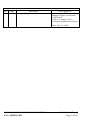
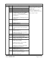
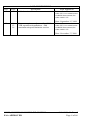
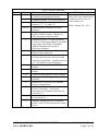
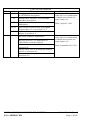
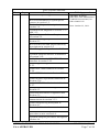
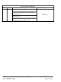
Rev A Page All LOG OF REVISIONS Description Complete Supplement FAA Approval Seyed-Joussef Hashemi Manager Flight Test Branch ANM-160L FAA, Los Angeles ACO Transport Airplane Directorate Date: July 15, 2008 AFMS, GARMIN G600 PFD/MFD SYSTEM FAA APPROVED 190-00601-01 Rev. J Page 2 of 46 Rev B Page 7 8 11 12 13 14 15 LOG OF REVISIONS Description Added GAD 43 to section 1.2 Added section 1.4 Added GAD 43 to diagram Added GAD 43 to diagram Added section 1.10 Changed GDU s/w to 3.01, AHRS s/w to 2.12, GNS 400W/500W software to 3.20, and added GAD 43 to section 2.2 Added section 2.5 Added section 2.6 Added section 2.10 Added section 2.13 19 Updated section 2.14 to account for SVT Added section 2.17 25 26 Date: July 17, 2009 Updated names of charting services in section 2.3 Expanded AHRS operational area in section 2.4 16 17 18 21 22 FAA Approval Seyed-Joussef Hashemi Manager Flight Test Branch ANM-160L FAA, Los Angeles ACO Transport Airplane Directorate Updated section 2.18 to account for VFR only installations Added item 4 in section 3.2 Updated section 3.3.1 to account for HSI track reversionary mode Added ‘check attitude’ and ‘AHRS Aligning’ alerts to table Updated section 3.6 to account for G600 internal TAWS Updated section 4.1 for new PFD knob mode annunciation 27 28 30 Added note pertinent to dual G600 installations in section 4.1 Added section 4.4 Added check boxes for FD with SVT and GAD 43 to section 4.5 Updated section 4.5.7 to explain FD behavior with SVT enabled Added section 4.5.8 AFMS, GARMIN G600 PFD/MFD SYSTEM FAA APPROVED 190-00601-01 Rev. J Page 3 of 46 LOG OF REVISIONS Rev C Page 16 Description Added section 2.8. FAA Approval Robert Grove ODA STC Unit Administrator GARMIN International, Inc ODA-240087-CE D 11 12 16 Remove requirement for standby ADI for VFR operations/installations. Add maximum airspeed limitation section. Date: September 15, 2009 Robert Grove ODA STC Unit Administrator GARMIN International, Inc ODA-240087-CE Date: November 17, 2009 AFMS, GARMIN G600 PFD/MFD SYSTEM FAA APPROVED 190-00601-01 Rev. J Page 4 of 46 Rev E Page All 7 9 10, 11 13 13 14 16 18 18 19 21 23 23 24 25 LOG OF REVISIONS Description Changed GPS/WAAS to GPS/SBAS. Corrected typographical errors. Updated section 1.1 for new features. Added new feature descriptions to sections 1.7, 1.8, and 1.9. Updated block diagrams for new features. Updated section 2.2 for applicability to this AFMS revision. Removed GPS navigator software table. Updated section 2.3 with limitation on use of helicopter databases and SD card usage with GSR 56 datalink. Added information on airport directory database. Updated section 2.8 to reflect current airspeed tape behavior. Updated sections 2.14, 2.15, and 2.16 to better describe the various terrain awareness functions. Updated section 2.17 for GFDS weather function. Corrected description of AHRS failure. Corrected description of heading failure. Corrected description of ADC failure. Corrected table entry for AHRS ALIGN. Added new section 4.4 for altitude alerter configuration. Added detail to section 4.6 regarding GAD 43 interface. Corrected description of autopilot interfaces in section 4.6.1. Corrected altitude alerter description in section 4.6.6. Added Caution and Note regarding GAD 43 AP TEST function in section 4.6.8. AFMS, GARMIN G600 PFD/MFD SYSTEM FAA APPROVED FAA Approval Robert Grove ODA STC Unit Administrator GARMIN International, Inc ODA-240087-CE Date: January 28, 2011 190-00601-01 Rev. J Page 5 of 46 Rev F Page All 10 14 20, 21 25 G All LOG OF REVISIONS Description Changed references to GNS navigators to GPS/SBAS navigators. Inserted new section 1.10 for HSDB interface description. Inserted new section 2.3 for moving map limitations. Moved rate-of-turn failure description from section 3.3.1 to section 3.3.2. Added checkbox for disabled altitude alerter in section 4.4. Re-issue complete supplement. Revised section 2.14 limitation on GPS/SBAS vertical coupling. Added attitude/air data interface to section 4.6. Added GDU 620 as an autopilot attitude source to section 4.6.1. Clarified dual autopilot interface in section 4.6.9. AFMS, GARMIN G600 PFD/MFD SYSTEM FAA APPROVED FAA Approval Robert Grove ODA STC Unit Administrator GARMIN International, Inc ODA-240087-CE Date: April 01, 2011 Robert Grove ODA STC Unit Administrator GARMIN International, Inc ODA-240087-CE Date: September 08, 2011 190-00601-01 Rev. J Page 6 of 46 Rev H Page All LOG OF REVISIONS Description Re-issue complete supplement. Revised information on system power sources in section 1.2. Revised audio panel description in section 1.6. Updated block diagrams in sections 1.11 and 1.12. Updated System Software Requirements in section 2.2. Revised Moving Map limitation in Section 2.3. Revised SafeTaxi and Airport Directory descriptions in section 2.4. Clarified applicability of section 2.11. FAA Approval Michael Warren ODA STC Unit Administrator GARMIN International, Inc ODA-240087-CE Date: October 25, 2012 Updated autopilot interface information in section 2.14. Added limitation for KFC 275/325 interface in section 2.22. Added Type Ratings limitation in section 2.23. Added ESI-1000 limitation in section 2.24. Added EFB limitation in Section 2.25. Added Surface Operations limitation in Section 2.26. Added MFD Video limitation in Section 2.27. Emergency Procedures reorganized into Section 3.1. Abnormal Procedures reorganized into Section 3.2. Added MISCOMP and NO AP DATA annunciations in section 3.3.2. Added airspeed bug description in Section 4.1. Removed Altitude Alerter section 4.4. Added electric standby attitude indicator procedure as new section 4.4. Updated autopilot procedures throughout section 4.6. AFMS, GARMIN G600 PFD/MFD SYSTEM FAA APPROVED 190-00601-01 Rev. J Page 7 of 46 Rev J Page All LOG OF REVISIONS Description FAA Approval Re-issue complete supplement. Corrected navigation radio information in Section 1.1. Corrected Auto Slew description in Section 2.12. Updated Bendix/King Altitude Preselect functionality in Section 4.6.6.3. AFMS, GARMIN G600 PFD/MFD SYSTEM FAA APPROVED See Page 1 190-00601-01 Rev. J Page 8 of 46 TABLE OF CONTENTS SECTION 1. GENERAL ................................................................................. 11 1.1 1.2 1.3 1.4 1.5 1.6 1.7 1.8 1.9 1.10 1.11 1.12 1.13 G600 PRIMARY FLIGHT / MULTI-FUNCTION DISPLAY SYSTEM ........... 11 SYSTEM POWER SOURCES .................................................................. 12 NAVIGATION SOURCES ....................................................................... 12 SYNTHETIC VISION TECHNOLOGY....................................................... 13 AUTOPILOT INTERFACE ....................................................................... 14 AUDIO PANEL ..................................................................................... 14 TRAFFIC AND WEATHER SYSTEMS ...................................................... 14 VIDEO SOURCES .................................................................................. 15 RADAR ALTIMETER............................................................................. 15 HIGH SPEED DATA BUS INTERFACE .................................................... 15 SINGLE G600 OPERATIONAL BLOCK DIAGRAM .................................. 16 DUAL G600 OPERATIONAL BLOCK DIAGRAM ..................................... 17 DEFINITIONS ....................................................................................... 18 SECTION 2. LIMITATIONS ......................................................................... 19 2.1 2.2 2.3 2.4 2.5 2.6 2.7 2.8 2.9 2.10 2.11 2.12 2.13 2.14 2.15 2.16 2.17 2.18 2.19 2.20 2.21 2.22 2.23 2.24 2.25 2.26 2.27 COCKPIT REFERENCE & PILOT’S GUIDE .............................................. 19 SYSTEM SOFTWARE REQUIREMENTS .................................................. 19 MOVING MAP ..................................................................................... 19 DATABASE CARDS .............................................................................. 19 AHRS OPERATIONAL AREA................................................................ 20 MAGNETIC VARIATION OPERATIONAL AREA ...................................... 20 NAVIGATION ANGLE ........................................................................... 21 AHRS NORMAL OPERATING MODE .................................................... 21 AIRSPEED LIMITATIONS AND INDICATOR MARKINGS .......................... 21 AEROBATIC MANEUVERS ................................................................... 21 ELECTRIC STANDBY ATTITUDE GYRO ................................................ 21 COURSE POINTER AUTO SLEWING ...................................................... 22 SYNTHETIC VISION TECHNOLOGY....................................................... 22 AUTOPILOT INTERFACE ....................................................................... 22 TERRAIN PROXIMITY FUNCTION ......................................................... 23 TAWS FUNCTION [GDU 620 UNITS WITH INTERNAL TAWS] ............ 23 TAWS ANNUNCIATIONS ON THE PFD [FROM A GARMIN NAVIGATOR] 23 DATALINKED WEATHER DISPLAY (XM OR GFDS WEATHER)............. 24 TRAFFIC DISPLAY ............................................................................... 24 ACTIVE WEATHER RADAR................................................................ 24 KINDS OF OPERATIONS ....................................................................... 25 KFC 275/325 ALTITUDE PRESELECT .................................................. 25 TYPE RATINGS .................................................................................... 25 L-3 ESI-1000 ELECTRONIC STANDBY INSTRUMENT ........................... 26 ELECTRONIC FLIGHT BAG (EFB) APPLICATIONS ................................. 26 SURFACE OPERATIONS........................................................................ 26 MFD VIDEO DISPLAY ......................................................................... 26 AFMS, GARMIN G600 PFD/MFD SYSTEM FAA APPROVED 190-00601-01 Rev. J Page 9 of 46 SECTION 3. EMERGENCY PROCEDURES .............................................. 27 3.1 3.2 3.3 EMERGENCY PROCEDURES ................................................................. 27 ABNORMAL PROCEDURES ................................................................... 31 WARNINGS, CAUTIONS, AND ADVISORIES ........................................... 34 SECTION 4. NORMAL PROCEDURES ...................................................... 37 4.1 4.2 4.3 4.4 4.5 4.6 PFD KNOB & PFD SOFT KEYS ........................................................... 37 MFD KNOBS & MFD SOFT KEYS ....................................................... 37 ALTITUDE SYNCHRONIZATION ............................................................ 38 ELECTRIC STANDBY ATTITUDE GYRO ................................................. 38 SYNTHETIC VISION TECHNOLOGY ....................................................... 38 AUTOPILOT OPERATIONS WITH THE G600 SYSTEM ............................. 39 SECTION 5. PERFORMANCE ..................................................................... 46 SECTION 6. WEIGHT AND BALANCE ...................................................... 46 SECTION 7. SYSTEM DESCRIPTIONS ...................................................... 46 AFMS, GARMIN G600 PFD/MFD SYSTEM FAA APPROVED 190-00601-01 Rev. J Page 10 of 46 Section 1. GENERAL 1.1 G600 Primary Flight / Multi-Function Display System The G600 PFD/MFD System consists of a Primary Flight Display (PFD) and Multi-Function Display (MFD) housed in a single Garmin Display Unit (GDU), plus an Air Data Computer (ADC) and Attitude and Heading Reference System (AHRS). The G600 interfaces with other installed systems in the aircraft, including Garmin GPS/SBAS navigators, VHF navigation radios, Garmin GDL 69 data link radios, Garmin GSR 56 Iridium transceivers, various weather radars, audio panels, video sources, radar altimeters, traffic systems and ADF navigators. The primary function of the PFD is to provide attitude, heading, air data and navigation information to the pilot. The primary function of the MFD is to provide mapping, terrain, and flight plan information. The standby instruments (altimeter, airspeed, attitude, and magnetic compass) are completely independent from the PFD and will continue to operate in the event the PFD is not usable. These standby instruments should be included in the pilot’s normal instrument scan and may be referenced if the PFD data is in question. A second G600 system installed on the co-pilot’s side does not require additional standby instruments. AFMS, GARMIN G600 PFD/MFD SYSTEM FAA APPROVED 190-00601-01 Rev. J Page 11 of 46 1.2 System Power Sources The G600 system depends on electrical power to maintain proper operation. The Garmin Display Unit (GDU), Attitude and Heading Reference System (AHRS), and Air Data Computer (ADC) are directly tied to the aircraft’s main or essential bus and energized when the aircraft master switch is turned on. Other systems, like the navigation equipment, weather datalink, autopilot and Adapter (GAD) are typically located on the avionics bus and may not be operable during engine start. The major components of the G600 are circuit breaker protected with resettable type breakers available to the pilot. These breakers are located at the main or essential bus circuit breaker panel and labeled as follows: 1. 2. 3. 4. 5. PFD - Garmin Display Unit (PFD/MFD), GDU 620 AHRS - Attitude and Heading Reference System, GRS 77 ADC - Air Data Computer, GDC 74A/B GAD - Garmin Adapter, GAD 43/43e STBY ATT- Electric Standby Attitude Indicator In dual installations the pilot side equipment is suffixed with the number 1 and the copilot side equipment is suffixed with the number 2. For example: PFD 1 and PFD 2. Equipment that receives power from two different circuit breakers will be suffixed with the letters A and B. For example: PFD 1A and PFD 1B, or PFD 2A and PFD 2B. 1.3 Navigation Sources The G600 requires at least one Garmin GPS/SBAS navigation unit to ensure the integrity of the Attitude and Heading Reference System. The AHRS will still operate in a reversionary mode if the GPS fails, and the PFD attitude display will still be presented, see Paragraph 2.8. The G600 HSI can be selected to display course deviation information from up to four independent sources: two GPS, and two VHF NAV. In addition, the HSI can display two simultaneous bearing pointers sourced from GPS, VHF NAV, or ADF. AFMS, GARMIN G600 PFD/MFD SYSTEM FAA APPROVED 190-00601-01 Rev. J Page 12 of 46 1.4 Synthetic Vision Technology SVT uses an internal terrain database and GPS location to present the pilot with a synthetic view of the terrain in front of the aircraft. The purpose of the SVT system is to assist the pilot in maintaining situational awareness with regard to the terrain and traffic surrounding the aircraft. A typical SVT display is shown below: SVT provides additional features on the G600 primary flight display (PFD) which display the following information: Synthetic Terrain; an artificial, database derived, three dimensional view of the terrain ahead of the aircraft within a field of view of approximately 25 degrees left and 25 degrees right of the aircraft heading. Obstacles; obstacles such as towers, including buildings over 200 AGL that are within the depicted synthetic terrain field of view. AFMS, GARMIN G600 PFD/MFD SYSTEM FAA APPROVED 190-00601-01 Rev. J Page 13 of 46 Flight Path Marker (FPM); an indication of the current lateral and vertical path of the aircraft. The FPM is always displayed when synthetic terrain is selected for display. Traffic; a display on the PFD indicating the position of other aircraft detected by a traffic system interfaced to the G600 system. Horizon Line; a white line indicating the true horizon is always displayed on the SVT display. Horizon Heading; a pilot selectable display of heading marks displayed just above the horizon line on the PFD. Airport Signs; pilot selectable “signposts” displayed on the synthetic terrain display indicating the position of nearby airports that are in the G600 database. Runway Highlight; a highlighted presentation of the location and orientation of the runway(s) at the destination airport. The synthetic terrain depiction displays an area approximating the view from the pilot’s eye position when looking directly ahead out the windshield in front of the pilot. Terrain features outside this field of view are not shown on the display. The synthetic terrain display is intended to aid the pilot awareness of the terrain and obstacles in front of the airplane. It may not provide either the accuracy or fidelity, or both, on which to solely base decisions and plan maneuvers to avoid terrain or obstacles. The synthetic vision elements are not intended to be used for primary aircraft control in place of the primary flight instruments. 1.5 Autopilot Interface The G600 may be interfaced to an optional autopilot. The G600 typically provides course and heading datum to the autopilot based on the data selected for display on the HSI. For multiple GPS/NAV systems, the G600 acts as a selection hub for the autopilot’s NAV mode, and the G600 may also provide GPS Steering data. Some autopilots may provide Flight Director capabilities which can be displayed on the G600 Attitude Indicator as a Single Cue Flight Director. 1.6 Audio Panel The G600 PFD/MFD system may be interfaced to the aircraft audio panel to provide aural alerting generated by the G600 (required for TAWS-B installations). 1.7 Traffic and Weather Systems The G600 PFD/MFD system supports TIS traffic via the Garmin GTX Series Mode-S Transponders. The system also supports TAS/TCAS/TIS traffic from various active traffic awareness systems. The information from these systems is available and controllable on the MFD. AFMS, GARMIN G600 PFD/MFD SYSTEM FAA APPROVED 190-00601-01 Rev. J Page 14 of 46 The G600 PFD/MFD system supports XM datalink weather via the Garmin GDL69 and GDL69A receivers. If an optional XM datalink receiver is installed, the pilot will be able to access graphical and text weather products on the MFD and control the audio entertainment data from the MFD while listening via an appropriately installed audio panel. Datalink weather is also available via the Garmin GSR 56 Iridium Transceiver. The control and display of Iridium satellite weather on the MFD is similar to XM weather. Control and display of various airborne weather radars is optionally available on the MFD. The G600 supports Garmin GWX weather radar, as well as certain 3rd-party weather radars. 1.8 Video sources The G600 Avionics Display System can display images from up to 2 video inputs. Video images are displayed on the MFD. The G600 does not provide a means to control the video source; however the digital images from the video source can be adjusted using the G600. 1.9 Radar Altimeter The G600 supports the display of radar altitude on the PFD from supported radar altimeters. 1.10 High Speed Data Bus Interface Some Garmin equipment connected to the G600 system utilizes the High Speed Data Bus (HSDB) interface. HSDB is similar to an Ethernet bus and provides a high-speed interface between Garmin avionics. Like Ethernet, data between two units may be passed through intermediate “hub” units. Interfaced equipment that uses HSDB includes the GTN 6XX/7XX navigators, GDL 69 datalink receiver, GWX 68, and GTS 8XX traffic systems. The HSDB interfaces are installed to so that maximum data path redundancy is achieved. However, depending on the number of HSDB units installed, failure of one HSDB unit may result in loss of data on the G600 from “downstream” HSDB units. Any loss of data will be annunciated on the G600. AFMS, GARMIN G600 PFD/MFD SYSTEM FAA APPROVED 190-00601-01 Rev. J Page 15 of 46 1.11 Single G600 Operational Block Diagram Equipment Installed per this STC Adapter (optional) GAD 43/43e Aircraft Systems Magnetometer GMU 44 AHRS GRS 77 PFD/MFD Display GDU 620 Electric Standby Attitude*** (optional) Air Data Computer GDC 74() Temperature Probe GTP 59 Audio Panel (optional)** No. 1 GPS/SBAS Navigator (required) Traffic (optional) No. 2 GPS/SBAS Navigator (optional) XM WX/Entertainment GDL 69/69A (optional) No. 1 VOR/Localizer/GS (optional) Weather Radar (optional) No. 2 VOR/Localizer/GS Radar Altimeter (optional) (optional) Iridium Data Link Autopilot/Flight Director (optional) (optional) Video Source (optional) ADF (optional) Existing Equipment (already installed in aircraft) Standby Airspeed Standby Attitude* Standby Altimeter Magnetic Compass (required) AFMS, GARMIN G600 PFD/MFD SYSTEM FAA APPROVED *Standby Attitude: may be replaced with electric attitude indicator with integral / dedicated backup battery. **Audio panel connection to GDU 620 is recommended for tones and aural alerts generated by the GDU 620. This MUST be connected if TAWS and/or SVT is enabled. *** Installation of the Mid-Continent electric standby attitude indicator is approved by this STC. 190-00601-01 Rev. J Page 16 of 46 (required) Copilot PFD/MFD Display GDU 620 Equipment Installed per this STC AFMS, GARMIN G600 PFD/MFD SYSTEM FAA APPROVED Magnetic Compass Standby Altimeter (required on pilot side only) Standby Attitude* Standby Airspeed (optional)** Video Source Audio Panel Various Models (optional)*** Temperature Probe GTP 59 #1 Air Data Computer GDC 74() #1 (optional) (optional)** Iridium Data Link Radar Altimeter (optional)** Weather Radar XM WX/Entertainment GDL 69/69A (optional) (optional)** Autopilot/Flight Director (optional)** Traffic (optional)** ADF (optional)** No. 2 VOR/Localizer/GS (optional)** No. 1 VOR/Localizer/GS (required) No. 2 GPS/SBAS Navigator No. 1 GPS/SBAS Navigator Flight Director Only **** Installation of the Mid-Continent electric standby attitude indicator is approved by this STC. ***Audio Panel connection to GDU 620 is recommended for tones and aural alerts generated by the GDU 620. This MUST be connected if TAWS and/or SVT is enabled. of optional equipment to both GDUs is not required. Functions provided by the optional equipment will only be available on the GDU to which the optional equipment is connected. **Optional Equipment: Connection *Standby Attitude: May be replaced with electric attitude indicator with integral /dedicated backup battery. (already installed in aircraft) Existing Equipment (optional)** Video Source Temperature Probe GTP 59 #2 Air Data Computer GDC 74() #2 AHRS GRS 77 #2 Pilot PFD/MFD Display GDU 620 (optional) AHRS GRS 77 #1 Electric Standby Attitude*** Magnetometer GMU 44 #2 Aircraft Systems Magnetometer GMU 44 #1 Adapter (optional) GAD 43/43e 1.12 Dual G600 Operational Block Diagram 190-00601-01 Rev. J Page 17 of 46 1.13 Definitions The following terminology is used within this document: ADC: Air Data Computer ADF: Automatic Direction Finder AHRS: Attitude & Heading Reference System AUX: Auxiliary BARO: Barometric Pressure BRG: Bearing CDI: Course Deviation Indicator CRS: Course FD: Flight Director FPM: Flight Path Marker GDU: Garmin Display Unit GPS: Global Positioning System GPSS: GPS Roll Steering HDG: Heading HSI: Horizontal Situation Indicator IFR: Instrument Flight Rules IMC: Instrument Meteorological Conditions LOI: Loss of Integrity MFD: Multi Function Display PFD: Primary Flight Display SBAS: Space-based Augmentation System SD: Secure Digital SVT: Synthetic Vision Technology TAS: Traffic Awareness System TAWS: Terrain Awareness and Warning System (a TSO-C151b function) TCAS: Traffic Collision and Avoidance System TIS: Traffic Information Service VFR: Visual Flight Rules VMC: Visual Meteorological Conditions V/S: Vertical Speed AFMS, GARMIN G600 PFD/MFD SYSTEM FAA APPROVED 190-00601-01 Rev. J Page 18 of 46 Section 2. LIMITATIONS 2.1 Cockpit Reference & Pilot’s Guide The Garmin G600 Cockpit Reference Guide P/N 190-00601-03, Revision A or later appropriate revision must be immediately available to the flight crew. Garmin also provides a detailed G600 Pilot’s Guide P/N 190-00601-02. This reference material is not required to be on board the aircraft but does contain a more in depth description of all the functions and capabilities of the G600. 2.2 System Software Requirements The G600 must utilize the following or later FAA approved software versions for this AFMS revision to be applicable: Component GDU 620 GRS 77 Identification PFD/MFD AHRS Software Version 6.11 3.03 2.3 Moving Map The moving map on the MFD is advisory in nature and is not approved for course guidance. The moving map on the MFD must be cross checked for correctness against the PFD HSI, published charts, or other approved sources of navigation information. 2.4 Database Cards Databases identified as intended for helicopter use must not be used. These databases may be identified by the word “HELI” or “HELICOPTER” in their title. The G600 utilizes several databases. Database titles display in yellow if expired or in question (Note: the G600 receives the calendar date from the GPS, but only after acquiring a position fix). Database cycle information is displayed at power up on the MFD screen, but more detailed information is available on the AUX pages. Internal database validation prevents incorrect data from being displayed. The upper Secure Digital (SD) data card slot is typically vacant as it is used for software maintenance and navigational database updates. The lower data card slot should contain a data card with the system’s terrain / obstacle information and optional data including Safe Taxi, FliteCharts and ChartView electronic charts. CAUTION When interfaced with a GSR56 Iridium transceiver only one SD card may be present in the GDU620 and it must be in the lower slot. AFMS, GARMIN G600 PFD/MFD SYSTEM FAA APPROVED 190-00601-01 Rev. J Page 19 of 46 The terrain databases are updated periodically and have no expiration date. Coverage of the terrain database is between North 75° latitude and South 60° latitude in all longitudes. Coverage of the airport terrain database is worldwide. The obstacle database contains data for obstacles, such as towers, that pose a potential hazard to aircraft. Obstacles 200 feet and higher are included in the obstacle database. It is very important to note that not all obstacles are necessarily charted and therefore may not be contained in the obstacle database. Coverage of the obstacle database includes the United States and Europe. This database is updated on a 56-day cycle. The Garmin SafeTaxi database contains airport diagrams for selected airports. This database is updated on a 56-day cycle. The Garmin FliteCharts database contains procedure charts for the coverage area purchased. This database is updated on a 28-day cycle. If not updated within 180 days of the expiration date, FliteCharts will no longer function. The Jeppesen ChartView electronic charts database contains procedure charts for the coverage area purchased. An own-ship position icon will be displayed on these charts. This database is updated on a 14-day cycle. If not updated within 70 days of the expiration date, ChartView will no longer function. The airport directory database contains information on landing facilities, such as operating hours, services available, and transportation/lodging resources. Airport directory information may be available from multiple sources and coverage areas. This database is updated on a 56-day cycle. 2.5 AHRS Operational Area The AHRS used in the G600 is limited in its operational area: IFR Operations are prohibited north of 72N and south of 70S latitudes. In addition, IFR operations are prohibited in the following four regions: 1) North of 65° North latitude between longitude 75° W and 120° W 2) North of 70° North latitude between longitude 70° W and 128° W 3) North of 70° North latitude between longitude 85° E and 114° E 4) South of 55° South latitude between longitude 120° E and 165° E Loss of the G600 heading and attitude may occur near the poles, but this will not affect the GPS track or standby attitude indicator. 2.6 Magnetic Variation Operational Area IFR operations are prohibited in areas where the magnetic variation is greater than 99.9 degrees East or West. AFMS, GARMIN G600 PFD/MFD SYSTEM FAA APPROVED 190-00601-01 Rev. J Page 20 of 46 2.7 Navigation Angle The GDU 620 Navigation Angle can be set to either True or Magnetic on the AUX page. The Navigation Angle defines whether the GDU 620 headings are referenced to True or Magnetic North. The Navigation Angle set in the GDU 620 must match that which is set on all GPS/SBAS navigators interfaced to the unit. 2.8 AHRS Normal Operating Mode The Attitude and Heading Reference System integrity monitoring features require the availability of GPS and Air Data. Although the attitude will remain valid if one of these systems becomes inoperative, IFR flight is not authorized unless both integrity systems are fully operational. The G600 monitors these integrity systems automatically and will alert the pilot when the AHRS is not receiving GPS or Air Data. Note: In dual GPS installations, only one GPS needs to be available for IFR use. 2.9 Airspeed Limitations and Indicator Markings The original type design approved airspeed limitations remain in effect. The airspeed limitations imposed by the AFM/POH, standby airspeed indicator and/or airspeed limitation placards must be observed. The G600 airspeed tape displays red/white striping to indicate the maximum allowable airspeed (VNE/VMO/MMO). This maximum allowable airspeed display is configured to indicate the appropriate maximum allowable airspeed for the airplane, including variations for altitude or Mach number. The G600 airspeed tape displays a red low-speed awareness band at the lower range of the airspeed tape. This low-speed awareness band is configured to a fixed value. It does not indicate an actual or calculated stall speed and does not adjust with variations in aircraft weight or other factors. All other G600 airspeed tape indications are configured to indicate the original type design limitations. The G600 airspeed tape does not adjust these additional markings (including VNO, landing gear, or flap speed limitations) for variations with aircraft weight, altitude, or other factors. 2.10 Aerobatic Maneuvers Conducting aerobatic maneuvers may cause the attitude information displayed on the G600 to be incorrect or temporarily removed from the display. 2.11 Electric Standby Attitude Gyro If an electric standby attitude gyro is installed, the gyro operates form the aircraft electrical system with a dedicated emergency battery specific to the electric gyro. The electric attitude gyro battery capacity may vary considerably depending on temperature, charge status, and battery life condition. Low temperatures below 32°F will temporarily degrade battery capacity. Internal chemistry will slowly degrade battery capacity over several years of operation even when correctly AFMS, GARMIN G600 PFD/MFD SYSTEM FAA APPROVED 190-00601-01 Rev. J Page 21 of 46 maintained. A poorly maintained battery will suffer accelerated degradation. Extended storage in a discharged state and over-charging will permanently damage the battery. Complete charging is required to bring the battery up to full capacity if it has been unused for more than four months or partially discharged. 2.12 Course Pointer Auto Slewing The G600 HSI will auto slew, i.e. automatically rotate the GPS course pointer to the desired course defined by each GPS leg. The system will also auto slew the VHF NAV course pointer when the CDI transitions to a LOC setting if an ILS, LOC, LOC BC, LDA, or SDF approach is loaded in the GPS/SBAS navigator. The VHF NAV (green) course pointer will only auto slew if the approach is loaded in the navigator, a LOC frequency is loaded in the active NAV frequency, and then the HSI source is changed to the corresponding VHF NAV for the approach. Back Course approaches will auto slew to the reciprocal course. The system is not capable of automatically setting the inbound VHF NAV course pointer if an approach is not loaded in the GPS/SBAS Navigation System. The pilot should always double check the inbound course pointer prior to initiating any transition on any VHF NAV approach. Auto slewing the VHF NAV course pointer to the correct selected course is a database dependent function. 2.13 Synthetic Vision Technology The use of the synthetic vision display elements alone for aircraft control without reference to the G600 primary flight instruments or the aircraft standby instruments is prohibited. The use of the synthetic vision display alone for navigation, or obstacle, terrain, or traffic avoidance is prohibited. 2.14 Autopilot Interface The G600 acts as a navigation source switching hub to an interfaced autopilot when multiple navigation sources are available. The autopilot will only couple to the heading, navigation, altitude, and vertical speed selections on PFD 1. Some autopilots may have navigation source selection integral to their system; this feature is overridden by the G600 navigation source selection described herein. Changing the navigation sources displayed on the HSI (by pressing the CDI button or the 1-2 button) may result in some autopilots disconnecting or entering a wings level mode. The autopilot will not couple to the pre-selected altitude or vertical speed if not properly configured or supported by the installation. Refer to the autopilot operator’s manual or Airplane Flight Manual Supplement for the proper operation of that system. AFMS, GARMIN G600 PFD/MFD SYSTEM FAA APPROVED 190-00601-01 Rev. J Page 22 of 46 Not all autopilot systems are approved for GPS vertical coupling; therefore consult the AFMS for the GPS/SBAS system and/or the autopilot system. Flight director commands on PFD 2 are repeated from PFD 1. When utilizing the flight director display on PFD 2, ensure that the CDI source and BARO settings on PFD 2 match those on PFD 1. For installations where the GAD 43 provides attitude information to the autopilot, the GAD 43 autopilot disconnect mechanism must be tested and operational before flight using the autopilot. Refer to Section 4.6.9. 2.15 Terrain Proximity Function The G600 terrain configuration is indicated on the dedicated terrain page of the MAP group. “TERRAIN PROXIMITY” will be displayed as the page title if this function is configured. The G600 terrain and obstacle information appears on the MFD display as red and yellow tiles or towers, and is depicted for advisory only. Aircraft maneuvers and navigation must not be predicated upon the use of the terrain display. Terrain unit alerts are advisory only and are not equivalent to warnings provided by TAWS. 2.16 TAWS Function [GDU 620 Units with internal TAWS] The G600 system optionally contains Class B TAWS, a TSO-C151b certified function. The G600 terrain configuration is indicated on the dedicated terrain page of the MAP group. “TAWS-B” will be displayed as the page title if this function is configured. Pilots are authorized to deviate from their current ATC clearance to the extent necessary to comply with TAWS warnings. Navigation must not be predicated upon the use of TAWS. To avoid unwanted alerts, TAWS should be inhibited when landing at an airport that is not included in the airport database. In Dual G600 installations, TAWS audio is only provided by the Pilot side GDU. If the Pilot side GDU TAWS becomes inoperative, the Co-Pilot side GDU TAWS visual annunciations may still function, but the aural TAWS alerts will not be heard. 2.17 TAWS Annunciations on the PFD [from a Garmin navigator] The G600 will display TAWS (Terrain Awareness and Warning System) annunciations on the PFD if the G600 is interfaced to a Garmin navigator with integrated TAWS on GPS 1. The required TAWS annunciations appear in the upper right of the PFD. These annunciations include PULL UP (red), TERRAIN (yellow), TER N/A (yellow), TER INHB (white). These annunciations are not relative to the terrain displayed on the MFD or the yellow/red terrain shading of the Synthetic Vision displayed on the PFD of the G600 system. Refer to the Garmin navigator Airplane Flight Manual Supplement for proper pilot action and information on these alerts. AFMS, GARMIN G600 PFD/MFD SYSTEM FAA APPROVED 190-00601-01 Rev. J Page 23 of 46 TAWS alerts on the PFD of the G600 System are only displayed from the GPS/TAWS navigator interfaced as GPS 1 and are displayed regardless of the system 1-2 setting, which drives all other PFD and MFD data used by the G600. 2.18 Datalinked Weather Display (XM or GFDS weather) Datalink weather data is provided by an optional GDL 69 (XM) or GSR 56 (GFDS) interface. The weather information display on the MFD of the G600 is limited to supplemental use only and may not be used in lieu of an official weather data source. Use of the datalink weather display for hazardous weather (e.g thunderstorm) penetration is prohibited. The datalink weather display is intended for use as an aid to situational awareness only. 2.19 Traffic Display Traffic may be displayed on the G600 System when connected to an approved optional TCAS, TAS, or TIS traffic device. These systems are capable of providing traffic monitoring and alerting to the pilot. Traffic shown on the display may or may not have traffic alerting available. The display of traffic is an aid to visual acquisition and may not be utilized for aircraft maneuvering. 2.20 Active Weather RADAR RADAR is broadcasting energy while in Weather or Ground mapping modes. If the G600 system is configured to control an airborne weather radar unit, observe all safety precautions, including: Do not operate in the vicinity of refueling operations. Do not operate while personnel are in the vicinity (approximately 20 feet) of the radar sweep area. WARNING If a radar system is installed, it generates microwave radiation and improper use, or exposure, may cause serious bodily injury. DO NOT OPERATE THE RADAR EQUIPMENT UNTIL YOU HAVE READ AND CAREFULLY FOLLOWED THE SAFETY PRECAUTIONS AND INSTRUCTIONS in the USER MANUAL. AFMS, GARMIN G600 PFD/MFD SYSTEM FAA APPROVED 190-00601-01 Rev. J Page 24 of 46 2.21 Kinds of Operations Unless placarded as limited to VFR only operations, G600 equipment installed in an appropriately certified aircraft is approved for Day and Night / VFR and IFR operations in accordance with 14 Code of Federal Regulations Part 91, Part 121, and Part 135 when appropriately maintained. The table below lists the minimum fully functional G600 System Elements** required for IFR flight operations: Equipment Primary/Multi Flight Display Garmin GPS/SBAS Navigator Attitude / Heading Unit (AHRS) Air data computer (ADC) Magnetometer (GMU) Standby Attitude Indicator Standby Airspeed Indicator Standby Altimeter Magnetic Compass Number installed 1 or 2 1 or 2 1 or 2 1 or 2 1 or 2 1 1 1 1 VFR IFR 1a* 1a* 1b 1b 1 1 1 1 1 1 1 1 1 1 * For VFR operations under 14 CFR Part 91, the aircraft must have one source of altitude and airspeed information. This may be from either the PFD or the standby instruments. (i.e. all “1a” items or all “1b” items from the table above) ** For IFR flight a fully functional G600 system should not generate system alerts, which indicate faults within the system or any interfaced equipment. 2.22 KFC 275/325 Altitude Preselect When the altitude preselect option is installed with KFC 275/325 autopilots, SOFT RIDE (SR) mode must be disengaged during altitude capture mode (ALTC). The following placard must be installed near the autopilot mode controller or above PFD 1: “DISENGAGE SOFT RIDE DURING ALTITUDE CAPTURE (ALTC)” 2.23 Type Ratings Unless otherwise authorized by this section, operations are prohibited in aircraft that require a type rating under 14 CFR 61.31(a). AFMS, GARMIN G600 PFD/MFD SYSTEM FAA APPROVED 190-00601-01 Rev. J Page 25 of 46 2.24 L-3 ESI-1000 Electronic Standby Instrument The independent power source for the L-3 ESI-1000 must be verified to be operational before flight, or the ESI-1000 must be considered inoperative. For the verification procedure, refer to the approved Airplane Flight Manual and/or Instructions for Continued Airworthiness for the independent power source. 2.25 Electronic Flight Bag (EFB) Applications Class 3 EFB applications have not been evaluated as part of this STC. Use of the system for EFB applications (such as the moving map or electronic charts) may require additional evaluation or operational approval. 2.26 Surface Operations Do not use SafeTaxi or Chartview functions as the basis for ground maneuvering. SafeTaxi and Chartview functions do not comply with the requirements of AC 20-159 and are not qualified to be used as an airport moving map display (AMMD). SafeTaxi and Chartview are to be used by the flight crew to orient themselves on the airport surface to improve flight crew situational awareness during ground operations. 2.27 MFD Video Display Video images displayed on the MFD are intended for use as an aid to situational awareness only. Aircraft maneuvering based solely on the MFD video display is prohibited. AFMS, GARMIN G600 PFD/MFD SYSTEM FAA APPROVED 190-00601-01 Rev. J Page 26 of 46 Section 3. EMERGENCY PROCEDURES 3.1 Emergency Procedures 3.1.1 PFD 1 Failure PFD 1 failure is indicated by the loss of displayed information on the PFD, including blank, frozen, or unresponsive display. 1. 2. Use standby flight instruments for attitude, airspeed, altitude, and heading reference. Refer directly to navigation source for navigation information (such as GPS). If autopilot is engaged: 3. Verify autopilot mode and cross check against standby flight and navigation data. 3.1.2 AHRS Failure Attitude and Heading Reference System (AHRS) failure is indicated by removal of the sky/ground presentation, a red X, and a yellow “ATTITUDE FAIL” on the PFD. Rate-of-turn information (heading trend vector) will not be available. A heading failure will also occur as described in Section 3.2.1. 1. 2. Use Standby Attitude Indicator. Seek VFR conditions or land as soon as practical. AFMS, GARMIN G600 PFD/MFD SYSTEM FAA APPROVED 190-00601-01 Rev. J Page 27 of 46 3.1.3 Air Data Computer (ADC) Failure Air Data Computer failure is indicated by a red X and yellow text over the airspeed, altimeter, vertical speed, TAS and OAT displays. Some derived functions, such as true airspeed and wind calculations will also be lost. If valid GPS data is available, the PFD will automatically revert to display GPS calculated altitude relative to mean sea level. This GPS altitude is displayed above the altitude tape. 1. 2. Use Standby Airspeed Indicator and Altimeter Seek VFR conditions or land as soon as practical If ADC 1 has failed and PFD 1 AIR DATA switch is installed: 3. PFD 1 AIR DATA switch – Select ADC 2 NOTE ALT NO COMP and IAS NO COMP alerts will be present. 3.1.4 Loss of Electrical Power In the event of a total loss of electrical power, the G600 system will cease to operate and the pilot must utilize the standby instruments to fly the aircraft. 3.1.5 Loss of Electrical Power to 3-inch Electric Standby Attitude Indicator (flashing amber STBY PWR light) When a 3-inch electric standby attitude indicator is installed, loss of primary electrical power to the attitude indicator is annunciated by a flashing amber light on the indicator. The attitude indicator is operating on backup battery power, and pilot action is required for the gyro to continue operating. 1. 2. 3. 4. Press STBY PWR button on the indicator one time. Verify that the flashing amber light extinguishes. Verify that the red gyro warning flag is not displayed. Seek visual meteorological conditions (VMC) or land as soon as practical (operation of standby attitude indicator is limited by battery life). WARNING Do not press the STBY PWR button a second time after the flashing amber light extinguishes. This will turn off the backup battery and the red gyro warning flag will be displayed. If the STBY PWR button is inadvertently pressed and the red gyro warning flag is displayed, press the STBY PWR button again to return to battery power operation (red gyro warning flag should not be displayed). AFMS, GARMIN G600 PFD/MFD SYSTEM FAA APPROVED 190-00601-01 Rev. J Page 28 of 46 3.1.6 Loss of Electrical Power to 2-inch Electric Standby Attitude Indicator (flashing or steady amber STBY text) When a 2-inch electric standby attitude indicator is installed, loss of primary electrical power to the attitude indicator is annunciated by amber STBY text on the Annunciation Control Unit. The attitude indicator is operating on backup battery power, and pilot action may be required for the gyro to continue operating. If the amber STBY text is flashing (manual operation): 1. Press the STBY PWR button one time. 2. Verify that the amber STBY text is steadily illuminated. 3. Verify that the red gyro warning flag is not displayed. 4. Seek visual meteorological conditions (VMC) or land as soon as practical (operation of standby attitude indicator is limited by battery life). If the amber STBY text is steadily illuminated (automatic operation): 1. Verify that the red gyro warning flag is not displayed. 2. Seek visual meteorological conditions (VMC) or land as soon as practical (operation of standby attitude indicator is limited by battery life). WARNING Do not press the STBY PWR when the amber STBY text is steadily illuminated. This will turn off the backup battery and the red gyro warning flag will be displayed. If the STBY PWR button is inadvertently pressed and the red gyro warning flag is displayed, press the STBY PWR button again to return to battery power operation (red gyro warning flag should not be displayed). AFMS, GARMIN G600 PFD/MFD SYSTEM FAA APPROVED 190-00601-01 Rev. J Page 29 of 46 3.1.7 TAWS WARNING Red annunciator on PFD and aural “PULL UP”: 1. 2. Disconnect Autopilot. Initiate maximum power climb at best angle of climb airspeed (V X). After warning ceases: 3. 4. 5. Set maximum continuous power. Climb and maintain safe altitude. Advise ATC of altitude deviation, if appropriate. NOTE Only vertical maneuvers are recommended, unless either operating in visual meteorological conditions (VMC), or the flight crew determines, based on all available information, that turning in addition to the vertical escape maneuver is the safest course of action, or both. AFMS, GARMIN G600 PFD/MFD SYSTEM FAA APPROVED 190-00601-01 Rev. J Page 30 of 46 3.2 Abnormal Procedures 3.2.1 Heading Failure Heading failure is indicated by replacement of the digital heading display with amber “HDG” text and a red X. If valid GPS ground track is available, it will automatically be displayed in place of heading. The HSI heading bug and course pointer will continue to function normally, using GPS ground track as a reference instead of magnetic heading. If GPS track is not available: 1. 2. Use standby compass for heading reference. Verify selected course using “CRS” button and PFD knob. CAUTION No directional references will be displayed on HSI. The heading bug will be removed, and the course pointer will remain fixed at the top of the HSI regardless of aircraft heading. Course deviation indications will behave similar to a traditional CDI. VOR deviations will be relative the selected course with a TO/FROM indication. Localizer deviations will not be affected by the selected course, and reverse sensing will occur when tracking inbound on a localizer back course. AFMS, GARMIN G600 PFD/MFD SYSTEM FAA APPROVED 190-00601-01 Rev. J Page 31 of 46 3.2.2 GPS Data Failure GPS data failure may be indicated by any or all of following: Loss of GPS course deviation information on HSI Amber “LOI” text on the HSI Amber “NO GPS POSITION” text on the MFD moving map Loss of waypoint bearing or distance information 1. Select alternate GPS source, if available, by pressing “1-2” softkey on PFD. If alternate GPS source is not available: 2. Select alternate navigation source using “CDI,” “1-2,” or “BRG” softkeys on PFD, or refer directly to external navigation data. 3.2.3 Navigation Data Failure (VOR/LOC/GS/ADF) Navigation data failure may be indicated by any or all of following: Loss of course deviation information on HSI Loss of glideslope/glidepath information on PFD Loss of bearing pointer on HSI 1. Select alternate navigation source using “CDI,” “1-2,” or “BRG” softkeys on PFD, or refer directly to external navigation data. 3.2.4 Synthetic Vision (SVT) Failure Several data sources are required to display SVT on the PFD (GPS, terrain database, attitude information, etc.). If any of these required data sources become unreliable or unavailable, SVT will automatically be removed, and the PFD will revert to the standard display of blue sky over brown ground. If there is a discrepancy between the SVT display and the actual terrain around the aircraft, SVT should be turned off manually. To turn off SVT: 1. Press the “PFD” softkey on the PFD. 2. Press the “SYN VIS” softkey to turn off SVT. AFMS, GARMIN G600 PFD/MFD SYSTEM FAA APPROVED 190-00601-01 Rev. J Page 32 of 46 3.2.5 Electrical Load Shedding The following equipment is considered non-essential. If it becomes necessary to reduce electrical load (for example, during loss of generators or alternators), power to these units may be removed in the order listed. 1. PFD 2 circuit breaker(s) [if installed] – PULL 2. AHRS 2 circuit breaker(s) [if installed] – PULL 3. ADC 2 circuit breaker(s) [if installed] – PULL 4. GAD circuit breaker(s) [if installed] – PULL 3.2.6 TAWS Caution TAWS Cautions include an amber or the PFD and one of the following aural messages: “Terrain Ahead” “Obstacle Ahead” “Too Low, Terrain” “Sink Rate” “Don’t Sink” annunciator on If a TAWS Caution occurs, take corrective action until the alert ceases. Stop descending or initiate either a climb or a turn, or both as necessary, based on analysis of all available instruments and information. AFMS, GARMIN G600 PFD/MFD SYSTEM FAA APPROVED 190-00601-01 Rev. J Page 33 of 46 3.3 Warnings, Cautions, and Advisories The following tables show the color and significance of the warning, caution, and advisory messages which may appear on the G600 displays. NOTE The G600 Cockpit Reference Guide and the G600 Pilot’s Guide contain detailed descriptions of the annunciator system and all warnings, cautions and advisories. 3.3.1 Warning annunciations – Red Annunciation Pilot Action Cause ATTITUDE Use Display system is not receiving attitude FAIL Standby reference information from the AHRS; Attitude. accompanied by the removal of sky/ground presentation and a red X over the attitude area. AIRSPEED Use Display system is not receiving airspeed input FAIL Standby from the air data computer; accompanied by a Airspeed. red X through the airspeed display. ALTITUDE Use Display system is not receiving altitude input FAIL Standby from the air data computer; accompanied by a Altitude. red X through the altimeter display. VERT SPD Cross check Display system is not receiving vertical speed FAIL instruments. input from the air data computer; accompanied by a red X through the vertical speed display. HDG Use Display system is not receiving valid heading Standby input from the AHRS; accompanied by a red X Magnetic through the digital heading display. Compass or GPS track information. Red X Reference A red X through any display field, indicates that the data display field is not receiving data or is source or corrupted. alternate equipment. AFMS, GARMIN G600 PFD/MFD SYSTEM FAA APPROVED 190-00601-01 Rev. J Page 34 of 46 3.3.2 Caution annunciations – Yellow Annunciation Pilot Action CHECK Fly the aircraft ATTITUDE manually and crosscheck GDU 620 Autopilot will attitude indication automatically with standby attitude disconnect. indicator and other sources of attitude Note: Only information appears with the (airspeed, heading, installation of an altitude, etc.) optional GAD 43 Cause The GDU 620 attitude monitors have detected an AHRS malfunction, or the inability to actively monitor the AHRS output. adapter MISCOMP (flag displayed on PFD attitude, airspeed, or altitude indicators) AHRS ALIGN – Keep Wings Level NO GPS POSITION TRAFFIC No Traffic Data NO AP DATA Cross-check the flagged information against other sources to identify erroneous information. Difference detected between displayed attitude, airspeed, or altitude (dual installations only). Limit aircraft attitude to ±10º bank and ±5º pitch as AHRS Aligns - OK to taxi. If the system is configured with dual GPS, press the 1-2 button. Visually acquire the traffic to see and avoid. Use vigilance, as the traffic sensor is not able to detect traffic. Verify autopilot mode of operation using alternate means. Attitude and Heading Reference System is aligning. AHRS may not align with excessive pitch/bank angles. GPS data on the selected system is no longer valid. The Moving Map and associated data are not updating. The configured traffic system has determined that nearby traffic may be a threat to the aircraft. The configured traffic system is not able to detect traffic and / or provide the pilot with any traffic awareness. Autopilot mode of operation is not available. AFMS, GARMIN G600 PFD/MFD SYSTEM FAA APPROVED 190-00601-01 Rev. J Page 35 of 46 3.3.3 Advisories – White Annunciation Pilot Action Various Alert View and understand all advisory messages. Typically, they Messages may indicate communication issues within the G600 System. appear under the Refer to the G600 Cockpit Reference for appropriate pilot or MFD service action. ALERTS soft key. AFMS, GARMIN G600 PFD/MFD SYSTEM FAA APPROVED 190-00601-01 Rev. J Page 36 of 46 Section 4. NORMAL PROCEDURES Refer to the Garmin G600 PFD/MFD System Cockpit Reference Guide P/N 190-00601-03 or G600 Pilot’s Guide P/N 190-00601-02, presented in Paragraph 2.1 of this document, for normal operating procedures. This includes all Primary Flight Display and Multi-Function Display information. Although intuitive and user friendly, the G600 PFD/MFD System requires a reasonable degree of familiarity to avoid becoming too engrossed at the expense of basic instrument flying in IMC and basic see-and-avoid procedures in VMC. Pilot workload will be higher for pilots with limited familiarity in using the unit in an IFR environment, particularly without the autopilot engaged. Garmin provides excellent training material with the Cockpit Reference Guide and the detailed Pilot’s Guide. Pilots should take full advantage of these training tools to enhance system familiarization. 4.1 PFD Knob & PFD Soft Keys The basic PFD controls are on the side and bottom of the PFD, next to and beneath the PFD display. The rotary knob performs the function annunciated on the display just to the upper left of the HSI: HDG, CRS, ALT, V/S, or BARO. If no function is annunciated then the knob is providing a HDG function. Assigning the function of the knob is done by pressing/releasing one of the dedicated function buttons to the left of the display. The knob defaults back to HDG if it is not rotated for a period of 10 seconds. The Garmin G600 PFD/MFD System Cockpit Reference describes each function and its operation. The soft keys at the bottom of the PFD display are used to configure the course data displayed in the HSI (CDI button, 1-2 button) and select the optional bearing pointers (BRG1 and BRG2 button) which are may be overlaid in the HSI presentation on the PFD. The soft keys operate by press and release. Note: In Dual G600 installations, the CDI key located on the GNS units is not operational. Consult the Garmin G600 PFD/MFD System Cockpit Reference for a complete description. The units and markings on the PFD are not user configurable. They match the units as specified in the aircraft’s FAA approved Airplane Flight Manual and standby instruments. Display and control of the airspeed references (VR, VX, VY, and GLIDE) are made via the AUX page of the MFD; consult the Garmin G600 Cockpit Reference Guide for description and operation of these references. 4.2 MFD Knobs & MFD Soft Keys The MFD controls are on the side and bottom of the MFD, next to and beneath the MFD display. The rotary knobs scroll through various page groups and pages of the MFD and manipulate data and settings by pressing the knob to activate a cursor. AFMS, GARMIN G600 PFD/MFD SYSTEM FAA APPROVED 190-00601-01 Rev. J Page 37 of 46 Soft keys at the bottom of the display allow for some quick functions to be performed on each page. The soft keys operate by press and release. More detailed configuration is typically available by pressing the MENU button, which is on the right side of the display. Pressing and holding down the CLR key is a shortcut to get back to the main map page on the MFD. This can be used as a quick way back, or when the pilot has selected a submenu within the system. The functions available under the MFD are explained in the Garmin G600 Cockpit Reference Guide. 4.3 Altitude Synchronization The pilot must synchronize the PFD BARO setting and the Standby Altimeter Kollsman window with the local altimeter setting as appropriate. In dual installations if synchronization between the units is enabled, setting either PFD will adjust both PFDs, but the standby must still be set by the pilot. Reference the Garmin G600 Cockpit Reference Guide for a complete description and the usage of synchronization in dual installations. 4.4 Electric Standby Attitude Gyro When an electric standby attitude gyro is installed, test the backup battery before takeoff. 1. 2. 3. 4. Apply power to electric standby attitude gyro and allow the gyro to reach operating speed (approximately 5 minutes). Verify that the red gyro flag is not in view. Press and hold the STBY PWR button until the amber annunciator begins to flash. Verify that the green annunciator is displayed continuously and the red annunciator is not displayed for the duration of the test (approximately 1 minute). CAUTION The standby attitude gyro must be considered inoperative if the red annunciator is displayed during the test. 4.5 Synthetic Vision Technology The SVT system may be turned on or off, as desired. To access the synthetic vision system softkey menu, press the PFD softkey on the GDU 620, followed by the SYN VIS softkey. Synthetic vision terrain, horizon headings, and airport signs can be toggled on and off from this menu. Press the BACK softkey to return to the root PFD menu. AFMS, GARMIN G600 PFD/MFD SYSTEM FAA APPROVED 190-00601-01 Rev. J Page 38 of 46 4.6 Autopilot Operations with the G600 System The G600 PFD/MFD System offers various integration capabilities dependent mainly upon the type of autopilot installed in a particular aircraft. The G600 installation in this aircraft provides the following autopilot integration capabilities: This installation does not interface with the autopilot (basic wing leveling autopilot or no autopilot is installed in the aircraft). Course / NAV Selection coupling to the autopilot. Heading Bug coupling capability to the autopilot. Roll Steering emulated via heading mode. Roll Steering capable autopilot. Altitude Pre-Selector integrated with the autopilot. Vertical speed bug integrated with the autopilot Flight Director display driven from external autopilot or FD computer. Flight Director is not available with Synthetic Vision enabled. A GAD 43 Adapter is installed in this aircraft GAD 43 provides attitude to the autopilot GAD 43 provides yaw rate to the yaw damper GAD 43 provides baro correction to the altitude preselector GDU 620 provides attitude / air data to autopilot 4.6.1 Attitude and Rate Based Autopilots Attitude-based autopilots may be driven by the standby gyro, a remote mounted gyro, the GDU 620, or the GAD 43 adapter. If the GDU 620 or GAD 43 is providing attitude to the autopilot, it will be indicated in section 4.6 above. Otherwise, if the attitude-based autopilot is receiving attitude from the standby or a remote gyro, the autopilot attitude input is independent of the attitude displayed on the PFD. Rate-based autopilots are driven by a turn coordinator gyro which may be mounted in the instrument panel or remotely mounted. The autopilot rate input is independent of the G600 system. The pilot must understand the autopilot system inputs to detect faults and capabilities with inoperative equipment. Refer to the autopilot flight manual for operational information. AFMS, GARMIN G600 PFD/MFD SYSTEM FAA APPROVED 190-00601-01 Rev. J Page 39 of 46 4.6.2 Course / NAV Selection coupling to the autopilot When operating the autopilot in NAV mode, the deviation information from the installed navigation sources (i.e. GPS1, GPS2, NAV1, NAV2) is switched via the G600 PFD display. Whatever is displayed on the HSI is the NAV source the autopilot is following. Most autopilots also use the course datum to determine the best intercept angles when operating in NAV mode. 4.6.3 Heading Bug coupling capability to the autopilot When operating the autopilot in HDG mode, the difference between the HDG bug location on the HSI and the actual aircraft heading creates an error signal which the autopilot will minimize by turning in the direction of the bug. If the bug is turned more than 180 degrees, the autopilot may turn the airplane in the opposite direction of the desired turn. 4.6.4 GPSS emulated via HDG mode For autopilots that do not support digital GPSS signals, GPSS functionality may be emulated by operating the autopilot in HDG mode and selecting GPSS on the PFD. Depending on the installation, GPSS mode may be toggled via an external switch located near the autopilot control panel, or by pressing and holding the HDG button on the PFD. If an external switch is installed, it will be either a toggle or push-button switch as depicted below. AP HDG DATUM GPSS AP HDG DATUM OR HDG GPSS HDG (toggle switch) (push-button) If the installation uses the HDG button on the PFD, the PFD Knob Mode Indicator is expanded to label the button function. GPSS OFF GPSS ON When GPSS is selected on the PFD, the heading bug on the HSI changes to a hollow outline and a crossed-out heading bug appears in the PFD Knob Mode Indicator, indicating that the autopilot is not coupled to the heading bug. The bug is still controllable and may still be used by the pilot for reference. AFMS, GARMIN G600 PFD/MFD SYSTEM FAA APPROVED 190-00601-01 Rev. J Page 40 of 46 When GPSS is selected on the PFD, GPSS is annunciated in the lower left portion of the PFD. The GPSS mode annunciation depends on the location of the NAV STATUS information, as shown below. NAV STATUS STYLE 1 NAV STATUS STYLE 2 NOTE GPSS mode is selectable from PFD 2, but GPSS is not annunciated on PFD 2. The GPSS commands to the autopilot are based on the GPS source displayed on PFD 1. When GPSS is selected on the PFD, GPSS turn commands are converted into a heading error signal to the autopilot. When the autopilot is operated in HDG mode, the autopilot will fly the turn commands from the GPS navigator selected on PFD 1. If the GPSS data is invalid (for example, if there is no active GPS leg) or the selected HSI source on PFD 1 is not GPS, the annunciated GPSS text will be yellow and a zero turn command will be sent to the autopilot. 4.6.5 Roll Steering capable autopilots If the autopilot is already designed to receive Roll Steering information, the data is transmitted via a digital communications bus from the G600 to the autopilot. The G600 receives this data from the GPS. In dual GPS installations, the G600 sends Roll Steering information for the GPS which is currently selected for use via the PFD 1-2 button. 4.6.6 Selected Altitude Bug Coupling When installed appropriately, certain autopilots may be coupled to the PFD selected altitude bug for altitude preselect and capture. Except as described in this section, refer to the autopilot AFMS and/or Pilot’s Guide for autopilot system operation. 4.6.6.1 S-Tec Autopilots To preselect and capture a selected altitude: 1. Select the desired altitude with the PFD selected altitude bug. 2. Press/hold VS then press ALT on the autopilot programmer computer to arm altitude hold mode. AFMS, GARMIN G600 PFD/MFD SYSTEM FAA APPROVED 190-00601-01 Rev. J Page 41 of 46 4.6.6.2 Collins Autopilots To preselect and capture a selected altitude: 1. Select the desired altitude with the PFD selected altitude bug. 2. Select ALT SEL mode on the autopilot flight control panel. CAUTION Changing the selected altitude bug while ALT SEL mode is selected may result in autopilot mode changes. Verify the autopilot mode after changing the selected altitude. 4.6.6.3 Bendix/King Autopilots To preselect and capture a selected altitude: 1. Select the desired altitude with the PFD selected altitude bug. 2. Press and hold the ALT button on the PFD to arm or disarm the selected altitude. NOTE When the selected altitude is armed for capture, ALT is displayed in white text in the upper right corner of the PFD. When altitude capture mode is engaged, ALTC is displayed in green text in the upper right corner of the PFD. When a KA 315 annunciator panel is installed, the “ALT ARM” annunciator on this panel will not be operative. NOTE KFC 200/250 autopilots will inhibit glideslope (GS) mode if altitude capture (ALTC) mode is engaged during glideslope intercept. CAUTION Changing the selected altitude bug while ALTC mode is engaged will result in cancellation of ALTC mode. Verify the autopilot mode after changing the selected altitude. AFMS, GARMIN G600 PFD/MFD SYSTEM FAA APPROVED 190-00601-01 Rev. J Page 42 of 46 4.6.7 Vertical Speed Bug Coupling Certain autopilots may be coupled to the PFD vertical speed bug for maintaining a selected vertical speed. Except as described in this section, refer to the autopilot AFMS and/or Pilot’s Guide for autopilot system operation. 4.6.7.1 S-Tec Autopilots To select and maintain a vertical speed: 1. Select the desired vertical speed with the PFD vertical speed bug. 2. Press VS on the autopilot programmer computer to engage vertical speed mode. NOTE The selected vertical speed will automatically be reduced towards zero when approaching the selected altitude bug. AUTO will appear in the vertical speed PFD knob mode indicator when vertical speed is being reduced automatically. Manually changing the selected vertical speed while AUTO is displayed will cancel automatic vertical speed reduction. 4.6.7.2 Bendix/King Autopilots To select and maintain a vertical speed: 1. Select the desired vertical speed with the PFD vertical speed bug. 2. Press and hold the VS button on the PFD to engage or disengage vertical speed mode. NOTE When vertical speed mode is engaged, VS is displayed in green text in the upper right corner of the PFD. While VS mode is engaged, the vertical speed bug may be changed by: Adjust the vertical speed bug with the PFD knob, or Press and hold the vertical trim rocker switch on the autopilot in the desired direction, or Press the CWS button on the control wheel to synchronize the vertical speed bug to the current vertical speed. AFMS, GARMIN G600 PFD/MFD SYSTEM FAA APPROVED 190-00601-01 Rev. J Page 43 of 46 4.6.8 Flight Director Display If autopilot flight director commands are interfaced to the G600, they will be presented as a single cue flight director on the PFD. Control of the flight director is accomplished via the autopilot/flight director controller; there are no pilot controls or adjustments for the flight director on the G600. The G600 system limits the distance the flight director pitch commands may deviate from the aircraft attitude icon. In the event that the pitch command provided by the autopilot flight director is greater than the distance allowed by the G600, the command bars will be displayed at the maximum distance allowed by the G600. As the aircraft pitch changes to satisfy the command bars, the bars will continue to be displayed at the maximum distance from the aircraft attitude icon until the aircraft pitch deviation is within the command display limit. In both examples below, the flight director is commanding approximately 7 degrees pitch up. With SVT turned off, the 7 degree pitch up command is displayed with the command bar at 7 degrees pitch up. With SVT turned on, the G600 limits the command bar shown as 4.5 degrees pitch up, which is the maximum deviation that can be displayed. The G600 system will hold the command bars at the same distance from the aircraft icon until the aircraft pitch attitude is within 4.5 degrees of the command. SVT Off AFMS, GARMIN G600 PFD/MFD SYSTEM FAA APPROVED SVT On 190-00601-01 Rev. J Page 44 of 46 4.6.9 GAD 43 Operation The GAD 43 Adapter provides attitude, heading, and barometric correction information from the G600 System to the autopilot. The GAD 43 can also be configured to provide synchro heading output to other systems and its attitude output can be used for RADAR stabilization. The GAD 43 has the ability to disconnect the autopilot if an error in the GAD 43 output or GRS 77 is detected. This disconnect mechanism must be tested prior to each flight in the following manner: 1. 2. 3. Upon G600 startup, an AP TEST soft key will be available on the G600 PFD side of the G600 display. Engage the AP while on the ground. Press the AP TEST soft key and verify that the autopilot disconnects. CAUTION Do not use the autopilot if the AP TEST key fails to disengage the autopilot normally. NOTE Pressing and holding the AP TEST key for longer than 1 second will prevent the test from running and the AP TEST key will remain displayed. 4.6.10 Dual G600 Autopilot Interface If the installation has dual G600 PFD/MFD systems installed, control of navigation course, heading, or altitude data affecting the autopilot from the copilot side can only be made if the systems are synchronized with each other. Refer to the Garmin G600 Cockpit Reference Guide for additional information. AFMS, GARMIN G600 PFD/MFD SYSTEM FAA APPROVED 190-00601-01 Rev. J Page 45 of 46 Section 5. PERFORMANCE No change. Section 6. WEIGHT AND BALANCE See current weight and balance data. Section 7. SYSTEM DESCRIPTIONS See Garmin G600 PFD/MFD System Cockpit Reference Guide P/N 190-00601-03 for basic operational aspects of the system. For a complete detailed explanation of all the G600’s capabilities see the G600 Pilot’s Guide P/N 190-00601-02. AFMS, GARMIN G600 PFD/MFD SYSTEM FAA APPROVED 190-00601-01 Rev. J Page 46 of 46