1
4
4
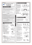
CONNECT THE CABLE TO THE INDOOR UNIT
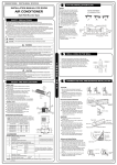
CONNECT THE CABLE TO THE OUTDOOR UNIT
Electrical work
I
N
D
O
O
R
U
N
I
T
Electric safety regulations for the initial Installation
1. If there is serious safety problem about the power supply, the technicians should refuse to install
the air conditioner and explain to the client until the problem is solved.
2. Power voltage should be in the range of 90%~110%of rated voltage.
3. The surge protector and main power switch with a 1.5 times capacity of Max. Current of the
unit should be installed in power circuit.
4. Ensure the air conditioner is grounded well.
5. According to the attached Electrical Connection Diagram located on the panel of the outdoor unit
to connect the wire.
6. All wiring must comply with local and national electrical codes and be installed by qualified and
skilled electricians.
7. An all-pole disconnection device which has at least 3mm separation distance in all pole and a residual
current device(RCD) with the rating of not exceeding 30mA shall be incorporated in the fixed wiring
according to the national rule.
8. An individual branch circuit and single receptacle used only for this air conditioner must be
available. See the following table for suggested wire sizes and fuse specifications:
Rated curr ent Nominal cross-sectional
of appliance
area
(A)
(mm2)
>3 and 6
0.75
>6 and 10
1
>10 and 16
1.5
2.5
>16 and 25
L
N
S
Terminals on the outdoor unit
L
N
S
Model A
Terminals on the indoor unit
L
Cover
NOTE:
1(L) 2(N)
Terminals on the indoor unit
L
N
S
L
N
S
Model A
Terminals on the indoor unit
L
N
Electrical box
cover
N
Power
supply
5
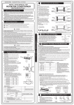
AIR PURGING AND TEST OPERATION
S
Less than 5m
Use vacuum pump
More than 5m
Use vacuum pump
Additional amount of refrigerant to be charged
Liquid side: 6.35mm
R22: (Pipe length-5)x30g/m
R410A: (Pipe length-5)x20g/m
Liquid side: 9.52mm:
R22: (Pipe length-5)x60g/m
R410A: (Pipe length-5)x40g/m
For the R407C refrigerant model, make sure the refrigerant added into air conditioner is liquid
form in any cases.
When relocate the unit to another place, using vacuum pump to perform evacuation.
S
L
CAUTION
N
Power
supply
Model B
Open the valve stem until it hits against
the stopper. Do not try to open it further.
Securely tighten the valve stem cap with
a spanner or the like.
Valve stem cap tightening torque. See
Tightening torque table.
Refrigerant
Outdoor
unit
A
Gas side
Liquid side
Flare nut
Indoor
unit
D
B
Packed valve
Stopper
Cap
C
Half union
Valve body
Valve stem
2. When using the Vacuum Pump
OUTDOOR INSALLATION PRECAUTION
Install the outdoor unit on a rigid base to prevent increasing noise level and vibration.
Determine the air outlet direction where the discharged air is not blocked.
In the case that the installation place is exposed to strong wind such as a seaside, make
sure the fan operating properly by putting the unit lengthwise along the wall or using a dust
or shield plates.
Specially in windy area, install the unit to prevent the admission of wind. If need suspending
installation, the installation bracket should accord with technique requirement in the
installation bracket diagram. The installation wall should be solid brick, concrete or the same
intensity construction, or actions to reinforce, damping supporting should be taken.
The connection between bracket and wall, bracket and the air conditioner should be firm,
stable and reliable.
Be sure there is no obstacle which block radiating air.
Incorrect
Correct
Barrier
2
L
Model B
Connective pipe length Air purging method
Terminals on the outdoor unit
1(L) 2(N)
Strong
wind
Strong
wind
S
Air and moisture in the refrigerant system have undesirable effects. Therefore, the indoor unit
and tubing between the indoor and outdoor unit must be leak tested and evacuated to remove
any noncondensables and moisture from the system.
Check that each tube(both liquid and gas side tubes) between the indoor and outdoor units have
been properly connected and all wiring for the test run has been completed.
Pipe length and refrigerant amount:
Terminal block of indoor unit
Terminals on
the outdoor unit
1
S
1. Air purging
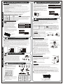
Connect the cable to the indoor unit
NOTE: Before performing any electrical work,
turn off the main power to the system.
1. The inside and outside connecting cable can
be connected without removing the front grille.
2. The indoor power cord type is H05VV-F or
H05V2V2-F, the outdoor power cord and
interconnected cord type is H07RN-F.
3. Lift the indoor unit panel up, remove the
electrical box cover by loosening the screw.
4. Ensure the colour of wires of outdoor unit and
the terminal Nos. are the same to the indoor s
respectively.
5. Wrap those cables not connected with terminals
with insulation tapes, so that they will not touch
any electrical components. Secure the cable onto
the control board withthe cord clamp.
N
Terminals on
the outdoor unit
Screw
The cable size and the current of thefuse
or switch are determined by the maximum
current indicated on the nameplate which
located on the side panel of the unit.
Please refer to the nameplate before
selecting the cable, fuse and switch.
Front Panel
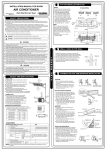
DRAIN JOINT INSTALLATION
1. Completely tighten the flare nuts, A, B, C, D, connect
the manifold valve charge hose to a charge port of the
Manifold valve
packed valve on the gas pipe side.
Compound meter Pressure gauge
2. Connect the charge hose connection to the vacuum
pump.
-76cmHg
3. Fully open the handle Lo of the manifold valve.
4. Operate the vacuum pump to evacuate. After starting
Handle Hi
Handle Lo
evacuation, slightly loose the flare nut of the packed
Charge
hose
valve on the gas pipe side and check that the air is
Charge hose
entering. (Operation noise of the vacuum pump changes
Vacuum pump
and a compound meter indicates 0 instead of minus)
5. After the evacuation is complete, fully close the handle
Lo of the manifold valve and stop the operation of the
vacuum pump.
Make evacuation for 15 minutes and more and check
Packed valve
that the compound meter indicates -76cmHg(-1.0x10⁵Pa).
O
6. Turn the stem of the packed valve B about 45 counterclockwise for 6~7 seconds after the gas coming out, then
tighten the flare nut again. Make sure the pressure display
in the pressure indicator is a little higher than the atmosphere
pressure.
7. Remove the charge hose from the Low pressure charge hose.
8. Fully open the packed valve stems B and A.
9. Securely tighten the cap of the packed valve.
NOTE: The drain joint is slightly different according to the
different outdoor unit.
For the drain joint with the seal(Fig.A), first fit the seal onto
the drain joint, then insert the drain joint into the base pan
hole of outdoor unit, rotate 90 to securely assemble them.
To install drain joint as shown in Fig.B, insert the drain
joint into the base pan hole of outdoor unit until it remains
fixed with a clicking sound. Connecting the drain joint with
an extension drain hose (Locally purchased), in case of the
water draining off the outdoor unit during the heating mode.
3
3. Safety and leakage check
Drain joint
Seal
Base pan hole
of outdoor unit
(A)
(B)
REFRIGERANT PIPE CONNECTION
CAUTION
Indoor unit
check point
D
C
B
A
Cover
Outdoor unit
check point
4. Test running
Flaring
1. Cut a pipe with a pipe cutter.
2. Remove flare nuts attached to indoor and
outdoor unit, then put them on pipe/tube
having completed burr removal and flare
the pipe.
3. Firmly hold copper pipe in a die in the
dimension shown in the table below.
90
Bar
A(mm)
Outer diam.
(mm)
Max.
Min.
6.35
1. Soap water method:
Apply a soap water or a liquid neutral detergent on the indoor
unit connections and outdoor unit connections by a soft brush
to check for leakage of the connecting points of the piping. If
bubbles come out, it indicates that the pipes have leakage.
2. Leak detector
Use the leak detector to check for leakage.
A: Lo packed valve B: Hi packed valve
C and D are ends of indoor unit connection.
1.3
0.7
9.52
1.6
1.0
12.7
16
1.8
2.2
1.0
2.0
Tightening connection
Align pipes to be connected.
Sufficiently tighten the flare nut with fingers,
and then tighten it with a spanner and torque
wrench as shown.
Excessive torque can break nut depending
on installation conditions.
O
Oblique Roughness
Copper pipe
Indoor unit tubing
Outer
diam.
6.35mm
9.52mm
12.7mm
16mm
Flare nut
Burr
Handle
"A"
U
N
I
T
Terminal block of outdoor unit
Terminals on the indoor unit
Minimum norminal cross-sectional area of conductors:
,
O
U
T
D
O
O
R
1. Remove the electrical control board cover from the
outdoor unit by loosening the screw.
2. Connect the connective cables to the terminals as
identified with their respective matched numbers
on the terminal block of indoor and outdoor units.
3. Secure the cable onto the control board with the cord
clamp.
4. To prevent the ingress of water, form a loop of the
connective cable as illustrated in the installation
diagram of indoor and outdoor units.
5. Insulate unused cords (conductors) with PVC-tape.
Process them so they do not touch any electrical
or metal parts.
Bar
Clamp handle
Perform test operation after completing gas leak check at the flare nut connections and electrical
safety check.
Check that all tubing and wiring have been properly connected.
Check that the gas and liquid side service valves are fully open.
1. Connect the power, press the ON/OFF button on the remote controller to turn the unit on.
2. Use the MODE button to select COOL, HEAT, AUTO and FAN to check if all the functions works
well.
3. When the ambient temperature is too low(lower than 17OC), the unit cannot be controlled by the
remote controller to run at cooling mode, manual operation can be taken. Manual operation is
used only when the remote controller is disable or maintenance necessary.
Hold the panel sides and lift the panel up to an angle until it remains fixed with a clicking sound.
Press the Manual control button to select the AUTO or COOL, the unit will operate under Forced
AUTO or COOL mode(see User Manual for details).
4. The test operation should last about 30 minutes.
Pipings
Tightening
torque(N.cm)
Additional tightening
torque(N.cm)
1500
(153kgf.cm)
2500
(255kgf.cm)
1600
(163kgf.cm)
3500
(357kgf.cm)
4500
(459kgf.cm)
3600
(367kgf.cm)
4700
(479kgf.cm)
2600
(265kgf.cm)
Manual control
button
AUTO/COOL