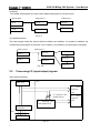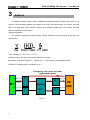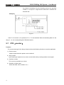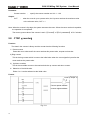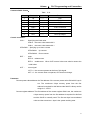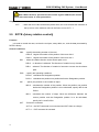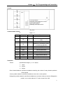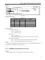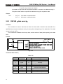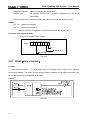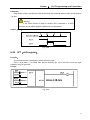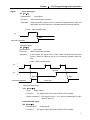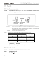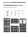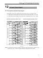
1
This user manual describes all items concerning the operation of
this CNC system in detail. However, it is impossible to give particular
descriptions for all unnecessary or unallowable operations due to length
limitation and products application conditions;therefore, the items not
presented herein should be considered impractical or unallowable.
Copyright is reserved to GSK CNC Equipment Co., Ltd. It is illegal
for any organization or individual to publish or reprint this manual. GSK CNC
Equipment Co., Ltd. reserves the right to ascertain their legal liability.
I
GSK 25i Milling CNC System
User Manual
Preface
Your Excellency,
We are honored by your purchase of this GSK 25i Milling Machining
Center CNC System made by GSK CNC Equipment Co., Ltd.
This book is “PLC Programming and Connection” section of the User
Manual Volume Ⅱ.
Special caution:
The power supply fixed on/in the cabinet is exclusively used for the
CNC system made by GSK.
It can't be applied to other purposes, or else it may cause serious
danger.
II
Volume Ⅱ
PLC Programming and Connection
Warning and Precaution
Accident may occur by improper connection and operation!This system can
only be operated by authorized and qualified personnel.
Please read this manual carefully before operation!
Please read this manual and a manual from machine tool builder carefully before
installation, programming and operation, and strictly observe the requirements.
This manual includes the precautions for protecting user and machine tool. The
precautions are classified into Warning and Caution according to their bearing on safety,
and supplementary information is described as Note. Read these Warnings, Caution and
Note carefully before operation.
Warning
User may be injured or equipment be damaged if operations instructions and
procedures are not observed.
Caution
Equipment may be damaged if operation instructions or procedures are not
observed.
Note
It is used to indicate the supplementary information other than Warning and Caution.
III
GSK 25i Milling CNC System
User Manual
Announcement
● This manual describes various possibilities as much as possible.
However, operations allowable or unallowable cannot be explained
one by one due to so many possibilities that may involve with, so the
contents that are not specially stated in this manual shall be
considered as unallowable.
Caution
● Functions, technical indexes (such as precision and speed) described
in this user manual are only for this System. Actual function
deployment and technical performance of a machine tool with this
CNC system are determined by machine tool builder’s design, so
functions and technical indexes are subject to the user manual from
machine tool builder.
● Refer to the user manual from machine tool builder for function and
meaning of keys on control panel.
IV
Volume Ⅱ
PLC Programming and Connection
Precautions
■ Delivery and storage
● Packing box over 6 layers in pile is unallowed.
● Never climb the packing box, neither stand on it, nor place heavy objects on it.
● Do not move or drag the products by the cables connected to it.
● Forbid collision or scratch to the panel and display screen.
● Avoid dampness, insolation and drenching.
■ Open-package inspection
● Confirm that the products are the required ones.
● Check that the products are not damaged in delivery.
● Confirm that the parts in packing box are in accordance with the order.
● Contact us in time if any inconsistence, shortage or damage is found.
■ Connection
● Only qualified personnel can connect the System or check the connection.
● The System must be earthed, and the earth resistance must be less than 0.1Ω.
The earth wire cannot be replaced by zero wire.
● The connection must be correct and firm to avoid any fault or unexpected
consequence.
● Connect with surge diode in the specified direction to avoid damage to the
System.
● Switch off power supply before plugging out or opening electric cabinet.
■ Troubleshooting
● Only competent personnel are supposed to inspect the System or machine.
● Switch off power supply before troubleshooting or changing components.
● Check for fault when short circuit or overload occurs. Restart can only be done
after troubleshooting.
● Frequent switching on/off of the power is forbidden, and the interval time should
be at least 1 min.
V
GSK 25i Milling CNC System
User Manual
Safety Responsibility
Manufacturer’s Responsibility
——Be responsible for the danger which should be eliminated and/or controlled on
design and configuration of the provided CNC systems and accessories.
——Be responsible for the safety of the provided CNC systems and accessories.
——Be responsible for the provided information and advice for the users.
User’s Responsibility
——Be trained with the safety operation of CNC system and familiar with the safety
operation procedures.
——Be responsible for the dangers caused by adding, changing or altering to the
original CNC systems and the accessories.
——Be responsible for the failure to observe the provisions for operation, adjustment,
maintenance, installation and storage in the manual.
All specifications and designs herein are subject to change without
further notice.
This manual is reserved by end user.
We are full of heartfelt gratitude to you for supporting us in the use of
GSK’s products.
VI
Volume Ⅱ
PLC Programming and Connection
Contents
Ⅰ PLC PROGRAMMING ...................................................................................................................1
PART 1
PROGRAMMING.............................................................................................................2
1 Sequence Program Creating Process ...................................................................................3
1.1 GSK25i PLC specifications.....................................................................................................3
1.2 What ’s a Sequence Program ................................................................................................3
1.3 Assignment of interface specifications(step 1) ...............................................................4
1.4 Establishment of ladder diagram(step 2) ........................................................................4
1.5 Sequence program debugging(step 3) ............................................................................4
2 Sequence Program..................................................................................................................5
2.1 Execution process of sequence program .............................................................................5
2.2 Repetitive cycle ........................................................................................................................6
2.3 Priority of execution(1st level, and 2nd level).........................................................................6
2.4 Sequence program structure..................................................................................................7
2.5
Processing I/O (input/output) signals ..................................................................................8
2.6
Interlocking ........................................................................................................................... 11
3
Address ...............................................................................................................................12
3.1 Machine →PLC address(X)............................................................................................13
3.2 PLC→machine side address(Y) .....................................................................................15
3.3 PLC→CNC address(G)....................................................................................................16
3.4 CNC→PLC address(F) ....................................................................................................17
3.5 Internal relay address(R) .................................................................................................17
3.6 Address of keep relay(K) .................................................................................................18
3.7 Addresses(A) for message selection ..................................................................................18
3.8 Address of counter(C) ......................................................................................................19
3.9 Address of timer (T).........................................................................................................19
3.10 Address(D)of data table.................................................................................................20
3.11 Label address(L) .............................................................................................................20
3.12 Subprogram numbers(P) ...............................................................................................20
4 PLC Basic Instruction ...........................................................................................................21
4.1 LD, LDI, OUT, OUTI command ............................................................................................22
4.2 AND, ANI command...............................................................................................................22
4.3 OR, ORI command ................................................................................................................23
4.4 ORB command .......................................................................................................................23
4.5 ANB command .......................................................................................................................24
5 PLC Functional Instructions.................................................................................................25
5.1 END1(1st level sequence program end) ........................................................................26
5.2 END2(2nd level sequence program end) .......................................................................27
5.3 TMR(Timer)........................................................................................................................27
5.4 TMRB(fixed timer).............................................................................................................28
5.5 TMRC(timer) ......................................................................................................................29
5.6 DECB(binary decode) ......................................................................................................31
5.7 CTR(counter).....................................................................................................................32
VII
GSK 25i Milling CNC System
5.8
5.9
5.10
5.11
5.12
5.13
5.14
5.15
5.16
5.17
5.18
5.19
5.20
5.21
5.22
5.23
5.24
5.25
5.26
5.27
5.28
5.29
5.30
5.31
5.32
5.33
5.34
5.35
5.36
5.37
5.38
5.39
5.40
5.41
5.42
5.43
5.44
6
PART 2
1
VIII
User Manual
CTRC(counter) ................................................................................................................. 34
ROTB(binary rotation control) ........................................................................................ 36
CODB(binary code conversion) ................................................................................... 38
MOVE(logical product transfer).................................................................................... 40
MOVOR(data transfer after logical sum) .................................................................... 41
MOVB (transfer of 1 byte) ............................................................................................ 42
MOVW (transfer of 2 bytes)......................................................................................... 43
MOVN(transfer of an arbitrary number of bytes)....................................................... 43
PARI(parity check) ......................................................................................................... 44
DCNVB(extended data conversion) ............................................................................ 45
COMPB(binary compasion).......................................................................................... 47
COIN(coincidence check) ............................................................................................. 49
DSCHB(data search)..................................................................................................... 50
XMOVB(binary indexed modifier data transfer)......................................................... 51
ADDB(addition).................................................................................................................... 53
SUBB(binary subtraction) ............................................................................................. 55
MULB(binary multiplication) ......................................................................................... 56
DIVB(binary division) ..................................................................................................... 58
NUMEB(definition of binary constant)......................................................................... 60
DIFU(Edge Up detection) ............................................................................................. 61
DIFD(Edge Down detection) ........................................................................................ 62
SFT(shift register) .......................................................................................................... 63
EOR(EOR) ...................................................................................................................... 64
AND(logical and) ............................................................................................................ 66
OR(logical or).................................................................................................................. 67
NOT(logical not) ............................................................................................................. 69
COM(common line control)........................................................................................... 70
COME(common line control end) ................................................................................ 71
JMP(jump)....................................................................................................................... 71
JMPE(jump end) ............................................................................................................ 73
CALL(conditional subprogram call) ............................................................................. 73
CALLU(uncoditional subprogram call) ........................................................................ 74
JMPB(label jump 1) ....................................................................................................... 75
JMPC(label jump 2) ....................................................................................................... 76
LBL(label) ........................................................................................................................ 76
SP(subprogram) ............................................................................................................. 77
SPE(end of a subprogram)........................................................................................... 78
Ladder Writing Limit...........................................................................................................79
FUNCTION ......................................................................................................................80
Preparations for operatoin .............................................................................................81
1.1 Emergency stop..................................................................................................................... 81
1.2 CNC overtral signal ............................................................................................................... 82
1.3 Alarm signal............................................................................................................................ 83
1.4 Interlock................................................................................................................................... 83
Volume Ⅱ
1.5
PLC Programming and Connection
Operation mode selection .....................................................................................................84
2 Manual operation...................................................................................................................85
2.1 JOG feed/incremental feed...................................................................................................85
2.2 MPG / Step feed .....................................................................................................................86
3 Reference Point Return.........................................................................................................88
3.1 Manual reference point return ..............................................................................................88
4 Automatic operation..............................................................................................................91
4.1 Cycle start/feed hold ..............................................................................................................91
4.2 reset .........................................................................................................................................94
4.3 Testing a program ..................................................................................................................95
4.4 Optional block skip.................................................................................................................98
4.5 Program restart.......................................................................................................................99
5 Feedrate Control..................................................................................................................101
5.1 Rapid traverse rate ..............................................................................................................101
5.2 Override .................................................................................................................................102
6 Auxiliary Function ...............................................................................................................104
6.1 Miscellaneous function ........................................................................................................104
6.2 Auxiliary function lock ..........................................................................................................109
7 Spindle Speed Function......................................................................................................111
7.1 Spindle speed control mode ............................................................................................... 111
7.2 Spindle speed arrival signal................................................................................................ 113
7.3 Rigid tapping ......................................................................................................................... 114
8 Tool function........................................................................................................................115
8.1 T command tool change......................................................................................................... 115
9 Programming command .....................................................................................................115
9.1 Custom macro program ......................................................................................................... 115
Ⅱ CONNECTION ...........................................................................................................................118
1
2
GSK25i System Box Interface..........................................................................................121
Operation panel interface.................................................................................................122
2.1 Sketch map of machine operation panel interface.............................................................122
2.2 GSK 25i CNC system communication interface XS21......................................................122
2.3 Emergency stop power-on interface ....................................................................................122
3
4
5
6
7
8
9
10
11
12
I/O Interface .......................................................................................................................123
Interconnection Graph .....................................................................................................125
PC serial communication wire.........................................................................................126
MPG Wiring .......................................................................................................................127
Operation Panel Signal Line ............................................................................................129
Ethernet Communication Connection.............................................................................130
Connected with the Spindle Servo ..................................................................................132
Connected with the Spindle Converter .........................................................................133
Connection Method of Z Brake, System Power-on Control ........................................134
I/O Input, Output Signal..................................................................................................135
12.1 Connection method of input signal.....................................................................................135
12.2 Connection method of output signal ..................................................................................136
IX
GSK 25i Milling CNC System
User Manual
12.3 Definition of input signal point ............................................................................................ 137
12.4 Definition of output signal point .......................................................................................... 139
APPENDIX ......................................................................................................................................141
1 Signal table(address order) ................................................................................................141
2 Contour installation dimension drawing...........................................................................145
X
Volume Ⅱ
PLC Programming and Connection
Ⅰ PLC PROGRAMMING
1
GSK 25i Milling CNC System
Part 1
2
User Manual
Programming
Volume Ⅱ
1
1.1
PLC Programming and Connection
Sequence Program Creating Process
GSK25i PLC specifications
Specification of GSK25i PLC are as follows(see Table 1-1):
Table 1-1
GSK25i
Specification
Ladder, command table
Number of ladder level
2
st
1 level execution period
8ms
Mean processing time of basic command
0.5(μs/step)
Program capacity
12000 steps
Command
P:10
Functional command:44
Internal relay (R)
Data table (D)
Meter (C)
Timer (T)
PLC alarm detection (A)
Keep relay (K)
Label
(L)
Subprogram
(P)
Machine →PLC(X)
PLC→machine (Y)
CNC→PLC(F)
PLC→CNC(G)
1.2
PLC
Programming method language
1100 bytes(R0 to R1099)
1860 bytes (D0 to D1859)
400 bytes (C0 to C399)100PCS
200 bytes (T0 to T199)100PCS
32 bytes(A0 to A31)
32 bytes(K0 to K31)
9999(L1~L9999)
512(P1~P512)
128 bytes(X0 to X127)
128 bytes (Y0 to Y127)
256 bytes (F0 to F255)
256 bytes (G0 to G255)
What ’s a Sequence Program
A sequence program is a program for sequence control of machine tools and other systems.
The program is converted into a format to enable CPU execute encoding and arithmetic
processing, and stored into RAM. CPU reads out every instruction stored in the memory at a
high-speed and execute the program by arithmetic operation
The sequence program is written firstly from ladder.
3
GSK 25i Milling CNC System
1.3
User Manual
Assignment of interface specifications(step 1)
After deciding the control object specification, calculate the number of input/output signal points,
create the interface specification.
For input/output interface signals, see Chapter 4.
1.4
Establishment of ladder diagram(step 2)
Express the control operations decided by 25i ladder diagram. For the timer, meter, etc, which
cannot be expressed with the functional instructions.
The edited ladder should be converted into the corresponding PLC instruction i.e. instruction list
to store.
1.5
Sequence program debugging(step 3)
The sequence program can be debugged in two ways:
1) Debug by simulator
Instead of the machine, connect a simulator (consisting of lamps and switches). Switch
ON/OFF stands for the input signal state of machine, lamp ON/OFF for the output signal state.
2) Actual operation debugging
Debug sequence program through operating the machine. Do measures against the
unexpected affairs before debugging.
4
Volume Ⅱ
2
PLC Programming and Connection
Sequence Program
Since PLC sequence control handled by software and operates on principle difference from a
general relay circuit, the sequence control method must be fully understood in order to design PLC
sequence program.
2.1
Execution process of sequence program
In general relay control circuit, each relay operates at approximately the same time, in the figure
below for example, when relay A operate, the relay D and E operate at approximately the same
time(when contacts B and C are off)., In PLC sequence control, each relay of circuit operates
sequentially. When relay A operates, relay D operates, then relay E(see Fig.2-1). Thus each relay
operates in sequence which can be written as a ladder diagram. (Programmed sequence).
A
B
D
A
C
E
Fig. 2-1(a)
Fig.2.1(b) and (c) illustrate operations varying from the relay circuit to PLC programs.
A
C
B
A
C
Fig. 2-1(b)
A
C
A
C
B
Fig.2-1(c)
5
GSK 25i Milling CNC System
(1)
User Manual
Relay circuit
In Fig. 2.1(b) and (c), the operations are the same. Turning on A turns on B and C. Turning on C
turns off B.(2)
PLC program
In Fig.2.1(b), as in the relay circuit, turning on A turns on B and C, and after one cycle of the PLC
sequence, turns off B. But in Fig.2.1(c), turning on A turns on C, but does not turn on
2.2
Repetitive cycle
The PLC executes the ladder diagram from the beginning to the end . When the ladder diagram
ends, the program starts over from the beginning. This is called repetitive operation.
The execution time from the beginning to the end of the ladder diagram is called the sequence
processing time. The shorter the process time is, the better the signal response becomes.
Priority of execution(1st level, and 2nd level)
2.3
GSK25i PLC consists of two parts: 1st level sequence part, 2nd level sequence part. They have
different execution period.
The 1st level sequence part operates every 8 ms, which can deal with the short pulse signal with
high-speed response).
The 2nd level sequence part operates every 8*n ms. Here N is a dividing number for the 2nd level
sequence part. The 2nd level sequence part is divided into V part, and every part is executed every
8ms.
1st level
END1
Specifies the end of the
1st level sequence part
sequence part
Division 1
Division 2
nd
2
level
sequence program
Division n
END2
Fig. 2-2
6
Specifies the end of the
2nd level sequence part
Volume Ⅱ
PLC Programming and Connection
GSK 25i PLC is solely executed in PLC-AVR single chip, and the first 1ms of each 8ms is the
communication time of CNC reading or writing PLC data. The fifth 1ms is the time that the PLC
receives the system control signal(F, X)and uploads the control result data(G, Y parameter)to the
external I/O interface(X, Y), except for the time responding the interruption to exchange the data, the
PLC executes the ladder operation at the rest time.
8 ms
1st level
3 ms
8 ms
3 ms
Division 1
nd
2
Division 2
8 ms
3 ms
Division n
level
CNC use
Fig. 2-3
After the last 2nd level sequence part (division n) is executed, the sequence program is executed
again from the beginning. Thus, when the dividing number is n, the cycle of execution is 8*n ms. The
1st level sequence operates every 8ms, and the 2nd level sequence every 8*n ms. If the steps of the
1st level sequence is increased, the steps of the 2nd level sequence operating within 4ms becomes
less, thereby increasing the dividing number and making the processing time longer. Therefore, it is
desirable to program so as to reduce the 1st level sequence to a minimum.
2.4
Sequence program structure
With the conventional PLC, a ladder program is described sequentially. By employing a ladder
language that allows structured programming, the following benefits are derived:
1. A program can be understood and developed easily
2. A program error can be found easily.
3.When an operation error occurs, the cause can be found easily.
Three major structured programming capabilities are supported:
1) Subprogram
A subprogram can consist of a ladder sequence as the processing unit.
Fig. 2-4
7
GSK 25i Milling CNC System
User Manual
2) Nesting
The Ladder subprograms can call the other ladder subprogram to execute the job.
Main program
Subprogram 1
Subprogram 2
Job A
Job A1
Job A11
Job B
Job A12
Job An
Fig. 2-5
3) Conditional branch
The main program loops and checks whether conditions are satisfied. If a condition is satisfied, the
corresponding subprogram is executed. If the condition is not satisfied, the subprogram is jumpped.
Main program
Subprogram 1
Process 11
Process 1
State 1
Process 12
State 2
Process 2
Process 13
Fig. 2-6
2.5
Processing I/O (input/output) signals
Input signal processing:
CNC
CNC—PLC
PLC
1st
level
sequence
part
nd
2
sequence part
starting memory
nd
2
sequence
part
input signal memory
Input signals from
machine tool
8ms
IO interface
Fig. 2-7
8
2nd
level
sequence
part
Volume Ⅱ
PLC Programming and Connection
Output signal processing:
CNC
PLC
1st level
sequence part
CNC—PLC
Share memory
2nd level
output memory from
sequence part
machine tool
8ms
IO interface
Fig. 2-8
2.5.1 Input signal processing
(1)Input memory of NC
The input signals from NC are loaded in memory of NC and are transferred to the PLC at
intervals of 8ms. Since the 1st level sequence part directly refer to these signal and process
operations.
(2)Input signal memory to machine tool
The input signal memory stores signals transferred from the machine tool at intervals of 8ms
period. Since the 1st level sequence part directly refer to these signal and process operations.
(3)2nd level input signal memory
The 2nd level input signal memory is also called as 2nd level synchronous input signal memory.
The stored signals are processed by the 2nd level sequence part. State of the signals set this memory
synchronizes with that of 2nd level sequence part.
Input memory Signals from NC and machine tool are transferred to the 2nd level input signal
memory only at the beginning of execution of the 2nd level sequence part. Therefore, the state of the
2nd level synchronous input signal memory does not change from the beginning to end of the
execution of the 2nd level sequence part.
2.5.2 Output signal processing
(1)NC output memory
The output signals are transferred form the PLC to the NC output memory at intervals of 8ms.
(2)Output signals to machine tool
Output signal to the machine tool from PLC output signal memory to the machine tool at intervals
of 8ms.
9
GSK 25i Milling CNC System
User Manual
Note:
The state of the NC input memory, NC output memory, input signals from machine, input/output
memory signals to machine can be checked by using the PC self-diagnosis function. The
self-diagnosis number specified is the address number used by the sequence program.
2.5.3 Synchronous processing the short pulse signal
1st program can process the short pulse signal. When the short pulse signal change is less than
8ms, i.e.when the system executes the 1st program, the input signal state can change to cause the
followings.
Fig. 2-9
When A=0 and B1=1,A becomes 1, at the moment, the system executes the next
ladder statement to make B2=1. so, B1 and B2 become 1.
A
R
R
B1
R
B2
END1
Fig. 2-10
When the medium relay R synchronously processes the signal A, B1, B2 are not 1 at the same
time.
10
Volume Ⅱ
PLC Programming and Connection
2.5.4 Difference state of signals between 1st level and 2nd level
The state of the same input signal may be different in the 1st level and 2nd level sequences. That
is, at 1st level, processing is performed using input signal memory and at 2nd level, processing is
performed using the 2nd level synchronous input signal memory. Therefore, it is possible for a 2nd level
sequence execution at the worst, compared with a 1st level input signal.
This must be kept in mind when writing the sequence program.
2nd division of 2nd
level sequence part
Fig. 2-11
When the processing is 1st 8ms, A=1, and B=1 after 1st sequence part is executed. At the same
time, 2nd sequence part is started to execute A=1 is stored to the 2nd sequence part and the 1st
division of 2nd sequence part is executed.
When the processing is 2nd 8ms, A=0, and B=0 after 1st sequence part is executed. And then
2nd division of 2nd sequence part is executed, at this time, A is still 1. So C=1.
So, B and C are different.
2.6
Interlocking
Interlocking is externally important in sequence control safety.
Interlocking with the sequence program is necessary. However, interlocking with the end of the
electric circuit in the machine tool magnetic cabinet must not be forgotten. Even though logically
interlocked with the sequence program (software), the interlock will not work when trouble occurs in
the hardware used to execute the sequence program. Therefore, always provide an interlock inside
the machine tool magnetic cabinet panel to ensure operator safety and to protect the machine from
damage.
11
GSK 25i Milling CNC System
3
User Manual
Address
An address shows a signal location. Addresses include input/output signals with respect to the
machine, the input/output signals with respect to the CNC, the internal relays, the meters, the keep
relays, and data table. Each address consists of an address number and a bit number. Its serial
number regulations are as follows:
Address regulations:
The address comprises the address type, address number and the bit number in the format as
shown below:
Type: including X, Y, R, F, G K, A, D ,C, T
Address number: decimal serial number stands for one byte.
Bit number: octal serial number, 0~7 stands for 0~7 bit of byte of front address number
GSK25i PLC address type is as follows Fig.3-1:
Emergency stop, jump and other
high-speed signals
Machine to PLC
MT
X
PLC to NC
F
NC to PLC
25i
Input signal
PLC to machine
Nesting
Y
PLC
Output signal
Fig. 3-1
12
G
CNC
Volume Ⅱ
PLC Programming and Connection
Table 3-1
Address
3.1
Address explanation
Address range
X
machine→PLC(128 bytes)
X0~X127
Y
PLC→machine(128 bytes)
Y0~Y127
F
CNC→PLC(256 bytes)
F0~F255
G
PLC→CNC(256 bytes)
G0~G255
R
Internal relay(1100 bytes)
R0~R1099
D
Data register(1860 bytes)
D0~D1859
C
Counter (400 bytes)
C0~C 399
T
Timer (200 bytes)
T0~T199
A
Timer preset data register (32 bytes)
A0~A31
K
Keep relay(32 bytes)
K0~K31
Machine →PLC address(X)
X addresses of GSK25i PLC are divided into two:
1. X addresses are assigned to IO input interface.
2. X addresses are assigned to the input press keys on MDI panel.
3.
X addresses are assigned to other external interfaces, such as the spindle, MPG control signal
input.
3.1.1
Assignment of IO module X address
The addresses are from X9 to X119. Its type is INT8U, 111 types.
The signal specification of X addresses can be customized by customer according to the actual
operation. X addresses are used to connect the machine tool with the ladder. For the initial definition
of input address, see Chapter Four Connection.
3.1.2
Assignment of MDI panel X address
The addresses are from X0 to X8, 9 bytes. They correspond to the press keys on MDI panel.
The corresponding relationship between them and the press keys on the standard panel is as Fig.
3-2:
13
GSK 25i Milling CNC System
User Manual
Table 3-2
INPUT KEY ON
OPERATION PANEL
PLC
ADDRESS
INPUT KEY ON
OPERATION PANEL
PLC
ADDRESS
Auto mode
X0.0
-Z
X3.5
Edit mode
X0.1
-4
X3.6
MDI mode
X0.2
-5
X3.7
Manual mode
X0.3
Spindle CW
X4.0
MPG mode
X0.4
Spindle stop
X4.1
Zero mode
X0.5
Spindle CCW
X4.2
DNC mode
X0.6
Spindle orientation
X4.3
USER1
X0.7
F0/0.001
X4.4
Single block
X1.0
25%/0.01
X4.5
Jump
X1.1
50%/0.1
X4.6
Machine lock
X1.2
100%/1
X4.7
Auxiliary lock
X1.3
+4
X1.4
+Z
X1.5
-Y
X1.6
Tool magazine infeed
X5.3
+5
X1.7
Tool retraction
X5.4
Dry run
X2.0
Tool change manipulator
X5.5
Overtravel release
X2.1
Tool magazine CW
X5.6
Optional stop
X2.2
Tool magazine zero
X5.7
Program restart
X2.3
Clamp/release
X6.0
+X
X2.4
USR2
X6.1
Rapid
X2.5
USR3
X6.2
Step
X2.6
USR4
X6.3
-X
X2.7
Feed hold
X6.4
Cooling
X3.0
Cycle start
X6.5
Lubricating
X3.1
Tool magazine CCW
X6.6
X3.2
Feedrate override, up to
24-gear(no output light)
X7.0-X7.4
X3.3
Spindle override, up to
16-gear(no output light)
X8.0-X8.3
X3.4
Emergency stop
X8.4
Chip removal
Working light
+Y
14
Volume Ⅱ
PLC Programming and Connection
3.1.3 MPG signal input X address
Table
3-3
MPG signal input
HDC0_STP
3.2
(MPG emergency stop signal)
PLC address
X121.0
HDC0_MX100(MPG federate override)
X120.0
HDC0_MX10 (MPG federate override)
X120.1
HDC0_MX1
X120.2
(MPG federate override)
HDC0_5
(5 axis)
X120.3
HDC0_4
(4th axis)
X120.4
HDC0_Z
(Z axis)
X120.5
HDC0_Y
(Y axis)
X120.6
HDC0_X
(X axis)
X120.7
th
PLC→machine side address(Y)
Y addresses of GSK25i
PLC are divided into three:
1. Y addresses are assigned to IO input interface.
2. Y addresses are assigned to the indicators on MDI panel.
3. Y addresses are assigned to the indicators on MPG.
3.2.1 Y address of I/O output interface
The addresses are from Y8 to Y119. Its type is INT8U, 112 types.
The signal specification of Y addresses can be customized by customer according to the actual
operation. Y addresses are used to connect the machine tool with the ladder. For the initial definition
of input address, see Chapter Four Connection.
3.2.2 Assignment of IO module Y address
The addresses are from Y0 to Y7, 8 bytes. They correspond to the indicators on MDI panel, and
their signal definitions cannot be changed by user.
Addresses and indicators are as follows Table.3-4:
15
GSK 25i Milling CNC System
User Manual
Table 3-4
OUTPUT KEY ON
OPERATION PANEL
PLC
ADDRESS
OUTPUT KEY ON
OPERATION PANEL
PLC
ADDRESS
Auto key indicator
Y0.0
-Z key indicator
Y3.5
Edit key indicator
Y0.1
-4 key indicator
Y3.6
MDI key indicator
Y0.2
-5 key indicator
Y3.7
Manual key indicator
Y0.3
Spindle CW key indicator
Y4.0
MPG key indicator
Y0.4
Spindle stop key indicator
Y4.1
Zero key indicator
Y0.5
Spindle CCW key indicator
Y4.2
DNC key indicaor
Y0.6
Spindle orientation key indicator
Y4.3
USER1 key indicaor
Y0.7
F0/0.001 key indicator
Y4.4
Single block key indicaor
Y1.0
25%/0.01 key indicator
Y4.5
Jump key indicator
Y1.1
50%/0.1 key indicator
Y4.6
Machine lock indicator
Y1.2
100%/1 key indicator
Y4.7
Auxiliary lock indicator
Y1.3
Tool magazine infeed key indicator
Y5.3
+4 key indicator
Y1.4
Tool retraction key indicator
Y5.4
+Z key indicator
Y1.5
Tool change key indicator
Y5.5
-Y key indicator
Y1.6
Tool magazine CW key indicator
Y5.6
+5 key indicator
Y1.7
Tool magazine zero key indicator
Y5.7
Dry run key indicator
Y2.0
Clamp/release tool key indicator
Y6.0
Overtravel release key indicator
Y2.1
USR2 key indicator
Y6.1
Optional stop key indicator
Y2.2
USR3 key indicator
Y6.2
Program restart key indicator
Y2.3
USR4 key indicator
Y6.3
+X key indicator
Y2.4
Feed hold key indicator
Y6.4
Rapid key indicator
Y2.5
Cycle start key indicator
Y6.5
Step key indicator
Y2.6
Tool magazine CCW key indicator
Y6.6
-X key indicator
Y2.7
X zero return indicator
Y7.0
Cooling key indicator
Y3.0
Y zero return indicator
Y7.1
Lubricating key indicator
Y3.1
Z zero return indicator
Y7.2
Chip removal key indicator
Y3.2
th
Y7.3
th
4 zero return indicator
Working light key indicator
Y3.3
5 zero return indicator
Y7.4
+Y key indicator
Y3.4
System alarms
Y7.6
3.2.3 MPG signal light output
MPG signal light output
3.3
Y120.0
PLC→CNC address(G)
Addresses are from G0 to G255. Type: INT8U,256 bytes. G addresses are the signals from PLC
to NC, and these signals have been defined in designing the CNC system and cannot be modified.
16
Volume Ⅱ
PLC Programming and Connection
The concrete is referred to Appendix 1.
3.4
CNC→PLC address(F)
A ddresses are from F0 to F255. Type: INT8U,256 bytes. F addresses are the signals from NC to
PLC, and these signals have been defined in designing the CNC system and cannot be modified. The
concrete is referred to Appendix 1.
3.5 Internal relay address(R)
The address area is cleared to zero when the power is turned on.
Type: INT8U, with 1100 bytes.
Fig. 3-2
Note: the addresses from R1000 are used by PLC. For example: ADDB, SUBB, COMB functional command
operation result are output to the register:
#7
R1000
#6
#5
#4
Overflow
#3
#2
#1
#0
Negative
Zero
Fig. 3-3
17
GSK 25i Milling CNC System
3.6
User Manual
Address of keep relay(K)
The area is used for the keep relays and PLC parameters. Since this area is nonvolatile, the
content of the memory do not disappear even when the power is turned off.
Type: INT8U, with 32 bytes
Fig. 3-4
3.7 Addresses(A) for message selection
The address area is cleared to zero when the power is turned on.
Type: INT8U, with 32 bytes.
Fig. 3-5
18
Volume Ⅱ
PLC Programming and Connection
3.8 Address of counter(C)
The area is used as storing current counting value in meter.
Type: 400 bytes.
C1~C100: count range: 0~65535, can set increase/reducing count, and the counting value
does not disappear even when the power is turned off.
Fig. 3-6
3.9
.
Address of timer (T)
Type: 200 bytes.
T1~T100,The timing value does not disappear even when the system is turned off.
19
GSK 25i Milling CNC System
User Manual
Fig. 3-7
3.10
Address(D)of data table
Each data register has 8-bit, two continuous data registers can store 16-bit data, four continuous
data registers can store 32-bit data.
The content of the memory do not disappear even when the power is turned off.
Number of data table:D0~D1859,1860 bytes.
Fig. 3-8
3.11
Label address(L)
Label addresses are used to specify jump destination labels and LBL labels in JMPB instructions.
Range: L0~L9999
3.12
Subprogram numbers(P)
Subprogram numbers are used to specify jump destination subprogram labels and SP instruction
subprogram labels in CALL instruction.
Range: P0~P511.
20
Volume Ⅱ
4
PLC Programming and Connection
PLC Basic Instruction
Designing a sequence program begins with writing a ladder diagram. The ladder diagram is
written using relay contact symbols and functional instruction code. Logic written in the ladder
diagram is entered as a sequence program in the Programmer. There are two sequence program
entry methods. One is the entry method with the mnemonic language (PLC instructions such as RD,
AND, OR). The other is the relay symbols of the ladder diagram. When the relay symbol method is
used, the ladder diagram format can be used and programming can be performed without
understanding the PLC instruction format.
Actually, however, the sequence program entered by the relay symbol method is also internally
converted into the instruction corresponding to the PLC instruction.
The basic instructions are often used when the sequence program is designed, and the execute
one-bit operation.
GSK25i basic instructions are as follows(see Table 4-1):
Table 4-1
Instruction
Function
LD
Shifts left the content by one bit in register and sets the state of a
specified signal in ST0.
LDI
Shifts left the content by one bit in register and sets the logic state
of a specified signal in ST0.
OUT
Outputs the results of logic operation to a specified address.
OUTI
Inverts the results of logical operations and output it to a specified
address.
AND
Induces a logical product.
ANI
Inverts the state of a specified signal and induces a logical
product.
OR
Induces a logical sum.
ORI
Inverts the state of a specified signal and induces a logical sum.
ORB
Sets the logical sum of ST0 and ST1, and shifts the stack register
right by one bit.
ANB
Sets the logical product of ST0 and ST1, and shifts the stack
register right by one bit.
21
GSK 25i Milling CNC System
4.1
User Manual
LD, LDI, OUT, OUTI command
Instructions and functions(Table 4-2):
Table 4-2
Instruction
Function
LD
Shifts left the content by one bit in register and sets the state of a specified
signal in ST0.
LDI
Shifts left the content by one bit in register and sets the logic state of a
specified signal in ST0.
OUT
Outputs the results of logic operation to a specified address.
OUTI
Inverts the results of logical operations and output it to a specified address.
Instruction specifications:
z WRT, WRT. NOT are the output relay, internal relay instructions. They cannot be used to input
relay.
z The parallel WRT instruction can be continuously used many times.
Programming
LD
OUT
LDI
OUT
4.2
X002.1
Y003.7
F100.3
G120.0
AND, ANI command
Instructions and functions(Table 4-3):
Table 4-3
Instruction
Function
AND
Induces a logical product.
ANI
Inverts the state of a specified signal and induces a logical product.
Instruction specifications:
z AND, ANI can connect with one contact in serial. The serial contact numbers are not limited
and they can be used many times.
Programming
LD
X002.1
ANI F100.3
AND X008.6
OUT Y003.7
22
Volume Ⅱ
PLC Programming and Connection
4.3 OR, ORI command
Instructions and functions (Table 4-4)
Table 4-4
Instruction
Function
OR
Induces a logical sum.
ORI
Inverts the state of a specified signal and induces a logical sum.
Instruction specification:
z OR, ORI can connect with one contact in parallel.
z OR, ORI begins from their step, which can connect with the mentioned step in parallel.
Programming:
LD
X002.1
ORI F100.3
OUT Y003.7
4.4 ORB command
Instruction and function(Table 4-5):
Table 4-5
Instruction
Function
ORB
Sets the logical sum of ST0 and ST1, and shifts the
stack register right by one bit.
Instruction specification:
z ORB a sole instruction without other address.
Programming
LDI F100.3
AND F100.6
ORB
OR R022.1
OUT Y003.7
LD
X002.1
ANI X002.2
As the above figure, there are three branch circuit ①,②,③ from left bus to the node N1, among
which ①,② is circuit block in series; when there is the serial circuit block in the parallel from the bus
to node or between nodes, the following branch end uses LD instruction except for the first branch.
23
GSK 25i Milling CNC System
User Manual
The branch ③ is not serial circuit block to use OR instruction.
ORB and ANB are instructions without operation components, indicating the OR, AND
relationship between circuit blocks.
4.5 ANB command
Instruction and function(Table 4-6):
Table 4-6
Instruction
Function
ANB
Sets the logical product of ST0 and ST1, and shifts the stack register right by one bit.
Instruction specification
z When the branch loop (parallel loop block) is connected to the previous loop in series, use
ANB instruction. The starting point of branch uses LD, LDI instruction, after the parallel loop
block ends, ANB instruction is connected to previous loop in series.
z ANB a sole instruction without other address.
Programming
LD
ORI
ORI
LD
ANI
LD
AND
ORB
ANB
OUT
X002.1
F100.3
X011.0
R100.0
R100.3
G003.3
R009.7
←⑴
←⑵
Y003.7
As the above figure and instruction list, ⑴ORB reportS the series circuit block in block ②is
connected parallel ⑵ANB reports the block ① and ② are connected in series.
24
Volume Ⅱ
5
PLC Programming and Connection
PLC Functional Instructions
Basic instructions such as controlling operations of machine tool are difficult to program,
therefore, functional instructions are available to facilitate programming.
25i functional instruction as follows(Table 5-1):
Table 5-1
No.
Instruction
Processing
st
0
END1
End of a 1 level ladder program
1
END2
End of a 2nd level ladder program
2
TMR
Timer processing
3
TMRB
Fixed timer processing
4
TMRC
Timer processing
5
DECB
Binary decoding
6
CTR
Counter processing
7
CTRC
Counter processing
8
ROTB
9
CODB
Binary code conversion
10
MOVE
Data transfer after logic AND
11
MOVOR
Data transfer after logic OR
12
MOVB
Transfer of 1 byte
13
MOVW
Transfer of 2 bytes
14
MOVN
Transfer of an arbitrary number of bytes
15
PARI
Parity check
16
DCNVB
Data conversion
17
COMPB
Binary comparison
18
COIN
Coincidence check
19
DSCHB
Binary data search
20
XMOVB
Binary indexed data transfer
21
ADDB
Binary addition
22
SUBB
Binary subtraction
23
MULB
Binary multiplication
24
DIVB
Binary division
25
NUMEB
Binary constant definition
26
DIFU
Edge Up detection
Binary rotation control
25
GSK 25i Milling CNC System
5.1
27
DIFD
Failing edge detection
28
SFT
Register shift
29
EOR
Exclusive OR
30
AND
Exclusive AND
31
OR
Exclusive OR
32
NOT
Logic NOT
33
COM
Common line control
34
COME
End of common line control
35
JMP
Jump
36
JMPE
End of a jump
37
CALL
Conditional subprogram call
38
CALLU
Unconditional subprogram call
39
JMPB
Label jump
40
JMPC
Label jump
41
LBL
Label
42
SP
Subprogram
43
SPE
End of a subprogram
User Manual
END1(1st level sequence program end)
Function:
It must be specified once in a sequence program, either at the end of the 1st level sequence, or at
the beginning of the 2nd level sequence when there is no 1st level sequence. It can write 500 steps.
Format:
Fig. 5-1
Command table format:
Table 5-2
26
No.
Command
Operand
Remark
1
FUNC
0
End of 1st level program
Volume Ⅱ
5.2
PLC Programming and Connection
END2(2nd level sequence program end)
Function:
Specify at the end of 2nd level sequence.
Format:
Fig. 5-2
Command table
Table 5-3
No.
Command
Operand
Remark
1
FUNC
1
End of 2nd level program
Note: Only the subprograms of SP head, SPE end are added to the ladder following END2, otherwise,
the system prompts the wrong.
5.3
TMR(Timer)
Function:
This is an on-delay timer.
Format:
Fig. 5-3
Command table format:
Table 5-4
No.
Command
Operand
Remark
1
LD
○○○○.○
Exclusive conditions
2
FUNC
2
Timer command TMR
3
PRM
○○○
Timer number
4
OUT
○○○○.○
Timer relay
27
GSK 25i Milling CNC System
User Manual
Control conditions: ACT=0,turns off timer relay.
ACT=1,start TIMER.
Concrete working conditions are as follows:
Fig. 5-4
Parameter:
Timer number:reports with ○○○, ○○○ are the number(1~100).
Output:
OUT :
timer relay.
OUT =1
ACT processing is done and reaches the preset time, the timer relay
processing is done, OUT =1.
OUT =0
ACT processing is not done or has not reached the preset time, the timer
relay is turned off, OUT =0.
Setting timer:
For timer TMR delay time setting value, 1st -20th timer take 48ms as the unit setting, and
the maximum setting value is 3145680ms; when the value less than 48ms is omitted; 21st
to 100th timer take 8ms as the unit setting and the maximum setting value is 524280ms,
and the value less than 8ms is omitted.
For example: when the 1st timer value is 100ms, the set actual value is 96ms, 100=48×2+4 and the
remainder 4 is omitted.
5.4
TMRB(fixed timer)
Function:
The timer is used as a fixed on-delay timer.
Format:
Fig. 5-5
28
Volume Ⅱ
PLC Programming and Connection
Command table format:
Table 5-5
No.
Command
Operand
Remark
1
LD
○○○○.○
Exclusive conditions
2
FUNC
3
Fixed timer TMRB
3
PRM
○○○
Timer number
4
PRM
○○○○
Timer time
5
OUT
○○○○.○
Timer relay
Control condition:
ACT=0:turn off timer relay.
ACT=1:start timer.
Parameter:
Timer number
set timer number of the fixed timer (1~100).
Timer time setting
preset time(set delay time 8ms~999999ms)
The range of the preset time is 8ms nd the remainder is omitted. For example: the preset is
38ms, 38==8*4+6, and the remainder is discarded and the actual setting time is only 32ms.
Timer relay:
OUT :
timer relay.
OUT=1
ACT processing is done and reaches the preset time, the timer relay
processing is done, OUT=1.
OUT=0
ACT processing is not done or has not reached the preset time, the timer
relay is turned off, OUT=0.
Note: TMR timer number can set the timer parameter to be modified, and it is saved when power-off;
the fixed timer number of TMRB is a timer parameter directly processed in the system internal,
is saved when power off, and cannot be modified by the user.
5.5
TMRC(timer)
Function:
TMRC is the on-delay timer using the address to set the fixed time. The processing data type is
the binary data.
Format:
Fig. 5-6
29
GSK 25i Milling CNC System
User Manual
Command table format:
Table 5-6
No.
Command
Operand
Remark
1
LD
○○○○.○
Exclusive conditions
2
FUNC
4
TMRC command
3
PRM
○
Timer precision
4
PRM
○○○○
Timer time address
5
PRM
○○○○
Time register
6
OUT
○○○○.○
Timer relay
Control condition:
ACT=0:turns off the timer relay.
ACT=1:starts the timer.
Parameter:
Timer precision: timer precision, parameter setting value, setting time and error are
as follows:
Table
Timer accuracy
5-7
Setting value
Setting time
Timer accuracy error
8 ms
0
8 ms to 52428 ms
0 to ±8ms
48 ms
1
48 ms to 3145680 ms
0 to ±8ms
1s
2
1s to 65535 s
0 to ±8ms
Setting time address: the first address of the timer set time filed.
Timer register address: the first address of a specified continuous four-byte R
is used as
the system working area and is used in timer working.
Timer relay:
Fig. 5-7
OUT :
timer relay.
OUT =1
ACT processing is done and reaches the preset time, the timer relay
processing is done,,OUT =1.
OUT =0
ACT processing is not done or has not reached the preset time, the timer
relay is turned off, OUT =0.
30
Volume Ⅱ
5.6
PLC Programming and Connection
DECB(binary decode)
Function:
DECB decodes the binary data with 1, 2, 4 bytes, the corresponding output data is 1 when one
of the specified 8-digit continuous data is equal to the code data, and 0 when not.
The command is used to decode M or T function.
Format:
Fig. 5-8
Control condition:
ACT=0:resets all the output data bits.
ACT=1:decodes data. Results of processing is set in the output data address.
Command table format:
Table 5-8
No.
Command
Operand
Remark
1
LD
○○○○.○
Control condition
2
FUNC
5
DECB command
3
PRM
○
Format specification
4
PRM
○○○○
Code data address
5
PRM
○○○○
Decode designation
6
PRM
○○○○
Decode output address
Parameters:
Format specification:
Set the size of code data to the 1st digit of the parameter.
0001:code data is in binary format of 1-byte length.
0002:code data is in binary format of 2-byte length.
0004:code data is in binary format of 4-byte length.
Code data address: specify an address of a memory code data.
Decoding designating: designate the first number of the decoding 8 continuous codes.
Decoding result address: designate an address of the output decoding result covering
1-byte. The decoding result of the designated number is output to
31
GSK 25i Milling CNC System
User Manual
the 0-digit of the address, and the decoding result of the specified
number +1 is output to 1-digit and the continuous 8 numbers are
done like this.
Example:
Fig. 5-9
After F7.0 is turned on, 2-byte data of F10~F11 are decoded. When the decoding data is in the
range 3~10, the corresponding bit of R200 becomes 1.
5.7
CTR(counter)
Function:
The counter data type is the binary format and has the following functions to meet its application.
1) Preset counter
Output a signal when the preset count is reached.
2)
Ring counter
Upon reaching the preset count, returns to the initial value by issuing another count signal.
3)
Up/down counter
The count can be either up or down.
4) Selection of initial value
Select the initial value as either 0 or 1.
32
Volume Ⅱ
PLC Programming and Connection
Format:
Fig. 5-10
Command table format:
Table 5-9
No.
Command
Operand
Remark
1
LD
○○○○.○
CN0
2
LD
○○○○.○
UPDOWN
3
LD
○○○○.○
RST
4
LD
○○○○.○
ACT
5
FUNC
6
CTR
6
PRM
○○○○
Counter number
7
OUT
○○○○.○
Count up output
Control conditions:
CN0:
Specify the initial value
UPDOWN:
RST
:
CN0=0
begins the value of the counter with 0.
CN0=1
begins the value of the counter with 1.
specify up or down counter:
UPDOWN=1
Up counter(the initial value is set by CN0).
UPDOWN=0
Down counter(the counter begins with te preset value).
reset
RST=0
Releases reset.
RST=1
Enables reset. When OUT is reset to 0, the counter value is reset
to the initial value(when the Up counter is done, it is 0 or 1
accoridng to CN0 setting), when it is Down counter, it is the preset
value of the counter).
ACT
: Counter signal
ACT=1:counter is madeby catching the rise of ACT.
ACT=0:counter does not operate. OUT does not change.
33
GSK 25i Milling CNC System
User Manual
Parameter:
Counter number
:
specify the counter number and it is 1~100.
Output:
OUT
: when the count is up to a preset value, the Up count reaches the maximum value
or the minmum value, OUT = 1.
Note: When the counter is Up edge, the system executes the count. When the count number is repetitive,
the operation is unexpected.
The current, preset value of the counter is set in 【Counter】 of 【PLC parameter】 in PLC window.
5.8
CTRC(counter)
Function:
The data in the counter is binary and the counter has the following functions.
1) Preset counter
Preset the count value and if the count reaches this preset value, outputs to show that.
2) Ring counter
This is the ring counter which is reset to the initial value when the count signal is input after the
count reaches the preset value.
3)
Up/down counbter
This is the reversible counter to be used as both the up counter and down counter.
4) Selection of the initial value
Either 0 or 1 can be selected as the initial value.
Format:
count up output
Counter preset address
counter register addess
Fig. 5-11
34
Volume Ⅱ
PLC Programming and Connection
Command table format:
Table
5-10
No.
Command
Operand
Remark
1
LD
○○○○.○
CN0
2
LD
○○○○.○
UPDOWN
3
LD
○○○○.○
RST
4
LD
○○○○.○
ACT
5
FUNC
7
CTRC command
6
PRM
○○○○
Counter preset address
7
PRM
○○○○
Counter register address
8
OUT
○○○○.○
Count up output
Control conditions:
CN0 :
Specifying the initial value
CN0=0
the count value starts with 0.
CN0=1
the count value starts with 1.
UPDOWN :Spcifying up or down counter
RST :
UPDOWN=1
Up counter.
UPDOWN=0
Down counter.
reset
RST=0
release reset.
RST=1
enable reset. When OUT is set to 0 the count value is reset to the
initial value.
ACT :
count signal
ACT=1:the counter operates at the rise of this signal.
ACT=0:the counter does not operate, OUT does not change.
Parameter:
Counter preset value address: the first address of the counter preset value field with 2-byte is
set. The continuous 2-byte memory space from the first
address is required for this field and the field D is binary and its
range is 0~32767.
Counter register address: The first address of the counter register field is set, the continuous
4-byte memory space from the first address is required for this field
and the field D is normally used. The first two-byte is accumulated
value and the second two –byte is the system working area.
35
GSK 25i Milling CNC System
User Manual
Note: When field R is specified as the counter register address,the counter
starts with count value “0” after powered on.
Output:
OUT
:When the count value reaches the preset value, the count reaches the maximum in
the Up count or the minimum value in the Down count, OUT = 1.
5.9
ROTB(binary rotation control)
Function:
It is used to control the rotor, such as the tool post, rotary table, etc., and the data processed by
ROTB is binary.
Control conditions:
CN0
DIR
:specify the starting number of the rotor.
CNO=0
begins the number of the position of the rotor with 0.
CNO=1
begins the number of the position of the rotor with 1.
:select the rotation directin via the shorter path or not.
DIR=0
no direction is selected. The direction of rotation is only forward.
DIR=1
selected. The direction of rotation is forward or reverse via the shorter
path.
POS
INC
:specify the operating conditions.
POS=0
calculates the Designation position.
POS=1
calculates the position one position before the Designation position.
: specify the position or the number of steps.
INC=0
calculates the number of the position. When the position one position
before the Designation position is to be calculated, specify INC=0 and
POS=1.
INC=1
calculates the number of steps. When the difference between the
current position and the Designation position is to be calculated,
specify INC=1 and POS=0.
ACT :Execution command
ACT= 0:the ROT command is not executed and OUT does not change.
ACT=1:ROT command is executed.
36
Volume Ⅱ
PLC Programming and Connection
Format:
Format specification
Graduation position designation address
Current position address
Target position address
Calculating result output address
Fig. 5-12
Command table format:
Table 5-11
No.
Command
Operand
Remark
1
LD
○○○○.○
RN0
2
LD
○○○○.○
Selection of the shortest path
DIR
3
LD
○○○○.○
Operation condition POS
4
LD
○○○○.○
Selection of calculation position
or number of step INC
5
LD
○○○○.○
ACT
6
FUNC
8
ROTB
7
PRM
○
Format specification
8
PRM
○○○○
Rotor indexed position address
9
PRM
○○○○
Current position address
10
PRM
○○○○
Target position address
11
PRM
○○○○
Calculating result output address
12
OUT
○○○○.○
Rotation direction output
Parameter:
Format
: specifies data length (1, 2, or 4 bytes).
1:1 byte
2:2 bytes
4:4 bytes
Rotor indexed address: specifies the address containing the number of rotary element positions
to be indexed.
Current position address: specifies the address to store the current position.
Designation position address: specifies the address (or command value) to store the Designation
position, such as the address of T code is output from CNC.
37
GSK 25i Milling CNC System
User Manual
Calculation result output address: calculate the rotarty steps of rotor and the step to reach the
Designation position or the position before the Designation. When the
calculated result is used, whether ACT is 1 or not is checked.
Output:
OUT
: the rotation direction output. The rotation direction via the short pathis output to OUT. OUT
=0: the direction is forward(FOR);OUT =1: it is reverse(REV),FOR and REV definitions are as Fig.
5-13,the direction to increase the rotor position number is forward(FOR); to decrease the position
number is reverse(REV).
An example of a 12-position rotor
indexing fixed position
indexing fixed position
Fig. 5-13
5.10
CODB(binary code conversion)
Function:
The command converts the data in binary format to an optional binary format 1-byte, 2-byte or
4-byte, and the maximum quantity of conversion table is 256.
Conversion
data address
Table internal address
Conversion table
Specifies table address
Note 1: this table data is
conversion output
binary format 2-byte data.
data address
Note 2: Conversion table is
written in the ROM
Data stored in the specified table
together with the program
address is output to this address
max. 255
Fig. 5-14
38
Volume Ⅱ
PLC Programming and Connection
Format:
Error output
Format specification
Number of conversion table data
Conversion input data address
Conversion output data address
Fig. 5-15
Command table format:
Table
5-12
No.
Command
Operand
Remark
1
LD
○○○○.○
RST
2
LD
○○○○.○
ACT
3
FUNC
9
CODB
4
PRM
○
Format specification
5
PRM
○○○○
Number of data table
6
PRM
○○○○
Conversion input data address
7
PRM
○○○○
Conversion output data address
8
TABLE
○○○○
Table address 0 inverts data
9
:
:
10
:
:
n
OUT
○○○○.○
Error output
Control conditions:
RST
reset
RST=0
do not reset.
RST=1
reset error output OUT .
ACT activate command
ACT=0
do not execute COD command.
ACT=1
execute COD command.
Parameter:
Format specification: designates binary numberical size in the conversion table.
1:numerical data is binary 1-byte data.
2:numerical data is binary 2-byte data.
4:
numerical data is binary 4-byte data.
Number of conversion table data : designates size (1-256) of conversion table data can be
made.
Conversion input data address: data in the conversion data table can be taken out by specifying the
table number. The address specifying the table number is called
conversion input data address, and 1-byte memory is required from
39
GSK 25i Milling CNC System
User Manual
the specified address.
Conversion data output address: memory of the byte length specified in the format specification is
necessary from the specified address.
Output:
When there are any abnormality when executing the CODB command, OUT=1 and error will be
output.
5.11
MOVE(logical product transfer)
Function:
ANDs logical multiplication data and input data, and outputs the results to a specified address.
Can also be used to remove unnecessary bits from an eight-bit signal in a specifc address, etc..
Fig. 5-16
Format:
Fig. 5-17
Command table format:
Table 5-13
40
No.
Command
Operand
Remark
1
LD
○○○○.○
ACT
2
FUNC
10
MOVE
3
PRM
○○○○
high-order 4-bit logical multiplication data
4
PRM
○○○○
Low-order 4-bit logical multiplication data
5
PRM
○○○○
Input data address
6
PRM
○○○○
Output data address
Volume Ⅱ
PLC Programming and Connection
Control conditions:
ACT=0:MOVE command is not executed.
ACT=1:MOVE command is executed.
Using example:
Fig. 5-18
5.12
MOVOR(data transfer after logical sum)
Function:
This command Ors the input data and the logical sum data and transfer the result to the
destination.
Format:
Fig. 5-19
Command table format:
Table 5-14
No.
Command
Operand
Remark
1
LD
○○○○.○
ACT
2
FUNC
11
MOVOR
3
PRM
○○○○
Input data address
4
PRM
○○○○
Logical sum data
5
PRM
○○○○
Output data
41
GSK 25i Milling CNC System
User Manual
Control conditions:
ACT=0:do not execute MOVOR command.
ACT=1:execute MOVOR.
Parameter:
Input data address : specifies the address for the input data.
Logical sum data address :
specifies the address of the logical sum data with which to OR
the transferred data.
Output address :output the result in the logical sum data address.
5.13
MOVB (transfer of 1 byte)
Function:
The command transfer 1-byte data from a specified source address to a specified destination
address.
Format:
Fig. 5-20
Command table format:
Table 5-15
No.
Command
Operand
Remark
1
LD
○○○○.○
ACT
2
FUNC
12
MOVB
3
PRM
○○○○
Transfer source address
4
PRM
○○○○
Transfer destination address
Control conditions:
ACT
Execution specification
ACT=0
:
do not execute MOVB command and no data is transferred.
ACT=1
:
execute MOVB command and one-byte data is transferred.
Parameter:
Data source address
:
Data destination address :
42
specifies source address.
specifies destination address.
Volume Ⅱ
5.14
PLC Programming and Connection
MOVW (transfer of 2 bytes)
Function:
The command transfers 2-bytes data from a specified source address to a specified destination
address.
Format:
Fig. 5-21
Command table format:
Table 5-16
No.
Command
Operand
Remark
1
LD
○○○○.○
ACT
2
FUNC
13
MOVW
3
PRM
○○○○
Transfer source address
4
PRM
○○○○
Transfer destination address
Control conditions:
ACT
Execution specification
ACT=0
: do not execute MOVW, no data is transferred.
ACT=1
: execute MOVW command and two-byte data is transferred.
Parameter:
Data source address: specifies source address.
Data destination address: specifies destination address.
5.15
MOVN(transfer of an arbitrary number of bytes)
Function:
The command transfers data consisting of an arbitrary number of bytes from a specified source
address to a specified destination address.
43
GSK 25i Milling CNC System
User Manual
Format:
Fig. 5-22
Command table format:
Table 5-17
No.
Command
Operand
Remark
1
LD
○○○○.○
ACT
2
FUNC
14
MOVN
3
PRM
○
Number of bytes to be transferred
4
PRM
○○○○
Transfer source address
5
PRM
○○○○
Transfer destination address
Control conditions:
ACT
execution specification
ACT=0
: do not execute MOVN command, no data is transferred.
ACT=1
: execute MOVE command, and a specified number of bytes are
transferred.
Parameter:
Number of bytes to be transferred :specify the number(1~200)of bytes to be transferred.
Data source address:
specifies the source address.
Data destination address: specifies the destination address.
5.16 PARI(parity check)
Function:
Checks the parity of code signals, and outputs an error if an abnormality is detected. Specifies
either an even-or odd-parity check. Only one-byte (eight bits) of data can be checked.
44
Volume Ⅱ
PLC Programming and Connection
Format:
Fig. 5-23
Command table format:
Table 5-18
No.
Commnd
Operand
Remark
1
LD
○○○○.○
O.E
2
LD
○○○○.○
RST
3
LD
○○○○.○
ACT
4
FUNC
15
PARI
5
PRM
○○○○
Check data address
6
OUT
○○○○.○
Error output
Control conditions:
O.E
specify even or odd.
O.E=0: even-parity check.
O.E=1: odd-parity check.
RST reset
RST=0:disables reset.
RST=1:sets error output coil OUT,that is, when OUT =1, RST=1. OUT =0.
ACT execution command
ACT=0: parity checks are not performed and the output does not change.
ACT=1: execute PARI command, performing a parity check.
Output:
If the result of executing the PARI command is abnormal, the check address data has 1-bit even
in the odd check or 1-bit odd in the even check, OUT=1.
5. 17 DCNVB(extended data conversion)
Function:
This command converts 1, 2, and –byte binary code into BCD or vice versa.
45
GSK 25i Milling CNC System
User Manual
Format:
Fig. 5-24
Command table format:
Table 5-19
No.
Command
Operand
Remark
1
LD
○○○○.○
SIN
2
LD
○○○○.○
CNV
3
LD
○○○○.○
RST
4
LD
○○○○.○
ACT
5
FUNC
16
DCNVB
6
PRM
○
Format specification
7
PRM
○○○○
Input data address
8
PRM
○○○○
Conversion result output
address
9
OUT
○○○○.○
Error output
Control conditions :
SIN sign of the data to be converted
This parameter is significant only when you are converting BCD data into binary coded
data. It gives the sign of the BCD data. Though it is insignificant when you are
converting binary into BCD data, you cannot omit it.
SIN=0: BCD code to be input is positive.
SIN=1:BCD code to be input is negative.
CNV type of conversion
CNV=0:convert binary data into BCD data.
CNV=1:convert BCD data into binary data.
RST reset
RST=0:release reset.
RST=1:reset error output coil OUT, that is, when OUT=1 and RST=1, OUT=0.
ACT execution command
ACT=0:data is not converted, and OUT does not change.
ACT=1:data is converted.
46
Volume Ⅱ
PLC Programming and Connection
Parameter:
Format specification
: specify data length.
1:1 byte.
2:2 bytes.
4:4 bytes.
Input data address conversion:
specify the address containing the input data address. The address
of the specified table number is called as the input address of the conversion
data. The address needs to provide a memory with one byte.
Address for the conversion result output: specify the output address of conversion data. Specify
the number of byte of memory in the format starting from the specified address.
Error output(OUT):
OUT =0:correct conversion.
OUT =1:abnorally.
The data to be converted is specified as BCD data but is found to be binary data, or the
specified number of bytes(byte length) cannot contain the BCD data into which a binary
data is converted, OUT=1.
Operaton output register R1000
Set the register after the data conversion. When the binary data is converted into BCD data,
and definition of each bit is as follows (table 5-25):
7
R1000
6
5
1
4 3
2
1
0
1 1
0
Negative
Overflow(data exceeds the number
of bytes specified)
Fig. 5-25
5. 18
COMPB(binary compasion)
Function:
Compare the size fo two binary data and comparison result is stored in the comparison result
address. Specify enough byte in memory area when executing COMPB command to memory input
and comparison values.
47
GSK 25i Milling CNC System
User Manual
Format:
Fig. 5-26
Command table format:
Table 5-20
No.
Command
Operand
Remark
1
LD
○○○○.○
ACT
2
FUNC
17
COMPB
3
PRM
□○○□
Format specification
4
PRM
○○○○
Input value
5
PRM
○○○○
Comparison data address
6
PRM
○○○○
Comparison result output
Control conditions:
ACT=0:does not execute COMPB command.
ACT=1:execute COMPB command.
Parameter:
Format destination: the specified format (constant or address) of input data and specified data
length (1, 2 bytes).
Data length specified
1:1-byte length
Format specification
2:2-byte length
0: Constant data
4:4-byte length
1: Address data
Fig.
5-27
Input data: specifies the comparison input data. The input data can be specified as either a
constant or the address.
Comparison data: specifies the comparison data address.
Comparison result output: specifies the comparison result output covering one byte.
Comparison result output address:
48
Volume Ⅱ
PLC Programming and Connection
Comparison result output address bit:
bit5
Bit2
Bit1
Bit0
Input data compared
0
0
0
1
Input data>data compared
0
0
1
0
Input data <data compared
0
1
0
0
data overflow
1
0
0
0
5.19 COIN(coincidence check)
Function:
Checks whether the input value and comparison value conincide and the command is available
with the binary data.
Format:
Fig. 5-29
Command table format:
Table 5-21
No.
Command
Operand
Remark
1
LD
○○○○.○
ACT
2
FUNC
18
COIN
3
PRM
□○○□
4
PRM
○○○○
Input value
5
PRM
○○○○
Comparison value address
6
OUT
○○○○.○
Result output compared
Input value format
Control conditions:
ACT
execution command
ACT=0:the command is not executed and OUT does not change.
ACT=1:the command is executed and the result is output to OUT.
Parameter:
Input data format: specifies input data format.
0:specifies input data as a constant.
49
GSK 25i Milling CNC System
User Manual
1:specifies input data as an address.
Input data: the input data can be specified as either a constant or an address storing it.
Comparison data address: specifies the address storing the comparison data.
Output:
OUT
:
OUT =0: input data ≠ comparison data.
OUT =1: input data = comparison data.
5.20
DSCHB(data search)
Function:
The command is used to searches the data in the data table. Searches the data table for a
specified data, outputs an address storing it countig from thebeginning of the data table. If the data
cannot be found, OUT=1.
The command is available to the binary data, and the number of data (table capacity) in the data
table.
Format:
Fig. 5-30
Command table format:
Table 5-22
50
No.
Command
Operand
Remark
1
LD
○○○○.○
RST
2
LD
○○○○.○
ACT
3
FUNC
19
DSCHB
4
PRM
○
Format specification
5
PRM
○○○○
Number of data of the data table
6
PRM
○○○○
Data table head address
7
PRM
○○○○
Data table search address
8
PRM
○○○○
Search result output address
9
OUT
○○○○.○
Error output
Volume Ⅱ
PLC Programming and Connection
Control conditions:
RST
reset
RST=0: release reset.
BYT=1: enable a reset, this is, sets PIT tp 0.
ACT
execution command
ACT=0:the command is not executed and OUT does not change.
ACT=1:the command is executed, and the table tinternal number storing the
desired data is output, if the data cannot be found,
OUT is set to1.
Parameter:
Format specification: specifies the length to search data.
1:1-byte length
2:2-byte length
4:4-byte length
Number of data of the data table: the size of the data table. The byte length specified by the
addresss is assigned to the the memory area requiring the
byte. The number of data of data table is n+1 (the
beginning of the data table is 0 and the end is n)
Data table head address: set the data head address. The head address must D address of
D data table.
Search data address: set the address of the data to be searched.
Search result output address: if the data being searched for is found, the internal number of
the table storing the data is output to this field. The search result
output address field requires memory whose size is the number of
bytes conforming to the size of the data specified by byte.
Output:
OUT =0: the data to be searched exists.
OUT =1,the data to be searched does not exist.
5.21
XMOVB(binary indexed modifier data transfer)
Function:
This functional command instructs reading and rewriting of data in the data. The number of data
(table capacity) in the ata table can be specified by specifying the address.
51
GSK 25i Milling CNC System
User Manual
Format:
Fig. 5-31
Command table format :
Table
5-23
No.
Command
Operand
Remark
1
LD
○○○○.○
RW
2
LD
○○○○.○
RST
3
LD
○○○○.○
ACT
4
FUNC
20
XMOVB
3
PRM
○
Format specification
5
PRM
○○○○
Data capcity
6
PRM
○○○○
Data table head address
7
PRM
○○○○
Input/output data storage address
8
PRM
○○○○
Table number storage address
9
OUT
○○○○.○
Error output
Control conditions:
RW
read, write designation
RW=0: read data from data table.
RW=1: write data to data table.
RST
reset
RST=0: release reset.
RST=1: reset, OUT =0.
ACT
activation command
ACT=0: do not execute XMOVB command,OUT does not change.
ACT=1: execute XMOVB command.
Parameter:
Format specification: specifies data length.
1:1-byte length
2:2-byte length
4:4-byte length
Storage address of number of data table: it is used to store the number of data in the data
52
Volume Ⅱ
PLC Programming and Connection
table, the number of byte is as follows with the specified length
and the effective range of data is determined by the byte length
specified by the format.
1-byte length:1 to 255.
2-byte length:1 to 65535(actually, set a value below the size of the D area).
4-byte length:1 to 99999999(actually, set a value below the size of the D area).
Data table head address: sets head address in the data table. The memory area of data
table is: the byte length × the number of data table. The head
address must be D address in D data table.
Input/output(I/O) data storage address: in case of the reading, set the address of the
memory which stores a reading result. In case of the writing, set
the address of the memory which stores a writing result.
Index storage address:set the address of the memory in which an index value is stored. The
memory with the byte length set in format specification is necessary.
When settting an index value above the value to set in storage
address of number of data table, it causes error output OUT=1.
Output:
In the case where the index value set in the index storage address exceeds the value set in the
storage address of number of data table, OUT=1, and the reading or writing of the data table is not
executed.
OUT =0,No error.
OUT =1: Error found.
5.22 ADDB(addition)
Function:
The command is used to the binary addition operation with 1-, 2- or 4-byte length. The addend
data and the output data of addion operation result are set with the storage address of the
corresponding byte length
Format:
Fig. 5-32
53
GSK 25i Milling CNC System
Command table format
:
Table
Control
conditions:
RST
User Manual
5-24
No.
Command
Operand
Remark
1
LD
○○○○.○
RST
2
LD
○○○○.○
ACT
3
FUNC
21
ADDB
4
PRM
□○○□
Format specification
3
PRM
○○○○
Summand address
5
PRM
○○○○
addend address
6
PRM
○○○○
Sum output storage address
7
OUT
○○○○.○
Error output
reset
RST=0: release reset.
RST=1: reset OUT =1.
ACT
execution command
ACT=0 :
do not execute ADDB command.
ACT=1 :
execute ADDB command.
Parameter:
Foramt designation: specifies the data length (1, 2, 4 bytes) and the the specified method of
addend (constant or address.
Data length specified
1:1-byte length
Format specification
2:2-byte length
0: Constant data
4:4-byte length
1: Address data
Fig. 5-33
Summand address :
specifies the address.
Addend : the specified method of addend is determined by the format specification.
Sum output address:
specifies the address to which the sum is to be output.
Output:
OUT =0: operation normability.
OUT =1: operation abnormality.
When the result of addition exceeds the specified data length, OUT=1.
Operation output register(R1000):
Each bit of operation output register:
54
Volume Ⅱ
7
R1000
6
5
4 3
2
1
1
PLC Programming and Connection
0
1 1
0
Negative
Overflow
Fig. 5-34
5.23
SUBB(binary subtraction)
Function:
This command is used to the binary subtraction with 1-, 2-, 4-length. The minuend data, the
subtraction operation output data need to set the storage address of corresponding byte length.
Format:
Fig. 5-35
Command table format
:
Table
5-25
No.
Command
Operand
Remark
1
LD
○○○○.○
RST
2
LD
○○○○.○
ACT
3
FUNC
22
SUBB
4
PRM
□○○□
Format specification
3
PRM
○○○○
Minuend address
5
PRM
○○○○
subtrahend
6
PRM
○○○○
Operation output storage address
7
OUT
○○○○.○
Error output
Control conditions:
RST
reset
RST=0: release reset.
RST=1: reset OUT =1.
ACT
execution command
ACT=0 :
do not execute SUBB command.
55
GSK 25i Milling CNC System
ACT=1 :
User Manual
execute SUBB command.
Parameter:
Format specification: specifies the data length (1-, 2-, 4-byte) and the specified method of the
subtrahend (constant or address).
Data length specified
1:1-byte length
Format specification
2:2-byte length
0: Constant data
4:4-byte length
1: Address data
Fig. 5-36
Minuend address
: set the address storing the minuend.
Subtrahend
: the specified method of the subtrahend depends on the format
specification.
Operation result output address: set the address to which the operation result is output.
Output:
OUT =0: operation normability.
OUT =1: operation abnormality.
When the operation result exceeds the specified data length, OUT=1.
Operation result register (R1000):
Each bit of operation result register:
7
R1000
6
5
1
4 3
2
1
0
1 1
0
Negative
Overflow
Fig. 5-37
5.24
MULB(binary multiplication)
Function:
This command multiplies 1-, 2-, 4-byte binary data. The operation result is output to the operation
result output address. The multiplicand data and the multiplication operation result output data need
to set the storage address of corresponding byte length.
56
Volume Ⅱ
PLC Programming and Connection
Format:
Fig. 5-38
Command table format
:
Table
5-26
No.
Command
Operand
Remark
1
LD
○○○○.○
RST
2
LD
○○○○.○
ACT
3
FUNC
23
MULB
4
PRM
□○○□
Format specification
3
PRM
○○○○
Multiplicand address
5
PRM
○○○○
Multiplier
6
PRM
○○○○
Operation result output storage address
7
OUT
○○○○.○
Error output
Control conditions:
RST
reset
RST=0: release reset .
RST=1: reset OUT =1.
ACT
execution command
ACT=0 :
do not execute MULB command.
ACT=1 :
execute MULB command.
Parameter:
Format specification: specifies the data length (1-, 2-, 4-byte) and the specified method of the
multiplication (constant or address).
Data length specified
1:1-byte length
Format specification
2:2-byte length
0: Constant data
4:4-byte length
1: Address data
Fig. 5-39
57
GSK 25i Milling CNC System
User Manual
Multiplicand address
: address containing the multiplicand.
Multiplier data
: the specified method of the multiplier is determined by the format
specification.
Operation result output address: specifies the address to contain the operation result.
Output:
OUT =0: operation normability.
OUT =1: operation abnormality.
When the result of multiplication exceeds the specified data length, OUT=1.
Operation result register(R1000):
Each bit of operation result register:
7
R1000
6
5
4 3
2
1
1
0
1 1
0
Negative
Overflow
Fig. 5-40
5.25
DIVB(binary division)
Function:
This command divides 1-, 2-, 4-byte binary data. The operation result is output to the operation
result output address. The divisor and the dividend and the operation result output data need to set
the storage address of corresponding byte length.
Format:
Fig. 5-41
58
Volume Ⅱ
Command table format
:
Table
Control
conditions:
RST
PLC Programming and Connection
5-27
No.
Command
Operand
Remark
1
LD
○○○○.○
RST
2
LD
○○○○.○
ACT
3
FUNC
24
DIVB
4
PRM
□○○□
Format specification
5
PRM
○○○○
Dividend address
6
PRM
○○○○
Divisor
7
PRM
○○○○
Operation result output storage
address
8
OUT
○○○○.○
Error output
reset
RST=0: release reset .
RST=1: reset OUT =1.
ACT
execution command
ACT=0 :
do not execute DIVB command .
ACT=1 :
execute DIVB command .
Parameter:
Format specification: specifies the data length (1-, 2-, 4-byte) and the specified method of the
divisor data (constant or address).
Data length specified
1:1-byte length
Format specification
2:2-byte length
0: Constant data
4:4-byte length
1: Address data
Fig. 5-42
Dividend address : sets the address storing the dividend.
Divisor
: the specified method of the divisor is determined by the format specification.
Operation result output address: specifies the address to which operation result is output.
Output:
OUT =0: operation normality.
OUT =1: operation abnormality.
When the divisor is 0, OUT=1.
59
GSK 25i Milling CNC System
User Manual
Operation result register(R1000):
Each bit of operation result register:
7
6
5
4 3
2
1
R1000
1
0
1 1
0
Negative
Overflow
Fig. 5-43
Remainder output register:
The remainder is stored to R1002-R1005 according to the data length when there is the remainder.
5.26 NUMEB(definition of binary constant)
Function:
This command is used to the decimal constant data assign to the specified address. The output
data is the binary data and is stored to the specified storage address. The data length can be 1-, 2- or
4- byte length according to the specified.
Format:
Fig. 5-44
Command table format
:
Table
5-28
No.
Command
Operand
Remark
1
LD
○○○○.○
ACT
2
FUNC
25
NUMEB
3
PRM
○
Format specification
4
PRM
○○○○
Constant
5
PRM
○○○○
Constant output address
Control conditions:
ACT
execute Command
ACT=0
60
: do not execute NUMEB command .
Volume Ⅱ
ACT=1
PLC Programming and Connection
: execute NUMEB command .
Parameter :
Format specification: specifies the data length.
1:1-byte length.
2:2-byte length.
4:4-byte length.
Constant
:
specifies the defined constant and its value is the decimal data.
Constant output address:
5.27
specifies the address to output the operation result.
DIFU(Edge Up detection)
Function:
The command sets the output relay to 1 for one scanning period on a Edge Up of the output
signal.
Format:
Fig. 5-45
Command table format
:
Table
5-29
No.
Command
Operand
Remark
1
LD
○○○○.○
ACT
2
FUNC
26
DIFU
3
PRM
○○○○
Edge Up signal
4
OUT
○○○○.○
Output
Control conditions:
ACT
execute Command
ACT=0
: do not execution command.
ACT=1
: execution command, output signal sets one scanning period on
the ACT Edge Up.
Parameter:
Edge Up number: specifies the Edge Up along the command serial number and its range is 1 to
256.
61
GSK 25i Milling CNC System
User Manual
Warning:
If the same number is used for another DIFU command or a DIFD
command in one ladder diagram, operation is not guaranteed.
Output(OUT):
Fig. 5-46
5.28
DIFD(Edge Down detection)
Function:
The command sets the output relay to 1 for one scanning period on a Edge Down of the output
signal.
Format:
Fig. 5-47
Command table format
:
Table
5-30
No.
Command
Operand
Remark
1
LD
○○○○.○
ACT
2
FUNC
27
DIFD
3
PRM
○○○○
Edge Down signal
4
OUT
○○○○.○
output
Control conditions:
ACT
execution command
ACT=0
: do not execute command.
ACT=1
: execution command, output signal sets one scanning period on
the ACT Edge Down.
62
Volume Ⅱ
PLC Programming and Connection
Parameter:
Edge Down number: specifies the Edge Down along the command serial number and its range is
1 to 256.
Warning:
If the same number is used for another DIFU command or a DIFD
command in one ladder diagram, operation is not guaranteed.
Output(OUT):
Fig. 5-48
5.29 SFT(shift register)
Function:
The command shifts 2-byte data by a bit to the left or right.
OUT=1 when data “1” is shifted from the left extremity (bit 15) in left shift or from the right
extremity (bit 0) in right shift.
Format:
Fig. 5-49
63
GSK 25i Milling CNC System
User Manual
Command table format:
Table
5-31
No.
Command
Operand
Remark
1
LD
○○○○.○
DIR
2
LD
○○○○.○
CONT
3
LD
○○○○.○
RST
4
LD
○○○○.○
ACT
5
FUNC
28
SFT
6
PRM
○○○○
Shift data
7
OUT
○○○○.○
output
Control conditions:
DIR
CONT
specifies shift direction
DIR=0
left shift
DIR=1
right shift
specifies condition
CONT=0
the condition of a data bit is set to the original bit position of the on
“0”bit.
CONT=1
the condition of a data bit is set to the original bit position of the on
“1”bit..
RST
ACT
reset
RST=0
OUT is not reset
RST=1
OUT reset (OUT =0)
execution condition
ACT=0
do not execute SFT command
ACT=1
execute shift. When ACT=1, set ACT to 0.
Parameter:
Shift data address: designate addresses which require a continuous 2-byte memory for shift
data.
Output:
OUT :
OUT =0 “1” is not shifted out after the shift operation.
OUT =1 “1” is shifted out after the shift operation.
5.30
EOR(EOR)
Function:
The EOR instruction exclusive-Ors the contents of address A with a constant (or the contents of
address B), and stores the result at address C.
64
Volume Ⅱ
PLC Programming and Connection
Format:
Fig. 5-50
Command table format
:
Table
5-32
No.
Command
Operand
Remark
1
LD
○○○○.○
ACT
2
FUNC
29
EOR
3
PRM
□○○□
Format specification
4
PRM
○○○○
Address A
5
PRM
○○○○
Constant or address B
6
PRM
○○○○
Address C
Control conditions:
ACT
execution condition
ACT=0 :
do not execute EOR command .
ACT=1 :
execute EOR command .
Parameter:
Format specification
: Specify a data length (1-, 2-, 4-byte) and an input data
format(constant or address).
Data length specified
1:1-byte length
Format specification
2:2-byte length
0: Constant data
4:4-byte length
1: Address data
Fig. 5-51
Address A : the head address of the input data to be exclusive-ORed.
Constant or address B : Input data to be exclusive-ORed with A. the designation is
determined by the format, that is, constant or address.
Address C : Address used to store the result of an exclusive EOR operation. The result of
an exclusive EOR operation is stored starting at this address, and has the data
length specified in Length format specification.
65
GSK 25i Milling CNC System
User Manual
Example:
When address A and B hold the following data:
Address A
1
1
1
0
0
0
1
1
Address B
0
1
0
1
0
1
0
1
1
1
0
The result of the exclusive EOR operation is as follows:
Address C
1
0
1
1
0
5.31 AND(logical and)
Function:
The command ANDs the contents of address A with a constant ( or the contents of address B),
and stores the result at address C.
Format:
Fig. 5-52
Command table format
:
Table
5-33
No.
Command
Operand
Remark
1
LD
○○○○.○
ACT
2
FUNC
30
AND
3
PRM
□○○□
Format specification
4
PRM
○○○○
Address A
5
PRM
○○○○
Constant or address B
6
PRM
○○○○
Address C
Control conditions:
ACT
execution conditions
ACT=0 :
do not execute AND command.
ACT=1 :
execute AND command .
Parameter:
Format specification :Specify a data length (1-, 2-, 4-byte) and an input data format(constant or
address).
66
Volume Ⅱ
PLC Programming and Connection
Data length specified
1:1-byte length
Format specification
2:2-byte length
0: Constant data
4:4-byte length
1: Address data
Fig. 5-53
Address A : the head address of the input data to be exclusive-ANDed.
Constant or address B : Input data to be exclusive-ANDed with A. the designation is
determined by the format, that is, constant or address.
Address C : Address used to store the result of an exclusive AND operation. The result of
an exclusive AND operation is stored starting at this address, and has the data
length specified in Length format specification.
Example:
When address A and address B has the following data:
Address A
1
1
1
0
0
0
1
1
Address B
0
1
0
1
0
1
0
1
0
0
0
1
The result of the AND operation is as follows:
Address C
5.32
0
1
0
0
OR(logical or)
Function:
The command Ors the contents of address A with a constant (or the contents of address B), and
stores the result at address C.
Format:
Fig. 5-54
67
GSK 25i Milling CNC System
Command table format
User Manual
:
Table
5-34
No.
Command
Operand
Remark
1
LD
○○○○.○
ACT
2
FUNC
31
OR
3
PRM
□○○□
Format specification
4
PRM
○○○○
Address A
5
PRM
○○○○
Constant or address B
6
PRM
○○○○
Address C
Control conditions:
ACT
execution condition
ACT=0 :
do not execute OR command .
ACT=1 :
execute OR command .
Parameter:
Format specification : Specify a data length (1-, 2-, 4-byte) and an input data
format(constant or address).
Data length specified
1:1-byte length
Format specification
2:2-byte length
0: Constant data
4:4-byte length
1: Address data
Fig. 5-55
Address A : the head address of the input data to be ORed.
Constant or address B :
Input data to be ORed with A. the designation is determined by
the format, that is, constant or address.
Address C
: Address used to store the result of an OR operation. The result of an OR
operation is stored starting at this address, and has the data
length specified in length format specification.
Example:
When address A and address B have the following data:
Address A
1
1
1
0
0
0
1
1
Address B
0
1
0
1
0
1
0
1
0
1
1
1
The result of the OR operation is as follows:
Address C
68
1
1
1
1
Volume Ⅱ
PLC Programming and Connection
5.33 NOT(logical not)
Function:
The command inverts each bit of the contents of address A, and stores the result at address B.
Format:
Fig. 5-56
Command table format
:
Table
5-35
No.
Command
Operand
Remark
1
LD
○○○○.○
ACT
2
FUNC
32
NOT
3
PRM
□○○□
Format specification
4
PRM
○○○○
Address A
5
PRM
○○○○
Address B
Control conditions:
ACT
execution condition
ACT=0,do not execute NOT command .
ACT=1,execute NOT command .
Parameter:
Format specification: specifies a data length (1-, 2-, 4-byte).
Data length specified
1:1-byte length
2:2-byte length
4:4-byte length
Fig. 5-57
Address A : specifies the head address of the input data to be inverted bit by bit.
Address B : specifies the address used to output the result of a NOT operation. The result of
a NOT operation is stored starting at this address, and has the data length
specified in format specification.
69
GSK 25i Milling CNC System
User Manual
Example:
When address A and B have the following data:
Address A
1
1
1
0
0
0
1
1
1
1
0
0
The result of the NOT operation is as follows:
Address B
0
0
0
1
5.34 COM(common line control)
Function:
This command can be used to control the coil working from COM to COME (common line
end
command). The system specifies 0 for the number of coils and uses the common line control end
command to use this function. The system alarms when the common line end command is not
specified.
Format:
COM
COM
effective
range
COME
Fig. 5-58
Command table format
:
Table
5-36
No.
Command
Operand
Remark
1
LD
○○○○.○
ACT
2
FUNC
33
COM
Control conditions:
ACT=0: the specified number of coils or the coils within the region specified are
unconditionally turned off (set to 0).
70
Volume Ⅱ
PLC Programming and Connection
ACT=1: not execute.
Parameter:
Specifies the number of coil: specifies to 0 and use COM specifying range.
Note:
1. In the range specified with a COM instruction, no additional COM instruction can be specified.
2. the coil for WRT.NOT in the range specified with a COM instruction is singly set to 1 (OUTN=1)
ACT=0.
5.35
COME(common line control end)
Function:
The instruction can be used to specify the control range of the common control line instruction
(COM). This instruction cannot be used alone. It must be used together with the COM instruction.
Format:
Fig. 5-59
Command table format
:
Table
5.36
5-37
No.
Command
Operand
Remark
1
FUNC
34
COME
JMP(jump)
Function:
The JMP transfers control to a ladder. When the JMP command is executed, the execution
process jumps to the jump end command but does not execute the logic command (including
functional command ) between JMP and JMPE command. The specified coil number is 0. when the
system uses JMPE command, it jumps the range. The system prompts the alarms when it does not
command the jump end command.
71
GSK 25i Milling CNC System
User Manual
Format:
JMP
effective
range
Fig. 5-60
Command table format
:
Table
5-38
No.
Command
Operand
Remark
1
LD
○○○○.○
ACT
2
FUNC
35
JMP
3
PRM
○
Control conditions:
ACT=0:do not execute jump. The next command after the JMP command is executed.
ACT=1:jump the logical command (including functional command) in the specified range,
and execute the program.
Parameter:
Specifies the number of coil: it is set to 0, use JMPE to specify the range.
Note:
JMP command operation.
ACT=1: the program jumps to the place where the jump end command (JMPE) is. The
logical command (including functional command) in the specified range is not
executed.
In compileing the program, do not create a program in which a combination of JMP and JMPE
command is used to cause a jump to and from a sequence between the COM and COME command.
The ladder sequence may not be able to operate normally after the jump.
72
Volume Ⅱ
5.37
PLC Programming and Connection
JMPE(jump end)
Function:
Specifies the end of JMP(jump command) range. The command must be used together with JMP
command.
Format:
Fig. 5-61
Command table format
:
Table
5.38
5-39
No.
Command
Operand
Remark
1
FUNC
36
JMPE
CALL(conditional subprogram call)
Function:
A jump occurs to the subprogram when a condition is satisfied.
The command has the characteristics and limits as follows:
*
Many call command can call the same one subprogram.
*
The call command can be nested.
*
The subprogram must follow END2 to be compiled.
Format:
Fig. 5-62
73
GSK 25i Milling CNC System
Command table format
User Manual
:
Table
5-40
No.
Command
Operand
Remark
1
LD
○○○○.○
ACT
2
FUNC
37
CALL
3
PRM
P○○○○
Subprogram number
Control conditions:
ACT
execution conditions
ACT=0: do not execute CALL command .
ACT=1: execute CALL command,call the subprogram which number is
specified.
Parameter:
Subprogram number
: specifies the called subprogram number. The subprogram number
range is P1~P512.
5.39
CALLU(uncoditional subprogram call)
Function:
The system unconditionally calls the specified subprogram when it executes the command
CALLU.
Format:
Fig. 5-63
Command table format
:
Table
5-41
No.
Command
Operand
Remark
1
FUNC
38
CALLU
2
PRM
P○○○○
Subprogram number
Parameter:
Subprogram number : specifies the subprogram number of a subprogram to be called. The
subprogram number must be specified in the P address form. A number from P1
to P512 can be specified.
74
Volume Ⅱ
5.40
PLC Programming and Connection
JMPB(label jump 1)
Function:
The JMPB command transfers control to a ladder after the label set in a ladder pgoram.
The JMPB has the following additional functions:
* More than one jump command can be coded for the same label.
* The jump command can transfer control freely before and after the command within
the program unit (main program or subprogram) in which the command is coded.
* Jump commands can be nested.
* Jump END1 and END2 are forbidden.
Format:
Fig. 5-64
Command table format
:
Table
5-42
No.
Command
Operand
Remark
1
LD
○○○○.○
ACT
2
FUNC
39
JMPB
3
PRM
L○○○○
Jump destination label number
Control conditions:
ACT
execution conditions
ACT=0,do not jump,execute the next command after JMPB command.
ACT=1,jump to the next after the specified label, execute the next command
after the label.
Parameter:
Jump destination label LX: specifies the label of the jump destination. The label number must
be specified in the L address head. A value from L1 to L9999 can
be specified.
75
GSK 25i Milling CNC System
User Manual
5.41 JMPC(label jump 2)
Function:
The JMPC functional command returns control from a subprogram to the label code position of
the main program. The specifications of the JMPC command are the same as those of the JMPB
command, except that JMPC always returns control to the main program.
Format:
Fig. 5-65
Command table format
:
Table
5-43
No.
Command
Operand
Remark
1
LD
○○○○.○
ACT
2
FUNC
40
JMPC
3
PRM
L○○○○
Jump destination label
Control conditions:
ACT
execution condition
ACT=0:the command after the JMPC command is executed.
ACT=1:control is transferred to the ladder after the specified label.
Parameter:
Jump destination label: specifies the label of the jump destination. The label number must be
specified in the L address head. A number from L1 to L9999 can be
specified.
Note: when the command is used to jump bac to a previous command, care must be taken not to
cause an infinite loop.
5.42
LBL(label)
Function:
The command specifies a label in ladder program for the jump destination of JMPB and JMPC.
Note: one Lx label only use LBL one time, otherwise, the system alarms.
76
Volume Ⅱ
PLC Programming and Connection
Format:
Fig. 5-66
Command table format
:
Table
5-44
No.
Command
Operand
Remark
1
LD
○○○○.○
ACT
2
FUNC
41
LBL
3
PRM
L○○○○
Label specification
Parameter:
Label specification Lx: specifies the jump destination.The label number must be specified in L
address head. A label number from L1 to L9999 can be specified.
5.43
SP(subprogram)
Function:
The SP command is used to create a subprogram for CALL and CALLU call, and SP is used with
the mentioned later SPE to specify the subprogram range.
Notes:
1. the subprogram must follow END2 to be compiled.
2. can not set another subprogram in one subprogram.
Format:
Fig. 5-67
77
GSK 25i Milling CNC System
Command table format
User Manual
:
Table
5-45
No.
Command
Operand
Remark
1
LD
○○○○.○
ACT
2
FUNC
42
SP
3
PRM
P○○○○
Subprogram number
Parameter:
Subprogram number
: specifies the called subprogram label number in the P address form.
The subprogram number range is P1~P512, and the specified
subprogram number must be unique within the sequence program.
5.44
SPE(end of a subprogram)
Function:
* SPE is used with the S P command to specify the subprogram range.
* when the functional command is executed, control is returned to the main program that calls the
subprogram.
* the subprogram must follow END2 to be compiled.
Format:
Fig. 5-68
Command table format
:
Table
78
5-46
No.
Command
Operand
Remark
1
FUNC
43
SPE
Volume Ⅱ
6
PLC Programming and Connection
Ladder Writing Limit
1. Sequence program must have END1 and END2 which are taken as the end marks of 1st level
and 2nd level sequence part, and END1 must be before END2.
2. They only support the parallel output and do not support the multi-level output.
3. The result output address in all basic instructions and output function instruction are not set
the following addresses:
1) Counter preset address DC, timer preset address DT.
2) ) X address on IO input interface and CNC→PLC F address.
The followings are the phrasing error, and the system will alarm.
(W)
(W)
(W)
(W)
(W)
(W)
(W)
Fig. 6-1
79
GSK 25i Milling CNC System
Part 2
80
Function
User Manual
Volume Ⅱ
PLC Programming and Connection
1 Preparations for operatoin
1.1
Emergency stop
General
When you press Emergency Stop button on the machine operation panel, the machine
movement stops in a moment.
Emergency
Fig. 1-1
This button is locked whtn it is pressed. Althouth it varies with the machine tool builder,
the button can usually be unlocked by twisting it.
Signal
emergency stop signal
*ESP ( X008.4
G008.4 )
#7
#5
#6
#4
X008
*ESP
G008
*ESP
#3
#2
#1
#0
[Classification] input signal.
[Function]
activating an emergency stop signal stops the machine instantly.
[Operation]
when the emergency stop signal *ESP becomes to “0”, the emergency
stop is applied to the machine and the CNC is reset.
81
GSK 25i Milling CNC System
1.2
User Manual
CNC overtral signal
General
When the tool tries to move beyond the stroke end set by the machine tool limit switch,
the tool decelerates and stops as a result of tripping the limit switch, and an
OVERTRAVEL is displayed. The signal can be output with an alarm.
Signal
overtravel signal
+*L1~+*L5(G114#0~G114#4, X9.6, X10.0,X10.2,X10.4,X10.6)
-*L1~-*L5(G116#0~G116#4, X9.7, X10.1, X10.3, X10.5, X10.7)
#7
#6
#5
#4
#3
#2
#1
#0
G114
+L5
+L4
+L3
+L2
+L1
G116
-L5
-L4
-L3
-L2
-L1
#7
#6
X009
-L1
+L1
X010
-L5
+L5
#5
#4
-L4
+L4
-L3
#2
+L3
#1
-L2
#0
+L2
input signal.
[Classification]
[Function]
#3
indicates that the control axis has reached its stroke limit. There are
individual signals for each direction in every control axis. The +/-in the
signal name indicates the direction and the number corresponds to the
control axis.
+
L
□
1
No.1 axis is at overtravel
2
No.2 axis is at overtravel
:
5
+
:
No.5 axis is at overtravel
positive overtravel
- negative overtravel
[Operation] When it is “0”, the control unit operates as follows:
*In automatic operation, if even one axis overtravel signal becomes to “0”,
all axes are decelerated to stop, an alarm is given and operation is
halted.
*In manual operation, only the axis whose overtravel signal has turned to
“0” is decelerated to a stop, and the axis can be moved in the opposite
direction.
*Once the axis overtravel signal has turned to “0”, the axis direction is
registered. Even if the signal returns to “1”, it is not possible to move that
axis in that direction until the alarm is cleared.
82
Volume Ⅱ
1.3
PLC Programming and Connection
Alarm signal
General
When an alarm is triggered in the CNC, the alarm is displayed on the screen, and the
alarm signal is set to 1.
Signal
alarm signal
AL(F001#0)
#7
#6
#5
#4
#3
#2
#1
F001
#0
AL
[Classification]
output signal.
the alarm signal reports that the CNC is in an alarm state:
[Function]
a) NC alarm
b) Overtravel alarm
c) Servo alarm
[Output condition]
The alarm signal is set to 1 when:
――The CNC is placed in the alarm state.
The alarm signal is set to 0 when:
――The alarm has been released by resetting the CNC.
1.4
Interlock
General
These signals disable machine movement along axes. When any of these signals is
activated during movement, tool movement along the affected axis is decelerated, then
stopped.
All axes interlock signal
*IT (G008#0)
[Classification]
input signal.
[Function] This signal is used to inhibit the machine from moving. When the *IT is “0”,
the axis movement is decelerated and stopped. In automatic operation, the
system stops in automatic run state(the cycle start signal STL is “1”, the
signal SPL is “0”).
83
GSK 25i Milling CNC System
User Manual
Signal address
G008
*IT
Interlock signal for each axis
+MIT1~+MIT5 (G132#0~G132#4)
-MIT1~-MIT5 (G134#0~G134#4)
[Classification]
[Function]
[Operation]
input signal.
inhibit the specified axis to specify the axis movement.
when the axial interlock signal becomes “1”, the CNC applieds interlock
only in the corresponding axial direction. However, during automatic
operation, all axes will stop.
Signal address
G132
+MIT5
+MIT4
+MIT3
+MIT2
+MIT1
G134
-MIT5
-MIT4
-MIT3
-MIT2
-MIT1
1.5
Signal
Operation mode selection
Mode selection signal
F003#0~F003#7
[Classification] Output signal.
[Function] The currently selected operation mode is output.
F003
84
#7
#6
MZRO
MEDT
#5
#4
#3
#2
#1
#0
MMEM
MRMT
MMDI
MJ
MH
MINC
Volume Ⅱ
2
Manual operation
2.1
JOG feed/incremental feed
PLC Programming and Connection
General
JOG feed
In JOG mode, setting a feed axis and direction selection bit to 1 on the machine
operator’s panel moves the machine along the selected axis in the selected
direction.
Incremental feed
In incremental feed mode, setting a feed axis and direction selection bit to 1 on
the machine operator’s panel moves the machine one step along the selected
axis in the selected direction. The minimum distance the machine moves, is the
least input increment. The step can be 10, 100, or 1000 times the least input
increment.
The only difference between JOG feed and incremental feed is the method of selecting the
feed distance. In JOG feed, the machine continues to be fed while the following signals
selecting the feed axis and direction are 1: +J1,-J1,+J2,-J2,+J3,-J3,etc. In
incremental feed, the machine is fed by one step. Using JOG feedrate override dial can
regulate JOG feedrate. The step distance can be selected by MPG feed movement distance
G19#4~G19#5.
Signal
Feed axis and direction selection signal
+J1~+J5(G100#0~G100#4)
-J1~-J5(G102#0~G102#4)
Input signal.
[Classification]
[Function]
In JOG feed or Incremental feed mode, select the required feed axis and
direction. +/- in the signal name indicates the feed direction, the number
corresponds to the controlled axis.
+
J
1
1: No. X axis is fed
2: No. Y axis is fed
3: No. Z axis is fed
.
..
..
..
+
positive feed
- negative feed
85
GSK 25i Milling CNC System
User Manual
[Operation]When the signal is set to 1, the control unit operate as follows:
* When JOG feed or incremental feed is allowed, the control unit moves
the specified axis in the specified direction.
When the signal is set to 1 in JOG feed, the control unit continues to
move that axis
* In incremental feed, the control unit feeds the requested axis by the step
distance which is specified by the manual handle feed move distance
selection signal, then the axis stops. Even if the signal is set to 0 while
the axis is being fed, the control unit does not stop moving. To feed the
axis again set the signal to 0, then to 1 again.
Manual rapid traverse selection signal
RT(G19#7)
[Classification]
input signal.
[Function]
Select the rapid traverse rate in JOG feed or incremental feed mode.
[Operation]
When the signal becomes 1, the control unit operates as follows:
z The control unit executes the jog feed or incremental feed at a rapid
traverse rate. The rapid traverse override is valid.
z When the signal is switched from 1 to 0 or vice versa in jog feed or
incremental feed, the feedrate is decelerated until it reaches zero, then
increased to the specified value. During acceleration and deceleration,
the feed axis and direction selection signal can be kept 1.
Signal address
#7
G19
#6
#5
#4
#3
#2
#1
#0
RT
G100
+J5
+J4
+J3
+J2
+J1
G102
-J5
-J4
-J3
-J2
-J1
2.2
MPG / Step feed
General
In MPG/Step feed mode, the machine moves by rotating the manual pulse
generator(MPG) or Step. Select the axis along which the machine moves with the MPG
feed axis selection signal/axis move signal.
86
Volume Ⅱ
Signal
(G018#0~G018#3)
[Classification]
[Function]
Signal
PLC Programming and Connection
Input signal.
Select MPG feed axis.
MPG/incremental feed selection signal
(G019#4~G19#5)
[Classification]
[Function]
Input signal.
The signal selects the movement distance of each pulse of MPG in MPG
feed, and also selects the movement distance of each step in the
incremental feed.
87
GSK 25i Milling CNC System
3
Reference Point Return
3.1
Manual reference point return
General
User Manual
In manual reference point return mode, the machine tool move in the specified direction
by setting the position parameter N1004#6 to execute the reference point return. The
selected axis on the panel reports the axis to execute the machine zero return, which is
not related to the move direction of axis.
The following signals are related to the manual reference point return:
Manual reference point return
Reference point return selection
MREF
Reference point return deceleration signal
*DEC1~*DEC5
Reference point return completion signal
Creating reference point signal
Signal
ZP1~ZP5
ZRF1~ZRF5
Reference point return completion signals
MREF(F004#5)
Output signal.
[Classification]
[Function]
This signal indicates that manual reference point return has been
selected.
[Output condition]
The signal turns to “1” when:
* Manual reference point return has been selected.
The signal turns to “0” when:
* The selection of manual reference point return has terminated.
Reference point return completion signal
ZP1~ZP5(F94#0~F94#4)
[Classification]
[Function]
Output signal.
These signals report that the machine tool is at the reference point on a
controlled axis.
88
ZP1
1st axis reference point return completion signal
ZP2
2nd axis reference point return completion signal
ZP3
3rd axis reference point return completion signal
ZP4
4th axis reference point return completion signal
ZP5
5th axis reference point return completion signal
Volume Ⅱ
PLC Programming and Connection
[Output conditions]When these signals becomes 1:
z Manual reference point return is completed and the current position is
in the in-position area.
z The automatic reference point return(G28) is completed and the
current position is in the in-position area.
z The reference point return check is completed and the current position
is in the in-position area.
When the signal becomes 0:
z The machine tool moves from the reference point.
z The emergency stop signal appears.
z The servo alarm appears.
Reference point return deceleration signal
*DEC1~ *DEC5(G122#0~G122#4, X9#0~X9#4)
[Type]
Input signal.
[Function]These signals decelerate the feedrate for manual reference point return to a
low feedrate in order to approach the reference point at the low feedrate.
Reference point establishment signal
ZRF1~ZRF4(F120#0~F120#4)
[Classification]
[Function]
Output signal.
Notify the system that the reference point has been established.
[Output condition]
ZRF1
1st reference point establishment signal
ZRF2
2nd reference point establishment signal
ZRF3
3rd reference point establishment signal
ZRF4
4th reference point establishment signal
ZRF5
5th reference point establishment signal
The signal becomes 1 when :
z When the reference point is established after the manual reference
point return.
z When the reference point is established using the absolute position
detector at initial power-on.
The signal becomes 0 when :
z When the reference point is lost.
89
GSK 25i Milling CNC System
User Manual
Signal address
#7
#6
#5
X009
F004
F094
F120
G122
90
#4
#3
#2
#1
#0
*DEC5
*DEC4
*DEC3
*DEC2
*DEC1
ZP5
ZP4
ZP3
ZP2
ZP1
ZRF4
ZRF3
ZRF2
ZRF1
*DEC4
*DEC3
*DEC2
*DEC1
MREF
ZRF5
*DEC5
Volume Ⅱ
4
Automatic operation
4.1
Cycle start/feed hold
PLC Programming and Connection
General
* Start of automatic
When automatic operation start signal ST is set to 1 then 0 while the CNC
operation(cycle start) is in memory mode, DNC operation mode or MDI
mode, the CNC enters the automatic operation start state then starts
operating.
The signal ST is ignored as follows:
1. When the CNC is in other modes except for MEM, RMT or
MDI mode.
2. When the feed hold signal (SP) is set to 0.
3. The emergency stop signal (ESP) is set to 0.
4. When the reset signal(ERS)is set to 1.
5. When <RESET> on MDI panel is pressed.
6. When CNC is in the state of alarm.
7. When the automatic operation is started.
In automatic operation, the CNC enters the feed hold and stops run as follows:
1. When the feed hold signal (*SP) is set to 0.
2.
The operation mode becomes manual operation mode.
In automatic operation, the CNC enters the feed hold and stops run as follows:
1. The single block instruction is end when the single block is
running.
2. MDI operation is completed.
3. CNC alarms.
4. The single block instruction is end after the mode is
changed to others or Edit mode.
In automatic operation, the CNC enters the reset and stops running as follows:
1. When the emergency stop signal (ESP) is set to 1.
2. When the external reset signal (ERS) is set to 1.
3. When <RESET> on MDI panel is pressed.
91
GSK 25i Milling CNC System
User Manual
* Halt of automatic operation
(Feed hold)
When the feed hold signal SP is set to 1 in automatic operation, the CNC
enters the feed hold state and stops operation. At the same time, cycle
start lamp signal STL is set to 0 and feed hold lamp signal SPL is set to 1.
Re-setting signal SP to 0 in itself will not restart automatic operation. To
restart automatic operation, first set signal SP to 0, then set signal ST to 1
and to 0.
When signal * SP is set to 0 during the execution of a bloc containing only
the M, S, T, or B function, signals STL is immediately set to 0, signal SPL
is set to 1, and the CNC enters the feed hold state. If the FIN signal is
subsequently setn from the PLC, the CNC executes processing up until
the end of the block that has been halted. Upon the completion of that
block, signal SPL is set to 0 (signal STL remains set to 0) and the CNC
enters the automatic operation stops state.
1.
During threading
When signal SP is set to 0 during threading, the CNC enters the feed
hold state after executing a non-thread block after the threading
blocks.
When signal SP is set to 0 during threading with the G92 command
(thread cycle), signal SPL is immediately set to 1 but operation
continues up until the end of the retraction bloc following thread.
When signal SP is set to 0 during threading with the G32 command,
signal SPL is immediately set to 1 but operation continues until the
end of a non-threading block following the threading blocks.
2.
During tapping in a canned cycle
When signal SP is set to 0 during tapping in a canned cycle (G84),
signal SPL is immediately set to 1 but operation continues until the
tool returns to the initial level or R point level after the completion of
tapping.
3.
When a macro command is being execued
Operation stops after the currently executing macro command has
been completed.
92
Volume Ⅱ
Signal
PLC Programming and Connection
Cycle start signal
ST(G7#2)
[Classification]
[Function]
Input signal.
Start the automatic operation.
[Operation] When signal ST is set to 1 then 0 in automatic operation(Auto), DNC and
MDI mode, the CNC enters the cycle start state and starts operations.
In Auto,DNC and MDI mode
1
ST
0
Start
Automatic operation
Feed hold signal
SP(G8#5)
[Classification]
Input signal.
[Function]
Halt the automatic operation
[Operation] In Auto mode, SP signal is set 1, CNC enters the feed hold and stops
running. When SP signal is set to 0, the automatic operation does not
start.
In Auto,DNC and MDI mode
ST
1
0
SP
Ignored
1
0
Start
Start
Automatic operation
Feed hold
Feed hold lamp signal
STL(F000#5)
[Type]
Output signal.
[Function]
The signal reports PLC that the feed hold is entered.
[Output conditions] The signal is set to 1 or 0, which is determined by CNC
state as Table 4-1.
Feed hold lamp signal
SPL(F000#4)
[Classification]
[Function]
Output signal.
The signal reports PLC that the feed hold is entered.
93
GSK 25i Milling CNC System
User Manual
[Output conditions] The signal is set to 1 or 0, which is determined by CNC
state as Table 4-1
OP(F000#7)
[Classification]
Output signal.
The signal reports PLC that the feed hold is entered.
[Function]
[Output conditions] The signal is set to 1 or 0, which is determined by CNC
state as Table 4-1.
Table 4-1
Cycle start lamp STL Feed hold lamp SPL Automatic operation lamp OP
Cycle start
1
0
1
Feed hold
0
1
1
Automatic operation
stopping
0
0
0
Reset
0
0
0
Signal address
#7
#6
#5
#4
#3
G007
#1
#0
ST
F000
4.2
#2
OP
STL
SPL
reset
General
CNC is reset and enters the reset state.
1. When the emergency signal (ESP) is set to 1.
2. When the external reset signal(ERS)is set to 1.
3. When <RESET> on MDI panel is pressed.
When the CNC is reset, the resetting signal RST is output to the PLC. The
resetting signal RST is set to 0 when the resetting signal output time has elapsed
after the above conditions have been released.
Reset ON
Reset processing
Reset signal
94
Treset
Volume Ⅱ
PLC Programming and Connection
When the CNC is reset during automatic operation, automatic operation is stopped
and is decelerated to stop. When the CNC is reset during the execution of the MF,
SF or TF signal is set to 0 within 16ms.
Signal
External reset signal
ERS(G8#7)
Input signal.
[Classification]
reset the CNC.
[Function]
[Operation] turning the signal ERS to 1 resets the CNC and enters the reset state.
While the CNC is reset, the resetting signal RST turns to 1.
Reset signal
RST(F001#1)
Output signal.
[Classification]
[Function]
Notifies the PLC that the CNC is being reset. This signal is used for
reset processing on the PLC.
[Output condition]
The signal is set to 1 when:
1. When the emergency stop signal (ESP) is set to 1.
2. When <RESET> on MDI panel is pressed.
3. <RESET> key on MDI is pressed.
The signal is set to 0 when:
When the reset signal output time set by a parameter is completed after the
above are released and CNC is reset.
Signal address
#7
G008
#6
#5
#3
#2
#1
#0
ERS
F001
4.3
#4
RST
Testing a program
General
Before machining is started, the automatic running check can be executed. It checks
whether the established program can operate the machine as desired. This check can be
accomplished by running the machine or view the position display change without
running the machine.
95
GSK 25i Milling CNC System
User Manual
4.3.1 Machine tool lock
General
The change of the position display can be monitored without moving the machine.
When all-axis machine lock signal MMLK is set to 1, output pulses to the servo motors
are stopped in manual or automatic operation. The instructions are distributed, however,
updating the absolute and relative coordinates. The operator can therefore check if the
instructions are correct by monitoring the position display.
Signal
machine lock signal
MLK G044#1)
Input signal.
[Classification]
[Function]
The signal reports PLC of the state of all-axis machine tool lock signal.
[Operation]
When this signal is set to 1, pulses are not output to the servo motors for
all axes in manual or automatic operation.
All-axis machine lock check signal
MMLK(F004#1)
[Classification]
[Function]
Output signal.
Notifies the PLC of the state of the all-axis machine lock signal.
[Output condition]When the signal is set to 1, all-axis machine tool lock signal is set to
1.
When the signal is set to 0, all axes machine tool lock signals are set
to 0.
Signal address
#7
#6
#5
#4
#3
#2
#1
F004
MMLK
G044
MLK
4.3.2
General
#0
Dry run
Dry run is valid only for automatic operation. The tool is moved at a constant feedrate
regardless of the federate specified in the program. The feedrate is set by the data
parameter P1210.
This function is used to check the movement of the tool without a workpiece.
Signal
Dry run signal
DRN(G046#7)
[Classification]
96
Input signal.
Volume Ⅱ
PLC Programming and Connection
Enables dry run.
[Function]
[Operation]When the signal is set to 1, the machine tool moves at the feedrate
specified for dry run.
When the signal is 0, the machine tool normally moves.
Caution:
When the dry run signal is changed from 0 to 1 or 1 to 0 during the movement of the
machine, the feedrate of the machine is first decelerated to 0 before being accelerated
to the specified feedrate.
Dry run check signal
MDRN(F002#7)
[Classification]
Output signal.
[Function]
Notifies the PLC of the state of the dry run signal.
[Operation]
The signal is set to 1 in the following case:
――When the dry run signal DRN is set to 1.
The signal is set to 0 in the following case:
――When the dry run signal DRN is set to 0.
Signal address
#7
G046
DRN
F002
MDRN
4.3.3
General
#6
#5
#4
#3
#2
#1
#0
Single block
The single block operation is valid in automatic operation mode (Auto mode).
When the single block signal (SBK) is set to 1 during automatic operation, the CNC
enters the automatic operation stop state after executing the current block. In
subsequent automatic operation, the CNC enters the automatic operation stop state after
executing each block in the program. When the single block signal (SBK) is set to 0,
normal automatic operation is stored.
Signal
Single block signal SBK(G046#1)
[Classification]
[Function]
Input signal.
Enables single block operation.
[Operation]Execute the single block when the signal is set to1.
Execute the normal operation when the signal is set to 0.
97
GSK 25i Milling CNC System
User Manual
Single block check signal
MSBK(F004#3)
Output signal.
[Classification]
[Function]
The signal reports PLC of the state of single block signal.
The signal is set to 1 as follows:
[Operation]
――When the single block signal SBK is set to1.
The signal is set to 0 as follows:
――When the single block signal SBK is set to 0.
Caution:
1. Operations in thread cutting
When the SBK signal becomes 1 in thread cutting, the operation stops after the first
non-thread cutting signal after thread cutting instruction.
2. Operation in canned cycle
When the SBK signal becomes 1 during canned cycle operation, the operation stops
at each positioning, approach, drilling and retraction instead of the end of the block.
The SPL signal becomes 1 while the STL signal becomes 0, showing that the end of
the block has not been reached. When the execution of one block is completed, the
STL and SPL signals become 0 and the operation is stopped.
Signal address
#7
#6
#5
#4
#3
#2
G046
#0
SBK
F004
4.4
#1
MSBK
Optional block skip
General
When a slash followed by a number is specified at the head of a block, and optional
block skip signal BDT is set to 1 during automatic operation, the block is ignored.
Signal
Skip optional block signal
BDT(G044#0)
[Classification]
[Function]
[Operation]
Input signal.
Select whether a block with “/” is neglected.
During automatic operation, when BDT is 1, the block with “/” is
neglected.
The program is normally executed when BDT is 0.
98
Volume Ⅱ
PLC Programming and Connection
Optional block skip check signal
MBDT(F004#0)
[Classification]
Output signal.
The signal reports PLC of the state of skip optional block BDT.
[Function]
Signal address
#7
#6
#5
#4
#3
#2
#1
#0
G044
BDT
F004
MBDT
4.5
Program restart
General
Signal
A program may be restarted at a block by specifying the sequence number of the block,
after automatic operation is stopped because of a broken tool or for holidays. This
function can also be used as a high-speed program check function.
There are two types of restart methods:
P type:restart after a tool is broken down.
Q type:restart after holiday.
Program restart signal
SRN<G006#0>
[Classification] Input signal
[Function]
Select the program restart
[Operation]
When the program restart signal is set to 1 to search for the sequence
number of the block to be restarted, the CRT screen changed to the
program restart screen. When the program restart signal is set to 0, and
automatic operation is activated, the machine moves back to the
machining restart point at dry run speed along the axes one by one. When
the machine moves to the restart point, machining restarts.
Signal during program restart
SRNMV<F002#4>
[Classification] Output signal
[Function] Report the program is started.
[Output conditions] The signal becomes 1 when:
—The program restart signal is set to 0 after the CRT screen changes to the
program restart screen.
The signal is set to “0” when :
—The program restart sequence ends(the tool has been moved to the restart
point on all controlled axes).
99
GSK 25i Milling CNC System
User Manual
Signal address
#7
#6
#5
#4
G006
F002
100
#3
#2
#1
#0
SNR
SRNM
Volume Ⅱ
5
PLC Programming and Connection
Feedrate Control
5.1
Rapid traverse rate
General
A rapid traverse rate is set for each axis by the data parameter P1225, so no rapid
traverse rate need be programmed.
The following overrides can be applied to a rapid traverse rate with the rapid traverse
override signal:
F0,25%,50%,
F0
Signal
100%.
:it is set by the data parameter P1231.
rapid traversing signal
RPDO(F002#1)
[Type]
Output signal.
[Function] The signal indicates that a move command is executed at rapid traverse.
[Output condition] “1” indicates that an axis starts moving after rapid traverse has
been selected.
“0” indicates that an axis starts moving after a federate other
than rapid traverse has been selected. This holds true for both
automatic and manual operation modes.
Note:
1. The rapid traverse in automatic operation includes all rapid traverses in cannced cycle
positioning, automatic reference point return, etc., as well as the move command
G00. The manual rapid traverse also includes the rapid traverse in reference position
return.
2. Once rapid traverse has been selected, this signal remains “1”, including durig a stop,
until another federate has been selected and movement is started.
Signal address
#7
F002
#6
#5
#4
#3
#2
#1
#0
RPDO
101
GSK 25i Milling CNC System
5.2
User Manual
Override
5.2.1 Rapid traverse override
General
An override of four steps (F0,25%,50%,100%) can be applied to the rapid traverse
rate. F0 is set by a parameter P1231.
Rapid traverse
rate:10m/min
Rapid traverse
rate:50%
5 r/min
Fig. 5-1
Feedrate
Actual feedrate is obtained by multiplying the rapid traverse rate preset by a
parameter by the override value determined by this signal (including manual
reference point return, program zero return).
F0 rate
Signal
It is set by the data parameter P1231.
rapid traverse rate override signal ROV1 ROV2<G14.0 G14.1>
Rapid traverse override signal
Override value
ROV2
ROV1
0
0
F0
0
1
25%
1
0
50%
1
1
100%
Fig. 5-2
[Classification]
[Function]
5.2.2
Input signal.
These signals override the rapid traverse rate.
Override cancel
General
The override cancel signal fixes the feerate override to 100%.
Signal
Override cancel signal
OVC(G006#4)
102
Volume Ⅱ
[Classification]
[Function]
[Operation]
PLC Programming and Connection
Input signal.
The feedrate override is fixed to 100%.
When the signal is 1, CNC operates as follows:
z The feedrate override is fixed to 100% irrespective of the feedrate
override signal.
z Rapid traverse override and spindle speed override are not affected.
Signal address
#7
G006
#6
#5
#4
#3
#2
#1
#0
OVC
103
GSK 25i Milling CNC System
6
Auxiliary Function
6.1
Miscellaneous function
General
miscellaneous function (M code)
User Manual
When the maximum 3-digit number following the
address M is specified, a code signal and a strobe
signal are set to the machine. The machine uses
these signal to turn on or off its functions.
Basic procedure
The following signals are used for the following functions.
Table
Function
6-1
Output signal
Program
Completion
address Code signal Strobe signal Distribution end signal
signal
Miscellaneous function
M
M**
MF
Spindle function
S
S00~S31
SF
Tool function
T
T00~T31
TF
DEN
FIN
Each function uses different program addresses and different signals, but they all input and
output signals in the same way, as described below.( A sample procedure for the miscellaneous
function is described below. The procedures for the spindle speed function and the tool function are
obtained simply by substituting S, T in place of M.)
(1) Suppose that MXXX is specified during a program:
If XXX is not set,the CNC alarms.
(2) After the code signals M00~M31 is sent, the strobe signal MF is set to 1. The code signal is
the binary representation of the programmed value XXX.
If a move, dwell, spindle speed, or other function is specified in the same block as the
miscellaneous function, the execution of the other function is started when the code signal
of the miscellaneous function is sent.
(3) When the strobe signal is set to 1, the PLC reads the code signal and performs the
corresponding operation.
(4) To execute an operation after the completion of the move, dwell or other function specified
in the block, wait until distribution end signal DEN is set to 1.
(5) Upon completion of the operation, the PLC sets completion signal FIN to 1. The completion
signal is used by the miscellaneous function, spindle speed function, tool function
described later, and other functions. If any of these functions are executed simultaneously,
the completion signal must be set to 1 upon completion of all the functions.
104
Volume Ⅱ
PLC Programming and Connection
(6) If the completion signal remains set to 1 for longer than period, the CNC sets the strob
signal to 0 and reports that the completion signal has been received.
(7) When the strobe signal is set to0, set the completion signal to 0 in the PLC.
(8) When the completion signal is set to 0, the CNC sets all code signals to 0 and completes all
sequences of the miscellaneous function.
(9) Once all other commands in the same block have been completed, the CNC executes the
next block.
1. When the spindle speed is executed, the tool function is S code, T code signal is sent.
2. When the spindle speed, the tool function code signal is maintained until a new code for
the corresponding function is specified.
The timing diagram is as follows:
One miscellaneous function specified in a block
M00~M31
MF
PLC action
FIN
DEN
Fig. 6-1
Move command and miscellaneous function in the same block, execute a miscellaneous function
with waiting for move command completion:
Move command
M00~M31
MF
PLC action
FIN
DEN:0
Fig. 6-2
105
GSK 25i Milling CNC System
User Manual
Move command and miscellaneous function in the same block, execute a miscellaneous function
with waiting for move command completion:
Move command
M00~M31
MF
PLC action
FIN
DEN
Signal
Fig. 6-3
Miscellaneous function code signals
M00~M31(F010~F013)
Miscellaneous function strobe signal
MF(F007#0)
[Classification]
[Function]
Output signal.
These signals report the specification of miscellaneous functions.
[Output condition] For the output conditions and procedure, see the description of
“Basic procedure” above.
Note:
1.The following miscellaneous functions are only processed in the CNC; they are not
output to the PLC when programmed:
*
M98,M99,
*
M code that calls a subprogram
*
M code that calls a custom macro
2.Decode signals as well as the code signals and strobe signal are output for the
miscellaneous functions listed below..
M00,M01,M02,M30
3. M00~M31 are output to M code in the binary BCD format.
For example: M5 corresponds to 00000000, 00000000, 00000000, 00000101.
M decoding signal
106
Volume Ⅱ
PLC Programming and Connection
DM00(F009#7)
DM01(F009#6)
DM02(F009#5)
DM30(F009#4)
Output signal.
[Classification]
These signals report particular miscellaneous function are specified. The
[Function]
miscellaneous functions in a command program correspond to output
signals as indicated below.(Table
Table
6-2):
6-2
Program command
Output signal
M00
DM00
M01
DM01
M02
DM02
M30
DM30
[Output condition] A decode M signal goes “1” when :
z The corresponding miscellaneous function is specified, and any move
commands and dwell commands specified in the same block are
completed. These signals are not output when the end signal of the
miscellaneous function is returned before completion of such move
command and dwell commands.
A decode M signal goes “0” when :
z FIN signal goes “1”.
z Reset occurs.
Spindle speed code signals
S00~S31(F022~F025)
Spindle speed strobe signal
SF(F007#2)
[Classification]
[Function]
Output signal.
These signals report that spindle speed function have been specified.
[Output condition]For the output conditions and procedure, see the description of
“Basic procedure” above.
Use S code output of the analog spindle.
Note: S00~S31 in the binary BCD format is output to S code.
For example: S4 corresponds to 00000000, 00000000, 00000000, 00000100.
107
GSK 25i Milling CNC System
User Manual
Tool function code signal
T00~T31(F026~F029)
Tool function strobe signal
TF(F007#3)
[Classification]
[Function]
Output signal.
These signals indicates the actually specified tool function.
[Output condition]For the output conditions and procedure, see the description of
“Basic procedure” above.
Note:
T00~T31 in the binary BCD format is output to T code.
For example: T3 corresponds to 00000000, 00000000, 00000000, 00000011.
Miscellaneous function end signal
FIN(G004#3)
[Classification]
Input signal.
[Function]
These signals report that the end of the miscellaneous function, the
spindle speed function, the tool function.
[Operation] When the signal goes “1”, for the operation and procedure, see the
description of “Basic procedure”.
Warning
Only one end signal is used for all functions above, the end signal must go “1” after all
functions are completed.
Distribution end signal
DEN(F001#3)
[Classification]
Output signal.
[Function] These signals report that all commands (such as move commands and
dwell) are completed except those miscellaneous functions, spindle
speed function, tool functions and other commands (move command
and pause command) are contained in the same block and have been
set to the PLC FIN signal.
[Output condition] The DEN signal turns to “1” when:
Waiting for the completion of miscellaneous functions, spindle
speed function, tool functions and other commands in the same
block are completed, and the current position is in the in-position.
The DEN signal turns to “0” when:
The execution of one block is completed.
108
Volume Ⅱ
PLC Programming and Connection
Signal address:
#7
#6
#5
#4
G004
#3
#2
#1
#0
FIN
F001
DEN
F007
TF
SF
MF
F009
DM00
DM01
DM02
DM30
F030
M07
M06
M05
M04
M03
M02
M01
M00
F031
M15
M14
M13
M12
M11
M10
M09
M08
F032
M23
M22
M21
M20
M19
M18
M17
M16
F033
M31
M30
M29
M28
M27
M26
M25
M24
F022
S07
S06
S05
S04
S03
S02
S01
S00
F023
S15
S14
S13
S12
S11
S10
S09
S08
F024
S23
S22
S21
S20
S19
S18
S17
S16
F025
S31
S30
S29
S28
S27
S26
S25
S24
F026
T07
T06
T05
T04
T03
T02
T01
T00
F027
T15
T14
T13
T12
T11
T10
T09
T08
F028
T23
T22
T21
T20
T19
T18
T17
T16
F029
T31
T30
T29
T28
T27
T26
T25
T24
6.2
Auxiliary function lock
General
Signal
Inhibits execution of a specified M, S, and T function. That is, code signals and strobe
signals are not issued. This function is used to check a program.
Auxiliary function lock signal
AFL(G05#6)
[Classification]
Input signal.
109
GSK 25i Milling CNC System
User Manual
The signal selects the auxiliary function lock, i.e., the signal disables the
[Function]
execution of the specified M, S, T function.
[Operation]
When the signal becomes 1, the control unit functions are as follows:
1 . The control unit does execute M, S, T functions specified for memory
operation, DNC operation, or MDI operation. That is, the control unit
stops the output of code signals and strobe signals.
2. If this signal turns to “1” after code signal output, the output operation is
executed in the ordinary manner until its completion (that is, until the FIN
signal is received, and the strobe signal turns to “0”) .
3. Among the miscellaneous functions, M00,M01 , M02 and M30 are
executed even when this signal is “1” .
4. Among the miscellaneous functions, even when this signal is “1”, those
functions(M98 and M99) that are executed in the control unit without
outputting their execution results are executed in the ordinary manner.
Warning
Even when this signal is “1”, spindle analog output or spindle serial output is executed.
Auxiliary function lock check signal
MAFL(F004#4)
[Classification]
Output signal.
The signal reports the state of auxiliary function lock signal AFL.
[Function]
[Output conditions] When the signal is 1, the auxiliary function lock signal AFL is1.
When the signal is 0, the auxiliary function lock signal AFL is 0.
Signal address
#7
G005
F004
110
#6
#5
#4
AFL
MAFL
#3
#2
#1
#0
Volume Ⅱ
7
Spindle Speed Function
7.1
Spindle speed control mode
General
PLC Programming and Connection
For 25i CNC System, the spindle is divided into gear spindle and analog spindle:
1. In gear spindle mode, CNC changes S code to switch value to output to the spindle to
control the spindle speed.
2. During analog spindle, changes S code to analog value to output to the spindle to
control the spindle speed.
Spindle enabling signal
ENB<F001#4>
Another output related to spindle control is the spindle enable signal ENB.
The ENB signal is logical 1 when a nonzero command output is sent to the spindle. If
the command is logical 0, the ENB signal becomes logical 0.
When the analog spindle is being used, an offset voltage in the spindle motor speed
amplifier may cause the spindle motor to rotate at low speed even if the command
output(in this case, analog voltage) to the spindle is zero. The ENB signal can be used
to stop the motor in such a case.
#7
#6
#5
F004
#4
#3
#2
#1
#0
ENB
7.1.1 Gear spindle
General
Gear spindle is defined that the actual spindle speed is controlled by the machine gear.
So, the CNC outputs the switching inverted by S code to the machine gear to control the
spindle speed.
Signal
Spindle speed code signal
S00~S31(F022~F025)
Spindle speed strobe signal
SF(F007#2)
[Classification]
[Function]
Output signal.
These signals report the actually specified the spindle speed function.
[Output condition]For the output condition and the procedure, see “Basic procedure” .
Use S code ouput of analog spindle.
Note:
S00~S31 is output to S code in the binary BCD format.
S4 corresponds to 00000000, 00000000, 00000000, 00000100.
111
GSK 25i Milling CNC System
User Manual
7.1.2 Analog spindle
General
The analog spindle is defined that the spindle speed is controlled by the analog voltage
value from CNC. So, CNC changes S code into the analog voltage value to output to the
spindle of machine tool to control the spindle speed.
1. The actual output analog voltage value equals to the S value controlled by the
spindle multiplying the spindle override.
2.
CNC still reports the speed by S00~S31 signal but SF signal does not output.
Gear change processing:
Although S instructs the spindle speed, the actual is to control the spindle motor. So,
CNC needs to confirm the corresponding relation between the spindle motor and gear.
Like S instruction selection,CNC selects the gear according to the previously defined
gear speed range by parameter to report PLC to select the corresponding the gear by
using the gear change select signal (GR3, GR2, GR1). At the same time, CNC outputs
the spindle motor speed according to the selected gear. CNC outputs the instruction
corresponded to the spindle (GR1, GR2, GR3 output) speed by specifying S0~S99999
during MDI mode. 2 or 3 speed gear (GR1, GR2, GR3) is set simultaneously output to
the gear select signal. When the gear select signal is changed, CNC simultaneously
output SF signal).
Specification of gear change signal is as follows:(Table 7-1):
Table 7-1
No. 2 gear
No. 3 gear
Remark
GR1
Low
Low
Low: low gear
GR2
High
Medium
Medium: middle gear
High
High: high gear
GR3
Signal:
Gear select signal
GR1,GR2,GR3
<F034#0~#2>
[Classification] Output signal.
[Function] These signals report PLC the selected gear.
[Output conditions] For the definition of these signals, see Gear change Mode.
Gear change select signal (input)
GR1,GR2<G028#1~#2>
[Classification] Input signal.
[Function] These signals report CNC the current selected gear.
[Output condition] For the definition of these signals, see Gear change Mode.
112
Volume Ⅱ
7.2
PLC Programming and Connection
Spindle speed arrival signal
General
The spindle speed arrival signal SAR is an input signal used as a condition for the CNC
to start cutting feed. This signal is used generally when cutting feed should be started
after the spindle reaches the specified speed. In this case, a sensor is used to check the
spindle speed. The detected speed is sent to the CNC via the PLC. When the avoe
operation is performed continuously using the PLC ladder, however, cutting feed may
be started based on the SAR signal indicating the previous spindle start, if the spindle
speed change command and the cutting feed command are issued at the same time.
Signal
Spindle speed arrival signal
SAR(G029#4)
[Classification]
Input signal.
[Function] SAR signal controls the start of the cutting feed. When the signal is set to 0,
the CNC starts the cutting feed.
[Operation] Notifies that the CNC spindle has reached the specified spindle speed, so,
the signal is set to 1 after the actual spinde speed reaches the specified
value.
CNC checks SAR signal in the following states:
1. Before starting distribution of the first feed(move command) block after shifting
from the rapid traverse mode to the cutting feed mode. This checking is
performed after the time set by parameter No. 5113 has elapsed after the feed
block is read.
2. Before starting distribution of the first feed command block after an S code is
command. The wait time for checking is the same as in item 1.
3. When an S code and feed are programmed in the same block, the S code (or
command output to the spindle) is output, and the SAR signal is checked after a
fixed time elapses. If the SAR signal is set to “1”, feed begins.
Signal address
#7
G029
#6
#5
#4
#3
#2
#1
#0
SAR
113
GSK 25i Milling CNC System
7.3
User Manual
Rigid tapping
General
During a tapping cycle, synchronous control is applied to the tapping operation of a
tapping axis and the operation of the spindle.
Namely, during rigid tapping (G74, G84), CNC needs to detect the rotation direction
signal of spindle to confirm the cutting feed direction and machining process.
Procedure:
Spindle rotating→ Z tool infeed tapping→ transmit M05 to spindle→ wait for spindle to
completely stop→ transmit CCW instruction→ starting point of Z tool retraction→ spindle
stops rotating
So, to realize the rigid tapping, the corresponding ladder must be written to report the
rotation direction of CNC external spindle.
Signal
rigid tapping signal RGTAP(G61#0)
[Classification]
Output signal.
[Function] Reports to the servo to enter the rigid tappind mode.
[Output condition] After the system executes the rigid tappind command, the system
sends the signal to the servo that the CNC has entered the rigid
tapping command. .
RGTAP 1:the current CNC is during the rigid tapping mode.
0:the current CNC is not during the rigid tapping
Signal address
#7
#6
#5
#4
#3
#2
#1
#0
G061
Signal
RGTAP
spindle drive unit speed/position switch completion signal
VPO 〈F076#3〉
〔Classification〕Output signal
〔Function〕reports the PLC confirmation signal after the spindle drive unit completes
entering the rigid tapping state.
〔Output condition〕when the system executes the rigid tapping command, PLC sends
to the spindle drive unit to enter the rigid tapping state. After the
spindle drive unit completes the rigid tapping switch to enter the
rigid tapping state, the signal notifies the PLC that the spindle has
completed the control switch to enter the rigid tapping state.
Signal address
#7
F076
114
#6
#5
#4
#3
VPO
#2
#1
#0
Volume Ⅱ
8
PLC Programming and Connection
Tool function
8.1 T command tool change
The custom specifies T command to execute the tool change in automatic run and MDI mode.
After the CNC explains the T command, sends the tool number and the strobe signal specified by T
command and waits PLC to complete the tool change.
9
Programming command
9.1 Custom macro program
General
Although subprograms are useful for repeating the same operation, the custom macro
function also allows use of variables, arithmetic and logic operations, and conditional
branches for easy development of general programs. A machining program can call a
custom macro with a simple instruction, just like a subprogram.
This means that a functions of general use can be formed when programming a certain
function as custom macro. That is, programs can be written using variables for data that
might change or be unkown. This can be further applied to group technology.
Signal
User macro program input signal
UI000~UI013(G054,G055, G056, G057)
UI100~UI113(G226,G227, G228, G229)
UI200~UI213(G230,G231, G232, G233)
UI300~UI313(G234,G235, G236, G237)
[Classification]
Input signal
[Function]
The signals do not provide any functions for the control unit. These
signals which are taken as one of system variable is read by macro
program, used for the interface signal between macro program and
PLC.
115
GSK 25i Milling CNC System
User Manual
The system variable corresponding to these signals are as follows:(Table 9-1):
Table 9-1
Note:
Signals
Address
Q’ty
Variables
UI000
G54#0
1
#1000
UI001
G54#1
1
#1001
UI002
G54#2
1
#1002
UI003
G54#3
1
#1003
UI004
G54#4
1
#1004
UI005
G54#5
1
#1005
UI006
G54#6
1
#1006
UI007
G54#7
1
#1007
...
...
...
...
1
...
...
...
1
...
UI029
G57#5
1
#1029
UI030
G57#6
1
#1030
UI031
G57#7
1
#1031
UI000~UI031
G54~G57
32
#1032
UI100~UI131
G226~G229
32
#1033
UI200~UI231
G230~G233
32
#1034
UI300~UI331
G234~G237
32
#1035
...
#1032 is variable with 32-bit as follows:
Signal address
#7
#6
#5
#4
#3
#2
#1
#0
#1032
UI007
UI006
UI005
UI004
UI003
UI002
UI001
UI000
#1032
UI015
UI014
UI013
UI012
UI011
UI010
UI009
UI008
#1032
UI023
UI022
UI021
UI020
UI019
UI018
UI017
UI016
#1032
UI031
UI030
UI029
UI028
UI027
UI026
UI025
UI024
Custom macro program output signal
UO000~UO031(F054~F057)
UO100~UO131(F226~F229)
UO200~UO231(F230~F233)
UO300~UO331(F234~F237)
116
Volume Ⅱ
PLC Programming and Connection
[Type]
Output signal.
[Function] The signals do not provide any functions for the control unit. These
signals which are taken as one of system variable are read/written by
macro program, used for the interface signal between macro program
and PLC.
The system variable corresponding to these signals are as follows (Table 9-2):
Table
9-2
Signals
Address
Q’ty
Variables
UO000
F54#0
1
#1100
UO001
F54#1
1
#1101
UO002
F54#2
1
#1102
UO003
F54#3
1
#1103
UO004
F54#4
1
#1104
UO005
F54#5
1
#1105
UO006
F54#6
1
#1106
UO007
F54#7
1
#1107
...
...
...
...
1
...
...
...
1
...
UO029
F57#5
1
#1129
UO030
F57#6
1
#1130
UO031
F57#7
1
#1131
UO000~UO031
F54~F57
32
#1132
UO100~UO131
F226~F229
32
#1133
UO200~UO231
F230~F233
32
#1134
UO300~UO331
F234~F237
32
#1135
...
Note: #1132 is variable with 32-bit variable as follows:
#7
#6
#5
#4
#3
#2
#1
#0
#1132
UO007
UO006
UO005
UO004
UO003
UO002
UO001
UO000
#1132
UO015
UO014
UO013
UO012
UO011
UO010
UO009
UO008
#1132
UO023
UO022
UO021
UO020
UO019
UO018
UO017
UO016
#1132
UO031
UO030
UO029
UO028
UO027
UO026
UO025
UO024
117
GSK 25i Milling CNC System
Ⅱ CONNECTION
118
User Manual
Volume Ⅱ
PLC Programming and Connection
Notes
1. Machine electric box requirements
The machine electric boxes of the installation system and the drive unit use the fully closed
dust-proof design to effectively protect the dust, the lubrication and the coolant from entering any
internal components, and the temperature difference tween the inner and the outer of the electric box
cannot exceed 10℃.
2. System installation position
CNC system is the control core of the whole CNC machine, and it is prior to be placed in the
position where there is the small temperature increasing and the less electromagnetic radiation
interference. The spindle drive unit with strong power and the feed axis drive unit should be installed
on the upper because their much heat. I/O should be placed in the below.
3. Protective ground
Machine electric box should be grounded, the consecutive of the protective
grounding should be meet with GB 5226.1-2008 requirements. It is necessary with the stable
ground for the system stably running, each grounding wire of all components of the system cannot be
series each other, and grounding bar (thickness ≥3mm copper) should be installed in the electric box,
the grounding resistance of the ground connected with the grounding bar should be equal to or less
than 0.1Ω, and the protective grounding terminal of each component should be separately connected
with the grounding bar with the stubby yellow-green wiring.
4. Suppressing interference
Although the system uses the anti-interference in design to avoid the external interference
influence, the following measures in the installation and connection should be executed to get the
stable and reliable run.
a) use the insolated transformer to CNC power supply;
b) the installation of the CNC system should be far away from the ones bringing inference;
c) CNC signal should use the shield cable which should be far away from the power
electromagnetic interferenece, and which should be straight, otherwise, which causes the
119
GSK 25i Milling CNC System
User Manual
interference signals;
d) Parallel RC circuit in AC coil, and the RC circuit should approach the inductive load;
e) Inversely parallel freewheeling diode in the two terminals of DC coil;
f) Parallel surge absorber in AC motor winding terminal.
120
Volume Ⅱ
1
PLC Programming and Connection
GSK25i System Box Interface
GSK 25i system box interface is as follows:
MPG
Spindle
J15
J14
Operation panel
Power input
P1
P2
P1: Ethernet interface one
pin explanation of one
terminal of crystal plug
pin No.
pin explanation
1
TX1+
2
TX13
RX1+
4
NC
5
NC
6
RX17
NC
8
NC
P2: Ethernet interface two
pin explanation of another
terminal of crystal plug
pin No.
pin explanation
1
TX2+
2
TX23
RX2+
4
NC
5
NC
6
RX27
NC
8
NC
J2 :Operation panel interface
1
P24V
2
3
P0V
4
5
6
RXD7
RXD+
8
9
10
11
0V
12
13
TXD+
14
TXD-
J2
J1
J1:Power interface
J14:Spindle interface
1
2
3
4
5
6
7
8
9
10
J15: MPG interface
+5V
11
P_24V
12
STP
13
LED
14
PBHX
15
PB+
HY
16
PA+
HZ
17
PAH4
18
X100
H5
19
X1
P_0V
20
X10
1
2
3
4
5
6
7
8
9
10
11
12
13
SVC+
SVCCP+
CPDIRDIR+
ALM
COIN
ZSP
VPO
SAR
P_24V
14
15
16
17
18
19
20
21
22
23
24
25
26
PB+
PBPA+
PAP_0V
VP
EN
STAO
ZSL
ARST
121
GSK 25i Milling CNC System
User Manual
-
2
Operation panel interface
2.1 Sketch map of machine operation panel interface
Emergency stop
& power-on
GSK 25i system
communication
Grounding rod
2.2 GSK 25i CNC system communication interface XS21
1 P24V
3 P0V
5
7 RXD+
9
11 0V
13 TXD+
2
4
6
8
10
12
14
RXD-
TXD-
*TXD+, TXD-, RXD+, RXD- :RS485 difference communication signal;
*0V:reference ground of difference signal;
*P24V,P0V:24V input
2.3 Emergency stop power-on interface
XS22 (5-male)
Emergency stop
& power-on
122
Volume Ⅱ
3
PLC Programming and Connection
I/O Interface
Sketch map of I/O interface
Fig. 3-1
123
GSK 25i Milling CNC System
User Manual
①I/O power interface
XS34(3-male)
1
24v
2
0v
3
24v
Fig. 3-2
*0V:share with the corresponding groundi of the machine.
②P1, P2 are the industrial Ethernet interface
P2:RJ45
P1:RJ45
Fig. 3-3
③0V~24V terminal is the level selection one of the input signal COM, which determines whether the
group of input signal is HIGH or LOW is valid:
(1)Marking COM0~COM7,orderly corresponds the common terminal of the input point X9~
X16;
(2)When COM is connected with 24V,the corresponding input point being connected with
LOW (0V) is valid;
(3)When COM is connected with 0V,the corresponding input point being connected with
HIGH (24V) is valid.
Example:(1)COM0 is the common terminal of X9, i.e. input signal X9.0~X9.7are taken COM0 as
the common terminal.
(2)When COM0 is connected with LOW(0V),the input point X9.0 ~ X9.7being
connected with HIGH(24V)is valid.
(3)When COM0 is connected with HIGH(24V) ,the input point X9.0~X9.7 being
connected with LOW(0V)is valid
124
Volume Ⅱ
4
PLC Programming and Connection
Interconnection Graph
PC
25i system box
PC
MPG
Operation
panel
MPG
Machine
input
Operation panel
on com
off
stp+ stp0/24V
24/0V
24V
0V
Power
interface
DC24V
24V
P2 INPUT COM
IO
P1
OUTPUT
Machine
output
Machine electric box
Power supply
P2
P1
L21
L22
L23
R
S
T
Servo drive unit
R,S,T
U,V,W
BUS2
Spindle
CN2
BUS1
Motor
Servo drive unit
R,S,T
U,V,W
BUS2
BUS1
CN2
Motor
Servo drive unit
R,S,T
U,V,W
BUS2
BUS1
CN2
Motor
Spindle servo drive unit
L21,L22,L23
U,V,W
Brake resistance CN1
CN2
Spindle motor
Fig. 4-1
125
GSK 25i Milling CNC System
5
User Manual
PC serial communication wire
Communication connection between the system and PC RS232 is as Fig. 5-1.
Front MDR interface of 25i system box
PC
1
3
5
7
TXD
0V
9
11
13
2
4
RXD
6
8
10
(MDR14-female)
COM
(D-Sub 9-female)
12
14
1
2
3
4
5
RXD
TXD
0V
6
7
8
9
Fig. 5-1
PC communicatin cable connection is as Fig. 5-2.
25i interface (MDR14)
PC serial(DB9)
Signal
Pin
Signal
Pin
RXD
2
TXD
3
TXD
3
RXD
2
0V
5
0V
5
Fig. 5-2
126
Volume Ⅱ
6
PLC Programming and Connection
MPG Wiring
25i system box
J15 MPG interface
1
2
3
4
5
6
7
8
9
10
+5V
STP
LED
HX
HY
HZ
H4
H5
P_0V
11 P_24V
12
13
PB14
15 PB+
16 PA+
PA17
18 X100
X1
19
20 X10
Hand unit
(MDR20 male)
Fig. 6-1
External MPG signal connection is as Fig. 6-2.
MPG J15(MDR20)
MPG
Signal
Pin
No.
Wiring color
Signal
+5V
1
1
Red
+5V
Emergency stop signal input
STP
3
16
Blue-black
CN+
A-phase differnce signal
PA+
16
3
Green
A+
A-phase differnce signal
PA-
17
3*
Purple
A-
B-phase differnce signal
PB+
15
4
White
B+
B-phase differnce signal
PB-
14
4*
Purple-black
B-
24V output
P_24V
11
5
Green-black
LED+
LED control signal
LED
4
6
White-black
LED-
X-axis selection signal
HX
5
7
Yellow
X
Y-axis selection signal
HY
6
8
Yellow-black
Y
Z-axis selection signal
HZ
7
9
Brown
Z
A-axis selection signal
H4
8
10
Brownish black
4
B-axis selection signal
H5
9
9*
Pink
5
X1 override signal
X1
19
11
Grey
X1
X10 override signal
X10
20
12
X100 override signal
X100
18
13
Orange
X100
5V & 24V ground
P_0V
10
14
Orange-black
COM
15
Light blue
CN-
2
Black
0V
5V input
FG
Greyish black
X10
FG
Fig. 6-2
127
GSK 25i Milling CNC System
User Manual
MPG signal point definition.
Table
128
6-1
Signal
name
PLC
address
Signal function
I/O
HX
X120.7
X axis selection signal input
I
HY
X120.6
Y axis selection signal input
I
HZ
X120.5
Z axis selection signal input
I
H4
X120.4
4 axis selection signal input
I
H5
X120.3
5 axis selection signal input
I
X1
X120.2
X1 override signal input
I
X10
X120.1
X10 override signal input
I
X100
X120.0
X100 override signal input
I
STP
X121.0
Emergency stop signal input
I
LED
Y120.0
LED lamp output
O
Volume Ⅱ
7
PLC Programming and Connection
Operation Panel Signal Line
GSK25I CNC system communicates with the operation panel by RS485 serial interface as
Fig. 7-1.
Operation panel
25i system box
1 P24V
P0V
3
5
7 RXD+
9
0V
11
TXD+
13
2
4
6
8
10
12
14
(MDR14 female)
RXD-
J2
(D-Sub 9 female)
1
2
XS21 3
4
5
0V
TXD+
RXD+
P0V
6
7
8
9
TXDRXDP24V
TXD-
Fig. 7-1
Cable connection of operation panel is as Fig. 7-2.
Operation panel
XS21(DB9)
25i system J2(MDR14)
Signal
Pin
Signal
Pin
TXD+
13
RXD+
3
TXD-
14
RXD-
7
RXD+
7
TXD+
2
RXD-
6
TXD-
6
0V
11
0V
1
P0V
3
P0V
5
P24V
1
P24V
9
FG
FG
Fig. 7-2
129
GSK 25i Milling CNC System
8
Ethernet Communication Connection
IO
25i system box
8
7
6
5
4
3
2
1
8
7
6
5
4
3
2
1
P1
P1
Crystal plug
Crystal plug
P2
1
2
3
4
5
6
7
8
P2
1
2
3
4
5
6
7
8
Crystal plug
Crystal plug
DAH series servo drive unit
DAH series servo drive unit
1
2
3
4
5
6
7
8
P1
8
7
6
5
4
3
2
1
P2
Crystal plug
Crystal plug
1
2
3
4
5
6
7
8
P2
8
7
6
5
4
3
2
1
P1
Crystal plug
Crystal plug
DAH series servo drive unit
DAH series servo drive unit
Many servo drive unit in serial
8
7
6
5
4
3
2
1
1
2
3
4
5
6
7
8
P1
P2
Crystal plug
Crystal plug
1
2
3
4
5
6
7
8
P1
8
7
6
5
4
3
2
1
Crystal plug
Crystal plug
Fig. 8-1
130
P2
User Manual
Volume Ⅱ
PLC Programming and Connection
Cable connection drawing of Ethernet
One terminal of mesh crystal plug
One terminal of mesh crystal plug
Pin explanation of one terminal of crystal plug
Pin No.
1
2
3
4
5
6
7
8
Pin explanation
Pin No.
TX1+ orange-white wire
Pin explanation
1
2
3
4
5
6
7
8
TX1- , orange wire
RX1+ , white-green wire
NC , blue wire
NC , blue-white wire
RX1- , green wire
NC , brown-white wire
NC , brown wire
Crystal plug
Twisted mesh with the shield
One terminal of mesh crystal plug
Pin explanation of one terminal of crystal plug
Pin No.
1
2
3
4
5
6
7
8
8
7
6
5
4
3
2
1
Pin explanation
TX1+ , white-green wire
TX1- , green wire
RX1+ , orange-white wire
NC , blue wire
NC ,blue-white wire
RX1- ,orange wire
NC , brown-white wire
NC ,brown wire
Crystal plug
Fig. 8-2
131
GSK 25i Milling CNC System
9
User Manual
Connected with the Spindle Servo
Drive unit
Spindle
1 SVC+ 14
15
2
3 SVC- 16
4
CP+ 17
CP- 18
5
DIR- 19
6
7 DIR+ 20
8
ALM 21
9 COIN 22
10 ZSP 23
11 VPO 24
12
SAR 25
13 P_24V 26
PB+
PBPA+
PA-
(MDR26 female)
J14
(D-Sub 44 female)
P_0V
VP
EN
STA0
ZSL
ARST
16
31
1
17
32
2
18
33
3
19
34
4
20 ZSP
35
5
21 COIN
6
36
22
CN1 7
37
ALM
23
DG
38
8
24 SON
39
9
SFR
25
40
10
26
41
11 STAO
27
42
12
VP
28 PULS13
43
29
14 VCMD+
44
30
15 VCMD-
SIGN+
SIGNDG
DG
COM+
COM+
COM+
PULS+
VPO
Fig. 9-1
Cable connection drawing of spindle.
Spindle J14(MDR26)
DAP03 drive unit (DB44)
Signal
Pin
Signal
Pin
CP+
4
PLUS+
42
Pulse difference signal
CP-
5
PLUS-
28
Direction difference signal
DIR+
7
SIGN+
33
Direction difference signal
DIR-
6
SIGN-
34
Analog command-
SVC-
3
VCMD-
15
Analog command+
SVC+
1
VCMD+
14
Alarm input
ALM
8
ALM
7
Positioning completion
COIN
9
COIN
21
Zero speed state
ZSP
10
ZSP
20
Speed/position state
VPO
Pulse difference signal
11
VPO
44
SAR
12
SAR
5
24V power supply
P_24V
13
COM+
37,38,39
24V ground
P_0V
21
DG
23,35,36
Speed arrival
Motor encoder B-phase
PB+
16
PB+
17
Motor encoder B-phase
PB-
17
PB-
2
Motor encoder A-phase
PA+
18
PA+
16
Motor encoder A-phase
PA-
19
PA-
1
Speed/position switch
VP
22
VP
12
ARST
26
ARST
8
ZSL
25
ZSL
27
Clear alarm
Zero speed clamp
Positioning start
STA0
24
STA0
11
Enabling signal
EN
23
SON
24
SFR
9
FG
FG
Fig. 9-2
132
Volume Ⅱ
10
PLC Programming and Connection
Connected with the Spindle Converter
Spindle converter
24V
IO
Spindle CW M03
25i system box Spindle CCW M04
Y9.2
KA0
FWD(CW)
KA1
REV(CCW)
Y9.3
COM(common terminal)
Spindle
1 SVC+ 14
15
2
3 SVC- 16
4
17
5
18
6
19
20
7
ALM 21 P_0V
8
9
22
ZSP
10
23
11
24
25
12
13 P_24V 26
(D-Sub 25 female)
SX6
Fig. 10-1
Spindle
Spindle converter
Signal
Pin
Analog command +
SVC+
1
0 ~ 10 V
Analog command -
SVC-
3
0v
24V
P_24V
13
Alarm input
ALM
8
Zero speed input
ZSP
10
0V
P_0V
21
Alarm output
Zero speed output
FG
FG
Fig. 10-2
133
GSK 25i Milling CNC System
11
User Manual
Connection Method of Z Brake, System Power-on
Control
Drive unit DAH01
power box
Fig. 11-1
L
N
0V
24V
KA0
KA1
Power box
SX0
GSK JLS servo motor
hold connector
GSK 25i system
Fig. 11-2
134
Volume Ⅱ
12
PLC Programming and Connection
I/O Input, Output Signal
12.1 Connection method of input signal
COM terminal of each group of address determines whether HIGH or LOW input is valid:
(1)When COM is connected with 24V, each input point connected with LOW(0V)is valid;
(2)When COM is connected with 0V, each input point connected with HIGH(24V)is valid.
connection method when LOW is valid
connection method when HIGH is valid
Detection switches on machine
Detection switches on machine
Fig. 12-1
*Note:An input point has 8 groups including 64 points, the above figure takes the example of the
group of X9.0—X9.7,and the connection methods of other groups are the same.
135
GSK 25i Milling CNC System
User Manual
12.2 Connection method of output signal
An output signal has 48 points using the output ULN280-3,max. flowing current of each point is
200mA.
Fig. 12-2
136
Volume Ⅱ
PLC Programming and Connection
12.3 Definition of input signal point
Table
Terminal No. PLC address
Signal name
12-1
Signal function
*DECX
(fixed)
*DECY
(fixed)
*DECZ
(fixed)
X zero return deceleration input signal,normallyclosed contact, power-off is valid
Y
zero return deceleration input signal ,
normally- closed contact, power-off is valid
Z zero return deceleration input signal,normallyclosed contact, power-off is valid
zero return deceleration input signal ,
4th
*DEC4(fixed)
normally- closed contact, power-off is valid
5th zero return deceleration input signal ,
*DEC5(fixed)
normally- closed contact, power-off is valid
I/O
X9.0
X9.0
X9.1
X9.1
X9.2
X9.2
X9.3
X9.3
X9.4
X9.4
X9.5
X9.5
X9.6
X9.6
*+LX(fixed)
X9.7
X9.7
*-LX(fixed)
X10.0
X10.0
*+LY(fixed)
X10.1
X10.1
*-LY(fixed)
X10.2
X10.2
*+LZ(fixed)
X10.3
X10.3
*-LZ(fixed)
X10.4
X10.4
*+L4(fixed)
X10.5
X10.5
*-L4(fixed)
X10.6
X10.6
*+L5(fixed)
X10.7
X10.7
*-L5(fixed)
X11.0
X11.0
LUB.ALM
Lubricating pump alarm input
I
X11.1
X11.2
X11.3
X11.4
X11.5
X11.6
X11.7
X11.1
X11.2
X11.3
X11.4
X11.5
X11.6
X11.7
DOOR
HYPUP.ALM
AIRPRE.ALM
CLNM.ALM
CHIPM.ALM
MGPLA.ALM
USER.ALM1
Safe door input
Hydraulic pump overload input signal
Air pressure check alarm input signal
Cooling pump motor overload alarm input signal
Chip removal motor overload input signal
Tool pot motor overload input signal
Custom alarm 1 input terminal
I
I
I
I
I
I
I
X positive limit( short circuit when not be used)
normally- closed contact, power-off is valid
X negative limit( short circuit when not be used)
normally- closed contact, power-off is valid
Y positive limit( short circuit when not be used)
normally- closed contact, power-off is valid
Y negative limit( short circuit when not be used)
normally- closed contact, power-off is valid
Z positive limit( short circuit when not be used)
normally- closed contact, power-off is valid
Z negative limit( short circuit when not be used)
normally- closed contact, power-off is valid
4th positive limit( short circuit when not be used)
normally- closed contact, power-off is valid
4th negative limit( short circuit when not be used)
normally- closed contact, power-off is valid
5th positive limit( short circuit when not be used)
normally- closed contact, power-off is valid
5th negative limit( short circuit when not be used)
normally- closed contact, power-off is valid
I
I
I
I
I
I
I
I
I
I
I
I
I
I
I
137
GSK 25i Milling CNC System
Terminal
PLC
No.
address
X12.0
Signal name
Signal function
I/O
X12.0
GR1.M
Spindle No. 1 gear(in-position check)
I
X12.1
X12.1
GR2.M
Spindle No. 2 gear(in-position check)
I
X12.2
X12.2
GR3.M
Spindle No. 3 gear(in-position check)
I
X12.3
X12.3
I
X12.4
X12.4
I
X12.5
X12.5
TRLCK.I
Release tool (in-position check)
I
X12.6
X12.6
TCLCK.I
Clamp tool(in-position check)
I
X12.7
X12.7
CKST
Release/clamp tool button
I
X13.0
X13.0
4UCLPI
4th axis release in-position check
I
X13.1
X13.2
X13.3
X13.4
X13.5
X13.6
X13.1
X13.2
X13.3
X13.4
X13.5
X13.6
4CLPI
4CLPI.JOG
th
4 axis clamp in-position check
I
th
I
4 axis clamp button button input
th
4UCLPI.JOG
5UCLPI
5CLPI
5CLPI.JOG
4 axis release button input
th
5 axis release in-position check
th
I
I
5 axis clamp in-position check
I
th
I
5 axis clamp button button input
th
X13.7
X13.7
5UCLPI.JOG
5 axis release button input
I
X14.0
X14.0
T-BARE
Current position empty tool check of tool magazine
I
X14.1
X14.1
TZER.I
Tool magazine zero return signal
X14.2
X14.2
TCN.I
Tool count signal
I
X14.3
X14.3
TFN.I
Tool magazine forward in-position
I
X14.4
X14.4
TBK.I
Tool magazine backward in-position
I
X14.5
X14.5
X14.6
X14.6
X14.7
X14.7
Note: X15.0—X15.7, X16.0—X16.7 together have 16 input signal interfaces to the user.
138
User Manual
Volume Ⅱ
PLC Programming and Connection
12.4 Definition of output signal point
Terminal
PLC
No.
address
Y8.0
Signal name
Signal function
I/O
Y8.0
CLN.O
Cooling (coolant)pump output
O
Y8.1
Y8.1
MGFR.O
Tool magazine forward(Output signal)
O
Y8.2
Y8.2
MGBK.O
Tool magazine backward(Output signal)
O
Y8.3
Y8.3
Y8.4
Y8.4
TRL.M
Release tool(Output signal)
O
Y8.5
Y8.5
MGCW.O
Tool magazine CW(Output signal)
O
Y8.6
Y8.6
MGCCW.O
Tool magazine CCW(Output signal)
O
Y8.7
Y8.7
HYPR.O
Hydraulic oil pump output
O
Y9.0
Y9.0
LUB.O
Lubricating pump output
O
Y9.1
Y9.1
OR.T
Overtravel release
O
Y9.2
Y9.2
M03
Spindle CW(Output signal)
O
Y9.3
Y9.3
M04
Spindle CCW(Output signal)
O
Y9.4
Y9.4
RED.ALL
Red lamp alarm output
O
Y9.5
Y9.5
YEL.ALL
Yellow lamp output(normally wait)
O
Y9.6
Y9.6
GRE.ALL
Green lamp output(machine normally
runs)
O
Y9.7
Y9.7
Y10.0
Y10.0
GR1.O
Spindle No.1 gear output
O
Y10.1
Y10.1
GR2.O
Spindle No.2 gear output
O
Y10.2
Y10.2
GR3.O
Spindle No.3 gear output
O
Y10.3
Y10.3
Y10.4
Y10.4
Y10.5
Y10.5
Y10.6
Y10.6
Y10.7
Y10.7
Y11.0
Y11.0
LAMP.L
Machine working lamp
O
Y11.1
Y11.1
CLN2.O
chip water valve output
O
Y11.2
Y11.2
CFN.O
Spindle blowing output
O
Y11.3
Y11.3
CLN-2.O
Workpiece blowing output
O
Y11.4
Y11.4
CHIP1.CW
Chip removal 1 CW output
O
Y11.5
Y11.5
CHIP1.CCW
Chip removal 1 CCW output
O
Y11.6
Y11.6
CHIP2.CW
Chip removal 2 output
O
Y11.7
Y11.7
O
O
O
O
139
GSK 25i Milling CNC System
Y12.0
Y12.1
Y12.2
140
Y12.0
Y12.1
Y12.2
Y12.3
Y12.3
Y12.4
Y12.4
Y12.5
Y12.5
Y12.6
Y12.6
Y12.7
Y12.7
Y13.0
Y13.0
Y13.1
Y13.1
Y13.2
Y13.2
Y13.3
Y13.3
Y13.4
Y13.4
Y13.5
Y13.5
Y13.6
Y13.6
Y13.7
Y13.7
4UCLPO
4-CLPO
5UCLPO
5-CLPO
4th axis release output
th
4 axis clamp output
th
5 release output
th
5 clamp output
User Manual
O
O
O
O
Volume Ⅱ
PLC Programming and Connection
Appendix
1 Signal table(address order)
F code
Address
Signal name
Symbol
F000#4
Automatic run pause signal
SPL
F000#5
Automatic run start signal
STL
F000#6
Servo ready signal
SA
F000#7
Automatic run signal
OP
F001#0
Alarm signal
AL
F001#1
reset signal
RST
F001#3
Distribution end signal
DEN
F001#4
Spindle enabling signal
ENB
F001#7
Read end signal
MA
F002#1
Rapid feed signal
RPDO
F002#4
Program restart signal
SRNMV
F002#6
Cutting feed signal
CUT
F002#7
Dry run check signal
MDRN
F003#0
Incremental feed selection signal
MINC
F003#1
MPG feed selection signal
MH
F003#2
Manual continuous feed selection signal
MJ
F003#3
Select manual data input signal
MMDI
F003#4
Select DNC run signal
MRMT
F003#5
Select automatic run signal
MMEM
F003#6
Memory edit selection signal
MEDT
F003#7
Machine zero return detection signal
MZRO
F004#0
Jump optional block detection signal
MBDT
F004#1
All-axes machine lock signal
MMLK
F004#3
Single block signal
MSBK
F004#4
Auxiliary function lock signal
MAFL
F004#5
Manual reference point return signal
MREF
F007#0
Auxiliary function strobe signal
MF
F007#2
Spindle speed strobe signal
SF
F007#3
Tool function strobe signal
TF
F007#5
No.2 M function strobe signal
MF2
F007#6
No. 3M function strobe signal
MF3
F009#4
DM30
F009#5
DM02
F009#6
DM01
F009#7
M decoding signal
DM00
141
GSK 25i Milling CNC System
F010~F013
Auxiliary function signal
M00-M31
F014~F017
No. 2M function signal
M100~M131
F018~F021
No. 3M function signal
M200~M231
F022~F025
Spindle function signal
S00~S31
F026~F029
Tool function signal
T00~T31
F034#0~#2
Gear selection signal(output)
GR1O,GR2O,GR3O
F045#0
Spindle alarm signal
SPALM
F045#1
Spindle zero-speed signal
SST
F045#3
Speed arrival signal
SAR
F045#7
Orientation completion signal
ORAR
F054~F057
Output signal used to user macro program
UO000~UO031
F060#0
External data read completion
EREND
F060#1
External data search completion
ERSND
F060#2
External data read cancel
ESCAN
F061#0
B-axis release signal
BUCLP
F061#1
B axis clamp signal
BCLP
F062#7
Signal for reaching the required number of
workpiece
PRTSF
F065#0
Spindle rotation direction signal
RGSPP
F70#0~F71#7
Position switch signal
PSW01-PSW16
F076#3
Speed/position switch completion
VPO
F094
Reference point return end signal
ZP1~ZP5
F096
nd
F098
F100
2
reference point return end signal
ZP21~ZP24
3 reference point return end signal
ZP31~ZP34
rd
th
nd
4 2
reference point return end signal
ZP41~AP44
F102
Axis moving signal
MV1~MV5
F106
Axis movement direction signal
MVD1~MVD5
F120
Reference point creation signal
ZRF1~ZRF5
F124
Travel limit arrival signal
+OT0~+OT4
F126
Travel limit arrival signal
-OT0~-OT4
F226~F229
F230~F233
UO100~UO131
Output signal used to macro program
F234~F237
142
User Manual
UO200~UO231
UO300~UO331
G codes
Address
Signal name
G000~G003
External data input data signal
ED0~ED31
G004#3
Completion signal
FIN
G004#4
No. 2M function end signal
MFIN2
G004#5
No. 3M f unction end signal
MFIN3
G005#0
Auxiliary function end signal
MFIN
G005#6
Auxiliary function lock signal
AFL
G006#0
Program restart signal
SRN
G006#4
Override cancel signal
OVC
G006#6
Skip signal
JUMPP
Volume Ⅱ
PLC Programming and Connection
G007#1
Start lock signal
STLK
G007#2
Automatic run start signal
ST
G008#0
All-axes interlock signal
*IT
G008#4
Emergency stop signal
*ESP
G008#5
Feed pause signal
*SP
G008#2
Optional stop signal(add)
SOP
G008#6
Reset & tap rewinding signal
RRW
G008#7
External reset signal
ERS
G010~G011
Manual feedrate override signal
JV0~JV15
G012
Feedrate override signal
FV0~FV7
G013#0 ~G013#6
External data input address signal
EA0~EA6
G013#7
External data read signal
ESTB
G014#0,#1
Rapid feedrate override signal
ROV1,ROV2
G018#0~#3
MPG feed axis selection signal
HS1A~HS1D
G019#4,#5
MPG feed movement selection
signal(incremental feed signal)
MP1,MP2
G019#7
Manual rapid feed selection signal
RT
G028#1-#2
Gear selection signal(input)
GR1,GR2,
G029#4
Spindle speed arrival signal
SAR
G029#5
Spindle orientation signal
SOR
G29#6
Spindle stop signal
*SSTP
G030
Spindle speed override signal
SOV0~SOV7
G033#5
Spindle motor command polar selection signal
SGN
G033#6
Spindle motor command polar selection signal
SSIN
G033#7
Spindle motor command selection signal
SIND
G043#0~#2
Mode selection signal
MD1,MD2,MD4
G043#4
Step run selection signal
INC
G043#5
DNC run selection signal
DNCI
G043#7
Manual reference point return selection signal
ZRN
G044#0
Jump optional block signal
BDT
G044#1
All-axes machine lock signal
MLK
G046#1
Single block signal
SBK
G046#7
Dry run signal
DRN
G054~G057
Macro call input signal
UI000~UI031
G061#0
Rigid tapping signal
RGTAP
G070#4
Spindle CCW rotation
SRVA
G070#5
Spindle CW rotation
SFRA
G070#6
Spindle orientation output signal
ORCM
G096#0~#6
1% rapid feedrate override signal
HROV0~HROV6
G096#7
1% rapid feedrate override select signal
HROV
G100#0~#4
Feed axis and direction signal
+J1~+J5
G102#0~#4
Feed axis and direction signal
-J1~-J5
G108#0~#4
Each axis machine lock signal
MLK1~MLK5
G114#0~#4
Overtravel signal
*+L1~*+L5
143
GSK 25i Milling CNC System
User Manual
G116#0~#4
Overtravel signal
*-L1~*-L5
G118#0~#4
External deceleration signal
*+ED1~*+ED5
G120#0~#4
External deceleration signal
*-ED1~*-ED5
G132#0~ G132#4
Positive interlock of each axis
+MIT1~+MIT5
G134#0~ G134#4
Negative interlock of each axis
-MIT1~-MIT5
G226~G229
G230~G233
G234~G237
144
UI100~UI131
Input signal used to macro program
UI200~UI231
UI300~UI331
Volume Ⅱ
PLC Programming and Connection
2 Contour installation dimension drawing
Fig. B-1 GSK 25i system box installation dimension (unit:mm)
145
GSK 25i Milling CNC System
Fig. B-2
146
Operation panel installation dimension(unit:mm)
User Manual
Volume Ⅱ
PLC Programming and Connection
Fig. B-3 I/O Unit installation dimension(unit:mm)
Remark: These dimensions are subject to change without further notice. Please
refer to the actual product and installation manual for details.
147