1
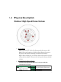
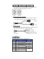
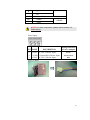
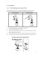
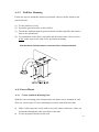
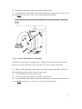
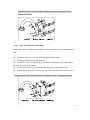
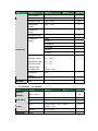
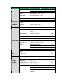
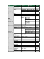
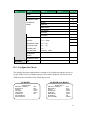
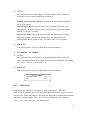
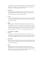
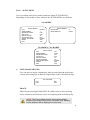
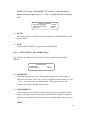
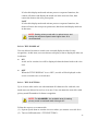
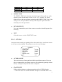
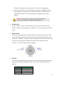
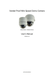
IP Outdoor High Speed Dome
CAM-6600 series
Ver. 070307
Hardware User’s Manual
0
0
1.
2.
PRECAUTIONS
Read these instructions
All the safety and operating instructions should be read before the product is
operated.
Heed all warnings
All warnings on the product and in the instruction manual should be adhered to.
The symbol indicates the following items, please carefully read the
description next to each symbol.
a. Failure to follow the safety instruction given may directly endanger
people, cause damage to the system or to other equipment.
b. The requirements to make this device work, including hardware,
computer settings, network settings, and operation procedures.
c. The tips to make using this device easier, more convenient and more
efficient.
3.
Servicing
Do not attempt to service this video product yourself as opening or removing
covers may expose you to dangerous voltage or other hazards. Refer all servicing
to qualified service personnel.
Copyright
This manual is the intellectual property of ACTi and is protected by copyright. All
rights are reserved. No part of this document maybe reproduced or transmitted for any
purpose by any means including electronic or mechanical without the official written
permission from ACTi.
Trademarks
All names used in this manual for hardware and software are probably registered
trademarks of respective companies.
Liability
Every care has been taken during writing this manual. Please inform your local office
if you find any inaccuracies or omissions. We cannot be held responsible for any
0-1
typographical or technical errors and reserve the right to make changes to the product
and manuals without prior notice.
FCC/CE Regulation
NOTE: This equipment has been tested and found to comply with the limits for a
Class A digital device, pursuant to Part 15 of the FCC Rules. These limits are
designed to provide reasonable protection against harmful interference when the
equipment is operated in a commercial environment. This equipment generates, uses,
and can radiate radio frequency energy and, if not installed and used in accordance
with the instruction manual, may cause harmful interference to radio communications.
Operation of this equipment in a residential area is likely to cause harmful
interference in which case the user will be required to correct the interference at his
own expense.
0-2
Table of Contents
0
PRECAUTIONS________________________________________________ 0-1
Copyright __________________________________________________________________ 0-1
Trademarks ________________________________________________________________ 0-1
Liability ___________________________________________________________________ 0-1
FCC/CE Regulation __________________________________________________________ 0-2
1
INTRODUCTION ________________________________________________1
1.1
Package Contents _________________________________________________ 1
1.2
Features and Benefits ______________________________________________ 2
1.3
Safety Instructions ________________________________________________ 5
1.4
Physical Description _______________________________________________ 7
1.5
Cable Wiring ____________________________________________________ 11
Cable Wiring and Connection ___________________________________________________11
Alarm Cable Wiring___________________________________________________________12
1.6
IP High Speed Dome Setups________________________________________ 13
1.6.1: Prepartions for Dome Setups _______________________________________________13
1.6.2: Dome Setups ___________________________________________________________14
1.7
Basic Connections ________________________________________________ 15
Appendix A: Speed Dome Installation ______________________________________ 16
A-1: Optional Accessories ______________________________________________________16
A-2: Ceiling Mount (Straight Tube) ______________________________________________20
A-3: Wall Mount _____________________________________________________________21
A-3-1
Wall Mounting with Gooseneck Tube______________________________________21
A-3-2
Wall Box Mounting ____________________________________________________22
A-4: Corner Mount ___________________________________________________________22
A-4-1
Corner Standard Mounting Plate __________________________________________22
A-4-2
Corner Thin/Wide Box Mounting _________________________________________23
A-5: Pole Mount _____________________________________________________________24
A-5-1
Pole Thin/Wide Direct Mounting _________________________________________24
A-5-2
Pole Thin/Wide Box Mounting ___________________________________________25
Appendix B: OSD Menu Notes ____________________________________________ 26
B-1: OSD Display Format ______________________________________________________26
0-3
B-2: OSD Setup Menu _________________________________________________________26
B-3: Configuration Menu_______________________________________________________34
B-3-1
DEFAULT CAMERA __________________________________________________35
B-3-2
BACKLIGHT ________________________________________________________35
B-3-3
FOCUS _____________________________________________________________35
B-3-4
APERTURE _________________________________________________________36
B-3-5
AE MODE ___________________________________________________________37
B-3-6
WBC MODE _________________________________________________________39
B-3-7
ID DISPLAY _________________________________________________________40
B-3-8
SETUP MENU _______________________________________________________41
B-3-9
SETUP MENU2 (18x MODEL Only)______________________________________44
B-3-10
TITLE DISPLAY ___________________________________________________45
B-3-11
TITLE SETTING ___________________________________________________45
B-3-12
ALARM SETTING _________________________________________________46
B-3-13
HOME SETTING ___________________________________________________48
B-3-14
SEQENCE ________________________________________________________49
B-3-15
AUTOPAN ________________________________________________________51
B-3-16
CRUISE __________________________________________________________53
B-3-17
IR FUNCTION (Removable IR Cut) ____________________________________54
B-3-18
ALARM DETECT (18x MODEL Only) _________________________________55
B-3-19
WDR SETTING (23x MODEL Only) ___________________________________56
B-3-20
PRIVACY_________________________________________________________57
B-3-21
TIME FUNCTION __________________________________________________60
B-3-22
SCHEDULE FUNCTION ____________________________________________61
B-3-23
EXIT OSD ________________________________________________________62
0-4
11
1.1
INTRODUCTION
Package Contents
CAM-6600 series
Warranty Card
Product CD
Power & A/V Cable
LAN/WAN Cable
Alarm Cable
5.4” Transparent Cover
Power Adaptor (Option)
Lubricant
Screws
1
1.2
Features and Benefits
The IP High Speed Dome is designed to deliver superb performance and
durability with an intelligent and stylish housing. It also provides a realiable
real time images with outstanding image quality (D1, 720x480) at
reasonable bandwidth through a standard TCP/IP network. That’s because it
is Ethernet (LAN and WAN) ready and has a powerful ARM9 SoC and the
MPEG-4 compression ASIC inside. In addition, with these powerful
hardware platform, excellent SDK support and powerful respective
apparatuses (eg. the transcoder or control keyboards), this IP high speed
dome is your best choice building up either conventional IP surveillance
system or intelligent IP surveillance system.
The integrated IP high speed dome provides three models:
22x MODEL: 22x optical zoom multiply 12x digital magnifier
18x MODEL: 18x optical zoom multiply 12x digital magnifier/D&N
23x MODEL: 23x optical zoom multiply 12x digital
magnifier/D&N/WDR
z
Precise and Accurate Tracking
Scheduling function, a special feature, enables users to program a
preset point or function (Sequence/Auto/Cruise) automatically actions
in certain period of time. The IP high speed dome provides vaiable
pan/tilt speed ranging from a fast patrol of 400° per second to a
slow ramble of 5° per second with 0.225° pan accuracy for fast
and accurate tracking ability. The 360° endless rotation and -10
°~190° tilt travel makes tracking the object passing directly
beneath the dome. Maximum 256 preset points can be
programmed for precise location of target areas, and you can
also define 8 sequence, 4 auto-pan and 1 cruise rotes for the
camera to operate automatically.
z
Day/Night Features
IR cut filter removable ensures 24 hours operation (18x MODEL/23x
2
MODEL)
z
Low-Light Application
Digital Slow Shutter and Electronic Shutter functions are provided for
clear and high quality image. The minimum illumination is 0.01 Lux.
z
Perfect Contrast Solution for High Image Quality
Wide Dynamic Range function is a salient features incorporated to fit
your needs (23x MODEL)
z
Privacy Mask for Privacy Protection
There is up to 24 privacy zones of camera view programmable. This is
specially designed to avoid any intrusive monitoring at specific region.
z
Real-time MPEG-4 Compression
With hardware MPEG-4 compression chip inside, the composite video
inputs can be efficiently compressed into MPEG-4 bit stream without
any delay. The ASIC base compression engine can support not only
CIF, but also FULL D1 image resolution.
z
QoS Enabled Video Streaming
For real-time video streaming requirements, the IP high speed dome
implemented the 802.1Q features inside the SoC as the streaming
engine to make sure the video streaming package is forwarded faster
than normal TCP/UDP packet.
z
Automatic Frame Rate Control
The IP high speed dome supports automatic/manual streaming frame
rate control, especially for multiple clients concurrent access the same
video stream in different network bandwidth.
z
Digital Time Code Embedded
The “Digital Time Code Embedded” function is to embed the
recording time in the MPEG bit stream. Therefore, each image frame
has its respective time when it was recorded. It is very useful when
users want to find the video at an exact time or between a certain time
intervals.
z
Build-in LAN and WAN (Low Latency PPPoE Supported) Ports
3
The IP high speed dome provides two RJ-45 connectors. One is WAN
and the other is LAN. The WAN port connects to the internet and LAN
port connects to the local network. Since the internet’s bandwidth is
very critical, the WAN port is equipped with a low latency PPPoE
(Point-to-Point over Ethernet) which has excellent transmission speed
and enables the IP high speed dome to connect to an ADSL or a cable
modem.
z
DDNS Supported
The IP high speed dome supports DDNS (Dynamic Domain Name
Server), users can set the IP high speed dome at a virtual domain name
(such as cam1.Taipei.xxx) at dynamic IP. Everyone can use the virtual
domain name to view the video anywhere that has the access to the
internet.
z
Build-in Hardware Motion Detection
No more external motion sensors are required. Each IP high speed
dome can be set up to 3 detection areas. By tuning the object size and
sensitivity, it is very reliable to fit into your environment. Besides,
hardware motion detection delivers better sensitivity and respond faster
than software motion detection.
z
Bundle Powerful Surveillance Software
To extend the capabilities of the IP high speed dome, a powerful
surveillance program is included in the package and is totally free to
use. Users can easily utilize the existing PC to be a digital video
recorder. Schedule recording and manual recording keep every
important image recorded in the local hard disk. Reliable and accurate
motion detection with instant warning makes you responsive in every
condition. Quick and simple search and playback function lets you
easily find the images you want.
z
Software Development Kit Support
The IP high speed dome can be integrated or controlled by user’s
application program through the Streaming Library or ActiveX control.
With its high level programming interface, software developer’s time
and efforts to is highly reduced.
z
Dynamic Dome Configuration
Flexible indoor/outdoor mountings. You may find a support package
for getting familiar with IP high speed dome’s mounting kits. Please
visit our web site, and get the support package document TS-00004.
4
1.3
Safety Instructions
z
Don’t use the power supply with other voltages
This device is likely to be damaged or damage other equipments /
personnel, if you use a power supply with different voltage than the
one included with this device. All warranty of this product will be
voided in the situations above.
z
Don’t open the housing of the product
z
Cleaning
Disconnect this video product from the power supply before cleaning.
z
Attachments
Do not use attachments not recommended by the video product
manufacturer as they may cause hazards.
z
Water and Moisture
Do not use this video product near water, for example, near a bathtub,
washbowl, kitchen sink, or laundry tub, in a wet basement, or near a
swimming pool and the like.
z
Don’t use accessories not recommended by the manufacturer
z
Only install this device and the power supply in a dry place
protected from weather
z Servicing
Do not attempt to service this video product yourself as opening or
removing covers may expose you to dangerous voltage or other
hazards. Refer all servicing to qualified service personnel.
z
Damage Requiring service
Disconnect this video product from the power supply immediately and
refer servicing to qualified service personnel under the following
conditions.
5
z
1.
When the power-supply cord or plug is damaged.
2.
If liquid has been spilled, or objects have fallen into the video
product.
3.
If the video product has been exposed to rain or water directly.
4.
If the video product does not operate normally by following the
operating Instructions in this manual. Adjust only those controls
that are covered by the instruction manual as an improper
adjustment . Other controls may result in damage and will often
require extensive work by a qualified technician to restore the
video product to its normal operation.
Safety Check
Upon completion of any service or repairs to this video product, ask
the service technician to perform safety checks to determine that the
video product is in proper operating condition.
6
1.4
Physical Description
Outdoor High Speed Dome Bottom
1. Reset Button
Step 1: Switch off IP device by disconnecting the power cable
Step 2: Press and continue to hold the Reset Button. Reconnect
the power cable while continuing to hold the reset button.
Step 3: Keep holding the reset button depressed around 6 seconds,
release the reset button. The unit will start up with factory default
settings.
2. Communication Switch Setting
The table below shows the function of each pin within the
Communication Switch.
Communication Switch
Pin 1
Pin 2
Pin 3
RS-232 Setting (Reserved)
Termination
7
Pin 4
Line Lock
Pin 5
System Initialization (for
upgrade)
Pin 6
Reserved
RS-232 is reserved for internal use only; The Pin 3 and Pin 4, they
are used for termination and Link Lock adjustment respectively.
The Pin 5 is mainly used for return to factory default of camera
setting.
3. Dome ID Setting
Use the switch to change your speed dome ID by turning the
arrow to the desired number respectively. For instance, if the
speed dome ID is 123, the ID switch should be set as below:
centesimal
decimal
single digit
NOTE: No two speed domes should be given the same ID, or
communication conflict may occur.
d
o
NOTE: The number “0” should locate upwards as shown in
above diagram for correct switch definition.
4. Dome Control Protocol
Protocol is a specific set of rules, procdures used for data
communications. Basing on the protocol of your management
software that you are going to use. Use the switch to set your
dome control protocol and the baud rate. Refer to table below and
turn the arrow to choose a protocol for your speed dome.
Switch No.
Protocol
Baud Rate
01
Pelco D
2400
02
Pelco P
4800
07
Dynacolor
9600
11
Pelco D
4800
12
Pelco D
9600
13
Pelco P
2400
8
Pelco P
14
9600
Select protocol: Pelco D, with switch no. 01 and baud rate 2400,
for instance, the ID switch should be set as below:
decimal
single digit
5. 16 Pin Connector for LAN/WAN
The LAN/WAN cable (shown as the figure below) is shipped
with IP high speed dome. Please find it in the accessory bag.
6. 22 Pin Connector
A 50cm data cable (shown as the figure below) is shipped with IP
high speed dome. Please find it in the accessory bag.
The 22-pin connector definition is listed as below.
No.
Pin
Cable
1
AC 24-1/DC GND
2
Alarm Pin (Not wired)
3
AC 24-2/DC 12(+)
4
Alarm Pin (Not wired)
5
FG
6
Alarm Pin (Not wired)
7
T+
8
R-
20AWG
20AWG
20AWG
24AWG
9
9
T-
10
R+
11~20
Alarm Pin (Not wired)
21
VGND
22
Video
P
24AWG
NOTE: For alarm connection, please refer to section 1.5
Cable Wiring.
Power Input
PIN NAME
1
2
3
DESCRIPTION
AC24V AC 24V of Power Input
E-GND E-Ground Pin of Power Input
AC24V AC 24V of Power Input
Wiring Indication
of Power Adapter
Brown
Green/Yellow
Blue
Power Adpater
10
1.5 Cable Wiring
Cable Wiring and Connection
Users may need to do cable wiring when connecting alarm input and
output devices. The table follows will illustrate the way to wire cords
into the connector housing (shown in the figures below).
Insert the terminal into the pin
holes on the connector
housing, with the hook
outward, as indicated in the
figure.
To unlock the terminal, press
the hook, as indicated in the
figure, with a proper tool and
pull it out gently.
11
Alarm Cable Wiring
The alarm pins are serviceable for connecting alarm input and output
devices, such as alarm sensors, sirens or flashing lights with the
surveillance system. The table shown as follows lists the definition of
alarm pins on the 22-pin connector.
Pin
Definition
2
ALM NC
4
ALM NO
6
ALM COM
11
ISOG
12
ALM-1
13
ALM-3
14
ALM-2
15
ALM-4
16
ALM-5
17
ALM-6
18
ALM-7
19
ALM-8
20
ALM GND
12
1.6 IP High Speed Dome Setups
Before installing or connecting the speed dome camera, please refer to this section
and complete preparation, switch setting and communication switch settings.
1.6.1: Prepartions for Dome Setups
The section will illustrate the speed dome housing installation procedure of the
outdoor speed dome equipped with sunshield. Please follow the steps below to
complete speed dome housing installation.
STEP 1
Unpack the dome package and take
out the dome body.
STEP 2
Rotate the top holder and take it
off from the dome body.
STEP 3
Set the dome on a flat table to keep
it stable and then remove the
protective cover and PE cloth.
STEP 4
Attach the dome cover to the dome
body. Before doing that, apply
some
lubricant
on
the
dome
cover’s water-proof rubber to make
the installation process smoother.
13
Note that the tiny protrusion on the
dome cover must align with one of
the four holes on the dome body.
STEP 5
Assemble the dome cover to the
dome body by pressing the cover
gently downward to the dome body
with two hands on the side of the
cover.
DO NOT press the cover as shown
in the figure; this might cause
damage to the dome body.
STEP 6
Screw the dome cover and body
together.
1.6.2: Dome Setups
Before connecting the speed dome camera to other devices of CCTV system, please
complete the speed dome ID and communication switch settings. These switches are
located on the bottom of the speed dome camera (refer to section 1.4 Physical
Description).
14
1.7 Basic Connections
Follow the procedures below to connect the IP high speed dome to the respective
apparatuses.
15
Appendix A: Speed Dome Installation
Basing on user’s installation environments, the dome can be installed on ceiling, on
wall or on pole. In the following section, various outdoor speed dome installation
accessories, installation methods and installation procedures will be described in
detail.
A-1: Optional Accessories
Mounting Accessories
Gooseneck Tube
White; 298×385 mm (11.73×15.56 inches) ; 2.1 kg (4.6 lbs)
Supplied with rubber washer-8×1, pendant tube washer×1, spring washer-8×1 and waterproof
rubber×1, M8*12 screw×1.
Straight Tube
White; Height: 250/500 mm (9.8/19.7 inches); Diameter: 50 mm (2 inches)
1 kg (2.2 lbs) / 1.8 kg (4 lbs). Supplied with rubber washer-8×1, pendant tube washer×1, spring
washer-8×1 and waterproof rubber×1, M8*12 screw×1.
16
Corner Standard Mounting Plate
White; 222(L)×204(W)×117(D) mm (8.7×8×4.6 inches); 2 kg (4.4 lbs). Supplied with
washer-8×4, spring washer×4, M8*20 screw×4, M8 nut×4.
Pole Thin Direct Mounting
White; 232(L)×136(W)×60(D) mm (9.1×5.4×2.4 inches); Diameter: 112~140 mm (4.4~5.5
inches); 0.7 kg (1.6 lbs). Supplied with stainless steel straps×4, M8*16 screw×4, washer×4.
17
Corner Thin Box
White, 300(L)×164(W)×222(D) mm (11.8×6.5×8.7 inches); 3 kg (6.7 lbs); Supplied with
washer×4, M8*16 screw×4 and spring washer×4.
Pole Thin Box
White; 291(L)×136(W)×245(D) mm (11.5×5.3×9.5 inches); 3.1 kg (6.9 lbs); Supplied with
M8*16 screw×4, washer×4, spring washer×4, stainless steel straps×4.
Wall Box Mounting
White, 270(L)×166(W)×95(D) (10.6×6.5×3.7 inches); 2.2 kg (4.84 lbs); Supplied with M8*16
screw×4, washer×4, spring washer×4
18
Stainless Steel Straps
For fixing Pole Direct Mounting/ Pole Box on the pole.
Width: 0.63”; 0.02 kg (0.04 lbs)
Stainless Strap Cutter
For tension, cut and crimp stainless steel straps. 1.4 kg (3.1 lbs)
Suitable for straps width: 1/2”, 5/8”, 3/4”
Other Application Accessories
Power Box
White; 186.5×147 mm (7.3×5.8 inches); 2.6 kg (5.8 lbs)
Input: 110~115VAC/Output: 24VAC 72VA
Input: 220~230VAC/Output: 24VAC 72VA
19
A-2: Ceiling Mount (Straight Tube)
Follow the steps to mount the speed dome camera with the straight tube.
(1) Ensure that the ceiling can support the weight of the speed dome camera and
straight tube.
(2) Make a cable entry hole on the ceiling.
(3) Fix the suspension bracket to the ceiling.
(4) Thread the cables through the straight tube and the top holder and connect them to
the speed dome camera.
(5) Fix the top holder to the straight tube using the screws and washers.
(6) Attach the speed dome camera to top holder and fix them with the screw.
Ceiling Mount: Straight Tube + Waterproof Rubber
20
A-3: Wall Mount
A-3-1
Wall Mounting with Gooseneck Tube
The following figures show how cables run through the tube in different ways.
Follow the steps to mount the speed dome camera with the gooseneck tube.
Cables exposed
(1)
(2)
(3)
(4)
(5)
Cables recessed
Make a cable entry hole on the wall to recess the cables. Otherwise, cables can
be threaded through the cable entry hole on the tube.
Fix the suspension bracket to the wall.
Thread the cables through the gooseneck tube and the top holder and connect
them to the speed dome camera.
Fix the top holder to gooseneck tube using the equipped screws and washers.
Attach the speed dome camera to the top holder and fix them with the screw.
Wall Mount: Gooseneck Tube + Waterproof Rubber
21
A-3-2
Wall Box Mounting
Follow the steps to mount the outdoor speed dome camera with the wall box and
gooseneck tube.
(1) Fix the wall box to wall.
(2) Fasten the gooseneck tube on the wall box.
(3) Thread the cables through the gooseneck tube and the top holder and connect
them to the speed dome.
(4) For installation of the cables, top holder and the camera unit, refer to section
A-3-1 as the steps are the same as for gooseneck mounting.
Wall Box Mount: Wall Box Mount + Gooseneck Tube + Waterproof Rubber
A-4: Corner Mount
A-4-1
Corner Standard Mounting Plate
With the corner mounting plate and gooseneck, the dome can be mounted on wall.
There are various types of corner mounting accessories with different width.
1)
2)
Make a cable entry hole on the wall to recess the cables. Otherwise, cables can
be threaded through the cable entry hole on the tube
Fix the suspension bracket on the wall
22
3) Attache the gooseneck tube to the firmly fixed bracket
4) For installation of the cables, top holder and the speed dome camera unit, refer to
section A-3-1 as the steps are the same as for gooseneck mounting.
Corner Wall Mount: Corner Standard Mounting Plate + Gooseneck Tube + Waterproof
Rubber
A-4-2
Corner Thin/Wide Box Mounting
The thin/wide corner box is designed to be installed with a gooseneck tube. Follow
the steps to mount the dome camera with the corner box and gooseneck tube.
1) Make a cable entry hole on the wall to recess the cables. Otherwise, cables can
be threaded through the cable entry hole on the tube
2) Fix the suspension bracket on the wall
3) Attache the gooseneck tube to the firmly fixed bracket
4) For installation of the cables, top holder and the speed dome camera unit, refer to
section A-3-1 as the steps are the same as for gooseneck mounting.
23
Corner Box Mounting: Corner Thin/Wide Box + Gooseneck Tube + Waterproof Rubber
A-5: Pole Mount
A-5-1
Pole Thin/Wide Direct Mounting
The dome can be installed on a pole with a thin or wide pole mounting accessory and
a gooseneck.
1)
2)
3)
4)
Fasten the suspension mounting plate on a pole with equipped stainless straps
Fix the gooseneck tube on the pole mounting plate
Thread the cables through the gooseneck tube and the top holder and connect
them to the speed dome camera
For installation of the cables, top holder and the speed dome camera unit, refer to
section A-3-1 as the steps are the same as for gooseneck mounting.
24
Pole Direct Mount: Pole Thin/Wide Direct Mounting +Gooseneck Tube +
Waterproof Rubber
A-5-2
Pole Thin/Wide Box Mounting
Follow the steps to mount the speed dome camera with the pole box and gooseneck
tube.
1) Fasten the pole box on a pole with equipped stainless straps
2) Fix the gooseneck tube to the pole box
3) Thread the cables through the gooseneck tube and the top holder and connect
them to the speed dome camera
4) Fix the top holder to the gooseneck tube using the screws and washers.
5) Attache the speed dome camera to the top holder and fix them with the screw.
Pole Box Mount: Pole Thin/Wide Box + Gooseneck Tube + Waterproof Rubber
25
Appendix B: OSD Menu Notes
B-1: OSD Display Format
The information shown on the screen are described in terms of OSD display,
position and function description in the table below.
1
3
2
4
6
5
Position
Function
1
Focus Modes
2
Backlight
3
Alarm
4
Zoom Ratio
5
Title
6
Camera ID
OSD Display
A
M
X
B
ALARM
Description
Auto Focus Mode
Manual Focus Mode
Back Light Compensation OFF
Back Light Compensation ON
Alarm Message
Present Zoom Ratio
×1
(Optical Zoom(Digital Zoom)
• Maximum 20 characters for each title.
• 16 sets of title are available.
Show the camera ID
B-2: OSD Setup Menu
The OSD setup menu structure of 18x model and 22x model/23x model are listed
separately in the following section. The star symbol indicates the factory default.
For detailed function description, please see section B-3 Configuration Menu
26
¾
18x MODEL
Item
DEFAULT
CAMERA
BACKLIGHT
Layer 1
Layer 3
Default
<ON>, <OFF>
ON
<ON>, <OFF>
OFF
AUTO
AF Mode <Normal>, <Interval>,
Normal
<Zoom Trigger>
FOCUS
AE MODE
Layer 2
MANUAL
Focus Manual Speed <01>~<08>
AUTO
Exposure Comp. <OFF>, <1>~<15>
BRIGHT
Bright <0> ~ <31>
SHUTTER
Shutter Speed <1> ~ <1/10000> Sec.
GAIN
Gain <-3> ~ <28>dB
IRIS
Iris <Close>, <F1.6> ~ <F28>
AUTO (Auto White Balance)
OFF
☆
INDOOR
WBC MODE
OUTDOOR
ATW (Auto-tracing WBC)
MANUAL
R Gain <000> ~ <128>
B Gain <000> ~ <128>
ID DISPLAY
SETUP MENU
1
<ON>, <OFF>
ON
FLIP
<IMAGE>, <M.E.>, <OFF>
OFF
ZOOM SPEED
<1> ~ <8>
SPEED BY ZOOM
<ON>, <OFF>
OFF
AUTO CALI.
<ON>, <OFF>
OFF
DIGITAL ZOOM
<ON>, <OFF>
ON
SLOW SHUTTER
<ON>, <OFF>
OFF
ANGLE
ADJUST MIN ANGLE
00
ADJUSTER
ADJUST MAX ANGLE
90
8
RESET
RESET
<YES>
EXIT
SETUP MENU
APERTURE
<01> ~ <16>
2
MASK DISPLAY
<FIRST>, <LAST>
TITLE
<ON>, <OFF>
01
First
OFF
DISPLAY
TITLE
<01> ~ <16>
01
27
Item
Layer 1
Layer 2
Layer 3
Default
ALARM PIN
<1> ~ <8>
ALARM SWITCH
<ON>, <OFF>
OFF
ALARM TYPE
<N.O.> (Normal Open), <N.C.>
N.C.
SETTING
1
(Normal Close)
ALARM ACTION
PRESET
☆
SEQUENCE
ALARM
AUTOPAN
SETTNG
CRUISE
PRESET POINT
<001> ~ <256>
SEQUENCE LINE
<1> ~ <8>
AUTOPAN LINE
<1> ~ <4>
CRUISE LINE
<1>
DWELL TIME
<001> ~ <127> Sec., <ALWAYS>
EXIT
YES
HOME FUNC.
<ON>, <OFF>
SELECT MODE
PRESET
001
ALWAYS
OFF
☆
SEQUENCE
AUTOPAN
CRUISE
HOME
PRESET POINT
<001> ~ <256>
SETTING
SEQUENCE LINE
<1> ~ <8>
AUTOPAN LINE
<1> ~ <4>
CRUISE LINE
<1>
RETURN TIME
<001> ~ <128> Min.
GO
ENTER
001
001
EXIT
SEQUENCE LINE
<1> ~ <8>
1
SEQUENCE
<01> ~ <32>
01
PRESET POS.
<001> ~ <256>
001
SPEED
<01> ~ <15>
01
DWELL TIME
<000> ~ <127> Sec.
000
POINT
SEQUENCE
RUN SEQUNECE
EXIT
28
Item
AUTOPAN
Layer 1
Layer 2
Layer 3
AUTOPAN LINE
<1> ~ <4>
START POINT
<TO FIND>, <TO SAVE>
END POINT
<TO FIND>, <TO SAVE>
DIRECTION
<RIGHT>, <LEFT>
SPEED
<01> ~ <04>
Default
1
Right
01
RUN AUTOPAN
EXIT
RECORD START
RECORD END
CRUISE
RUN CRUISE
EXIT
IR FUNCTION
(F/U
model
<AUTO>, <ON>
Auto
only)
ALARM
DETECT SWITCH
<ON>, <OFF>
DETECT MODE
<INT. FOCUS>, <FIX FOCUS>, <INT.
DETECT
OFF
AE>, <FIX AE>
Int. Focus
EXIT
PRIVACY
<ON>, <OFF>
OFF
TRANSPARENCY
<ON>, <OFF>
OFF
COLOR
<BLACK>, <HEAVY GRAY>, <LIGHT
Black
SWITCH
GRAY>, <WHITE>, <RED>,
<GREEN>, <BLUE>, <CYAN>,
PRIVACY
<YELLOW>, <MAGENTA>
SET MASK
<01> ~ <24>
H CENTER <L>, <R>
V CENTER <D>, <U>
H SIZE <00> ~ <80>
V SIZE <00> ~ <60>
TIME
EXIT
YES
TIME DISPLAY
<ON>, <OFF>
OFF
SET YEAR
SET MONTH
SET DAY
SET HOUR
29
Item
Layer 1
Layer 2
Layer 3
Default
SET MINUTE
EXIT+SAVE
SCHEDULE SW.
<ON>, <OFF>
SCHEDULE
<01> ~ <32>
OFF
01
POINT
SCHEDULE
00
HOUR
SCHEDULE MIN
00
SCHEDULE
NONE
MODE
PRESET
☆
SEQUENCE
AUTOPAN
SCHEDULE
CRUISE
IR FUNC.
NO FUNCTION
PRESET POINT
<1> ~ <256>
SEQUENCE LINE
<1> ~ <8>
AUTOPAN LINE
<1> ~ <4>
CRUISE LINE
<1>
IR FUNCTION
<AUTO>,<ON>
SCHEDULE
YES
RESET
SCHEDULE EXIT
EXIT OSD
¾
YES
22x MODEL / 23x MODEL
Item
DEFAULT
CAMERA
BACKLIGHT
Layer 1
Layer 2
Layer 3
<ON>, <OFF>
ON
ON
BLC Level <000> ~ <100>
☆
OFF
AUTO
Focus Length <1cm>, <10cm>,
10 cm
<30cm> <1m>
FOCUS
MANUAL
APERTURE
Default
AUTO
<01> ~ <08>
☆
30
Item
Layer 1
Layer 2
Layer 3
MANUAL
H APERTURE <00> ~ <31>
Default
V APERTURE <00> ~ <31>
AUTO
IRIS OFFSET <00> ~ <99>
SHUTTER
SHUTTER SPEED <1/2> ~
<1/30000>
AE MODE
IRIS
IRIS <00> ~ <09>
AGC
AGC <00> ~ <05>
☆
AUTO
WBC MODE
50
MANUAL
R Gain <00> ~ <99>
B Gain <00> ~ <99>
ID DISPLAY
<ON>, <OFF>
FLIP
ON
<IMAGE>(K model only), <M.E.>,
OFF
<OFF>
SETUP MENU
ZOOM SPEED
<FAST>, <SLOW>
Slow
SPEED BY ZOOM
<ON>, <OFF>
OFF
AUTO CALI.
<ON>, <OFF>
OFF
DIGITAL ZOOM
<1> ~ <12>, <OFF>
OFF
SLOW SHUTTER
<1/2> ~ <1/60> Sec. (NTSC)
1/30
(K model only)
<1/1.5> ~ <1/50> Sec. (PAL)
ANGLE
ADJUST MIN ANGLE
00
ADJUSTER
ADJUST MAX ANGLE
90
RESET
RESET
YES
EXIT
TITLE
<ON>, <OFF>
OFF
DISPLAY
TITLE
<01> ~ <16>
01
SETTING
ALARM
ALARM PIN
<1> ~ <8>
1
SETTNG
ALARM SWITCH
<ON>, <OFF>
OFF
ALARM TYPE
<N.O.>, <N.C.>
N.C.
ALARM ACTION
PRESET
☆
SEQUENCE
AUTOPAN
CRUISE
31
Item
Layer 1
Layer 2
Layer 3
PRESET POINT
<001> ~ <256>
SEQUENCE LINE
<1> ~ <8>
AUTOPAN LINE
<1> ~ <4>
CRUISE LINE
<1>
DWELL TIME
<001> ~ <127> Sec., ALWAYS
EXIT
YES
HOME FUNC.
<ON>, <OFF>
SELECT MODE
PRESET
Default
001
ALWAYS
OFF
☆
SEQUENCE
AUTOPAN
CRUISE
HOME
PRESET POINT
<001> ~ <256>
SETTING
SEQUENCE LINE
<1> ~ <8>
AUTOPAN LINE
<1> ~ <4>
CRUISE LINE
<1>
RETURN TIME
<001> ~ <128> Min.
GO
ENTER
EXIT
YES
SEQUENCE LINE
<1> ~ <8>
1
SEQUENCE
<01> ~ <32>
01
PRESET POS.
<001> ~ <255>, <END>
001
SPEED
<01> ~ <15>
01
DWELL TIME
<000> ~ <127> Sec.
000
RUN SEQUNECE
ENTER
001
001
POINT
SEQUENCE
EXIT
AUTOPAN
AUTOPAN LINE
<1> ~ <4>
START POINT
<TO FIND>, <TO SAVE>
END POINT
<TO FIND>, <TO SAVE>
DIRECTION
<RIGHT>, <LEFT>
SPEED
<01> ~ <04>
RUN AUTOPAN
ENTER
1
Right
01
EXIT
CRUISE
RECORD START
RECORD END
32
Item
Layer 1
Layer 2
Layer 3
Default
RUN CRUISE
EXIT
AUTO
THRESHOLD
<LOW>, <MID>, <HI>
LOW
IR FUNCTION
IR COLOR
<B/W>, <COLOR>
B/W
(K model only)
EXIT
ON
WDR SWITCH
<ON>, <OFF>
WDR FUNCTION
AUTO
WDR
OFF
☆
MANUA
RATIO LEVEL
L
<000>~<128>
SETTING
SHUTTER LEVEL
(K model only)
<000>~<128>
IRIS OFFSET
<000>~<128>
EXIT
PRIVACY SWITCH
<ON>, <OFF>
OFF
SHADE
<BLACK>, <WHITE>, <GRAY>
Gray
SET MASK
<1> ~
H CENTER <000> ~ <256>
<8>
V CENTER <000> ~ <256>
PRIVACY
H SIZE <000> ~ <127>
(K model only)
V SIZE <000> ~ <127>
MASK
<01> ~< 08>
01
CLEAR+RESET
MASK DSIPLAY
<FIRST>, <LAST>
First
EXIT
YES
TIME DISPLAY
<ON>, <OFF>
OFF
<ON>, <OFF>
OFF
SET YEAR
SET MONTH
TIME
SET DAY
SET HOUR
SET MINUTE
EXIT+SAVE
SCHEDULE
SCHEDULE
SWITCH
SCHEDULE
<01> ~ <32>
01
33
Item
Layer 1
Layer 2
Layer 3
Default
POINT
SCHEDULE HOUR
00
SCHEDULE MIN
00
SCHEDULE
NONE
MODE
PRESET
☆
SEQUENCE
AUTOPAN
CRUISE
IR FUNC.
NO FUNCTION
PRESET
<1> ~ <256>
SEQUENCE LINE
<1> ~ <8>
AUTOPAN LINE
<1> ~ <4>
CRUISE LINE
<1>
IR FUNCTION
<AUTO>, <ON>
SCHEDULE
RESET
SCHEDULE EXIT
EXIT OSD
YES
B-3: Configuration Menu
The detailed functions and parameter settings of your high speed dome can be set
by the OSD (On Screen Display) menu with a control program. The functions in
OSD menu are described in the following sections.
18x MODEL
MAIN PAGE 1
DEFAULT CAMERA
BACKLIGHT
FOCUS
AE MODE
WBC MODE
ID DISPLAY
SETUP MENU1
SETUP MENU2
22x MODEL/23x MODEL
OFF
OFF
AUTO
AUTO
AUTO
ON
MAIN PAGE 1
DEFAULT CAMERA
BACKLIGHT
FOCUS
APERTURE
AE MODE
WBC MODE
ID DISPLAY
SETUP MENU
OFF
OFF
AUTO
AUTO
AUTO
AUTO
ON
ENTER
34
B-3-1
DEFAULT CAMERA
The “DEFAULT CAMERA” is used to restore the camera settings (e.g.
Backlight/Focus/AE//WBC/Aperture). Once any one of the items is modified, the
setting will become <OFF> automatically. Select <ON> for this item to recall the
mentioned camera parameters.
NOTE: On 18x MODEL, the Aperture function is provided in
“SETUP MENU2”, instead of “DEFAULT CAMERA”.
B-3-2
BACKLIGHT
The Backlight compensation function prevents the center object from being too
dark in surroundings where excessive light is behind the center object.
¾ 18x MODEL
Turn this item <ON>; the center object will be brightened in contrast to the edge
of the picture (where a backlight would most likely be located).
¾ 22x MODEL / 23x MODEL
The Backlight Compensation Level ranges from 000 to 100.
BLC LEVEL
LEVEL
EXIT
20
YES
NOTE: If this function is enabled, the WDR function (for 23x
MODEL only) will be disabled automatically. For details, refer
to section B-3-19 WDR Setting.
B-3-3
FOCUS
Automatically adjusts the focus position to maximize the high frequency content
of the picture in a center measurement area, taking into consideration the high
luminance and strong contrast components. The focus of the dome camera can be
operated in two modes: Manual Focus mode and Auto Focus mode. Different
settings for various models are described as follows.
¾
18x MODEL
35
♦
AUTO
The optimum focus is achieved by the internal digital circuit. There are 3
modes for users to select for different conditions.
Normal AF (Auto Focus) Mode: The dome will automatically adjust the
focus of the picture.
Zoom Trigger Mode: When the zoom ratio is changed, the dome will
automatically adjust focus again after a period of time (the preset value is
initially set for five seconds).
Interval AF Mode: The mode is used for AF movements carried out at
particular intervals. If users pan/tilt the dome, the dome will focus
automatically after a period of time. The initial value is five seconds.
♦
MANUAL
In this focus mode, users can adjust the lens focus manually.
¾
♦
22x MODEL / 23x MODEL
AUTO
The optimum focus is achieved by the internal digital circuit. Users can
adjust the minimum auto focus range for some special conditions; the options
are <1cm>, <10cm>, <30cm> and <1m>.
♦
MANUAL
In this focus mode, users can adjust the lens focus manually.
FOCUS LENGTH
TURNING VALUE
10CM
EXIT
YES
B-3-4
APERTURE
Sharpness is the subjective evaluation of detail in the picture. With this
“APEATURE” function, users can adjust the enhancement of the edges of objects
in the picture. When shooting text, this function may help by making them sharper
and achieve a better image. There are 32 levels of adjustment, the options are
<00> ~ <31>, <00> represents “no enhancement”.
36
♦ AUTO
The dome camera will assign a proper aperture value automatically for camera to
achieve a better image.
♦
MANUAL
Select this item if you want to adjust aperture value manually. Higher value
enhances the incident ray of camera.
APERTURE MENU
H APERTURE
15
V APERTURE
15
NOTE: For 18x MODEL, please refer to section B-3-9
SETUP MENU2 for information on Aperture function.
B-3-5
AE MODE
The exposure is the amount of light received by the image sensor and is
determined by how wide you open the lens diaphragm (iris adjustment), by
how long you keep the sensor exposed (shutter speed), and other exposure
parameters. With this item, users can define how the Auto Exposure (AE)
function works.
¾
♦
18x MODEL
AUTO
In this mode, the camera’s IRIS and AGC (Auto Gain Control) control
circuits work together automatically to adjust the light exposure of image
sensor in order to get consistent video output level. At this condition the
shutter speed is fixed at 1/60 (NTSC) or 1/50(PAL). Users can offset the
internal brightness reference level through auto Exposure Comp. to control
the brightness of camera. The value of Exposure Comp. is selectable from
<0> to <16> and the gain varies from -10.5 dB to 10.5 dB. Each step is 1.5
dB; the Exposure Comp. vaue <7> is equal to gain value 0 dB. The camera
will not compensate brightness when the Exposure Comp. is set to <OFF>.
The default setting is <OFF>.
♦
BRIGHT
37
The brightness control function adjusts IRIS and AGC gain using an internal
algorithm. The brightness is controlled by gain when the light condition is
dark and by iris when the light condition is bright.
♦
SHUTTER
With this option, the SHUTTER speed takes main control of the exposure,
and both IRIS and AGC will function automatically in cooperation with
shutter speed to achieve consistent exposure output.
♦
GAIN
The auto GAIN control function takes main control of exposure with priority
over SHUTTER and IRIS. The internal circuit will function automatically to
get consistent exposure.
♦
IRIS
With this option, the IRIS function adjust the exposure in higher property.
SHUTTER speed and AGC circuit will function automatically in cooperating
with IRIS to get consistent exposure output. The opening of a lens controls
the amount of light reaching the surface of the selected device. By increasing
the F-stop number (F/1.6, F/2, F/2.4, etc.), less light is permitted to pass.
¾
♦
22x MODEL / 23x MODEL
AUTO
In this mode, the camera’s Shutter, IRIS and AGC control function work
automatically to compensate the light exposure of image sensor for consistent
video output level. IRIS OFF SET is used to set the level of IRIS variation.
♦
SHUTTER
With this option, the SHUTTER priority is higher than IRIS and AGC; IRIS
and AGC circuit will function automatically in cooperating with SHUTTER
to get consistent exposure.
♦
IRIS
With this option, the IRIS priority is higher than SHUTTER and AGC;
SHUTTER and AGC circuit will function automatically in cooperating with
IRIS to get consistent exposure. If the IRIS is modified manually, the action
of exposure compensation depends on the AGC circuit.
38
♦
AGC
With this option, the AGC priority is higher than SHUTTER and IRIS;
SHUTTER and IRIS circuit will function automatically in cooperating with
AGC to get consistent exposure. If AGC is adjusted manuall, the exposure
compensation depends on the changing of IRIS.
B-3-6
WBC MODE
A digital camera needs to find reference colour temperature, which is a way of
measuring the quality of a light source, for calculating all the other colours. The
unit for measuring this ratio is in degree Kelvin (K). You can select one of the
White Balance Control modes according to the condition. The following table
shows the colour temperature of some light sources.
Light Sources
Cloudy Sky
Noon Sun and Clear Sky
Household Lighting
75-watt Bulb
Candle Flame
Color Temperature in K
6,000 to 8,000
6,500
2,500 to 3,000
2,820
1,200 to 1,500
¾
♦
18x MODEL
AUTO
In this mode, white balance works within its colour temperature range. This
mode computes the white balance value output using colour information
from the entire screen. It outputs the proper value using the colour
temperature radiating from a black subject based on a range of values from
3000K to 7500K.
♦
INDOOR
3200K Base mode
♦
OUTDOOR
5800K Base mode
♦
ATW
39
Auto Tracing White Balance mode. The dome taking out the signals in a
screen in the range from 2000K to 10000K.
♦
MANUAL
In this mode, users can change the White Balance value manually; R gain
and B gain are adjustable and range from 0 to 128.
WBC MENU
R GAIN
B GAIN
50
50
¾
♦
22x MODEL / 23x MODEL
AUTO
In this mode, white balance works within its colour temperature range and
calculates the best-fit white balance.
♦
MANUAL
In this mode, users can change the White Balance value manually; adjustable
R gain and B gain range from 0 to 99.
WBC MENU
R GAIN
B GAIN
B-3-7
50
50
ID DISPLAY
Users are allowed to choose whether the dome ID will be displayed on monitor to
identify the domes.
♦
ON
Display the ID address of the selected dome on the right bottom of the
monitor screen.
♦
OFF
Hide the ID address of the selected dome.
40
B-3-8
SETUP MENU
Users can adjust camera lens model parameters under SETUP MENUs.
Depending on the model of dome cameras, the SETUP MENUs are different.
18x MODEL
SETUP MENU1
FLIP
ZOOM SPEED
SPEED BY ZOOM
AUTO CALI.
DIGITAL ZOOM
SLOW SHUTTER
ANGLE ADJUSTER
RESET
EXIT
ENTER
1
OFF
OFF
12
OFF
ENTER
YES
YES
SETUP MENU2
APERTURE
MASK DISPLAY
01
FIRST
22x MODEL / 23x MODEL
SETUP PAGE
FLIP
ZOOM SPEED
SPEED BY ZOOM
AUTO CALI.
DIGITAL ZOOM
SLOW SHUTTER
ANGLE ADJUSTER
RESET
EXIT
♦
ON
FAST
ON
OFF
12
1/2
ENTER
YES
YES
FLIP (IMAGE/ME/OFF)
User can track an object continuously when it passes through under dome
camera with setting Flip to IMAGE (digital flip) or M.E. (mechanical flip).
FLIP SETTING
FLIP
EXIT
OFF
YES
IMAGE
IMAGE represents digital IMAGE FLIP, enables users to keep tracking
object seamlessly and no delay occurs in comparing with mechanical flip.
NOTE: The Privacy Mask function will be automatically
disabled if the Image Flip function is enabled, and “Masking
will be disabled” will be displayed on the screen.
41
M.E.
The item is a standard mechanical operation. As the dome tilts 90°, it will
pan 180°, then continuing tilt to keep tracking object.
OFF
Select this item to disable the flip function.
NOTE: The speed dome will only be able to tilt 90°, or -10°
~ 100° with angle adjuster adjustments.
♦
ZOOM SPEED
This item is used to set the zoom speed for operating the dome camera.
¾
18x MODEL
For this model, the zoom speed options are <1> (slow) ~ <8> (fast). The
default is <8>
¾
22x MODEL / 23x MODEL
For these two models, the options are <FAST> and <SLOW> (default).
♦
SPEED BY ZOOM
If the item is set to <ON>, the pan/tilt speed will be adjusted by internal
algorithm when zooming automatically. The larger zoom ratio leads the
lower rotation speed.
♦
AUTO CALIBRATION
There are one horizontal and one vertical infrared rays check points in each
dome. When the dome camera position may be moved during installation or
maintenance, the relative distance between the original set point and the
check point has been changed. Enable the Auto Calibration function, the
dome will automatically detect that and reset the point baack to the original
position.
♦
DIGITAL ZOOM
42
With this item, users can enable or disable the 12x Digital Zoom. The Digital
Zoom activate after the full Optical Zoom level is reached.
NOTE: The difference between optical and digital zoom is
that optical zoom uses the lens within the camera to draw the
image closer via zoom in or out to achieve the desired effect.
Optical zoom remains the same and the full resolution of the
zoomed image quality. On the other hand, Digital zoom takes
a portion of image and expands that image to the full size of
the image; however the image quality will be reduced.
¾
18x MODEL
For this model, maximum 12x digital zoom function is allowed to be enabled.
The default setting is <ON>
¾
22x MODEL / 23x MODEL
For these two models, Digital zoom ration is adjustable from <1> to <12>.
♦
SLOW SHUTTER
The shutter speed determines how long the image sensor is exposed to light.
To see clear image in a dark environment, enable this function and select a
slower shutter speed.
¾
18x MODEL
As enable this digital slow shutter function, the dome will automatically
adjust the shutter speed basing on the light condition of installation
environment. It enables users to see objects in a dark environment under 0.2
lux.
¾
23x MODEL
The shutter speed is adjustable on 23x MODEL. With the slowest shutter
speed, users can see objects in a dark environment under 0.2 lux; or see a
smooth video image with a higher shutter speed. The options are from <1/2>
to <1/60>.
♦
ANGLE ADJUSTER
The item is for adjusting the camera view angle. The ranges of view angle
are changed in different FLIP mode: the angle ranges from -10° to +100°
with ME FLIP and FLIP OFF modes, and from -10° ~ +190° with
43
IMAGE FLIP mode. With IMAGE FLIP function, users are able to
adjust the view angle from -10° ~ +190° to catch the true horizontal
line.
ANGLE ADJUSTER
ADJUST MIN ANGLE
-10 DEG
ADJUST MAX ANGLE
100 DEG
EXIT+SET
YES
♦
RESET
Select this item to reset all the camera parameters of SETUP MENUs to the
factory dfault.
♦
EXIT
Exit the SETUP MENU1 and go back to MAN MENU.
B-3-9
SETUP MENU2 (18x MODEL Only)
The Aperture and Mask Display settings can be configured under SETUP
MENU2.
SETUP MENU2
APERTURE
MASK DISPLAY
01
FIRST
♦
APERTURE
Under this setup menu, users can adjust the enhancement of the edges of
objects in the picture. There are 16 levels of adjustment; the options are <01)
~ <16>, <01> represents “no enhancement”. When shooting text, this
function may help by making them sharper.
♦
MASK DISPLAY
In this item, users can set the occasion to display the Privacy Mask, which
aims to avoid any intrusive monitoring. If preset point function or sequence
function is activated, the difference of the two display mode will be obvious.
FIRST
44
If select this display mode and activate preset or sequence functions, the
camera will detect and display the masks set in the next area first, then
rotates the dome to the next preset point.
LAST
If select this display mode and activate preset or sequence functions, the
dome will move the next preset point zone, then detect and display mask set
in that zone.
NOTE: Setting privacy mask with 1x optical zoom, and
setting the sequence speed value higher than 10 is
recommended.
B-3-10 TITLE DISPLAY
User are allowed to name a certain view area and display its title for easy
recognition. At this item, users can choose to display or not to display the titles set
in advance.
♦
ON
A title set for certain view will be displayed when the dome back to the view
area.
♦
OFF
When the TITLE DISPLAY is set <OFF>, no title will be displayed on the
screen even titles are set in advance.
B-3-11 TITLE SETTING
Up to 16 zone titles can be set with maximum 20 characters for each title; two
mask zones are allowed to set in a view area. Users can name the zone titles with
privacy mask ID numbers for future recognition.
NOTE: For 23x MODEL, the available area for setting
privacy mask is restricted within tilt angle 45°.
Follow the steps to set a camera title.
(1) Operate speed dome to certain view area where you want to set a title for it.
(2) Turn on OSD and select <TITLE SETTING>.
45
(3) Select a number to indicate the view area.
(4) Press <ENTER> to go into editing mode.
TITLE SETTING: 01
0
A
K
U
[
1
B
L
V
]
2
C
M
W
+
3
D
N
X
?
4
E
O
Y
-
5
F
P
Z
6
G
Q
:
7
H
R
/
8
I
S
.
9
J
T
,
EXIT
SAVE
LEFT
RIGHT
DELETE
TITLE:
ABC
(5) Choose a character with direction keys and then press <ENTER> to input.
Example: <A> <ENTER>, <B> <ENTER>, <C> <ENTER>
TITLE: ABC
(6) To delete entered characters, move the cursor to <LEFT> or <RIGHT> and press
<ENTER> to select a character in entry field, then move the cursor to
<DELETE> and press <ENTER> to delete the selected character.
(7) When the setting is completed, move the cursor to <SAVE> and press
<ENTER> to save.
B-3-12 ALARM SETTING
The integrated high speed dome provides eight alarm inputs and two alarm
outputs (N.O. and N.C.) to connect alarm devices. With this function, dome will
cooperates with alarm system to catch the event images. For wiring, please refer
to the installation guide and/or qualified service personnel. Alarm parameters can
be set on this page.
ALARM SETTING
ALARM PIN
ALARM SWITCH
ALARM TYPE
ALARM ACTION
PRESET POINT
DWELL TIME
EXIT
♦
1
OFF
N.C.
PRESET
001
ALWAY
YES
ALARM PIN
The dome provides 8 alarm inputs and 2 outputs ( 1 x N.O. and 1 x N.C.).
Select an alarm connector which you want to set its alarm-related parameters
46
with this item, and then set its alarm-related parameters in Alarm Setting
menu.
♦
ALARM SWITCH
The item is used to enable or disable the selected alarm pin function.
♦
ALARM TYPE
There are two kinds of alarm types: Normal Open and Normal Close, which
are illustrated as below. Select an alarm type that corresponds with the alarm
application.
♦
ALARM ACTION
Select one of these modes that choose a kind of actions that should be
executed when an alarm is triggered. The alarm actions can be set to execute
the preset position, sequence, auto-pan or cruise function.
♦
PRESET
Select a preset point where the dome should go when an alarm pin is
triggered.
SEQUENCE
Select a sequence line that the speed dome camer should execute when alarm
pin is triggered. The Sequence line should be defined prior in SEQENCE
setup menu.
AUTOPAN
Select an auto-pan line that the dome camera should execute when alarm pin
is triggered. The Auto-pan line can be defined in setup AUTOPAN menu.
CRUISE
Select a cruise line that the speed dome camera should execute when alarm
47
pin is triggered. The Cruise line can be defined in CRUISE setup menu.
♦
DWELL TIME
The DWELL TIME is the duration of executing ALARM ACTION: Preset
or Sequence. When alarm takes place, the dome will go to the preset position
or execute sequence function and stay at each sequence point for a period of
time (1~127 seconds). If select <Always>, the dome will go to the preset
position and stay there until alarm condition is released or users rotate the
dome.
NOTE: The DWELL TIME is only accessible when selecting
ALARM ACTION: Preset or Sequence.
♦
EXIT
Exit the ALARM SETTING menu.
B-3-13 HOME SETTING
Users are able to set an operation mode to ensure constant monitoring; if the dome
idles for a period of time, the pre-set function will be activated automatically, this
is the HOME function. HOME function allows constant and accurate monitoring,
to avoid the speed dome stops or missing events.
HOME SETTING
HOME FUNCTION
SELECT MODE
PRESET POINT
RETURN TIME
GO
EXIT
OFF
PRESET
001
001
ENTER
YES
♦
HOME FUNCTION
The item is used to enable or disable the HOME function.
♦
SELECT MODE
Select one of the modes that the dome should execute when HOME function
is enabled and the RETURN TIME is up. The options are <AUTOPAN>,
<SEQUENCE>, <CRUISE> and <PRESET>.
48
♦
PRESET
Select a preset point where the speed dome should go when alarm pin is
triggered.
SEQUENCE
Select a sequence line that the speed dome camer should execute when alarm
pin is triggered. The Sequence line should be defined prior in SEQENCE
setup menu.
AUTOPAN
Select an auto-pan line that the speed dome camera should execute when
alarm pin is triggered. The Auto-pan line can be defined in setup AUTOPAN
setup menu.
CRUISE
Select a cruise line that the speed dome camera should execute when alarm
pin is triggered. The Cruise line can be defined in CRUISE setup menu.
♦
RETURN TIME
The speed dome starts to count down RETURN TIME when the dome idles,
and will execute the SELECT MODE function if the return time is up. The
RETURN TIME ranges from 1 to 128 minutes.
♦
GO
If HOME function is enabled, the users are allowed to execute HOME
function manually by selecting this item.
♦
EXIT
Exit the HOME SETTING menu.
B-3-14 SEQENCE
The function executes pre-positioning of the pan, tilt, zoom and focus features in a
certain sequence for a camera. Before set up this function, users must setup at
least two preset points.
49
SEQUENCE
SEQUENCE LINE
SEQUENCE POINT
PRESET POSITION
SPEED
DWELL TIME
RUN SEQUENCE
EXIT
1
01
001
1
001
ENTER
YES
♦
SEQUENCE LINE
There are eight sets of sequence lines built in the speed dome camera. Using
LEFT/RIGHT direction keys to select a line first and then set its sequence
points.
♦
SEQUENCE POINT
Up to 32 points can be specified for each sequence line. The sequence points
represent the orders of the preset points that the dome will automatically run,
and the bellowing setup items, PRESET POSITION, SPEED, and DWELL
TIME, are related to this item.
♦
PRESET POSITION
Users can assign a specific preset position to the selected sequence point with
this item.
♦
SPEED
Users can set the Speed that the dome goes to the next sequence point, and
setup speed range is from 1 ~ 15. Refer to below table for more information.
Speed 1
Speed 2
Speed 3
Speed 4
Speed 5
Speed 6
Speed 7
Speed 8
Speed 9
Speed 10
Speed 11
Speed 12
PAN (degree/sec.)
10
23
35
45
55
65
75
185
205
225
250
280
TILT (degree/sec.)
8
12
22
30
40
50
58
185
210
240
275
305
50
Speed 13
Speed 14
Speed 15
320
365
400
335
365
400
♦
DWELL TIME
The DWELL TIME is the duration time that the speed dome will stay at the
sequence point, and the range is from <0> to <127> seconds. The speed
dome will go to the next sequence point when the DWELL TIME is up. If the
setting is <0>, the speed dome will stay at this sequence point until users
manually move the speed dome.
♦
RUN SEQUENCE
User can command the speed dome camera to run the selected Sequence line
manually.
♦
EXIT
Select the item to exit the SEQUENCE menu.
B-3-15 AUTOPAN
Auto-pan means rotating or scanning side-to-side motion by a speed dome camera
to view an area horizontally. The parameters can be set on this page.
AUTOPAN
AUTOPAN LINE
START POINT
END POINT
DIRECTION
SPEED
RUN AUTOPAN
EXIT
1
TO FIND
TO FIND
RIGHT
1
ENTER
YES
♦
AUTOPAN LINE
There are four sets of auto-pan lines built in speed dome camera. Users are
able to command the speed dome camera to do continuously panning without
limit by setting the start point the same as endpoint.
♦
START POINT
Follow the description to set the start position of the AUTOPAN path.
1. Move the cursor to <START POINT> and press <ENTER> while <TO
51
FIND> item flashes, the item will turn <TO SAVE> automatically.
2. Move the speed dome to a desired position and press <ENTER> to save
the position as the start point; the cursor will move to <END POINT>
automatically. Ensure to set the end point to complete the auto-pan
setting.
NOTE: The tilt and zoom value of the start point will be
recorded and fixed for the selected auto-pan line.
♦
END POINT
Users are able to set the end point after the start point is defined. Pan the
dome to another position and press <ENTER> to save the position as the end
point.
♦
DIRECTION
The item is for setting the AUTOPAN direction of speed dome camera. The
speed will start to pan clockwise from the start point to the end point if your
selection is <RIGHT>, and then return to the start point. The speed dome will
start to pan anti-clockwise from the start point to the end point if your
selection is <LEFT>. Refer to below diagram.
♦
SPEED
The item is for defining the speed dome camera rotation speed while running
auto-pan. The speed is adjustable from 1 to 4; refer to the table below for
details.
Speed 1
Speed 2
Speed 3
Speed 4
PAN (degree/sec.)
10
23
35
45
52
♦
RUN AUTOPAN
After the setting is completed, select this item to manually execute the
Auto-pan function.
♦
EXIT
Exit the AUTOPAN setup menu.
B-3-16 CRUISE
A Cruise is a route of manual operations that can be stored and recalled to execute
repeatedly. It can be formed of pan, tilt position and zoom parameters (the zoom
setting only with 18x MODEL).
CRUISE
RECORD START
RECORD END
RUN CRUISE
EXIT
♦
ENTER
ENTER
ENTER
YES
RECORD START
Follow the description to record the CRUISE path.
1. Rotate the speed dome camera to a desired view area. The percentage of
the memory buffer will be displayed on the screen.
2. Pan, tilt the dome camera to form a path. The zoom setting is only
available with 18x MODEL.
NOTE: Beware of the memory size when building the cruise
path. After the percentage of the buffer becomes 100%, the
path will not be recorded.
♦
RECORD END
The cursor will be moved RECORD END while building the cruise line;
when the setting is completed, press <ENTER> to save the path.
♦
RUN CRUISE
After the setting is completed, select this item to manually execute the Cruise
function.
53
♦
EXIT
Exit the CRUISE setup menu.
B-3-17 IR FUNCTION (Removable IR Cut)
With the IR cut filter, the speed dome can still catch clear image at night time or
very dark light condition. During day time, the IR cut filter will be on to block the
infrared light for clear image; during night time, the IR cut filter will be removed
to catch infrared light to view images in black and white. Only with 23x MODEL,
users are able to view colur images when the IR function activated.
Refer to the description to operate the removable IR cut filter.
¾
♦
18x MODEL
AUTO
The internal circuit will automatically decide the occasion to remove the IR
cut filter according to the value of light condition calculated by the internal
light algorithm.
♦
ON
Select the item to remove the IR cut filter.
¾
23x MODEL
IR FUNCTION
THRESHOLD
IR COLOR
EXIT
♦
LOW
COLOR
YES
AUTO
The internal circuit will automatically decide the occasion to remove the IR
cut filter according to the image brightness level.
THRESHOLD
The speed dome will remove the filter immediately when the threshold value
is reached. The threshold options are <LOW>, <MID> and <HI>. <LOW>
threshold indicates a higher sensitivity and can improve the reliability of lens.
54
IR COLOUR
When IR function is enabled, the video output can be programmed as colour
or B/W.
♦
ON
Select the item to remove the IR cut filter.
B-3-18 ALARM DETECT (18x MODEL Only)
This function instructs the camera to detect movement within the monitoring area
and then send an alarm signal automatically. To activate this function, alarm
connection setups most be completed in advance.
ALARM DETECT
DETECT SWITCH
OFF
DETECT MODE
INT. FOCUS
EXIT
YES
♦
DETECT SWITCH
The item is used to enable or disable the ALARM DETECTION function.
♦
DETECT MODE
Four alarm detect modes are provided for different application.
INT. FOCUS
The alarm will be triggered if the internal focus changes; and if the focus
returns to the original position, the alarm will stop.
FIX FOCUS
If focus movement is detected, the alarm will be triggered, and the alarm
stops when focus returns to the original position. Of the detected focus
movement keeps changing for more than four seconds, the new focus
position will be memorized as the reference and the alarm will stop.
NOTE: The INT. FOCUS and FIX FOCUS detect modes will
be activated only with Auto Focus mode.
INT. AE
When Auto Exposure (AE) movement is detected, the alarm will be triggered;
55
and if the Exposure Level returns to the original level, the alarm will stop.
FIX. AE
The alarm will be triggered if the Exposure value changes; if the adjusted AE
value retains for four seconds, the value will be saved as the reference and
the alarm will stops.
♦
EXIT
Exit this page.
B-3-19 WDR SETTING (23x MODEL Only)
The Wide Dynamic Range function is especially effective in solving indoor and
outdoor contrast issues to enhance better image quality and video performance. It
enables the speed dome to catch detailed data from the dark part (Indoor) without
any saturation from the bright part (Outdoor). The parameter of WDR function
can be set on this page.
NOTE: The Backlight function will automatically turned off
when the WDR function is enabled, because the WDR
function has better effect than the Backlight compensation.
WDR SETTING
WDR SWITCH
WDR FUNCTION
EXIT
OFF
AUTO
YES
♦
WDR SWITCH
Enable or disable the WDR function with the item.
♦
WDR FUNCTION
The item is used to define the WDR function mode.
AUTO
If select <AUTO>, the speed dome camera operates the WDR function
automatically.
MANUAL
Users are allowed to adjust WDR function manually by defining the RATIO
LEVEL, SHUTTER SPEED and IRIS OFFSET value.
56
WDR MODE
RATIO LEVEL
SHUTTER SPEED
IRIS OFFSET
EXIT
♦
000
000
000
YES
EXIT
Exit this setup menu.
B-3-20 PRIVACY
The Privacy Mask function aims to avoid any intrusive monitoring. Users can
adjust the camera view position, and adjust the mask size and area. The speed
dome camera will memorize the center of the selected view as an original point,
so it will be locked as users enter the Privacy Setup menu. Refer to the description
for setting Privacy masks.
NOTE: The Image Flip function will be disabled automatically
while the Privacy function is enabled.
¾
18x MODEL
PRIVACY MASK MENU
PRIVACY SWITCH
ON
TRANSPARENCY
OFF
COLOR
BLACK
SET MASK
01
EXIT
YES
♦
PRIVACY SWITCH
User can enable or disable the Privacy Mask function through this item.
♦
TRANSPARENCY
The colour of privacy mask can be set as transparent related to background
image. Select <ON> to display transparent masks.
♦
COLOUR
The colour of privacy mask can be set through this item. The available
57
colours are black, heavy gray, light gray, white, red, green, blue, cyan, yellow
and magenta.
♦
SET MASK
Use the control device to move the speed dome camera to the area whether
you want to set a mask. Press <ENTER> to enter MASK SETUP MENU.
The speed dome will memorize this position as privacy mask position. Up to
24 masks can be set.
MASK01 MENU
H CENTER
V CENTER
H SIZE
V SIZE
EXIT+SAVE
L/R
U/D
000
000
YES
H CENTER
The original horizontal center of mask zone is the center of screen; it is able
to move to other position by adjusting the horizontal value.
V CENTER
The original vertical center of mask zone is the center of screen; it is able to
move to other position by adjusting the vertical value.
H SIZE (00 ~ 80)
User can adjust the horizontal size of privacy mask through this item. Set the
H and V size to 0 can also delete the selected mask.
V SIZE (00 ~ 60)
User can adjust the vertical size of privacy mask through this item. Set the H
and V size to 0 can also delete the selected mask.
♦
EXIT
Exit this page.
¾
23x MODEL
PRIVACY
PRIVACY SWITCH
SHADE
SET MASK
MASK CLEAR+RESET
MASK DISPLAY
EXIT
ON
GRAY
01
01
FIRST
YES
58
♦
PRIVACY SWITCH
The item is used to enable or disable masking function. Set this item to
<ON> before configuring mask zone.
♦
SHADE
The colour of privacy mask can be selected through this item. The available
colours are black, gray and white.
♦
SET MASK
Aftrer pressing <ENTER> on this item, speed dome will memorize this
position as privacy mask position, up to 8 masks can be set. The model
restricts the mask zones to be set too close with each other.
MASK01 MENU
H CENTER
V CENTER
H SIZE
V SIZE
EXIT+SAVE
000
000
000
000
YES
H CENTER(000 ~ 256)
The original center of mask zone is the center of screen. User can move the
center of mask zone to another position through adjust this value.
V CENTER(000 ~ 256)
The original center of mask zone is the center of screen. User can move the
center of mask zone to another position through adjust this value.
H SIZE(000 ~ 127)
User can adjust the horizontal size of privacy mask through this item. Set the
H and V size to 0 can also delete the selected mask.
V SIZE(000 ~ 127)
User can adjust the vertical size of privacy mask through this item. Set the H
and V size to 0 can also delete the selected mask.
♦
MASK CLEAR+RESET
The item is used to clear the mask settings of the selected privacy mask.
Select a mask and press <ENTER> to erase its configuration.
59
♦
MASK DISPLAY
This item is used to set the occasion to display privacy mask.
FIRST
If select this mode, the camera will detect the mask zone of the next preset
position and display the mask in advance, then pan the speed dome to the
preset point.
LAST
If select this mode, the camera will move the speed dome to the preset point,
then display the mask zone.
NOTE: For 23x MODEL, the available area for setting
privacy mask is restricted within tilt angle 45°, and two mask
zones are allowed to set in a view area.
♦
EXIT
Exit this page.
B-3-21 TIME FUNCTION
The item is used to set the TIME related parameters of the integrated high speed
dome.
TIME SETTING
TIME DISPLAY
SET YEAR
SET MONTH
SET DAY
SET HOUR
SET MINUTE
EXIT+SAVE
OFF
05
10
02
12
12
YES
♦
TIME DISPLAY
Select <ON> to display the Time information on screen, or <NO> not to
display.
♦
YEAR / MONTH / DAY
The items are for setting up the system date.
60
♦
HOUR / MINUTE
This items are for setting up the system time.
♦
EXIT+SAVE
Exit this page.
B-3-22 SCHEDULE FUNCTION
The unique Scheduling function enables users to program a preset point or
function (Sequence/Auto-pan/Cruise) automatically actions in certain period of
time.
SCHEDULE
SCHEDULE SWITCH
SCHEDULE POINT
SCHEDULE HOUR
SCHEDULE MINUTE
SCHEDULE MODE
PRESET POINT
SCHEDULE RESET
SCHEDULE EXIT
ON
01
11
53
PRESET
001
YES
YES
♦
SCHEDULE SWITCH
Select <ON> to enable the Schedule function or <OFF> to disable.
♦
SCHEDULE POINT
Users are allowed to set up 32 schedule points.
♦
SCHEDULE HOUR / MINUTE
The items are for setting up the time of schedule points.
♦
SCHEDULE MODE
This is for setting the Schedule function of the selected schedule point; the
options are as follows.
NONE
No function will be executed for the schedule by selecting the item.
PRESET
Select one of the defined preset points for the selected schedule.
SEQUENCE
61
Select one of the eight defined sequence lines for the schedule.
AUTOPAN
Select one of the four defined auto-pan lines for the selected schedule.
CRUISE
Enable the Cruise function for the selected schedule.
IR FUNCTION
Select <AUTO> or <ON> to enable the function for the schedule.
B-3-23 EXIT OSD
To exit the OSD setup menu, users can select this item.
62