1
VxWorks Architecture Supplement
VxWorks
®
ARCHITECTURE SUPPLEMENT
6.2
Copyright © 2005 Wind River Systems, Inc.
All rights reserved. No part of this publication may be reproduced or transmitted in any
form or by any means without the prior written permission of Wind River Systems, Inc.
Wind River, the Wind River logo, Tornado, and VxWorks are registered trademarks of
Wind River Systems, Inc. Any third-party trademarks referenced are the property of their
respective owners. For further information regarding Wind River trademarks, please see:
http://www.windriver.com/company/terms/trademark.html
This product may include software licensed to Wind River by third parties. Relevant
notices (if any) are provided in your product installation at the following location:
installDir/product_name/3rd_party_licensor_notice.pdf.
Wind River may refer to third-party documentation by listing publications or providing
links to third-party Web sites for informational purposes. Wind River accepts no
responsibility for the information provided in such third-party documentation.
Corporate Headquarters
Wind River Systems, Inc.
500 Wind River Way
Alameda, CA 94501-1153
U.S.A.
toll free (U.S.): (800) 545-WIND
telephone: (510) 748-4100
facsimile: (510) 749-2010
For additional contact information, please visit the Wind River URL:
http://www.windriver.com
For information on how to contact Customer Support, please visit the following URL:
http://www.windriver.com/support
VxWorks Architecture Supplement, 6.2
11 Oct 05
Part #: DOC-15660-ND-00
Contents
1
2
Introduction ..........................................................................................
1
1.1
About This Document ...........................................................................................
1
1.2
Supported Architectures .......................................................................................
2
ARM .......................................................................................................
3
2.1
Introduction .............................................................................................................
3
2.2
Supported Processors ............................................................................................
4
2.3
Interface Variations ................................................................................................
4
2.3.1
Restrictions on cret( ) and tt( ) ...............................................................
4
2.3.2
cacheLib .....................................................................................................
5
2.3.3
dbgLib ........................................................................................................
5
2.3.4
dbgArchLib ...............................................................................................
6
2.3.5
intALib .......................................................................................................
6
2.3.6
intArchLib .................................................................................................
6
2.3.7
vmLib .........................................................................................................
7
2.3.8
vxALib .......................................................................................................
8
2.3.9
vxLib ...........................................................................................................
8
iii
VxWorks
Architecture Supplement, 6.2
2.4
Architecture Considerations .................................................................................
8
2.4.1
Processor Mode ........................................................................................
9
2.4.2
Byte Order .................................................................................................
9
2.4.3
ARM and Thumb State ............................................................................
9
2.4.4
Unaligned Accesses ..................................................................................
9
2.4.5
Interrupts and Exceptions .......................................................................
10
Interrupt Stacks .........................................................................................
Fast Interrupt (FIQ) .................................................................................
10
11
2.4.6
Divide-by-Zero Handling .......................................................................
11
2.4.7
Floating-Point Support ............................................................................
11
2.4.8
Caches ........................................................................................................
12
2.4.9
Memory Management Unit (MMU) ......................................................
13
Cache and Memory Management Interaction .....................................
BSP Considerations for Cache and MMU .............................................
14
15
Memory Layout ........................................................................................
16
2.5
Migrating Your BSP ...............................................................................................
17
2.6
Reference Material ................................................................................................
20
2.4.10
3
Intel XScale ........................................................................................... 21
3.1
Introduction .............................................................................................................
21
3.2
Supported Processors .............................................................................................
22
3.3
Interface Variations ................................................................................................
22
3.3.1
Restrictions on cret( ) and tt( ) ...............................................................
22
3.3.2
cacheLib .....................................................................................................
23
3.3.3
dbgLib ........................................................................................................
23
3.3.4
dbgArchLib ...............................................................................................
23
3.3.5
intALib .......................................................................................................
24
3.3.6
intArchLib .................................................................................................
24
iv
Contents
3.3.7
vmLib .........................................................................................................
25
3.3.8
vxALib .......................................................................................................
25
3.3.9
vxLib ...........................................................................................................
26
Architecture Considerations ................................................................................
26
3.4.1
Processor Mode ........................................................................................
26
3.4.2
Byte Order .................................................................................................
27
3.4.3
ARM and Thumb State ............................................................................
27
3.4.4
Unaligned Accesses .................................................................................
27
3.4.5
Interrupts and Exceptions .......................................................................
27
Interrupt Stacks ........................................................................................
Fast Interrupt (FIQ) ..................................................................................
28
28
3.4.6
Divide-by-Zero Handling .......................................................................
28
3.4.7
Floating-Point Support ............................................................................
28
3.4.8
Caches ........................................................................................................
29
3.4.9
Memory Management Unit (MMU) ......................................................
30
XScale Memory Management Extensions and VxWorks ...................
Cache and Memory Management Interaction .....................................
BSP Considerations for Cache and MMU ............................................
31
38
40
Memory Layout ........................................................................................
41
3.5
Migrating Your BSP ...............................................................................................
42
3.6
Reference Material ................................................................................................
44
Intel Architecture ..................................................................................
47
4.1
Introduction .............................................................................................................
47
4.2
Supported Processors ............................................................................................
47
4.3
Interface Variations ................................................................................................
49
4.3.1
Supported Routines in mathALib ..........................................................
49
4.3.2
Architecture-Specific Global Variables ..................................................
49
3.4
3.4.10
4
v
VxWorks
Architecture Supplement, 6.2
4.4
4.3.3
Architecture-Specific Routines ...............................................................
51
4.3.4
a.out/ELF-Specific Tools for Intel Architecture ...................................
59
Architecture Considerations .................................................................................
60
4.4.1
Boot Floppies .............................................................................................
61
4.4.2
Operating Mode and Byte Order ...........................................................
61
4.4.3
Celeron Processors ...................................................................................
61
4.4.4
Pentium M Processors .............................................................................
62
4.4.5
Caches ........................................................................................................
63
4.4.6
FPU, MMX, SSE, and SSE2 Support ......................................................
63
4.4.7
Mixing MMX and FPU Instructions ......................................................
65
4.4.8
Segmentation ............................................................................................
66
4.4.9
Paging with MMU ....................................................................................
66
4.4.10
Ring Level Protection ...............................................................................
68
4.4.11
Interrupts ...................................................................................................
68
4.4.12
Exceptions .................................................................................................
71
4.4.13
Stack Management ...................................................................................
71
4.4.14
Context Switching ....................................................................................
72
4.4.15
Machine Check Architecture (MCA) .....................................................
72
4.4.16
Registers .....................................................................................................
72
4.4.17
Counters .....................................................................................................
73
4.4.18
Advanced Programmable Interrupt Controller (APIC) ......................
74
4.4.19
I/O Mapped Devices ...............................................................................
78
4.4.20
Memory-Mapped Devices ......................................................................
78
4.4.21
Memory Considerations for VME ..........................................................
78
4.4.22
ISA/EISA Bus ...........................................................................................
79
4.4.23
PC104 Bus ..................................................................................................
79
4.4.24
PCI Bus .......................................................................................................
79
4.4.25
Software Floating-Point Emulation .......................................................
79
vi
Contents
4.4.26
Power Management .................................................................................
79
4.4.27
VxWorks Memory Layout .......................................................................
80
Reference Material ................................................................................................
84
MIPS ......................................................................................................
85
5.1
Introduction .............................................................................................................
85
5.2
Supported Processors ............................................................................................
85
5.3
Interface Variations ................................................................................................
88
5.3.1
dbgArchLib ...............................................................................................
89
tt( ) Routine ...............................................................................................
Hardware Breakpoints and the bh( ) Routine ......................................
89
89
5.3.2
intArchLib .................................................................................................
90
5.3.3
taskArchLib ...............................................................................................
90
5.3.4
Memory Management Unit (MMU) ......................................................
90
5.3.5
Caches ........................................................................................................
91
5.3.6
AIM Model for Caches ............................................................................
92
5.3.7
Cache Locking ..........................................................................................
92
5.3.8
Building MIPS Kernels ............................................................................
92
Architecture Considerations ................................................................................
95
5.4.1
Byte Order .................................................................................................
96
5.4.2
Debugging and tt( ) ..................................................................................
96
5.4.3
gp-rel Addressing .....................................................................................
96
5.4.4
Reserved Registers ...................................................................................
97
5.4.5
Signal Support ..........................................................................................
97
5.4.6
Floating-Point Support ............................................................................
98
5.4.7
Interrupts ...................................................................................................
99
5.4.8
Memory Management Unit (MMU) ...................................................... 106
5.4.9
AIM Model for MMU .............................................................................. 107
4.5
5
5.4
vii
VxWorks
Architecture Supplement, 6.2
5.5
6
5.4.10
Virtual Memory Mapping ....................................................................... 107
5.4.11
Memory Layout ........................................................................................ 110
5.4.12
64-Bit Support ........................................................................................... 113
Reference Material ................................................................................................. 113
PowerPC ................................................................................................ 115
6.1
Introduction ............................................................................................................. 115
6.2
Supported Processors ............................................................................................. 116
6.3
Interface Variations ................................................................................................ 117
6.3.1
Stack Frame Alignment ........................................................................... 117
6.3.2
Small Data Area ........................................................................................ 117
6.3.3
HI and HIADJ Macros ............................................................................. 118
6.3.4
Memory Management Unit (MMU) ...................................................... 118
Instruction and Data MMU .....................................................................
MMU Translation Model .........................................................................
PowerPC 60x Memory Mapping ............................................................
PowerPC 405 Memory Mapping ............................................................
PowerPC 405 Performance ......................................................................
PowerPC 440 Memory Mapping ............................................................
PowerPC 440 Performance ......................................................................
MPC85XX Memory Mapping .................................................................
MPC8XX Memory Mapping ...................................................................
6.4
118
119
120
123
124
124
126
127
128
6.3.5
Coprocessor Abstraction ......................................................................... 129
6.3.6
vxLib ........................................................................................................... 129
6.3.7
AltiVec and PowerPC 970 Support ........................................................ 130
6.3.8
Signal Processing Engine Support ......................................................... 140
Architecture Considerations ................................................................................. 144
6.4.1
Divide-by-Zero Handling ....................................................................... 145
6.4.2
SPE Exceptions Under Likely Overflow/Underflow Conditions ..... 145
6.4.3
SPE Unavailable Exception in Relation to Task Options .................... 145
viii
Contents
6.5
7
6.4.4
26-bit Address Offset Branching ............................................................ 146
6.4.5
Byte Order ................................................................................................. 149
6.4.6
Hardware Breakpoints ............................................................................ 149
6.4.7
PowerPC Register Usage ......................................................................... 151
6.4.8
Caches ........................................................................................................ 153
6.4.9
AIM Model for Caches ............................................................................ 155
6.4.10
AIM Model for MMU .............................................................................. 156
6.4.11
Floating-Point Support ............................................................................ 157
6.4.12
VxMP Support for Motorola PowerPC Boards .................................... 160
6.4.13
Exceptions and Interrupts ....................................................................... 161
6.4.14
Memory Layout ........................................................................................ 165
6.4.15
Power Management ................................................................................. 166
6.4.16
Build Mechanism ...................................................................................... 168
Reference Material ................................................................................................. 169
Renesas SuperH ................................................................................... 171
7.1
Introduction ............................................................................................................. 171
7.2
Supported Processors ............................................................................................ 171
7.3
Interface Variations ................................................................................................ 172
7.3.1
dbgArchLib ............................................................................................... 172
Register Routines ......................................................................................
Stack Trace and the tt( ) Routine ............................................................
Software Breakpoints ...............................................................................
Hardware Breakpoints and the bh( ) Routine ......................................
7.3.2
172
173
173
173
excArchLib ................................................................................................ 176
Support for Bus Errors ............................................................................. 176
Support for Zero-Divide Errors (Target Shell) ..................................... 177
7.3.3
intArchLib ................................................................................................. 177
intConnect( ) Parameters ......................................................................... 177
ix
VxWorks
Architecture Supplement, 6.2
intLevelSet( ) Parameters ........................................................................ 177
intLock( ) Return Values .......................................................................... 178
intEnable( ) and intDisable( ) Parameters ............................................ 178
7.3.4
mathLib ...................................................................................................... 178
7.3.5
vxLib ........................................................................................................... 179
7.3.6
SuperH-Specific Tool Options ................................................................ 179
GNU Compiler (ccsh) Options ...............................................................
GNU Assembler Options ........................................................................
GNU Linker Options ...............................................................................
Wind River Compiler Options ...............................................................
Wind River Compiler Assembler Options ............................................
Wind River Compiler Linker Options ...................................................
7.4
179
180
180
180
180
181
Architecture Considerations ................................................................................. 181
7.4.1
Operating Mode, Privilege Protection .................................................. 181
7.4.2
Byte Order ................................................................................................. 182
7.4.3
Register Usage .......................................................................................... 182
7.4.4
Banked Registers ...................................................................................... 182
7.4.5
Exceptions and Interrupts ....................................................................... 183
Multiple Interrupts ................................................................................... 184
Interrupt Stack .......................................................................................... 185
7.4.6
Memory Management Unit (MMU) ...................................................... 185
SH-4-Specific MMU Attributes .............................................................. 188
AIM Model for MMU .............................................................................. 189
7.4.7
Maximum Number of RTPs .................................................................... 189
7.4.8
Null Pointer Dereference Detection ....................................................... 189
7.4.9
Caches ........................................................................................................ 190
7.4.10
Floating-Point Support ............................................................................ 190
7.4.11
Power Management ................................................................................. 191
7.4.12
Signal Support .......................................................................................... 192
7.4.13
SH7751 On-Chip PCI Window Mapping .............................................. 193
7.4.14
VxWorks Virtual Memory Mapping ...................................................... 194
x
Contents
7.4.15
7.5
Migrating Your BSP ............................................................................................... 199
7.5.1
7.6
A
Memory Layout ........................................................................................ 196
Memory Protection .................................................................................. 199
Reference Material ................................................................................................ 200
Building Applications .......................................................................... 201
A.1
Introduction ............................................................................................................. 201
A.2
Defining the CPU and TOOL Make Variables ................................................. 202
Special Considerations for PowerPC Processors ................................. 206
A.3
Make Variables to Support Additional Compiler Options ............................ 207
A.3.1
Compiling Downloadable Kernel Modules ......................................... 207
ARM and Intel XScale .............................................................................. 208
MIPS ........................................................................................................... 208
PowerPC .................................................................................................... 209
A.3.2
A.4
Compiling Modules for RTP Applications on PowerPC .................... 210
Additional Compiler Options and Considerations ......................................... 211
A.4.1
Intel Architecture ...................................................................................... 211
GNU Assembler Compatibility .............................................................. 211
Compiling Modules for Debugging ...................................................... 212
A.4.2
MIPS ........................................................................................................... 212
Small Data Model Support ..................................................................... 212
-mips2 Compiler Option ......................................................................... 213
A.4.3
PowerPC .................................................................................................... 213
Signal Processing Engine (SPE) for MPC85XX .................................... 213
Compiling Modules for Debugging ...................................................... 214
Index .............................................................................................................. 215
xi
VxWorks
Architecture Supplement, 6.2
xii
1
Introduction
1.1 About This Document 1
1.2 Supported Architectures 2
1.1 About This Document
This document provides information specific to VxWorks development on all
supported VxWorks target architectures. The following topics are discussed for
each architecture:
■
Interface Variations
Information on changes or additions made to particular VxWorks features in
order to support an architecture or processor.
■
Architecture Considerations
Special features and limitations of the target architecture, including a figure
showing the VxWorks memory layout for the architecture.
■
Migrating Your BSP
Architecture-specific information on how to migrate your BSP from an earlier
version of VxWorks to VxWorks 6.x. (See the VxWorks Migration Guide for
general migration information).
1
VxWorks
Architecture Supplement, 6.2
■
Reference Material
Sources for current development information on your target architecture.
In addition, this document includes an appendix that details architecture-specific
information related to building VxWorks applications and libraries.
For general information on the Wind River Workbench development
environment’s cross-development tools, see the Wind River Workbench User’s Guide
or the VxWorks Command-Line Tools User’s Guide. For more information on the
VxWorks operating system, see the VxWorks Kernel Programmer’s Guide or the
VxWorks Application Programmer’s Guide.
1.2 Supported Architectures
This document includes information for the following target architectures:
■
■
■
■
■
■
ARM
Intel XScale
Intel Architecture (Pentium)
MIPS
PowerPC
Renesas SuperH
NOTE: The product you have purchased may not include support for all
architectures. For more information, refer to your release note.
2
2
ARM
2.1 Introduction 3
2.2 Supported Processors 4
2.3 Interface Variations 4
2.4 Architecture Considerations 8
2.5 Migrating Your BSP 17
2.6 Reference Material 20
2.1 Introduction
VxWorks for ARM provides the Wind River Workbench development tools and
the VxWorks operating system for the Advanced RISC Machines (ARM) family of
architectures. ARM is a compact core that operates at a low power level.
NOTE: This release of VxWorks for ARM supports the standard 32-bit instruction
set only, in big-endian (ARM Architecture Version 5 processors only) and
little-endian configurations. It does not support the 16-bit instruction set (the
Thumb instruction set).
3
VxWorks
Architecture Supplement, 6.2
2.2 Supported Processors
VxWorks for ARM supports the following ARM architectures:
■
ARM Architecture Version 5 CPUs running in ARM state, in big- or
little-endian mode.
■
ARM Architecture Version 6 CPUs running in ARM state, in little-endian
mode.
The following processor cores are supported:
ARM 926ej-s ARM Architecture Version 5 core, big- or little-endian.
ARM 1136jf-s ARM Architecture Version 6 core, little-endian.
NOTE: VxWorks for ARM is built around ARM processor cores rather than specific
ARM-based chips. This allows VxWorks to support hundreds of ARM derivatives.
If your chip is based on any of the above listed processor cores, it is supported by
this release.
2.3 Interface Variations
This section describes particular features and routines that are specific to ARM
targets in one of the following ways:
■
They are available only on ARM targets.
■
They use parameters specific to ARM targets.
■
They have special restrictions or characteristics on ARM targets.
For more complete documentation on these routines, see the individual reference
entries.
2.3.1 Restrictions on cret( ) and tt( )
The cret( ) and tt( ) routines make assumptions about the standard prolog for
routines. If routines are written in assembly language, or in another language that
4
2 ARM
2.3 Interface Variations
generates a different prolog, the cret( ) and tt( ) routines may generate unexpected
results.
The VxWorks kernel is built without a dedicated frame pointer. This is also the
default build option for user application code. As such, cret( ) and tt( ) cannot
provide backtrace information. To enable backtracing for user code using the GNU
compiler, add -fno-omit-frame-pointer to the application’s compiler
command-line options. (Backtracing for user code cannot be enabled using the
Wind River Compiler.)
tt( ) does not report the parameters to C functions as it cannot determine these from
the code generated by the compiler.
The tt( ) routine cannot be used for backtracing kernel code.
!
CAUTION: The kernel is compiled without backtrace structures. For this reason,
tt( ) does not work within the kernel routines, and cret( ) can sometimes work
incorrectly. Breakpoints and single-stepping work, even if the code is compiled
without backtrace structures.
2.3.2 cacheLib
The cacheLock( ) and cacheUnlock( ) routines always return ERROR (see
2.4.8 Caches, p.12). Use of the cache and use of the MMU are closely linked on ARM
processors. Consequently, if cacheLib is used, vmLib is also required. In addition,
cacheLib and vmLib calls must be coordinated. For more information, see
2.4.9 Memory Management Unit (MMU), p.13.
The definition of the symbolic constant _CACHE_ALIGN_SIZE is not related to the
defined CPU type (the latter now defines an architecture). Rather, it is related to the
cache type of the specific CPU being used. Therefore, code (such as device drivers)
for which it is necessary to know the cache line size should use the variable
cacheArchAlignSize instead.
2.3.3 dbgLib
In order to maintain compatibility with hardware-assisted debuggers, VxWorks
for ARM uses only software breakpoints. When you set a software breakpoint,
VxWorks replaces an instruction with a known undefined instruction. VxWorks
restores the original code when the breakpoint is removed; if memory is examined
or disassembled, the original code is shown.
5
2
VxWorks
Architecture Supplement, 6.2
2.3.4 dbgArchLib
If you are using the target shell, the following additional architecture-specific
routines are available:
psrShow( )
Displays the symbolic meaning of a specified processor status register (PSR)
value on the standard output.
cpsr( )
Returns the contents of the current processor status register (CPSR) of the
specified task.
2.3.5 intALib
intLock( ) and intUnlock( )
The routine intLock( ) returns the I bit from the CPSR as the lock-out key for
the interrupt level prior to the call to intLock( ). The routine intUnlock( ) takes
this value as a parameter. For ARM, these routines control the CPU interrupt
mask directly. They do not manipulate the interrupt levels in the interrupt
controller chip.
intIFLock( ) and intIFUnLock( )
The routine intIFLock( ) returns the I and F bits from the CPSR as the lock-out
key in an analogous fashion, and the routine intIFUnlock( ) takes that value as
a parameter. Like intLock( ) and intUnlock( ), these routines control the CPU
interrupt mask directly. The intIFLock( ) routine is not a replacement for
intLock( ); it should only be used by code (such as FIQ setup code) that
requires that both the IRQ and the FIQ be disabled.
2.3.6 intArchLib
ARM processors generally have no on-chip interrupt controllers to handle the
interrupts multiplexed on the IRQ pin. Control of interrupts is a BSP-specific
matter. All of these routines are connected by function pointers to routines that
must be provided in ARM BSPs by a standard interrupt controller driver. For
general information on interrupt controller drivers, see Wind River AppNote46,
Standard Interrupt Controller Devices. (VxWorks application notes are available on
the Wind River Online Support Web site at https://secure.windriver.com
/windsurf/knowledgebase.html.) For special requirements or limitations, see the
appropriate interrupt controller device driver documents.
6
2 ARM
2.3 Interface Variations
intLibInit( )
This routine initializes the interrupt architecture library. It is usually called
from sysHwInit2( ) in the BSP code.
STATUS intLibInit(nLevels, nVecs, mode)
The mode argument specifies whether interrupts are handled in preemptive
mode (INT_PREEMPT_MODEL) or non-preemptive mode
(INT_NON_PREEMPT_MODEL).
intEnable( ) and intDisable( )
The intEnable( ) and intDisable( ) routines affect the masking of interrupts in
the BSP interrupt controller and do not affect the CPU interrupt mask.
intVecSet( ) and intVecGet( )
The intVecSet( ) and intVecGet( ) routines are not supported for ARM and are
not present in this release.
intVecShow( )
The intVecShow( ) routine is not supported for ARM and is not present in this
release.
intLockLevelSet( ) and intLockLevelGet( )
The intLockLevelSet( ) and intLockLevelGet( ) routines are not supported for
ARM. The routines are present in this release but are not functional.
intVecBaseSet( ) and intVecBaseGet( )
The intVecBaseSet( ) and intVecBaseGet( ) routines are not supported for
ARM. The routines are present in this release but are not functional.
intUninitVecSet( )
You can use the intUninitVecSet( ) routine to install a default interrupt
handler for all uninitialized interrupt vectors. The routine is called with the
vector number as the only argument.
2.3.7 vmLib
As mentioned for cacheLib, caching and virtual memory are linked on ARM
processors. Use of vmLib requires that cacheLib be included as well, and that calls
to the two libraries be coordinated. For more information, see 2.4.9 Memory
Management Unit (MMU), p.13.
7
2
VxWorks
Architecture Supplement, 6.2
2.3.8 vxALib
mmuReadId( )
The mmuReadId( ) routine is provided to return the processor ID on
processors with MMUs that provide such an ID. This routine should not be
called on CPUs that do not have this type of MMU, doing so causes an
undefined instruction exception.
vxTas( )
The test-and-set primitive vxTas( ) provides a C-callable interface to the ARM
SWPB (swap byte) instruction.
2.3.9 vxLib
The vxMemProbe( ) routine, which probes an address for a bus error, is supported
by trapping data aborts. If your BSP hardware does not generate data aborts when
illegal addresses are accessed, vxMemProbe( ) does not return the expected
results. The BSP can provide an alternative routine by inserting the address of the
alternate routine in the global variable _func_vxMemProbeHook.
2.4 Architecture Considerations
This section describes characteristics of the ARM processor that you should keep
in mind as you write a VxWorks application. The following topics are addressed:
■
■
■
■
■
■
■
■
■
■
8
processor mode
byte order
ARM and Thumb state
unaligned accesses
interrupts and exceptions
divide-by-zero handling
floating-point support
caches
memory management unit (MMU)
memory layout
2 ARM
2.4 Architecture Considerations
For comprehensive documentation on the ARM architecture and on specific
processors, see the ARM Architecture Reference Manual and the data sheets for your
target processor.
2.4.1 Processor Mode
VxWorks for ARM executes mainly in 32-bit supervisor mode (SVC32). When
exceptions occur that cause the CPU to enter other modes, the kernel generally
switches to SVC32 mode for most of the processing. Tasks running within a
real-time process (RTP) run in user mode.
NOTE: This release does not include support for the 26-bit processor modes, which
are obsolete.
2.4.2 Byte Order
ARM CPUs include support for both little-endian and big-endian byte order.
However, this release of VxWorks for ARM provides support for big-endian byte
order on ARM Architecture Version 5 processors only. Little-endian byte order
support is included for all supported processors.
2.4.3 ARM and Thumb State
VxWorks for ARM supports the 32-bit instruction set (ARM state) only. The 16-bit
instruction set (Thumb state) is not supported.
2.4.4 Unaligned Accesses
On ARM CPUs, unaligned 32-bit accesses have well-defined behavior and can
often be used to improve performance. Many of the routines in the VxWorks
libraries use such accesses. For this reason, unaligned access faults should not be
enabled (on those CPUs with MMUs that support this functionality).
9
2
VxWorks
Architecture Supplement, 6.2
2.4.5 Interrupts and Exceptions
When an ARM interrupt or exception occurs, the CPU switches to one of several
exception modes, each of which has a number of dedicated registers. In order to
make the handlers reentrant, the stub routines that VxWorks installs to trap
interrupts and exceptions switch from exception mode to SVC (supervisor) mode
for further processing. The handler cannot be reentered while executing in an
exception because reentry destroys the link register. When an exception or
base-level interrupt handler is installed by a call to VxWorks, the address of the
handler is stored for use by the stub when the mode switching is complete. The
handler returns to the stub routine to restore the processor state to what it was
before the exception occurred. Exception handlers (excluding interrupt handlers)
can modify the state to be restored by changing the contents of the register set that
is passed to the handler.
ARM processors do not, in general, have on-chip interrupt controllers. All
interrupts except FIQs are multiplexed on the IRQ pin (see Fast Interrupt (FIQ),
p.11). Therefore, routines must be provided within your BSP to enable and disable
specific device interrupts, to install handlers for specific device interrupts, and to
determine the cause of the interrupt and dispatch the correct handler when an
interrupt occurs. These routines are installed by setting function pointers. (For
examples, see the interrupt control modules in installDir/vxworks-6.2/target/
src/drv/intrCtl.) A device driver then installs an interrupt handler by calling
intConnect( ). For more information on interrupt controllers, see Wind River
AppNote46, Standard Interrupt Controller Devices.
Exceptions other than interrupts are handled in a similar fashion: the exception
stub switches to SVC mode and then calls any installed handler. Handlers are
installed through calls to excVecSet( ), and the addresses of installed handlers can
be read through calls to excVecGet( ).
Interrupt Stacks
VxWorks for ARM uses a separate interrupt stack in order to avoid having to make
task interrupt stacks big enough to accommodate the needs of interrupt handlers.
The ARM architecture has a dedicated stack pointer for its IRQ interrupt mode.
However, because the low-level interrupt handling code must be reentrant, IRQ
mode is only used on entry to, and exit from, the handler; an interrupt destroys the
IRQ mode link register. The majority of interrupt handling code runs in SVC mode
on a dedicated SVC-mode interrupt stack.
10
2 ARM
2.4 Architecture Considerations
Fast Interrupt (FIQ)
Fast interrupt (FIQ) is not handled by VxWorks. BSPs can use FIQ as they wish, but
VxWorks code should not be called from FIQ handlers. If this functionality is
required, the preferred mechanism is to downgrade the FIQ to an IRQ by software
access to appropriately-designed hardware which generates an IRQ. The IRQ
handler can then make such VxWorks calls as are normally allowed from interrupt
context.
2.4.6 Divide-by-Zero Handling
There is no native divide-by-zero exception on the ARM architecture. In keeping
with this, neither the GNU compiler nor the Wind River Compiler toolchain
synthesize a software interrupt for this event.
2.4.7 Floating-Point Support
VxWorks for ARM is built using the assumption that there is no hardware
floating-point support present on the target. To perform floating-point arithmetic,
VxWorks instead relies on highly tuned software modules. These modules are
automatically linked into the VxWorks kernel and are available to any application
that requires floating-point support.
The floating-point library used by VxWorks for ARM is licensed from ARM Ltd.
For more information on the floating-point library, see http://www.arm.com.
Return Status
The floating-point math functions supplied with this release do not set errno.
However, return status can be obtained by calling __ieee_status( ).
The __ieee_status( ) prototype is as follows:
unsigned int __ieee_status (unsigned int mask, unsigned int flags);
For example:
d = pow( 0,0 );
status = __ieee_status(FE_IEEE_ALL_EXCEPT, 0);
printf( "pow( 0, 0 )=%g, __ieee_status=%#x\n", d, status );
11
2
VxWorks
Architecture Supplement, 6.2
2.4.8 Caches
ARM processor cores have a variety of cache configurations. This section discusses
these configurations and their relation to the ARM memory management facilities.
The following subsections augment the information in the VxWorks Kernel
Programmer’s Guide: Memory Management.
ARM-based CPUs have one of three cache types: no cache, unified instruction and
data caches, or separate instruction and data caches. Caches are also available in a
variety of sizes. An in-depth discussion regarding ARM caches is beyond the scope
of this document. For more detailed information, see the ARM Ltd. Web site.
In addition to the collection of caches, ARM cores can also have one of three types
of memory management schemes: no memory management, a memory protection
unit (MPU), or a full page-table-based memory management unit (MMU).
Detailed information regarding these memory management schemes can also be
found on the ARM Web site.
NOTE: This release does not support the use of a memory protection unit (MPU).
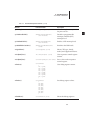
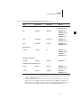
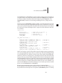
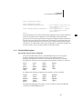
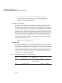
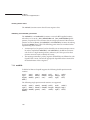
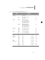
Table 2-1 summarizes supported ARM cache and MMU configurations.
Table 2-1
Supported ARM Cache and MMU Configurations
Core
Cache Type
Memory Management
ARM926e
32 KB instruction cache
32 KB data cache/write buffer
Page-table-based MMU
ARM1136jf-s
Cache size ranges from 4 KB to
36 KB and is detected
automatically during VxWorks
initialization
Page-table-based MMU
For all ARM caches, the cache capabilities must be used with the MMU to resolve
cache coherency problems. When the MMU is enabled, the page descriptor for
each page selects the cache mode, which can be cacheable or non-cacheable. This
page descriptor is configured by filling in the sysPhysMemDesc[ ] structure
defined in the BSP installDir/vxworks-6.2/target/config/bspname/sysLib.c file.
For more information on cache coherency, see the cacheLib reference entry. For
information on MMU support in VxWorks, see the VxWorks Kernel Programmer’s
Guide: Memory Management. For MMU information specific to the ARM family, see
2.4.9 Memory Management Unit (MMU), p.13.
12
2 ARM
2.4 Architecture Considerations
Not all ARM caches support cache locking and unlocking. Therefore, VxWorks for
ARM does not support locking and unlocking of ARM caches. The cacheLock( )
and cacheUnlock( ) routines have no effect on ARM targets and always return
ERROR.
The effects of the cacheClear( ) and cacheInvalidate( ) routines depend on the
CPU type and on which cache is specified.
ARM 926ej-s Cache
The ARM 926e has separate instruction and data caches. Both are enabled by
default. The data cache, if enabled, must be set to copyback mode, as all writes
from the cache are buffered. USER_D_CACHE_MODE must be set to
CACHE_COPYBACK and not changed. The instruction cache is not coherent with
stores to memory. USER_I_CACHE_MODE should be set to
CACHE_WRITETHROUGH and not changed.
On the ARM 926e, it is not possible to invalidate one part of the cache without
invalidating others so, with the data cache specified, the cacheClear( ) routine
pushes dirty data to memory and then invalidates the cache lines. For the
cacheInvalidate( ) routine, unless the ENTIRE_CACHE option is specified, the
entire data cache is invalidated.
ARM 1136jf-s Cache
The ARM 1136jf-s has separate instruction and data caches. Both are enabled by
default. The data cache can be set to copyback or write-through mode on a
per-page basis. The instruction cache is not coherent with stores to memory.
USER_I_CACHE_MODE should be set to CACHE_WRITETHROUGH and not
changed.
2.4.9 Memory Management Unit (MMU)
On ARM CPUs, a specific configuration for each memory page can be set. The
entire physical memory is described by sysPhysMemDesc[ ], which is defined in
installDir/vxworks-6.2/target/config/bspname/sysLib.c. This data structure is made
up of state flags for each page or group of pages. All of the page states defined in
the VxWorks Kernel Programmer’s Guide: Memory Management are available for
virtual memory pages.
All memory management is performed on small pages that are 4 KB in size. The
ARM concepts of sections or large pages are not used.
13
2
VxWorks
Architecture Supplement, 6.2
Cache and Memory Management Interaction
The caching and memory management functions for ARM processors are both
provided on-chip and are very closely interlinked. In general, caching functions on
ARM require the MMU to be enabled. Consequently, if cache support is configured
into VxWorks, MMU support is also included by default. On some CPUs, the
instruction cache can be enabled (in the hardware) without enabling the MMU.
This is not a recommended configuration.
Only certain combinations of MMU and cache-enabling are valid, and there are no
hardware interlocks to enforce this. In particular, enabling the data cache without
enabling the MMU can lead to undefined results. Consequently, if an attempt is
made to enable the data cache by means of the cacheEnable( ) routine before the
MMU has been enabled, the data cache is not enabled immediately. Instead, flags
are set internally so that if the MMU is enabled later, the data cache is enabled with
it. Similarly, if the MMU is disabled, the data cache is also disabled until the MMU
is reenabled.
Support is also included for CPUs that provide a special area in the address space
to be read in order to flush the data cache. ARM BSPs must provide a virtual
address (sysCacheFlushReadArea) for a readable, cached block of address space
that is used for nothing else. If the BSP has an area of the address space that does
not actually contain memory but is readable, it can set the pointer to point to that
area. If it does not, it should allocate some RAM for this area. In either case, the area
must be marked as readable and cacheable in the page tables.
The declaration can be included in the BSP installDir/vxworks-6.2/target
/config/bspname/sysLib.c file. For example:
UINT32 sysCacheFlushReadArea[D_CACHE_SIZE/sizeof(UINT32)];
Alternatively, the declaration can appear in the BSP romInit.s and sysALib.s files.
For example:
.globl
.equ
_sysCacheFlushReadArea
_sysCacheFlushReadArea, 0x50000000
A declaration in installDir/vxworks-6.2/target/config/bspname/sysLib.c of the
following form cannot be used:
UINT32 * sysCacheFlushReadArea = (UINT32 *) 0x50000000;
This form cannot be used because it introduces another level of indirection,
causing the wrong address to be used for the cache flush buffer.
Some systems cannot provide an environment where virtual and physical
addresses are the same. This is particularly important for those areas containing
page tables. To support these systems, the BSP must provide mapping functions to
14
2 ARM
2.4 Architecture Considerations
convert between virtual and physical addresses: these mapping functions are
provided as parameters to the routines cachetypeLibInstall( ) and
mmutypeLibInstall( ). For more information, see BSP Considerations for Cache and
MMU, p.15.
BSP Considerations for Cache and MMU
When building a BSP, the instruction set is selected by choosing the architecture
(that is, by defining CPU to be ARMARCHx); the cache and MMU types are selected
within the BSP by defining appropriate values for the macros ARMMMU and
ARMCACHE and calling the appropriate routines (as shown in Table 2-2) to
support the cache and MMU.
The values definable for MMU include the following:
ARMMMU_NONE
ARMMMU_926E
ARMMMU_1136JF
The values definable for cache include the following:
ARMCACHE_NONE
ARMCACHE_926E
ARMCACHE_1136JF
Defined types are in the header file installDir/vxworks-6.2/target/h/arch/arm/
arm.h. (Support for other caches and MMU types may be added from time to time.)
For example, to define the MMU type for an ARM 926e on the command line,
specify the following option when you invoke the compiler:
-DARMMMU=ARMMMU_926E
To provide the same information in a header or source file, include the following
line in the file:
#define ARMMMU ARMMMU_926E
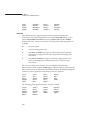
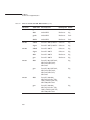
Table 2-2 shows the MMU routines required for each processor type.
Table 2-2
Cache and MMU Routines for Individual Processor Types
Processor
Cache Routine
MMU Routine
ARM 926e
cacheArm926eLibInstall( )
mmuArm926eLibInstall( )
ARM 1136jf
cacheArm1136jfLibInstall( )
mmuArm1136jfLibInstall( )
15
2
VxWorks
Architecture Supplement, 6.2
Each of these routines takes two parameters: function pointers to routines to
translate between virtual and physical addresses and vice-versa. If the default
address map in the BSP is such that virtual and physical addresses are identical
(this is normally the case), the parameters to this routine can be NULL pointers. If
the virtual-to-physical address mapping is such that the virtual and physical
addresses are not the same, but the mapping is as described in the
sysPhysMemDesc[ ] structure, the routines mmuPhysToVirt( ) and
mmuVirtToPhys( ) can be used. If the mapping is different, translation routines
must be provided within the BSP. For further details, see the reference entries for
these routines.
MMU and cache support installation routines must be called as early as possible in
the BSP initialization (before cacheLibInit( ) and vmLibInit( )). This can most
easily be achieved by putting them in a sysHwInit0( ) routine within sysLib.c and
then defining macros in config.h as follows:
#define INCLUDE_SYS_HW_INIT_0
#define SYS_HW_INIT_0() sysHwInit0 ()
During certain cache and MMU operations (for example, cache flushing),
interrupts must be disabled. You may want your BSP to have control over this
procedure. The contents of the variable cacheArchIntMask determine which
interrupts are disabled. This variable has the value I_BIT | F_BIT, indicating that
both IRQs and FIQs are disabled during these operations. If a BSP requires that
FIQs be left enabled, the contents of cacheArchIntMask should be changed to
I_BIT. Use extreme caution when changing the contents of this variable from its
default.
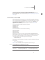
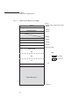
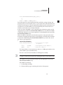
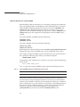
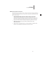
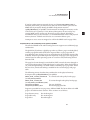
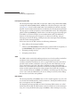
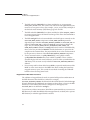
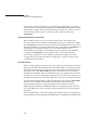
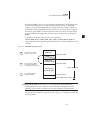
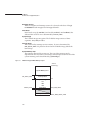
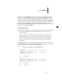
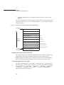
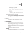
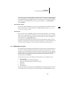
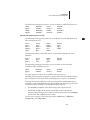
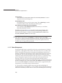
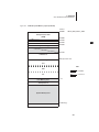
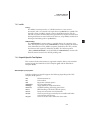
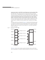
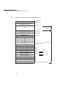
2.4.10 Memory Layout
The VxWorks memory layout (real or virtual, as appropriate) is the same for all
ARM processors. Figure 2-1 shows memory layout, labeled as follows:
Vectors
Table of exception/interrupt vectors.
FIQ Code
Reserved for FIQ handling code.
Shared Memory Anchor
Anchor for the shared memory network and VxMP shared memory objects (if
there is shared memory on the board).
Exception Pointers
Pointers to exception routines, which are used by the vectors.
16
2 ARM
2.5 Migrating Your BSP
Boot Line
ASCII string of boot parameters.
2
Exception Message
ASCII string of fatal exception message.
Initial Stack
Initial stack for usrInit( ), until usrRoot( ) is allocated a stack.
System Image
VxWorks itself (three sections: text, data, and bss). The entry point for
VxWorks is at the start of this region.
WDB Memory Pool
The size of this pool depends on the macro WDB_POOL_SIZE, which defaults
to one-sixteenth of the system memory pool. The target server uses this space
to support host-based tools. Modify WDB_POOL_SIZE under INCLUDE_WDB.
System Memory Pool
Size depends on size of the system image. The sysMemTop( ) routine returns
the end of the free memory pool.
All addresses shown in Figure 2-1 are relative to the start of memory for a
particular target board. The start of memory (corresponding to 0x0 in the memory
layout diagram) is defined as LOCAL_MEM_LOCAL_ADRS under
INCLUDE_MEMORY_CONFIG for each target.
NOTE: The initial stack and system image addresses are configured within the BSP.
2.5 Migrating Your BSP
In order to convert a VxWorks BSP from an earlier VxWorks release to
VxWorks 6.x, you must make certain architecture-independent changes. This
includes making changes to custom BSPs designed to work with a VxWorks 5.5
release and not supported or distributed by Wind River.
This section includes changes and usage caveats specifically related to migrating
ARM BSPs to VxWorks 6.x. For more information on migrating BSPs to this release,
see the VxWorks Migration Guide.
17
VxWorks
Architecture Supplement, 6.2
Figure 2-1
VxWorks System Memory Layout (ARM)
Vectors
Address
+0x0000 LOCAL_MEM_LOCAL_ADRS
+0x0020
Reserved For FIQ Code
Exception Pointers
+0x0100
+0x0120
+0x0600
Shared Memory Anchor
+0x1000
Boot Line
+0x1100
Exception Message
+0x1200
Initial Stack
RAM_LOW_ADRS
System Image
text
KEY
data
= Available
= Reserved
bss
_end
WDB Memory Pool
System Memory Pool
sysMemTop( )
18
2 ARM
2.5 Migrating Your BSP
VxWorks 5.5 Compatibility
The memory layout shown in Figure 2-1 differs from that used for VxWorks 5.5.
The position of the boot line and exception message have been moved to allow
memory page zero protection (kernel hardening).
By default, all BSPs included with this release have the
T2_BOOTROM_COMPATIBILITY option enabled in config.h. This retains
compatibility with VxWorks 5.5 boot ROMs. In this configuration, the symbols are
defined in config.h as follows:
#define SM_ANCHOR_OFFSET
#define BOOT_LINE_OFFSET
#define EXC_MSG_OFFSET
0x600
0x700
0x800
However, kernel hardening is not supported in this configuration. In order to
enable kernel hardening, you must undefine T2_BOOTROM_COMPATIBILITY and
use a VxWorks 6.x boot ROM.
If you create a Workbench project based on a VxWorks 5.5-compatible BSP (that is,
a BSP that has T2_BOOTROM_COMPATIBILITY enabled) and you wish to remove
the compatibility and enable kernel hardening, you must do one of the following:
■
Update your BSP. Then, create a new project based on the modified BSP, and
enable INCLUDE_KERNEL_HARDENING.
or:
■
Undefine T2_BOOTROM_COMPATIBILITY. Enable
INCLUDE_KERNEL_HARDENING and update the values of
SM_ANCHOR_OFFSET, BOOT_LINE_OFFSET, and EXC_MSG_OFFSET to
0x1000, 0x1100, and 0x1200 respectively.
NOTE: VxWorks 5.5-compatible BSPs cannot support kernel hardening.
T2_BOOTROM_COMPATIBILITY and INCLUDE_KERNEL_HARDENING are
mutually exclusive. If both of these components are defined in your config.h file,
Workbench issues a warning when you attempt to build your project.
19
2
VxWorks
Architecture Supplement, 6.2
2.6 Reference Material
Comprehensive information regarding ARM hardware behavior and
programming is beyond the scope of this document. ARM Ltd. provides several
hardware and programming manuals for the ARM processor on its Web site:
http://www.arm.com/documentation/
Wind River recommends that you consult the hardware documentation for your
processor or processor family as necessary during BSP development.
ARM Development Reference Documents
The information given in this section is current at the time of writing; should you
decide to use these documents, you may wish to contact the manufacturer for the
most current version.
■
Advanced RISC Machines, Architectural Reference Manual, Second Edition,
ARM DDI 0100 E, ISBN 0-201-73719-1.
NOTE: This document describes the architecture in general, including
architectural standards for instruction bit fields. More specific information is
found in the data sheets for individual processors, which conform to different
architecture specification versions.
■
ARM System Architecture, by Steve Furber. Addison-Wesley, 1996.
ISBN 0-201-403352-8.
■
ARM Procedure Call Standard (APCS), a version of which is available on the
Internet. Contact ARM for information on the latest version.
20
3
Intel XScale
3.1 Introduction 21
3.2 Supported Processors 22
3.3 Interface Variations 22
3.4 Architecture Considerations 26
3.5 Migrating Your BSP 42
3.6 Reference Material 44
3.1 Introduction
VxWorks for Intel XScale provides the Wind River Workbench development tools
and the VxWorks operating system for the Intel XScale family of processors. The
XScale microarchitecture features an ARM-compatible compact core that operates
at a low power level. The core design supports both big- and little-endian
configurations.
21
VxWorks
Architecture Supplement, 6.2
3.2 Supported Processors
VxWorks for Intel XScale supports XScale architecture CPUs running in ARM
state, in either big- or little-endian mode (for example, IXDP425 and IXDP465
CPUs).
NOTE: VxWorks for Intel XScale provides support for the XScale architecture
rather than for specific CPUs. If your chip is based on the XScale architecture, it
should be supported by this release.
3.3 Interface Variations
This section describes particular features and routines that are specific to XScale
targets in one of the following ways:
■
They are available only on XScale targets.
■
They use parameters specific to XScale targets.
■
They have special restrictions or characteristics on XScale targets.
For more complete documentation on these routines, see the individual reference
entries.
3.3.1 Restrictions on cret( ) and tt( )
The cret( ) and tt( ) routines make assumptions about the standard prolog for
routines. If routines are written in assembly language, or in another language that
generates a different prolog, the cret( ) and tt( ) routines may generate unexpected
results.
The VxWorks kernel is built without a dedicated frame pointer. This is also the
default build option for user application code. As such, cret( ) and tt( ) cannot
provide backtrace information. To enable backtracing for user code using the GNU
compiler, add -fno-omit-frame-pointer to the application’s compiler
command-line options. (Backtracing for user code cannot be enabled using the
Wind River Compiler.)
22
3 Intel XScale
3.3 Interface Variations
tt( ) does not report the parameters to C functions, as it cannot determine these
from the code generated by the compiler.
The tt( ) routine cannot be used for backtracing kernel code.
3
!
CAUTION: The kernel is compiled without backtrace structures. For this reason,
tt( ) does not work within the kernel routines, and cret( ) can sometimes work
incorrectly. Breakpoints and single-stepping should work, even if the code is
compiled without backtrace structures.
3.3.2 cacheLib
The cacheLock( ) and cacheUnlock( ) routines always return ERROR (see
3.4.8 Caches, p.29). Use of the cache and use of the MMU are closely linked on
XScale processors. Consequently, if cacheLib is used, vmLib is also required. In
addition, cacheLib and vmLib calls must be coordinated. For more information,
see 3.4.9 Memory Management Unit (MMU), p.30.
The definition of the symbolic constant _CACHE_ALIGN_SIZE is not related to the
defined CPU type (the latter now defines an architecture). Rather, it is related to the
cache type of the specific CPU being used. Therefore, code (such as device drivers)
in which it is necessary to know the cache line size should use the variable
cacheArchAlignSize instead.
3.3.3 dbgLib
In order to maintain compatibility with hardware-assisted debuggers, VxWorks
for Intel XScale uses only software breakpoints. When you set a software
breakpoint, VxWorks replaces an instruction with a known undefined instruction.
VxWorks restores the original code when the breakpoint is removed; if memory is
examined or disassembled, the original code is shown.
3.3.4 dbgArchLib
If you are using the target shell, the following additional architecture-specific
routines are available:
psrShow( )
Displays the symbolic meaning of a specified processor status register (PSR)
value on the standard output.
23
VxWorks
Architecture Supplement, 6.2
cpsr( )
Returns the contents of the current processor status register (CPSR) of the
specified task.
3.3.5 intALib
intLock( ) and intUnlock( )
The routine intLock( ) returns the I bit from the CPSR as the lock-out key for
the interrupt level prior to the call to intLock( ). The routine intUnlock( ) takes
this value as a parameter. For XScale processors, these routines control the
CPU interrupt mask directly. They do not manipulate the interrupt levels in
the interrupt controller chip.
intIFLock( ) and intIFUnLock( )
The routine intIFLock( ) returns the I and F bits from the CPSR as the lock-out
key in an analogous fashion, and the routine intIFUnlock( ) takes that value as
a parameter. Like intLock( ) and intUnlock( ), these routines control the CPU
interrupt mask directly. The intIFLock( ) is not a replacement for intLock( ); it
should only be used by code (such as FIQ setup code) that requires that both
IRQ and FIQ be disabled.
3.3.6 intArchLib
XScale processors generally have no on-chip interrupt controllers to handle the
interrupts multiplexed on the IRQ pin. Control of interrupts is a BSP-specific
matter. All of these routines are connected by function pointers to routines that
must be provided in the XScale BSPs by a standard interrupt controller driver. For
general information on interrupt controller drivers, see Wind River AppNote46,
Standard Interrupt Controller Devices. (VxWorks application notes are available on
the Wind River Online Support Web site at https://secure.windriver.com
/windsurf/knowledgebase.html.) For special requirements or limitations, see the
appropriate interrupt controller device driver documents.
intLibInit( )
This routine initializes the interrupt architecture library. It is usually called
from sysHwInit2( ) in the BSP code.
STATUS intLibInit(nLevels, nVecs, mode)
The mode argument specifies whether interrupts are handled in preemptive
mode (INT_PREEMPT_MODEL) or non-preemptive mode
(INT_NON_PREEMPT_MODEL).
24
3 Intel XScale
3.3 Interface Variations
intEnable( ) and intDisable( )
The intEnable( ) and intDisable( ) routines affect the masking of interrupts in
the BSP interrupt controller and do not affect the CPU interrupt mask.
3
intVecSet( ) and intVecGet( )
The intVecSet( ) and intVecGet( ) routines are not supported for XScale and
are not present in this release.
intVecShow( )
The intVecShow( ) routine is not supported for XScale and is not present in
this release.
intLockLevelSet( ) and intLockLevelGet( )
The intLockLevelSet( ) and intLockLevelGet( ) routines are not supported for
XScale. The routines are present in this release but are not functional.
intVecBaseSet( ) and intVecBaseGet( )
The intVecBaseSet( ) and intVecBaseGet( ) routines are not supported for
XScale. The routines are present in this release but are not functional.
intUninitVecSet( )
You can use the intUninitVecSet( ) routine to install a default interrupt
handler for all uninitialized interrupt vectors. The routine is called with the
vector number as the only argument.
3.3.7 vmLib
As mentioned for cacheLib, caching and virtual memory are linked on XScale
processors. Use of vmLib requires that cacheLib be included as well, and that calls
to the two libraries be coordinated. For more information, see 3.4.9 Memory
Management Unit (MMU), p.30.
3.3.8 vxALib
mmuReadId( )
The mmuReadId( ) routine is provided to return the processor ID on
processors with MMUs that provide such an ID. This routine should not be
called on CPUs that do not have this type of MMU, doing so causes an
undefined instruction exception.
vxTas( )
The test-and-set primitive vxTas( ) provides a C-callable interface to the ARM
SWPB (swap byte) instruction.
25
VxWorks
Architecture Supplement, 6.2
3.3.9 vxLib
The vxMemProbe( ) routine, which probes an address for a bus error, is supported
by trapping data aborts. If your BSP hardware does not generate data aborts when
illegal addresses are accessed, vxMemProbe( ) does not return the expected
results. The BSP can provide an alternative routine by inserting the address of the
alternate routine in the global variable _func_vxMemProbeHook.
3.4 Architecture Considerations
This section describes characteristics of the XScale processor that you should keep
in mind as you write a VxWorks application. The following topics are addressed:
■
■
■
■
■
■
■
■
■
■
processor mode
byte order
ARM and Thumb state
unaligned accesses
interrupts and exceptions
divide-by-zero handling
floating-point support
caches
memory management unit (MMU)
memory layout
For comprehensive documentation on the XScale architecture and on specific
processors, see the ARM Architecture Reference Manual and the data sheets for the
appropriate processors.
3.4.1 Processor Mode
VxWorks for Intel XScale executes mainly in 32-bit supervisor mode (SVC32).
When exceptions occur that cause the CPU to enter other modes, the kernel
generally switches to SVC32 mode for most of the processing. Tasks running
within a real-time process (RTP) run in user mode.
NOTE: This release does not include support for the 26-bit processor modes, which
are obsolete.
26
3 Intel XScale
3.4 Architecture Considerations
3.4.2 Byte Order
XScale CPUs include support for both little-endian and big-endian byte orders;
libraries for both byte orders are included in this release.
3.4.3 ARM and Thumb State
VxWorks for Intel XScale supports 32-bit instructions (ARM state) only. The 16-bit
instructions set (Thumb state) is not supported.
3.4.4 Unaligned Accesses
Unaligned accesses are not allowed on XScale CPUs and result in a data abort.
3.4.5 Interrupts and Exceptions
When an XScale interrupt or exception occurs, the CPU switches to one of several
exception modes, each of which has a number of dedicated registers. In order to
make the handlers reentrant, the stub routines that VxWorks installs to trap
interrupts and exceptions switch from the exception mode to SVC (supervisor)
mode for further processing. The handler cannot be reentered while executing in
an exception because reentry destroys the link register. When an exception or
base-level interrupt handler is installed by a call to VxWorks, the address of the
handler is stored for use by the stub when the mode switching is complete. The
handler returns to the stub routine to restore the processor state to what it was
before the exception occurred. Exception handlers (excluding interrupt handlers)
can modify the state to be restored by changing the contents of the register set that
is passed to the handler.
XScale processors do not, in general, have on-chip interrupt controllers. All
interrupts except FIQs are multiplexed on the IRQ pin (see Fast Interrupt (FIQ),
p.28). Therefore, routines must be provided within your BSP to enable and disable
specific device interrupts, to install handlers for specific device interrupts, and to
determine the cause of the interrupt and dispatch the correct handler when an
interrupt occurs. These routines are installed by setting function pointers. (For
examples, see the interrupt control modules in installDir/vxworks-6.2/target/
src/drv/intrCtl.) A device driver then installs an interrupt handler by calling
intConnect( ). For more information on interrupt controllers, see Wind River
AppNote46, Standard Interrupt Controller Devices.
27
3
VxWorks
Architecture Supplement, 6.2
Exceptions other than interrupts are handled in a similar fashion: the exception
stub switches to SVC mode and then calls any installed handler. Handlers are
installed by calls to excVecSet( ), and the addresses of installed handlers can be
read through calls to excVecGet( ).
Interrupt Stacks
VxWorks for Intel XScale uses a separate interrupt stack in order to avoid having
to make task interrupt stacks big enough to accommodate the needs of interrupt
handlers. The XScale architecture has a dedicated stack pointer for its IRQ
interrupt mode. However, because the low-level interrupt handling code must be
reentrant, IRQ mode is only used on entry to, and exit from, the handler; an
interrupt destroys the IRQ mode link register. The majority of interrupt handling
code runs in SVC mode on a dedicated SVC-mode interrupt stack.
Fast Interrupt (FIQ)
Fast interrupt (FIQ) is not handled by VxWorks. BSPs can use FIQ as they wish, but
VxWorks code should not be called from FIQ handlers. If this functionality is
required, the preferred mechanism is to downgrade the FIQ to an IRQ by software
access to appropriately-designed hardware which generates an IRQ. The IRQ
handler can then make such VxWorks calls as are normally allowed from interrupt
context.
3.4.6 Divide-by-Zero Handling
There is no native divide-by-zero exception on the XScale architecture. In keeping
with this, neither the GNU compiler nor the Wind River Compiler toolchain
synthesize a software interrupt for this event.
3.4.7 Floating-Point Support
VxWorks for Intel XScale is built using the assumption that there is no hardware
floating-point support present on the target. To perform floating-point arithmetic,
VxWorks instead relies on highly tuned software modules. These modules are
automatically linked into the VxWorks kernel and are available to any application
that requires floating-point support.
28
3 Intel XScale
3.4 Architecture Considerations
The floating-point library used by VxWorks for Intel XScale is licensed from
ARM Ltd. For more information on the floating-point library, see
http://www.arm.com.
3
Return Status
The floating-point math functions supplied with this release do not set errno.
However, return status can be obtained by calling __ieee_status( ).
The __ieee_status( ) prototype is as follows:
unsigned int __ieee_status (unsigned int mask, unsigned int flags);
For example:
d = pow( 0,0 );
status = __ieee_status(FE_IEEE_ALL_EXCEPT, 0);
printf( "pow( 0, 0 )=%g, __ieee_status=%#x\n", d, status );
3.4.8 Caches
XScale processor cores have a variety of cache configurations. This section
discusses these configurations and their relation to the XScale memory
management facilities. The following subsections augment the information in the
VxWorks Kernel Programmer’s Guide: Memory Management.
XScale-based CPUs have separate instruction and data caches, as well as write
buffers. Caches are also available in a variety of sizes and may include minicaches.
An in-depth discussion regarding XScale caches is beyond the scope of this
document. For more detailed information, see the Intel Web site.
In addition to the collection of caches, XScale cores also implement a full
page-table-based memory management unit (MMU). Detailed information
regarding the memory management scheme can also be found on the Intel Web
site.
Table 3-1 summarizes some of the common XScale cache and MMU
configurations.
Table 3-1
Supported XScale Cache and MMU Configurations
Core
Cache Type
Memory Management
XScale
32 KB instruction cache
32 KB data cache/write buffer
2 KB mini data cache
Page-table-based MMU
29
VxWorks
Architecture Supplement, 6.2
For all XScale caches, the cache capabilities must be used with the MMU to resolve
cache coherency problems. When the MMU is enabled, the page descriptor for
each page selects the cache mode, which can be cacheable or non-cacheable. This
page descriptor is configured by filling in the sysPhysMemDesc[ ] structure
defined in the BSP installDir/vxworks-6.2/target/config/bspname/sysLib.c file.
For more information on cache coherency, see the cacheLib reference entry. For
information on MMU support in VxWorks, see the VxWorks Kernel Programmer’s
Guide: Memory Management. For MMU information specific to the XScale family,
see 3.4.9 Memory Management Unit (MMU), p.30.
Not all XScale caches support cache locking and unlocking. Therefore, VxWorks
for Intel XScale does not support locking and unlocking of XScale caches. The
cacheLock( ) and cacheUnlock( ) routines have no effect on XScale targets and
always return ERROR.
The effects of the cacheClear( ) and cacheInvalidate( ) routines depend on the
CPU type and on which cache is specified.
All XScale processors contain an instruction cache and a data cache. By default,
VxWorks uses both caches; that is, both are enabled. To disable the instruction
cache, highlight the USER_I_CACHE_ENABLE macro in the Params tab under
INCLUDE_CACHE_ENABLE and remove the value TRUE; to disable the data cache,
highlight the USER_D_CACHE_ENABLE macro and remove TRUE.
It is not appropriate to think of the mode of the instruction cache. The instruction
cache is a read cache that is not coherent with stores to memory. Therefore, code
that writes to cacheable instruction locations must ensure instruction cache
validity. Set the USER_I_CACHE_MODE parameter in the Params tab under
INCLUDE_CACHE_MODE to CACHE_WRITETHROUGH, and do not change it.
With the data cache specified, the cacheClear( ) routine first pushes dirty data to
memory and then invalidates the cache lines, while the cacheInvalidate( ) routine
simply invalidates the lines (in which case, any dirty data contained in the lines is
lost). With the instruction cache specified, both routines have the same result: they
invalidate all of the instruction cache. Because the instruction cache is separate
from the data cache, there can be no dirty entries in the instruction cache, so no
dirty data can be lost.
3.4.9 Memory Management Unit (MMU)
On XScale CPUs, a specific configuration for each memory page can be set. The
entire physical memory is described by sysPhysMemDesc[ ], which is defined in
installDir/vxworks-6.2/target/config/bspname/sysLib.c. This data structure is made
30
3 Intel XScale
3.4 Architecture Considerations
up of state flags for each page or group of pages. All of the page states defined in
the VxWorks Kernel Programmer’s Guide: Memory Management are available for
virtual memory pages. In addition, XScale-based processors support the
MMU_STATE_CACHEABLE_MINICACHE (or
VM_STATE_CACHEABLE_MINICACHE) flag, allowing page-level control of the
CPU minicache.
All memory management is performed on small pages that are 4 KB in size. The
ARM concepts of sections or large pages are not used.
XScale Memory Management Extensions and VxWorks
The Intel XScale processor core introduces extensions to ARM Architecture
Version 5. Among these extensions are the addition of the X bit and the P bit. This
section describes VxWorks support for these extensions.
NOTE: This section supplements the documentation provided with the
vmBaseLib and vmLib reference entries and in the VxWorks Kernel Programmer’s
Guide: Memory Management.
The Intel XScale processor extends the page attributes defined by the C and B bits
in the page descriptors with an additional X bit. This bit allows four more
attributes to be encoded when X=1. These new encodings include allocating data
for the mini-data cache and the write-allocate cache.
If you are using the MMU, the cache modes are controlled by the cache mode
values set in the sysPhysMemDesc[ ] table defined in installDir/vxworks-6.2
/target/config/bspname/sysLib.c within the BSP directory.
The XScale processor retains the ARM definitions of the C and B encoding when
X= 0, which differs from the behavior on the first generation Intel StrongARM
processors. The memory attribute for the mini-data cache has been relocated and
replaced with the write-through caching attribute.
When write-allocate is enabled, a store operation that misses the data cache
(cacheable data only) generates a line fill. If disabled, a line fill only occurs when a
load operation misses the data cache (cacheable data only).
Write-through caching causes all store operations to be written to memory,
whether they are cacheable or not cacheable. This feature is useful for maintaining
data cache coherency.
31
3
VxWorks
Architecture Supplement, 6.2
The type extension (TEX) field is present in several of the descriptor types. In the
XScale processor, only the least significant bit (LSB) of this field is used; this is
called the X bit.
A small page descriptor does not have a TEX field. For this type of descriptor, TEX
is implicitly zero; that is, this descriptor operates as if the X bit has a zero value.
The X bit, when set, modifies the meaning of the C and B bits.
When examining these bits in a descriptor, the instruction cache only utilizes the C
bit. If the C bit is clear, the instruction cache considers a code fetch from that
memory to be non-cacheable, and does not fill a cache entry. If the C bit is set,
fetches from the associated memory region are cached.
If the X bit for a descriptor is zero, the C and B bits operate as mandated by the
ARM architecture. If the X bit for a descriptor is one, the C and B bits meaning is
extended.
If the MMU is disabled, all data accesses are non-cacheable and non-bufferable.
This is the same behavior as when the MMU is enabled, and a data access uses a
descriptor with X, C, and B all set to zero.
The X, C, and B bits determine when the processor should place new data into the
data cache. The cache places data into the cache in lines (also called blocks). Thus,
the basis for making a decision about placing new data into the cache is called a
line allocation policy.
If the line allocation policy is read-allocate, all load operations that miss the cache
request a 32-byte cache line from external memory and allocate it into either the
data cache or mini-data cache (this assumes the cache is enabled). Store operations
that miss the cache do not cause a line to be allocated.
If a read/write-allocate is in effect, and if cache is enabled, load or store operations
that miss the cache request a 32-byte cache line from external memory.
The other policy determined by the X, C, and B bits is the write policy. A
write-through policy instructs the data cache to keep external memory coherent by
performing stores to both external memory and the cache. A write-back policy
only updates external memory when a line in the cache is cleaned or needs to be
replaced with a new line. Generally, write-back provides higher performance
because it generates less data traffic to external memory.
The write buffer is always enabled which means stores to external memory are
buffered. The K bit in the auxiliary control register (CP15, register 1) is a global
enable/disable for allowing coalescing in the write buffer. When this bit disables
coalescing, no coalescing occurs regardless of the value of the page attributes. If
32
3 Intel XScale
3.4 Architecture Considerations
this bit enables coalescing, the page attributes X, C, and B are examined to see if
coalescing is enabled for each region of memory.
All reads and writes to external memory occur in program order when coalescing
is disabled in the write buffer. If coalescing is enabled in the write buffer, writes
may occur out of program order to external memory. In this case, program
correctness is maintained by comparing all store requests with all valid entries in
the fill buffer.
The write buffer and fill buffer support a drain operation such that before the next
instruction executes, all XScale processor data requests to external memory—
including the write operations in the bus controller—are complete.
Writes to a region marked non-cacheable and non-bufferable (page attributes C, B,
and X set to zero) cause execution to stall until the write completes.
If software is running in a privileged mode, it can explicitly drain all buffered
writes.
Non-cache memory (X=0, C=0, and B=0) should only be used if required (as is
often the case for I/O devices). Accessing non-cacheable memory is likely to cause
the processor to stall frequently due to the long latency of memory reads.
VxWorks includes support for the X bit and there are now three new states
supported in vmLib.h that allow you to set up buffers to use these extended states.
The following state flags have been added to vmLib.h:
MMU_STATE_CACHEABLE_MINICACHE cache policy is determined by the MD
(VM_STATE_CACHEABLE_MINICACHE) field of the auxiliary control register
VM_STATE_EX_CACHEABLE
write-back, read/write allocate
VM_STATE_EX_CACHEABLE_NOT
VM_STATE_MASK_EX_CACHEABLE
VM_STATE_EX_BUFFERABLE
writes do not coalesce into buffers
VM_STATE_EX_BUFFERABLE_NOT
VM_STATE_MASK_EX_BUFFERABLE
If MMU_STATE_CACHEABLE_MINICACHE (or
VM_STATE_CACHEABLE_MINICACHE) is set, pages set to this state using
vmStateSet( ) result in those pages being cached in the minicache, and not in the
main data cache.
33
3
VxWorks
Architecture Supplement, 6.2
Calling cacheInvalidate(DATA_CACHE, ENTIRE_CACHE) also invalidates the
minicache, but in all other aspects, no support is provided for the minicache, and
you are entirely responsible for ensuring cache coherency.
If INCLUDE_MMU_BASIC and INCLUDE_SHOW_ROUTINES are defined, you may
use vmContextShow( ) to display a virtual memory context on the standard
output device. Extended bit states for vmContextShow( ) are defined as:
XC-
VM_STATE_EX_CACHEABLE_NOT
XC+
VM_STATE_EX_CACHEABLE
XB-
VM_STATE_EX_BUFFERABLE_NOT
XB+
VM_STATE_EX_BUFFERABLE
For more information on the extended page table and X bit support, see the Intel
XScale Core Developer's Manual (available from Intel).
Setting the XScale P Bit in VxWorks
The XScale architecture introduces the P bit in the MMU first level page
descriptors, allowing an application specific standard product (ASSP) to identify a
new memory attribute. The bi-endian version of the IXP42x processor implements
the P bit to control address and data byte swapping and requires support for the P
bit in the first level descriptor and in the auxiliary control register (CP15, Rn 1,
O2 1). The setting of the P bit in a first level descriptor enables address or data byte
swapping on a per-section (1 MB) basis. As page table walks are performed with
the MMU disabled, bit 1 in the auxiliary control register enables byte swapping for
the page table walks.
Because VxWorks MMU support operates on a 4 KB page basis rather than on
1 MB regions, support for the P bit on a per region basis is best accomplished with
a new interface that avoids excessive overhead during MMU initialization. An
additional interface to the auxiliary control register is required as well.
The architecture-specific support code for the XScale MMU has been modified to
support the P bit. A byte array of the size NUM_L1_DESCS (the number of first level
descriptors) has been added. Each byte within the array represents the state of the
P bit for the corresponding region; zero if the P bit is not to be set and one if it is.
The default value is zero. For example:
#if (ARMMMU == ARMMMU_XSCALE)
/*
* The array used to keep XSCALE mmu 'P' bit state for init purposes.
*/
34
3 Intel XScale
3.4 Architecture Considerations
LOCAL UCHAR mmuArmXSCALEPBit[NUM_L1_DESCS] =
{
0,
};
#endif /* ARMMMU == ARMMMU_XSCALE */
3
Four subroutines have been implemented that enable the setting, clearing, and
querying of the state of the P bit status on a per-region basis and within the CP15
auxiliary control register. All of the implemented region-specific subroutines have
two behaviors, one if the MMU is not yet initialized by the current instance of
VxWorks, and another if it is already initialized.
In the case where the MMU is not yet initialized, the subroutines operate on the
appropriate bytes within the mmuArmXSCALEPBit array only. When the MMU
is initialized, the P bit is set on a per-region basis as determined by the state of the
mmuArmXSCALEPBit array.
When the MMU is initialized, the subroutines operate on the current first level
descriptor, providing interrupt lockout, cache flushing, and TLB cache invalidates
as necessary. Additionally, the mmuArmXSCALEPBit array mirrors the state of
the P bit on a per-region basis.
■
mmuArmXSCALEPBitSet( )
STATUS mmuArmXSCALEPBitSet
(
void *
UINT32
)
virtAddr,
size
/* Set the P bit in a region
or regions */
/* The beginning virtual address */
/* The size in bytes */
The virtual address is converted into an index to a 1 MB region within 32 -bit
virtual address space (rounded down).
The size is converted to the number of 1 MB regions to modify.
NOTE: A virtual address near the end of a 1 MB region and a size of less than
or equal to 1 MB sets the P bit for the 1 MB region of the virtual address only.
If the MMU is not yet initialized, modify only the appropriate areas in the
mmuArmXSCALEPBit array.
If the MMU is initialized:
a.
Lockout IRQs and FIQs.
b.
Write-enable the pages containing the first level descriptors.
35
VxWorks
Architecture Supplement, 6.2
c.
Modify the selected first level descriptors, mirroring each region's state in
the mmuArmXSCALEPBit array, and flush the data cache for each
region’s first level descriptor.
d. When all selected regions have been processed, flush and invalidate the
TLB caches.
e.
Write-protect the pages containing the first level descriptors.
f.
Re-enable IRQs and FIQs.
ERROR is returned if virtAddr + size overflows the 32-bit virtual address
space. Otherwise, OK is returned.
■
mmuPArmXSCALEBitClear( )
STATUS mmuPArmXSCALEBitClear
(
void *
virtAddr,
UINT32
size
)
/* Clear the P bit in a region(s) */
/* The beginning virtual address */
/* The size in bytes */
The virtual address is converted into an index to a 1 MB region within 32-bit
virtual address space (rounded down).
The size is converted to the number of 1 MB regions to modify.
NOTE: A virtual address near the end of a 1 MB region and a size of less than
or equal to 1 MB clears the P bit for the 1 MB region of the virtual address only.
If the MMU is not yet initialized, modify only the appropriate bytes in the
mmuArmXSCALEPBit array.
If the MMU is initialized
a.
Lockout IRQs and FIQs.
b.
Write-enable the pages containing the first level descriptors.
c.
Modify the selected first level descriptors, mirroring each region's state in
the mmuArmXSCALEPBit array, and flush the data cache for each regions
first level descriptor.
d. When all selected regions have been processed, flush and invalidate the
TLB caches.
36
e.
Write-protect the pages containing the first level descriptors
f.
Re-enable IRQs and FIQs.
3 Intel XScale
3.4 Architecture Considerations
ERROR is returned if virtAddr + size overflows 32-bit virtual address space.
Otherwise, OK is returned.
■
mmuArmXSCALEPBitGet( )
STATUS mmuArmXSCALEPBitGet
(
void *
virtAddr
)
3
/* The beginning virtual address */
The virtual address is converted into an index to a 1 MB region within 32-bit
virtual address space (rounded down).
If the MMU is not yet initialized, return the value of the selected byte in the
mmuArmXSCALEPBit array.
If the MMU is initialized:
a.
Return the state of the P bit in the selected first level descriptor.
STATUS mmuArmXSCALEAcrGet
(
void
)
b.
Return the contents of the CP15 Auxiliary Control Register, (CP15, 0, r0, c1,
c0, 1).
void mmuArmXSCALEAcrSet
(
UINT32
acr
/@ value to load into ACR @/
)
c.
Write the CP15 auxiliary control register with the contents of ACR.
Setting the P Bit in Virtual Memory Regions
There are two available methods to set the P bit in a region, or regions, of virtual
memory. The first, and preferred method, is to modify the sysHwInit0( ) routine
within installDir/vxworks-6.2/target/config/bspname/sysLib.c to call
mmuPBitSet( ) prior to the initialization of the MMU.
The second is to modify the state through calls to mmuPBitSet( ) and
mmuPBitClear( ) during run-time. This method is less desirable due to the impact
that disabling IRQs and FIQs may have on the application.
An example of the preferred method follows (from installDir/vxworks-6.2
/target/config/bspname/sysLib.c).
#ifdef INCLUDE_MMU
/* Install the appropriate MMU library and translation routines */
mmuArmXSCALELibInstall (mmuPhysToVirt, mmuVirtToPhys);
#ifdef IXP425_ENABLE_P_BITS
37
VxWorks
Architecture Supplement, 6.2
{
int acrValue;
/* Set all DRAM regions with P bit */
mmuArmXSCALEPBitSet((void *)IXP425_SDRAM_BASE, LOCAL_MEM_SIZE);
#ifdef
INCLUDE_PCI
/* Set PCI regions with P bit */
mmuArmXSCALEPBitSet((void *)IXP425_PCI_BASE, IXP425_PCI_SP_SIZE);
#endif
/* Make table walks use P bit */
acrValue = mmuArmXSCALEAcrGet();
acrValue |= 0x2; /* Set the P bit in the ACR */
mmuArmXSCALEAcrSet( acrValue );
}
#endif /* IXP425_ENABLE_P_BITS */
#endif /* INCLUDE_MMU */
Cache and Memory Management Interaction
The caching and memory management functions on XScale processors are both
provided on-chip and are very closely interlinked. In general, caching functions on
XScale require the MMU to be enabled. Consequently, if cache support is
configured into VxWorks, MMU support is also included by default. On some
CPUs, the instruction cache can be enabled (in the hardware) without enabling the
MMU; however, this is not a recommended configuration.
Only certain combinations of MMU and cache enabling are valid, and there are no
hardware interlocks to enforce this. In particular, enabling the data cache without
enabling the MMU can lead to undefined results. Consequently, if an attempt is
made to enable the data cache by means of the cacheEnable( ) routine before the
MMU has been enabled, the data cache is not enabled immediately. Instead, flags
are set internally so that if the MMU is enabled later, the data cache is enabled with
it. Similarly, if the MMU is disabled, the data cache is also disabled, until the MMU
is reenabled.
Support is provided for BSPs that include separate static RAM for the MMU
translation tables. This support requires the ability to specify an alternate source of
memory other than the system memory partition. The BSP should set a global
function pointer, _func_armPageSource, to point to a routine that returns a
memory partition identifier describing memory to be used as the source for
translation table memory. If this function pointer is NULL, the system memory
partition is used. The BSP must modify the function pointer before calling
38
3 Intel XScale
3.4 Architecture Considerations
mmuLibInit( ). The initial memory partition must be large enough for all
requirements; it does not expand dynamically or overflow into the system memory
partition if it fills.
Support is also included for CPUs that provide a special area in the address space
to be read in order to flush the data cache. XScale BSPs must provide a virtual
address (sysCacheFlushReadArea) of a readable, cached block of address space
that is used for nothing else. If the BSP has an area of the address space that does
not actually contain memory but is readable, it can set the pointer to point to that
area. If it does not, it should allocate some RAM for this area. In either case, the area
must be marked as readable and cacheable in the page tables.
The declaration can be included in the BSP installDir/vxworks-6.2/target
/config/bspname/sysLib.c file. For example:
UINT32 sysCacheFlushReadArea[D_CACHE_SIZE/sizeof(UINT32)];
Alternatively, the declaration can appear in the BSP romInit.s and sysALib.s files.
For example:
.globl
.equ
_sysCacheFlushReadArea
_sysCacheFlushReadArea, 0x50000000
A declaration in installDir/vxworks-6.2/target/config/bspname/sysLib.c of the
following form cannot be used:
UINT32 * sysCacheFlushReadArea = (UINT32 *) 0x50000000;
This form cannot be used because it introduces another level of indirection,
causing the wrong address to be used for the cache flush buffer.
Some systems cannot provide an environment where virtual and physical
addresses are the same. This is particularly important for those areas containing
page tables. To support these systems, the BSP must provide mapping functions to
convert between virtual and physical addresses: these mapping functions are
provided as parameters to the routines cachetypeLibInstall( ) and
mmutypeLibInstall( ). For more information, see BSP Considerations for Cache and
MMU, p.40.
All XScale BSPs using CPUs with a minicache must provide a similar virtual
address (sysMinicacheFlushReadArea) of an area used to flush the minicache. It
must be marked as cacheable within the minicache (that is, it must have the
MMU_STATE_CACHEABLE_MINICACHE (or
VM_STATE_CACHEABLE_MINICACHE state).
39
3
VxWorks
Architecture Supplement, 6.2
BSP Considerations for Cache and MMU
When building a BSP, the instruction set is selected by choosing the architecture
(that is, by defining CPU to be XSCALE); the cache and MMU types are selected
within the BSP by defining appropriate values for the macros ARMMMU and
ARMCACHE and calling the appropriate routines (as shown in Table 3-2) to
support the cache and MMU. Setting the preprocessor variables ARMMMU and
ARMCACHE ensures that support for the appropriate cache and MMU type is
enabled.
The values definable for MMU include the following:
ARMMMU_NONE
ARMMMU_XSCALE
The values definable for cache include the following:
ARMCACHE_NONE
ARMCACHE_XSCALE
Defined types are in the header file installDir/vxworks-6.2/target/h/arch/arm/arm.h.
(Support for other caches and MMU types may be added from time to time.)
For example, to define the MMU type for an XScale processor on the command
line, specify the following option when you invoke the compiler:
-DARMMMU=ARMMMU_XSCALE
To provide the same information in a header or source file, include the following
line in the file:
#define ARMMMU ARMMMU_XSCALE
Table 3-2 shows the cache and MMU routines required for XScale processors.
Table 3-2
Cache and MMU Routines for Individual Processor Types
Processor
Cache Routine
MMU Routine
XScale
cacheArmXScaleLibInstall( )
mmuArmXScaleLibInstall( )
Each of these routines take two parameters: function pointers to routines to
translate between virtual and physical addresses and vice-versa. If the default
address map in the BSP is such that virtual and physical addresses are identical
(this is normally the case), the parameters to the routine can be NULL pointers. If
the virtual-to-physical address mapping is such that the virtual and physical
addresses are not the same, but the mapping is as described in the
sysPhysMemDesc[ ] structure, the routines mmuPhysToVirt( ) and
40
3 Intel XScale
3.4 Architecture Considerations
mmuVirtToPhys( ) can be used. If the mapping is different, translation routines
must be provided within the BSP. For further details, see the reference entries for
the routines.
MMU and cache support installation routines must be called as early as possible in
the BSP initialization (before cacheLibInit( ) and vmLibInit( )). This can most
easily be achieved by putting them in a sysHwInit0( ) routine within sysLib.c and
then defining the macros in config.h as follows:
#define INCLUDE_SYS_HW_INIT_0
#define SYS_HW_INIT_0() sysHwInit0 ()
During certain cache and MMU operations (for example, cache flushing),
interrupts must be disabled. You may want your BSP to have control over this
procedure. The contents of the variable cacheArchIntMask determine which
interrupts are disabled. This variable has the value I_BIT | F_BIT, indicating that
both IRQs and FIQs are disabled during these operations. If a BSP requires that
FIQs be left enabled, the contents of cacheArchIntMask should be changed to
I_BIT. Use extreme caution when changing the contents of this variable from its
default.
3.4.10 Memory Layout
The VxWorks memory layout (real or virtual, as appropriate) is the same for all
XScale processors. Figure 3-1 shows memory layout, labeled as follows:
Vectors
Table of exception/interrupt vectors.
FIQ Code
Reserved for FIQ handling code.
Shared Memory Anchor
Anchor for the shared memory network and VxMP shared memory objects (if
there is shared memory on the board).
Exception Pointers
Pointers to exception routines, which are used by the vectors.
Boot Line
ASCII string of boot parameters.
Exception Message
ASCII string of fatal exception message.
41
3
VxWorks
Architecture Supplement, 6.2
Initial Stack
Initial stack for usrInit( ), until usrRoot( ) is allocated a stack.
System Image
VxWorks itself (three sections: text, data, and bss). The entry point for
VxWorks is at the start of this region.
WDB Memory Pool
The size of this pool depends on the macro WDB_POOL_SIZE, which defaults
to one-sixteenth of the system memory pool. The target server uses this space
to support host-based tools. Modify WDB_POOL_SIZE under INCLUDE_WDB.
System Memory Pool
Size depends on size of the system image. The sysMemTop( ) routine returns
the end of the free memory pool.
All addresses shown in Figure 3-1 are relative to the start of memory for a
particular target board. The start of memory (corresponding to 0x0 in the memory
layout diagram) is defined as LOCAL_MEM_LOCAL_ADRS under
INCLUDE_MEMORY_CONFIG for each target.
NOTE: The initial stack and system image addresses are configured within the BSP.
3.5 Migrating Your BSP
In order to convert a VxWorks BSP from an earlier VxWorks release to
VxWorks 6.2, you must make certain architecture-independent changes. This
includes making changes to custom BSPs designed to work with a VxWorks 5.5
release and not supported or distributed by Wind River.
This section includes changes and usage caveats specifically related to migrating
Intel XScale BSPs to VxWorks 6.2. For more information on migrating BSPs to
VxWorks 6.2, see the VxWorks Migration Guide.
VxWorks 5.5 Compatibility
The memory layout shown in Figure 3-1 differs from that used for VxWorks 5.5.
The position of the boot line and exception message have been moved to allow
memory page zero protection (kernel hardening).
42
3 Intel XScale
3.5 Migrating Your BSP
Figure 3-1
VxWorks System Memory Layout (XScale)
Vectors
Address
+0x0000 LOCAL_MEM_LOCAL_ADRS
+0x0020
Reserved for FIQ code
Exception Pointers
+0x0100
+0x0120
+0x1000
Boot Line
+0x1100
Exception Message
+0x1200
Initial Stack
RAM_LOW_ADRS
System Image
text
KEY
data
= Available
= Reserved
bss
_end
WDB Memory Pool
System Memory Pool
sysMemTop( )
43
3
VxWorks
Architecture Supplement, 6.2
By default, all BSPs included with this release have the
T2_BOOTROM_COMPATIBILITY option enabled in config.h. This retains
compatibility with VxWorks 5.5 boot ROMs. In this configuration, the symbols are
defined in config.h as follows:
#define SM_ANCHOR_OFFSET
#define BOOT_LINE_OFFSET
#define EXC_MSG_OFFSET
0x600
0x700
0x800
However, kernel hardening is not supported in this configuration. In order to
enable kernel hardening, you must undefine T2_BOOTROM_COMPATIBILITY and
use a VxWorks 6.x boot ROM.
If you create a Workbench project based on a VxWorks 5.5-compatible BSP (that is,
a BSP that has T2_BOOTROM_COMPATIBILITY enabled) and you wish to remove
the compatibility and enable kernel hardening, you must do one of the following:
■
Update your BSP. Then, create a new project based on the modified BSP and
enable INCLUDE_KERNEL_HARDENING.
or:
■
Undefine T2_BOOTROM_COMPATIBILITY. Enable
INCLUDE_KERNEL_HARDENING and update the values of
SM_ANCHOR_OFFSET, BOOT_LINE_OFFSET, and EXC_MSG_OFFSET to
0x1000, 0x1100, and 0x1200 respectively.
NOTE: VxWorks 5.5-compatible BSPs cannot support kernel hardening.
T2_BOOTROM_COMPATIBILITY and INCLUDE_KERNEL_HARDENING are
mutually exclusive. If both of these components are defined in your config.h file,
Workbench issues a warning when you attempt to build your project.
3.6 Reference Material
Comprehensive information regarding Intel XScale hardware behavior and
programming is beyond the scope of this document. Intel provides several
hardware and programming manuals for the Intel XScale processor on its Web site:
http://www.intel.com/design/intelxscale
Wind River recommends that you consult the hardware documentation for your
processor or processor family as necessary during BSP development.
44
3 Intel XScale
3.6 Reference Material
ARM Development Reference Documents
The information given in this section is current at the time of writing; should you
decide to use these documents, you may wish to contact the manufacturer for the
most current version.
■
Advanced RISC Machines, Architectural Reference Manual, Second Edition,
ARM DDI 0100 E, ISBN 0-201-73719-1. This document describes the
architecture in general, including architectural standards for instruction bit
fields. More specific information is found in the data sheets for individual
processors, which conform to different architecture specification versions.
■
ARM System Architecture, by Steve Furber. Addison-Wesley, 1996.
ISBN 0-201-403352-8.
■
ARM Procedure Call Standard (APCS), a version of which is available on the
Internet. Contact ARM for information on the latest version.
45
3
VxWorks
Architecture Supplement, 6.2
46
4
Intel Architecture
4.1 Introduction 47
4.2 Supported Processors 47
4.3 Interface Variations 49
4.4 Architecture Considerations 60
4.5 Reference Material 84
4.1 Introduction
This chapter provides information specific to VxWorks development on Intel
Architecture P5 (Pentium), P6 (PentiumPro, II, III), P7 (Pentium 4), and Pentium M
family processor targets including their Celeron and Xeon series variants.
4.2 Supported Processors
This release supports Intel P5, P6, P7, and Pentium M family processors. This
section provides information on the characteristics of each of these families,
47
VxWorks
Architecture Supplement, 6.2
including their major differences. For more information, refer to your target
hardware documentation.
The P5 (Pentium) architecture is a third-generation 32-bit CPU. It has a 64-bit data
bus and a 32-bit address bus, separate 8 KB L1 instruction and data caches,
superscalar dispatch/execution units, branch prediction, two execution pipelines,
and a write-back data cache protocol. Some P5 family processors also include
support for MMX technology. This technology uses the single-instruction,
multiple-data (SIMD) execution model to perform parallel computations on
packed integer data contained in the 64-bit MMX registers.
P6 micro-architecture family processors include PentiumPro, Pentium II, Pentium
III, Pentium M, and their variant Xeon/Celeron processors. P6 is a three-way
superscalar architecture that executes up to three instructions per clock cycle. It has
micro-data flow analysis, out-of-order execution, superior branch prediction, and
speculative execution. Three instruction decode units work in parallel to decode
object code into smaller operations called micro-ops. These micro-ops can be
executed out-of-order by the five parallel execution units. The retirement unit
retires completed micro-ops in their original program order, taking into account
any branches. The P6 architecture has separate 8 KB L1 instruction and data caches
and a 256 KB L2 unified cache. The data cache uses the MESI protocol to support a
more efficient write-back mode. The cache consistency is maintained with the
MESI protocol and the bus snooping mechanism. Pentium II adds MMX
technology, new packaging, 16 KB L1 instruction and data caches, and a 256 KB
(512 KB or 1 MB) L2 unified cache. Pentium III introduces the Streaming SIMD
Extensions (SSE) that extend the SIMD model with a new set of 128-bit registers
and the ability to perform SIMD operations on packed single-precision
floating-point values. Pentium M processors utilize a new micro-architecture in
order to provide high performance and low power consumption. These processors
include cache and processor bus power management and large L1 and L2 caches.
The P7 (Pentium 4) processor is based on the NetBurst micro-architecture that
allows processors to operate at significantly higher clock speeds and performance
levels. It has a rapid execution engine, hyper pipelined technology, advanced
dynamic execution, a new cache subsystem, Streaming SIMD Extensions 2 (SSE2),
and a 400 MHz system bus.
The x86 architecture supports three operating modes: protected mode,
real-address mode, and virtual-8086 mode. Protected mode is the native operating
mode of the 32-bit processor. All instructions and architectural features are
available in this mode for the highest performance and capability. Real-address
mode provides the programming environment of the Intel 8086 processor.
Virtual-8086 mode lets the processor execute 8086 software in a protected mode,
48
4 Intel Architecture
4.3 Interface Variations
multitasking environment. VxWorks uses 32-bit protected mode. For more
information, see the VxWorks Kernel Programmer’s Guide.
4
4.3 Interface Variations
This section describes particular features and routines that are specific to Intel
Architecture targets in any of the following ways:
■
available only for Intel Architecture targets
■
parameters specific to Intel Architecture targets
■
special restrictions or characteristics on Intel Architecture targets
For complete documentation, see the reference entries for the libraries, routines,
and tools discussed in the following sections.
4.3.1 Supported Routines in mathALib
For Intel Architecture targets, the following double-precision floating-point
routines are supported:
acos( )
cosh( )
irint( )
round( )
tanh( )
asin( )
exp( )
iround( )
sin( )
trunc( )
atan( )
fabs( )
log( )
sincos( )
atan2( )
floor( )
log10( )
sinh( )
ceil( )
fmod( )
log2( )
sqrt( )
cos( )
infinity( )
pow( )
tan( )
The corresponding single-precision floating-point routines are not supported. In
this release, hyperbolic cosine, sine, and tangent routines are supported. For more
information, see the reference entry for mathALib and the individual reference
entries for each routine.
4.3.2 Architecture-Specific Global Variables
The files sysLib.c and sysALib.s contain the global variables shown in Table 4-1.
49
VxWorks
Architecture Supplement, 6.2
Table 4-1
Architecture-Specific Global Variables
Global Variable
Value
Description
sysCsSuper
0x08
Code selector for the supervisor mode
task.
sysCsExc
0x18
Code selector for exceptions.
sysCsInt
0x20
Code selector for interrupts.
sysIntIdtType
0x0000fe00
(default)
= trap gate
This variable is used when VxWorks
initializes the interrupt vector table.
The choice of trap gate versus
interrupt gate affects all interrupts
(vectors 0x20 through 0xff).
0x0000ee00
= interrupt gate
sysGdt[ ]
0xffff limit (default)
sysProcessor
The processor type (set by the
0 = i386
VxWorks sysCpuProbe( ) routine).
1 = i486
2 = P5/Pentium
4 = P6/PentiumPro, II,
III, Pentium M
5 = P7/Pentium 4
sysCoprocessor 0 = no coprocessor
1 = 387 coprocessor
2 = 487 coprocessor
sysCpuId
50
CPUID structure
The global descriptor table begins
with five entries. The first is a null
descriptor. The second and third are
for task-level routines. The fourth is
for exceptions. The fifth is for
interrupt-level routines. If kernel
hardening is enabled, additional
entries are added for task gate
management of the OSM stack.
The type of floating-point coprocessor
(set by the VxWorks fppProbe( )
routine).
Dynamically obtained processor
identification and supported features
(set by VxWorks sysCpuProbe( )).
4 Intel Architecture
4.3 Interface Variations
4.3.3 Architecture-Specific Routines
Table 4-2 provides information for a number of architecture-specific routines.
Other architecture-specific routines are described throughout this section.
Table 4-2
4
Architecture-Specific Routines
Routine
Function Header
Description
fppArchSwitchHookEnable( ) STATUS fppArchSwitchHookEnable Enables or disables the
(BOOL enable)
architecture-specific FPU
switch hook routine that
detects illegal FPU/MMX
usage.
fppCtxShow( )
void fppCtxShow
(FP_CONTEXT * f)
Prints the contents of a task’s
floating-point register.
fppRegListShow( )
void fppRegListShow (void)
Prints a list of available
registers.
intStackEnable( )
STATUS intStackEnable
(BOOL enable)
Enables or disables the
interrupt stack usage. TRUE to
enable, FALSE to disable
pentiumBts( )
STATUS pentiumBts
(char * pFlag)
Executes an atomic
compare-and-exchange
instruction to set a bit. (P5, P6,
and P7)
pentiumBtc( )
STATUS pentiumBtc
(char * pFlag)
Executes an atomic
compare-and-exchange
instruction to clear a bit. (P5, P6,
and P7)
pentiumMcaEnable( )
void pentiumMcaEnable
(BOOL enable)
Enables or disables the MCA
(machine check architecture).
(P5, P6, and P7)
pentiumMcaShow( )
void pentiumMcaShow (void)
Shows machine check global
control registers and error
reporting register banks. (P5,
P6, and P7)
51
VxWorks
Architecture Supplement, 6.2
Table 4-2
Architecture-Specific Routines (cont’d)
Routine
Function Header
Description
pentiumMsrGet( )
void pentiumMsrGet
(
int address,
long long int * pData
)
Gets the contents of the
specified model specific
register (MSR). (P5, P6, and P7)
pentiumMsrInit( )
STATUS pentiumMsrInit (void)
Initializes all MSRs. (P5, P6, and
P7)
pentiumMsrSet( )
void pentiumMsrSet
(
int address,
long long int * pData
)
Sets the value of the specified
MSR. (P5, P6, and P7)
pentiumMsrShow( )
void pentiumMsrShow (void)
Shows all MSRs. (P5, P6, and
P7)
pentiumMtrrEnable( )
void pentiumMtrrEnable (void)
Enables the memory type range
register (MTRR). (P6 and P7)
pentiumMtrrDisable( )
void pentiumMtrrDisable (void)
Disables the MTRR. (P6 and P7)
pentiumMtrrGet( )
void pentiumMtrrGet
(MTRR * pMtrr)
Gets MTRRs to the MTRR table
specified by the pointer. (P6
and P7)
pentiumMtrrSet( )
void pentiumMtrrSet
(MTRR * pMtrr)
Sets MTRRs from the MTRR
table specified by the pointer.
(P6 and P7)
pentiumPmcStart( )
STATUS pentiumPmcStart
(
int pmcEvtSel0;
int pmcEvtSel1;
)
Starts PMC0 and PMC1. (P5
and P6)
pentiumPmcStart0( )
STATUS pentiumPmcStart0
(int pmcEvtSel0)
Starts PMC0 only. (P5)
pentiumPmcStart1( )
STATUS pentiumPmcStart1
(int pmcEvtSel1)
Starts PMC1 only. (P5)
pentiumPmcStop( )
void pentiumPmcStop (void)
Stops PMC0 and PMC1. (P5
and P6)
52
4 Intel Architecture
4.3 Interface Variations
Table 4-2
Architecture-Specific Routines (cont’d)
Routine
Function Header
Description
pentiumPmcStop0( )
void pentiumPmcStop0 (void)
Stops PMC0 only. (P5)
pentiumPmcStop1( )
void pentiumPmcStop1 (void)
Stops PMC1 only. (P5 and P6)
pentiumPmcGet( )
void pentiumPmcGet
(
long long int * pPmc0;
long long int * pPmc1;
)
Gets the contents of PMC0 and
PMC1. (P5 and P6)
pentiumPmcGet0( )
void pentiumPmcGet0
(long long int * pPmc0)
Gets the contents of PMC0. (P5
and P6)
pentiumPmcGet1( )
void pentiumPmcGet1
(long long int * pPmc1)
Gets the contents of PMC1. (P5
and P6)
pentiumPmcReset( )
void pentiumPmcReset (void)
Resets PMC0 and PMC1. (P5
and P6)
pentiumPmcReset0( )
void pentiumPmcReset0 (void)
Resets PMC0. (P5 and P6)
pentiumPmcReset1( )
void pentiumPmcReset1 (void)
Resets PMC1. (P5 and P6)
pentiumSerialize( )
void pentiumSerialize (void)
Serializes by executing the
CPUID instruction. (P5, P6, and
P7)
pentiumPmcShow( )
void pentiumPmcShow
(BOOL zap)
Shows PMC0 and PMC1, and
resets them if the parameter
zap is TRUE. (P5 and P6)
pentiumTlbFlush( )
void pentiumTlbFlush (void)
Flushes the translation
lookaside buffers (TLBs). (P5,
P6, and P7)
pentiumTscReset( )
void pentiumTscReset (void)
Resets the timestamp counter
(TSC). (P5, P6, and P7)
pentiumTscGet32( )
UINT32 pentiumTscGet32 (void)
Gets the lower half of the 64-bit
TSC. (P5, P6, and P7)
pentiumTscGet64( )
void pentiumTscGet64
(long long int * pTsc)
Gets the 64-bit TSC. (P5, P6, and
P7)
53
4
VxWorks
Architecture Supplement, 6.2
Table 4-2
Architecture-Specific Routines (cont’d)
Routine
Function Header
Description
sysCpuProbe( )
UINT sysCpuProbe (void)
Gets information about the
CPU with CPUID.
sysInByte( )
UCHAR sysInByte
(int port)
Reads one byte from I/O.
sysInWord( )
USHORT sysInWord
(int port)
Reads one word (two bytes)
from I/O.
sysInLong( )
ULONG sysInLong
(int port)
Reads one long word (four
bytes) from I/O.
sysOutByte( )
void sysOutByte
(int port, char data)
Writes one byte to I/O.
sysOutWord( )
void sysOutWord
(int port, short data)
Writes one word (two bytes) to
I/O.
sysOutLong( )
void sysOutLong
(int port, long data)
Writes one long word (four
bytes) to I/O.
sysInWordString( )
void sysInWordString
(
int port,
short *address,
int count
)
Reads a word string from I/O.
sysInLongString( )
void sysInLongString
(
int port,
short *address,
int count
)
Reads a long string from I/O.
sysOutWordString( )
void sysOutWordString
(
int port,
short *address,
int count
)
Writes a word string to I/O.
sysOutLongString( )
void sysOutLongString
(
int port,
short *address,
int count
)
Writes a long string to I/O.
54
4 Intel Architecture
4.3 Interface Variations
Table 4-2
Architecture-Specific Routines (cont’d)
Routine
Function Header
Description
sysDelay( )
void sysDelay (void)
Allows enough recovery time
for port accesses.
sysIntDisablePIC( )
STATUS sysIntDisablePIC
(int intLevel)
Disables a programmable
interrupt controller (PIC)
interrupt level.
sysIntEnablePIC( )
STATUS sysIntEnablePIC
(int intLevel)
Enables a PIC interrupt level.
sysOSMTaskGateInit( )
STATUS sysOSMtaskGateInit
(void)
Initializes the OSM stack.
vxCpuShow( )
void vxCpuShow (void)
Shows CPU type, family,
model, and supported features.
vxCr[0234]Get( )
int vxCr[0234]Get (void)
Gets respective control register
content.
vxCr[0234]Set( )
void vxCr[0234]Set (int value)
Sets a value to the respective
control register.
vxDrGet( )
void vxDrGet
(
int * pDr0,
int * pDr1,
int * pDr2,
int * pDr3,
int * pDr4,
int * pDr5,
int * pDr6,
int * pDr7
)
Gets debug register content.
vxDrSet( )
void vxDrSet
(
int dr0,
int dr1,
int dr2,
int dr3,
int dr4,
int dr5,
int dr6,
int dr7
)
Sets debug register values.
vxDrShow( )
void vxDrShow (void)
Shows the debug registers.
55
4
VxWorks
Architecture Supplement, 6.2
Table 4-2
Architecture-Specific Routines (cont’d)
Routine
Function Header
Description
vxEflagsGet( )
int vxEflagsGet (void)
Gets the EFLAGS register
content.
vxEflagsSet( )
void vxEflagsSet (int value)
Sets the value of the EFLAGS
register.
vxPowerModeGet( )
UINT32 vxPowerModeGet (void)
Gets the power management
mode.
This API is deprecated, see
4.4.26 Power Management, p.79.
vxPowerModeSet( )
Sets the power management
mode.
STATUS vxPowerModeSet
(UINT32 mode)
This API is deprecated, see
4.4.26 Power Management, p.79.
vxTssGet( )
int vxTssGet (void)
Gets the task register content.
vxTssSet( )
void vxTssSet (int value)
Sets the task register value. This
routine is deprecated and must
not be used.
vx[GIL]dtrGet( )
void vx[GIL]dtrGet
(long long int * pValue)
Gets the GDTR, IDTR, and
LDTR register content,
respectively.
vxSseShow( )
void vxSseShow (int taskId)
Prints the contents of a task’s
Streaming SIMD Extension
(SSE) register context, if any, to
the standard output device.
Register Routines
The following routines read Intel Architecture register values, and require one
parameter, the task ID:
eax( )
esi( )
56
ebx( )
ebp( )
ecx( )
esp( )
edx( )
eflags( )
edi( )
4 Intel Architecture
4.3 Interface Variations
Breakpoints and the bh( ) Routine
VxWorks for Intel Architecture supports both software and hardware breakpoints.
When you set a software breakpoint, VxWorks replaces an instruction with an int 3
software interrupt instruction. VxWorks restores the original code when the
breakpoint is removed. The instruction cache is purged each time VxWorks
changes an instruction to a software break instruction.
A hardware breakpoint uses the processor’s debug registers to set the breakpoint.
The Pentium architectures have four breakpoint registers. If you are using the
target shell, you can use the bh( ) routine to set hardware breakpoints. The routine
is declared as follows:
STATUS bh
(
INSTR
*addr,
int
int
type,
task,
int
BOOL
count,
quiet,
/*
/*
/*
/*
/*
/*
/*
/*
where to set breakpoint, or
0 = display all breakpoints
breakpoint type; see below
task to set breakpoint;
0 = set all tasks
number of passes before hit
TRUE = don’t print debug info
FALSE = print debug info
*/
*/
*/
*/
*/
*/
*/
*/
)
The bh( ) routine takes the following types in parameter type:
BRK_INST
Instruction hardware breakpoint (0x00)
BRK_DATAW1
Data write 1-byte breakpoint (0x01)
BRK_DATAW2
Data write 2-byte breakpoint (0x05)
BRK_DATAW4
Data write 4-byte breakpoint (0x0d)
BRK_DATARW1
Data read-write 1-byte breakpoint (0x03)
BRK_DATARW2
Data read-write 2-byte breakpoint (0x07)
BRK_DATARW4
Data read-write 4-byte breakpoint (0x0f)
A maximum number of hardware breakpoints can be set on the target system. This
is a hardware limit and cannot be changed. For Intel Architecture targets, this limit
is four hardware breakpoints. The address parameter of a hardware breakpoint
command does not need to be 4-bytes aligned for data breakpoints on Intel
Architecture. The address parameter is 1-byte aligned if width access is 1 byte, 2bytes aligned if width access is 2 bytes, and 4-bytes aligned if width access is 4
bytes.
For more information, see the reference entry for bh( ).
57
4
VxWorks
Architecture Supplement, 6.2
Disassembler: l( )
If you are using the target shell, the VxWorks disassembler l( ) routine does not
support 16-bit code compiled for earlier generations of 80x86 processors. However,
the disassembler does support 32-bit code for Intel Architecture processors.
Memory Probe: vxMemProbe( )
The vxMemProbe( ) routine, which probes an address for a bus error, is supported
on the Intel Architecture (Pentium) architectures by trapping both general
protection faults and page faults.
Interrupt Lock Level: intLock( ) and intUnlock( )
The Intel Architecture (Pentium) architecture includes a single interrupt signal for
external interrupts, and is able to enable and disable external interrupts to the
CPU. The Intel Architecture (Pentium) architecture does not have an on-chip
interrupt controller, and therefore does not have the capability of controlling the
interrupt mask/lock level. The global variable intLockMask is set to 1 and is not
used by intLock( ). The intLock( ) routine simply disables the external interrupt,
while the intUnlock( ) routine restores the previous state of the signal (that is,
enables it if it was previously enabled). Locking the individual external interrupt
line or masking the interrupt level is done by a companion interrupt controller
device driver such as the i8259Intr.c or ioApicIntr.c. These drivers are provided as
source code in installDir/vxworks-6.2/target/src/drv/intrCtl.
IntArchLib: intVecSet2( ) and intVecGet2( )
The routines intVecSet2( ) and intVecGet2( ) replace intVecSet( ) and
intVecGet( ), respectively. (intVecSet( ) and intVecGet( ) are kept only for
backward compatibility.) The routines intVecSet2( ) and intVecGet2( ) include two
additional parameters: gate and selector. intVecSet2( ) also includes task gate
support. The gate is either IDT_TRAP_GATE, IDT_INT_GATE, or IDT_TASK_GATE;
and the selector is either sysCsExc or sysCsInt.
pentiumLib, pentiumALib, and pentiumShow: pentiumXXX( )
Routines that manipulate the memory type range registers (MTRR), performance
monitoring counter (PMC), timestamp counter (TSC), machine check architecture
(MCA), and model specific registers (MSR) are included. The routines are listed in
Table 4-2.
58
4 Intel Architecture
4.3 Interface Variations
vxLib, vxALib, and vxShow: vxXXX( )
The routine vxCpuShow( ) shows the CPU type, family, model, and supported
features.
The routines vxCr0Get( ), vxCr2Get( ), vxCr3Get( ), and vxCr4Get( ) get the
current values from the respective control registers, while the routines vxCr0Set( ),
vxCr2Set( ), vxCr3Set( ), and vxCr4Set( ) assign values to the respective control
registers.
The routines vxEflagsGet( ) and vxEflagsSet( ) respectively get and set the
EFLAGS register.
The routines vxDrGet( ) and vxDrSet( ) respectively get and set the debug
registers. vxDrShow( ) shows the content of the debug registers. These routines are
intended to be primitive and generate exceptions if they are not claimed by WDB
or the debug library.
The routines vxTssGet( ) and vxTssSet( ) respectively get and set the task register.
The routines vxGdtrGet( ), vxIdtrGet( ), and vxLdtrGet( ) get the current value of
the respective system registers: GDTR, IDTR, and LDTR.
The routine vxLdtrSet( ) sets the content of the local descriptor table.
The routines vxPowerModeGet( ) and vxPowerModeSet( ) respectively get and
set the power management mode.
NOTE: The vxPowerModeGet( ) and vxPowerModeSet( ) routines are deprecated,
see 4.4.26 Power Management, p.79.
The vxCsGet( ), vxDsGet( ), and vxSsGet( ) routines get the current value of the
code segment, data segment, and stack segment, respectively.
taskSRSet( )
The routine taskSRSet( ) sets its second parameter to the EFLAGS register of the
specified task.
4.3.4 a.out/ELF-Specific Tools for Intel Architecture
The following tools are specific to the a.out format for x86 and Pentium processors,
as well as the PC simulator that was used in earlier VxWorks releases. In the
current release, the object module format has been changed to ELF. Therefore,
59
4
VxWorks
Architecture Supplement, 6.2
these tools are replaced with objcopypentium and no longer supported. For more
information, see the reference entries for each tool.
hexDec
converts an a.out-format object file into a Motorola hex record.
aoutToBinDec
extracts text and data segments from an a.out file and writes them to standard
output as a simple binary image.
xsymDec
extracts the symbol table from an a.out file.
4.4 Architecture Considerations
This section describes characteristics of the Intel Architecture that you should keep
in mind as you write a VxWorks application:
■
■
■
■
■
■
■
■
■
■
■
■
■
■
■
■
■
■
■
■
■
60
boot disks
operating mode and byte order
Celeron processors
cache issues
FPU, MMX, SSE, and SSE2 support
segmentation
paging with MMU
ring level protection
interrupts
exceptions
stack management
context switching
machine check architecture (MCA)
registers
counters
advanced programmable interrupt controller (APIC)
I/O mapped devices
memory-mapped devices
memory considerations for VME
ISA/EISA bus
PC104 bus
4 Intel Architecture
4.4 Architecture Considerations
■
■
■
PCI bus
software floating-point emulation
VxWorks memory layout
For more information on the Intel Architecture, consult the Intel Architecture
Software Developer’s Manual.
4.4.1 Boot Floppies
Information regarding the creation and use of a boot floppy for booting VxWorks
on Intel Architecture targets is included in the BSP reference documentation (the
BSP target.ref file).
4.4.2 Operating Mode and Byte Order
VxWorks for Intel Architecture runs in the 32-bit flat protected mode. If real-time
processes (RTPs) are not enabled, no privilege protection is used, thus there are no
call gates. The privilege level is always 0, which is the most privileged level
(supervisor mode). If RTPs are enabled, both level 0 and level 3 (user mode) are
used, with the RTP task(s) running at level 3. A call gate is established and used as
a system call mechanism to allow RTP task(s) to communicate with the kernel.
The Intel Architecture byte order is little-endian, but network applications must
convert some data to a standard network order, which is big-endian. In particular,
in network applications, be sure to convert the port number to network byte order
using htons( ).
4.4.3 Celeron Processors
If your target is a Celeron processor, you must determine what type of Celeron
processor your are using in order to take advantage of certain features and
optimizations. Celeron processors based on the Pentium II (such as the Celeron
model 5) belong to the pcPentium2 BSP which is optimized to take advantage of
the Pentium II processor. Celeron processors based on the Pentium III (such as
Celeron model 8) belong to the pcPentium3 BSP which is optimized for the
Pentium III. The Pentium III optimized toolchain supports Streaming SIMD
Extensions (SSE). To detect whether a particular CPU supports SSE, in Application
Note AP-485, Intel recommends using the CPUID instruction (vxCpuShow( ) in
VxWorks) rather than the CPU family or model, stating as follows:
61
4
VxWorks
Architecture Supplement, 6.2
■
Do not assume that a given family or model has any specific feature. For
example, do not assume that family value 5 (that is, a P5 family processor)
implies a floating-point unit on-chip; use the feature flags to make this
determination.
■
Do not assume processors with higher family or model numbers have all the
features of a processor with a lower family or model number. For example, a
processor with a family value 6 (that is, a P6 family processor) may not
necessarily have all the features of a processor with a family value of 5.
4.4.4 Pentium M Processors
In general, Pentium M is not considered a new family of processors. The family
code in the CPU signature for a Pentium M processor is Intel Architecture P6.
However, certain P7 features (such as SSE2) are also supported. Therefore, if your
target is a Pentium M processor, you can use either the pcPentium3 or pcPentium4
BSP.
NOTE: BSPs released with this release of VxWorks for Intel Architecture support
Pentium M processors with the Intel 855 chipset only. Additional BSP support may
be added in the future, see the Wind River Online Support Web site for a complete
list of supported devices.
In Application Note AP-485, Intel recommends using the CPUID instruction
(vxCpuShow( ) in VxWorks) to determine which features are supported by a given
CPU instead of relying on the CPU family code or model number. The application
note recommends the following:
■
Do not assume that a given family or model includes a specific feature. For
example, do not assume that a P5 family processor always includes a
floating-point unit. You can use the feature flags to determine what features
are available on your chip.
■
Do not assume that processors with a higher family or model number include
all of the features included in a processor with a lower family number. For
example, a P6 family processor may not include all of the features available for
a P5 family processor.
For more information on Pentium M processors, see the Intel Web site. For
information on identifying your CPU and its features, see the Intel Application Note
AP-485.
62
4 Intel Architecture
4.4 Architecture Considerations
4.4.5 Caches
The CD and NW flags in CR0 control the overall caching of system memory. The
PCD and PWT flags in CR3 control the caching of the page directory. The PCD and
PWT flags in the page directory or page table entry control page-level caching. In
cacheLib, the WBINVD instruction is used to flush the cache if the CLFLUSH
instruction is not supported by the processor.
P5 (Pentium) family processors have separate L1 instruction and data on-chip
caches. Each cache is 8 KB. The P5 family data cache supports both write-through
and write-back update policies. The PWT flag in the page table entry controls the
write-back policy for that page of memory.
P6 (PentiumPro, II, III) family processors include separate L1 instruction and data
caches, and a unified internal L2 cache. The P6 processor MESI data cache protocol
maintains consistency with internal L1 and L2 caches, caches of other processors,
and with an external cache in both update policies. The operation of the MESI
protocol is transparent to software.
P7 (Pentium 4) family processors include a trace cache that caches decoded
instructions, as well as an L1 data cache and an L2 unified cache. The CLFLUSH
instruction allows the selected cache line to be flushed from memory.
4.4.6 FPU, MMX, SSE, and SSE2 Support
The x87 math coprocessor and on-chip FPU are software compatible, and are
supported by VxWorks using the INCLUDE_HW_FP configuration macro.
There are two types of floating-point contexts and a set of routines associated with
each type. The first type is 108 bytes and is used for older FPUs (i80387, i80487,
Pentium) and older MMX technology. The routines fppSave( ), fppRestore( ),
fppRegsToCtx( ),and fppCtxToRegs( ) are used to save and restore the context and
to convert to or from FPPREG_SET. The second type is 512 bytes and is used for
newer FPUs, newer MMX technology, and SSE technology (Pentium II, III, 4). The
routines fppXsave( ), fppXrestore( ), fppXregsToCtx( ), and fppXctxToRegs( ) are
used to save and restore the context and to convert to or from FPPREG_SET. The
type of floating-point context used is automatically detected by checking the
CPUID information in fppArchInit( ). The routines coprocTaskRegsSet( ) and
coprocTaskRegsGet( ) then access the appropriate floating-point context. The bit
interrogated for the automatic detection is the “Fast Save and Restore” feature flag.
63
4
VxWorks
Architecture Supplement, 6.2
NOTE: The routines fppTaskRegsSet( ) and fppTaskRegsGet( ) are obsolete and
should no longer be used. These routines are replaced by coprocTaskRegsSet( )
and coprocTaskRegsGet( ), respectively.
Saving and restoring floating-point registers adds to the context switch time of a
task. Therefore, floating-point registers are not saved and restored for every task.
Only those tasks spawned with the task option VX_FP_TASK will have
floating-point state, MMX technology state, and streaming SIMD state saved and
restored. If a task executes any floating-point operations, MMX operations, or
streaming SIMD operations, it must be spawned with VX_FP_TASK.
NOTE: The value of VX_FP_TASK changed from 0x0008 (VxWorks 5.5) to
0x01000000 (VxWorks 6.x). However, its meaning and usage remain unchanged.
Executing floating-point operations from a task spawned without the VX_FP_TASK
option results in serious and difficult to find errors. To detect this type of illegal,
unintentional, or accidental floating-point operation, a new API and a new
mechanism have been added to this release. The mechanism involves enabling or
disabling the FPU by toggling the TS flag in the CR0 register of the new task switch
hook routine, fppArchSwitchHook( ), respecting the VX_FP_TASK option. If the
VX_FP_TASK option is not set in the switching-in task, the FPU is disabled. Thus,
the device-not-available exception is raised if the task attempts to execute any
floating-point operations. This mechanism is disabled in the default VxWorks
configuration. To enable the mechanism, call the enabler,
fppArchSwitchHookEnable( ), with a parameter TRUE (1). The mechanism is
disabled using the FALSE (0) parameter.
There are six FPU exceptions that can send an exception to the CPU. They are
controlled by the exception mask bits of the control word register. VxWorks
disables these exceptions in the default configuration. The exceptions are as
follows:
■
■
■
■
■
■
64
Precision
Overflow
Underflow
Division by zero
Denormalized operand
Invalid operation
4 Intel Architecture
4.4 Architecture Considerations
4.4.7 Mixing MMX and FPU Instructions
A task with the VX_FP_TASK option enabled saves and restores the FPU and MMX
state when performing a context switch. Therefore, the application does not need
to save or restore the FPU and MMX state if the FPU and MMX instructions are not
mixed within the task. Because the MMX registers are aliased to the FPU registers,
care must be taken to prevent the loss of data in the FPU and MMX registers, and
to prevent incoherent or unexpected results, when making transitions between
FPU instructions and MMX instructions. When mixing MMX and FPU instructions
within a task, Intel recommends the following guidelines:
■
Keep the code in separate modules, procedures, or routines.
■
Do not rely on register contents across transitions between FPU and MMX
code modules.
■
When transitioning between MMX code and FPU code, save the MMX register
state (if it will be needed in the future) and execute an EMMS instruction to
empty the MMX state.
■
When transitioning between FPU and MMX code, save the FPU state, if it will
be needed in the future.
Mixing SSE/SSE2 and FPU/MMX Instructions
The XMM registers and the FPU/MMX registers represent separate execution
environments. This has certain ramifications when executing SSE, SSE2, MMX and
FPU instructions in the same task context:
■
Those SSE and SSE2 instructions that operate only on the XMM registers (such
as the packed and scalar floating-point instructions and the 128-bit SIMD
integer instructions) can be executed without any restrictions in the same
instruction stream with 64-bit SIMD integer or FPU instructions. For example,
an application can perform the majority of its floating-point computations in
the XMM registers using the packed and scalar floating-point instructions, and
at the same time use the FPU to perform trigonometric and other
transcendental computations. Likewise, an application can perform packed
64-bit and 128-bit SIMD integer operations simultaneously without
restrictions.
■
Those SSE and SSE2 instructions that operate on MMX registers (such as the
CVTPS2PI, CVTTPS2PI, CVTPI2PS, CVTPD2PI, CVTTPD2PI, CVTPI2PD,
MOVDQ2Q, MOVQ2DQ, PADDQ, and PSUBQ instructions) can also be
executed in the same instruction stream as 64-bit SIMD integer or FPU
instructions. However, these instructions are subject to the restrictions on the
65
4
VxWorks
Architecture Supplement, 6.2
simultaneous use of MMX and FPU instructions, as mentioned in the previous
section.
4.4.8 Segmentation
In the default configuration—that is, error detection and reporting and RTPs
disabled—three code segments and one data segment are defined in the global
descriptor table (GDT). The GDT is defined as table sysGdt[ ] in sysALib.s, and is
copied to the destination address at (LOCAL_MEM_LOCAL_ADRS +
GDT_BASE_OFFSET). The defined code and data segments are:
■
■
supervisor code/data segment with privilege level 0 (PL0)
interrupt/exception code segment with privilege level 0 (PL0)
They are fully overlapped in the 4 GB, 32-bit address space (flat model). These
segments are used when a task changes its execution mode during its lifetime.
When RTPs are enabled, an additional three segments, a call gate, and a TSS
descriptor are added to the GDT. The three segments are level 3 (PL3) for use by
user-mode RTP tasks. The segments include one data, one code, and one stack
segment. The call gate and TSS descriptor are used by the system call mechanism
to allow a mode switch to occur when a system call is made.
When error detection and reporting is enabled, the IDT gets a task gate entry for
page fault management. The GDT gets two TSS entries (one for OSM save
information and one for OSM restore information) and one task gate entry. An LDT
entry is also established for context switching through TSS.
4.4.9 Paging with MMU
When paging is used, the linear address space is divided into fixed-size pages
(4 KB in the default configuration). Entries in the page directory point to page
tables and entries in the page table point to pages in physical memory. Bits 22
through 31 of the linear address space provide an offset to an entry in the page
directory. Bits 12 through 21 of the linear address space provide an offset to an
entry in the selected page table. Bits 0 through 11 provide an offset to a physical
address in the page.
If INCLUDE_MMU_BASIC component is enabled, VxWorks enables the MMU with
the mmuPhysDesc[ ] table which includes PCI memory mapping information.
This is the default VxWorks configuration.
66
4 Intel Architecture
4.4 Architecture Considerations
If you have other memory-mapped devices, and if INCLUDE_MMU_BASIC is
included (the default), you may need to add your device address space into the
MMU table by manually editing the MMU configuration structure
sysPhysMemDesc[ ] in sysLib.c. For information on editing this structure, see the
VxWorks Kernel Programmer’s Guide: Memory Management. Do not overlap any
existing MMU entries and be sure all entries are page aligned. Wind River
recommends that you also maintain a 1:1 correlation between virtual and physical
memory because VxWorks and all tasks use a common address space.
Attempts to access areas not mapped as valid in the MMU result in page faults.
P6 (PentiumPro, II, III, Pentium M) and P7 (Pentium 4) MMU
The enhanced MMU on P6 and P7 family processors supports two additional page
attribute bits.
The global bit (G) indicates a global page when set. When a page is marked global,
and the page global enable (PGE) bit in register CR4 is set, the page-table or
page-directory entry for the page is not invalidated in the TLB when register CR3
is loaded. This bit is provided to prevent frequently used pages (such as pages that
contain kernel or other operating system or executive code) from being flushed
from the TLB.
The page-level write-through/write-back bit (PWT) controls the write-through or
write- back caching policy of individual pages or page tables. When the PWT bit is
set, write-through caching is enabled for the associated page or page table. When
the bit is clear, write-back caching is enabled for the associated page and page
table.
The following macros describe these attribute bits in the physical memory
descriptor table sysPhysMemDesc[ ] in sysLib.c.
MMU_ATTR_CACHE_COPYBACK
(or VM_STATE_WBACK)
MMU_ATTR_CACHE_OFF
(or VM_STATE_CACHEABLE_NOT)
VM_STATE_GLOBAL
VM_STATE_GLOBAL_NOT
Use write-back cache policy for the page.
Use write-through cache policy for the page.
Set page global bit.
Do not set page global bit.
Support is provided for two page sizes, 4 KB and 4 MB. The linear address for 4 KB
pages is divided into three sections. These sections are as follows:
Page directory entry
Page table entry
Page offset
bits 22 through 31
bits 12 through 21
bits 0 through 11
67
4
VxWorks
Architecture Supplement, 6.2
The linear address for 4 MB pages is divided into two sections. These sections are
as follows:
Page directory entry
Page offset
bits 22 through 31
bits 0 through 21
The page size is configured using VM_PAGE_SIZE. The default configuration is
4 KB pages. If you wish to reconfigure for 4 MB pages, you must change
VM_PAGE_SIZE in config.h. (For more information, see the VxWorks Kernel
Programmer’s Guide: Memory Management.)
Global Descriptor Table (GDT)
The GDT is defined as the table sysGdt[ ] in sysALib.s. The table begins with five
entries: a null entry, an entry for program code, an entry for program data, an entry
for exceptions, and an entry for interrupts. If error detection and reporting is
enabled, an additional entry is added for task gate management of the OSM stack
as well as two TSS entries (one for OSM save information and one for OSM restore
information). If RTPs are enabled, an entry is provided for level 3 (user-mode)
support. The table is initially set to have an available memory range of
0x0-0xffffffff. For boards that support PCI, INCLUDE_PCI is defined in config.h
and VxWorks does not alter the pre-set memory range. This memory range is
available at run-time with the MMU configuration.
If INCLUDE_PCI is not defined (the default for boards that do not support PCI),
VxWorks adjusts the GDT using the sysMemTop( ) routine to check the actual
memory size during system initialization and set the table to have an available
memory range of 0x0-sysMemTop( ). This causes a general protection fault to be
generated for any memory access outside the memory range 0x0-sysMemTop( ).
4.4.10 Ring Level Protection
The processor’s segment protection mechanism recognizes four privilege levels
numbered 0 to 3. The greater numbers have fewer privileges. VxWorks uses
privilege level 0 (PL0) when executing kernel exceptions and interrupt code.
Privilege level 3 (PL3) is used when executing RTP task code.
4.4.11 Interrupts
Interrupt service routines (ISRs) are executed in supervisor mode (PL0) with the
task’s supervisor stack or the dedicated interrupt stack.
68
4 Intel Architecture
4.4 Architecture Considerations
The task supervisor stack is the default stack, and its use does not require the OS
to perform any software intervention. Whereas, the dedicated interrupt stack does
require software manipulation. That is, you can control the trade-off between
performance and memory consumption by selecting the stack used with an ISR. If
you want faster interrupt response time, use the task stack; if you want to save on
memory consumption, use the dedicated interrupt stack. To use the dedicated
interrupt stack, perform intStackEnable(TRUE) in the task level.
Interrupt Handling
Exceptions and the NMI interrupt are assigned vectors in the range of 0 through
31. Unassigned vectors in this range are reserved for possible future use. The
vectors in the range 32 to 255 are provided for maskable interrupts.
The Intel Architecture (Pentium) architecture enables or disables all maskable
interrupts with the IF flag in the EFLAGS register. An external interrupt controller
handles multi-level priority interrupts. The most popular interrupt controller is the
Intel 8259 PIC (programmable interrupt controller) which is supported by
VxWorks as an interrupt controller driver.
The Fully Nested Mode and the Special Fully Nested Mode are supported and
configurable in the BSP. In the Special Fully Nested Mode, when an interrupt
request from a slave PIC is in service, the slave is not locked out from the master’s
priority logic and further interrupt requests from higher-priority IRQs within the
slave are recognized by the master and initiate interrupts to the processor.
The PIC (8259A) IRQ0 is hard-wired to the PIT (8253) channel 0 in a PC
motherboard. IRQ0 is the highest priority in the 8259A interrupt controller. Thus,
the system clock interrupt handler blocks all lower-level interrupts. This may
cause a delay of the lower-level interrupts in some situations even though the
system clock interrupt handler finishes its job without any delay. This is quite
natural from the hardware point of view, but may not be ideal from the application
software standpoint. The following modes are supplied to mitigate this situation
by providing the corresponding configuration macros in the BSP. The three
mutually exclusive modes are Early EOI Issue in IRQ0 ISR, Special Mask Mode in
IRQ0 ISR, and Automatic EOI Mode. For more information, see your BSP
documentation.
The intLock( ) and intUnlock( ) routines control the IF flag in the EFLAGS register.
The sysIntEnablePIC( ) and sysIntDisablePIC( ) routines control a specified PIC
interrupt level.
69
4
VxWorks
Architecture Supplement, 6.2
Interrupt Descriptor Table
The interrupt descriptor table (IDT) occupies the address range from 0x0 to 0x800,
starting from LOCAL_MEM_LOCAL_ADRS (also called the interrupt vector table,
see Figure 4-1). Vector numbers 0x0 to 0x1f are handled by the default exception
handler. Vector numbers 0x20 to 0xff are handled by the default interrupt handler.
The trap gate is used for exceptions (vector numbers 0x0 - 0x1f). The configurable
global variable sysIntIdtType, which can be set to either trap gate or interrupt gate
in the BSP, is used for interrupts (vector numbers 0x20 - 0xff). The difference
between an interrupt gate and a trap gate is its effect on the IF flag: using an
interrupt gate clears the IF flag, which prevents other interrupts from interfering
with the current interrupt handler.
Each vector entry in the IDT contains the following information:
■
offset (offset to the interrupt handler)
■
selectors (sysCsExc(0x0018), fourth descriptor (code) in GDT for exceptions; or
sysCsInt(0x0020), fifth descriptor (code) in GDT for interrupts)
■
descriptor privilege level (3)
■
descriptor present bit (1)
OSM
The OSM stack is needed for handling and recovery of stack overflow/underflow
conditions and is triggered immediately following a page fault (stack
overflow/underflow conditions are seen as a page fault). Issues that exist when
possible stack overflow/underflow occurs are passed to the OSM stack. A task
gate is used for the page fault. This allows VxWorks to jump to the OSM task
routine. The task routine then establishes an OSM task, reconfigures both OSM TSS
entries and the segment descriptors to their proper states before the exception
occurs, and then enters the excStub as if handling a standard page fault. By using
a new “safe” stack, the OSM allows the user to attempt a recovery and to debug
the issue that caused the stack problem.
BOI and EOI
The interrupt handler calls intEnt( ) and saves the volatile registers (eax, edx, and
ecx). It then calls the ISR, which is usually written in C. Finally, the handler restores
the saved registers and calls intExit( ).
The beginning-of-interrupt (BOI) and end-of-interrupt (EOI) routines are called
before and after the ISR. The BOI routine ascertains whether or not the interrupt is
stray; if it is stray, the BOI routine jumps to intExit( ). If the interrupt is not stray,
70
4 Intel Architecture
4.4 Architecture Considerations
the BOI routine returns to the caller. The EOI routine issues an EOI signal to the
interrupt controller, if necessary.
Some device drivers (depending on the manufacturer, the configuration, and so
on) generate a stray interrupt on IRQ7 (which is used by the parallel driver), and
on IRQ15. The global variable sysStrayIntCount is incremented each time such an
interrupt occurs, and a dummy ISR is connected to handle these interrupts. For
more information about sysStrayIntCount, see your BSP documentation.
Interrupt Mode
Three interrupt modes are supported. The PIC Mode is the default interrupt mode.
This mode uses the popular i8259A interrupt controller. The Virtual Wire Mode
uses local APIC and i8259A. The Symmetric I/O Mode uses local APIC and I/O
APIC. For more information, see your BSP documentation and 4.4.18 Advanced
Programmable Interrupt Controller (APIC), p.74.
4.4.12 Exceptions
Exception handlers are executed in supervisor mode (PL0) with the task
supervisor stack. All exceptions are expected to use the exception stack.
Exceptions differ from interrupts, with regard to the operating system, because
interrupts are executed at the interrupt level and exceptions are executed at the
task level.
After saving all registers on the supervisor stack, the task prints out the exception
messages and then suspends itself. Execution can be resumed with the information
stored in the supervisor stack.
The processor generates an exception stack frame in one of two formats,
depending on the exception type. The types are as follows:
(EIP + CS + EFLAGS) or (ERROR + EIP + CS + EFLAGS)
The CS (Code Selector) register is taken from the vector table entry. That entry is
the sysCsExc global variable defined in the BSP.
4.4.13 Stack Management
The task stack is used for task-level execution. The intEnt( ) and intExit( ) routines
are used to switch to and from the interrupt stack. The size of the interrupt stack is
determined by the ISR_STACK_SIZE macro (the default value is 1000).
71
4
VxWorks
Architecture Supplement, 6.2
4.4.14 Context Switching
Context switching is handled in software by the VxWorks kernel. Hardware
multitasking through task gates and TSS descriptors is not used for normal context
switching. The switch is accomplished by building a dummy exception stack
frame and then using the IRET instruction to make the contents of the stack frame
the new processor state.
4.4.15 Machine Check Architecture (MCA)
The P5 (Pentium) family processor introduced a new exception called the machine
check exception (interrupt -18). This exception is used to signal hardware-related
errors, such as a parity error on a read cycle. The P6 (PentiumPro, II, III) and P7
(Pentium 4) family processors extend the type of errors that can be detected and
allowed to generate a machine check exception. These architectures also provide a
new machine check architecture that records information about the machine check
errors and provides the basis for extended error logging capability.
MCA is enabled by default and its status registers are set to zero in
pentiumMcaEnable( ) in sysHwInit( ). These registers are accessed by
pentiumMsrSet( ) and pentiumMsrGet( ).
4.4.16 Registers
Memory Type Range Register (MTRR)
MTRRs are a feature of P6 (PentiumPro, II, III) and P7 (Pentium 4) family
processors that allow the processor to optimize memory operations for different
types of memory, such as RAM, ROM, frame buffer memory, and
memory-mapped I/O. MTRRs configure an internal map of how physical address
ranges are mapped to various types of memory. The processor uses this internal
map to determine the cache ability of various physical memory locations and the
optimal method of accessing memory locations.
For example, if a memory location is specified in an MTRR as write-through
memory, the processor handles accesses to this location either by reading data from
that location in lines and caching the read data or by mapping all writes to that
location to the bus and updating the cache to maintain cache coherency. In
mapping the physical address space with MTRRs, the processor recognizes five
types of memory: uncacheable (UC), write-combining (WC), write-through (WT),
write-protected (WP), and write-back (WB).
72
4 Intel Architecture
4.4 Architecture Considerations
The MTRR table is defined as follows:
typedef struct mtrr_fix
{
char type[8];
} MTRR_FIX;
/* MTRR - fixed range register */
typedef struct mtrr_var
{
long long int base;
long long int mask;
} MTRR_VAR;
typedef struct mtrr
{
int cap[2];
int deftype[2];
MTRR_FIX fix[11];
MTRR_VAR var[8];
} MTRR;
/* MTRR - variable range register */
/* address range: [0]=0-7 ... [7]=56-63 */
/* base register */
/* mask register */
/* MTRR */
/*
/*
/*
/*
MTRR
MTRR
MTRR
MTRR
cap register */
defType register */
fixed range registers */
variable range registers */
Model-Specific Register (MSR)
The P5 (Pentium), P6 (PentiumPro, II, III), and P7 (Pentium 4) families of
processors implement the concept of model specific registers (MSRs) to control
hardware functions in the processor or to monitor processor activity. The new
registers control the debug extensions, the performance counters, the
machine-check exception capability, the machine check architecture, and the
MTRRs. The MSRs can be read from and written to using the RDMSR and WRMSR
instructions, respectively.
NOTE: Pentium M processors include their own set of MSRs. For more
information, see the Model-Specific Registers appendix of the Intel Architecture
Software Developer’s Manual.
4.4.17 Counters
Performance Monitoring Counters (PMCs)
The P5 (Pentium) and P6 (PentiumPro, II, III) families of processors have two
performance-monitoring counters for use in monitoring internal hardware
operations. These counters are duration or event counters that can be programmed
to count any of approximately 100 different types of events, such as the number of
instructions decoded, number of interrupts received, or number of cache loads.
PMCs are initialized in sysHwInit( ).
73
4
VxWorks
Architecture Supplement, 6.2
Timestamp Counter (TSC)
The P5 (Pentium), P6 (PentiumPro, II, III), and P7 (Pentium 4) families of
processors provide a 64-bit timestamp counter that is incremented every processor
clock cycle. The counter is incremented even when the processor is halted by the
HLT instruction or the external STPCLK# pin. The timestamp counter is set to 0
following a hardware reset of the processor. The RDTSC instruction reads the
timestamp counter and is guaranteed to return a monotonically increasing unique
value whenever executed, except for 64-bit counter wraparound. Intel guarantees,
architecturally, that the timestamp counter frequency and configuration will be
such that it will not wraparound within 10 years after being reset to 0. The period
for counter wrap is several thousands of years in these processors.
4.4.18 Advanced Programmable Interrupt Controller (APIC)
Local APIC/xAPIC
The local APIC/xAPIC module is a driver for the local advanced programmable
interrupt controller in the P6 (PentiumPro, II, III) and P7 (Pentium 4) families of
processors. The local APIC/xAPIC is included in selected P6 and P7 processors.
On P6 and P7 family processors, the presence or absence of an on-chip local APIC
can be detected using the CPUID instruction. When the CPUID instruction is
executed, bit 9 of the feature flags returned in the EDX register indicates the
presence (set) or absence (clear) of an on-chip local APIC.
The local APIC performs two main functions for the processor:
■
It processes local external interrupts that the processor receives at its interrupt
pins as well as local internal interrupts generated by software.
■
In multiple-processor systems, it communicates with an external I/O APIC
chip. The external I/O APIC receives external interrupt events from the system
as well as interprocessor interrupts from the processors on the system bus and
distributes them to the processors on the system bus. The I/O APIC is part of
Intel’s system chip set.
The local APIC controls the dispatching of interrupts (to its associated processor)
that it receives either locally or from the I/O APIC. It provides facilities for
queuing, nesting, and masking interrupts. The local APIC handles the interrupt
delivery protocol with its local processors as well as accesses to APIC registers. In
addition, it manages interprocessor interrupts and remote APIC register reads. A
timer on the local APIC allows local generation of interrupts, and local interrupt
pins permit local reception of processor-specific interrupts.
74
4 Intel Architecture
4.4 Architecture Considerations
The local APIC can be disabled and used in conjunction with a standard
8259A-style interrupt controller. Disabling the local APIC can be done in hardware
for Pentium (P5) processors or in software for P6 and P7 family processors.
The local APIC in P7 (Pentium 4) processors (called the xAPIC) is an extension of
the local APIC found in P6 family processors. The primary difference between the
APIC architecture and xAPIC architecture is that with Pentium 4 processors, the
local xAPICs and I/O xAPIC communicate with one another through the
processor’s system bus; whereas, with P6 family processors, communication
between the local APICs and the I/O APIC is handled through a dedicated 3-wire
APIC bus. Also, some of the architectural features of the local APIC have been
extended and/or modified in the local xAPIC.
The base address of the local APIC and I/O APIC is taken from the MP
configuration table (for more information, see Intel MP Specification Version 1.4) or
the IA32_APIC_BASE MSR. If the local APIC driver is unable to find the addresses,
it uses LOAPIC_BASE and IOAPIC_BASE as defined in the BSP. This driver contains
three routines for use. The routines are:
■
■
■
loApicInit( ) initializes the local APIC for the interrupt mode chosen.
loApicShow( ) shows the local APIC registers.
loApicMpShow( ) shows the MP configuration table.
The MP specification defines three interrupt modes: virtual wire mode, symmetric
I/O mode, and PIC mode. Local APIC is used in the virtual wire mode (define
VIRTUAL_WIRE_MODE in the BSP) and the symmetric I/O mode (define
SYMMETRIC_IO_MODE in the BSP). However, it is not used in PIC mode (the
default interrupt mode) which uses the 8259A PIC.
In the virtual wire mode, interrupts are generated by the 8259A equivalent PICs,
but delivered to the boot strap processor by the local APIC. The local APIC is
programmed to act as a “virtual wire”; that is, it is logically indistinguishable from
a hardware connection. This is a uniprocessor compatibility mode.
In symmetric I/O mode, the local and I/O APICs are fully functional, and
interrupts are generated and delivered to the processors by the APICs. Any
interrupt can be delivered to any processor. This is the only multiprocessor
interrupt mode.
The local and I/O APICs support interrupts in the range of 32 to 255. Interrupt
priority is implied by its vector, according to the following relationship: priority =
vector / 16. Here the quotient is rounded down to the nearest integer value to
determine the priority, with 1 being the lowest and 15 the highest. Because vectors
0 through 31 are reserved for exclusive use by the processor, the priority of user
defined interrupts range from 2 to 15. A value of 15 in the interrupt class field of
75
4
VxWorks
Architecture Supplement, 6.2
the task priority register (TPR) masks off all interrupts that require interrupt
service. A P6 family processor’s local APIC includes an in-service entry and a
holding entry for each priority level. To avoid losing interrupts, software should
allocate no more than 2 interrupt vectors per priority. P7 (Pentium 4) family
processors expand this support by allowing two interrupts per vector rather than
per priority level.
I/O APIC/xAPIC
The I/O APIC/xAPIC module is a driver for the I/O advanced programmable
interrupt controller for P6 (PentiumPro, II, III) and P7 (Pentium 4) family
processors. The I/O APIC/xAPIC is included in some Intel system chip sets, such
as ICH2. Software intervention may be required to enable the I/O APIC/xAPIC on
some chip sets.
The 8259A interrupt controller is intended for use in uniprocessor systems; I/O
APIC can be used in either uniprocessor or multiprocessor systems. The I/O APIC
handles interrupts very differently than the 8259A. Briefly, these differences are:
■
Method of Interrupt Transmission. The I/O APIC transmits interrupts through
a 3-wire bus and interrupts are handled without the need for the processor to
run an interrupt acknowledge cycle.
■
Interrupt Priority. The priority of interrupts in the I/O APIC is independent of
the interrupt number. For example, interrupt 10 can be given a higher priority
than interrupt 3.
■
More Interrupts. The I/O APIC supports a total of 24 interrupts.
The I/O APIC unit consists of a set of interrupt input signals, a 24-entry by 64-bit
interrupt redirection table, programmable registers, and a message unit for
sending and receiving APIC messages over the APIC bus or the front-side (system)
bus. I/O devices inject interrupts into the system using one of the I/O APIC
interrupt lines. The I/O APIC selects the corresponding entry in the redirection
table and uses the information in that entry to format an interrupt request message.
Each entry in the redirection table can be individually programmed to indicate
edge/level sensitive interrupt signals, the interrupt vector and priority, the
destination processor, and how the processor is selected (statically and
dynamically). The information in the table is used to transmit a message to other
APIC units (via the APIC bus or the front-side (system) bus).
I/O APIC is used in the symmetric I/O mode (define SYMMETRIC_IO_MODE in
the BSP). The base address of the I/O APIC is determined in loApicInit( ) and
stored in the global variables ioApicBase and ioApicData. The ioApicInit( )
routine initializes the I/O APIC with information stored in ioApicRed0_15 and
76
4 Intel Architecture
4.4 Architecture Considerations
ioApicRed16_23. ioApicRed0_15 is the default lower 32-bit value of the
redirection table entries for IRQ 0 to IRQ 15 which are edge triggered positive high,
ioApicRed16_23 is the default value for IRQ 16 to IRQ 23 which are level triggered
positive low. The ioApicRedSet( ) and ioApicRedGet( ) routines are used to access
the redirection table. The ioApicEnable( ) routine enables the I/O APIC or xAPIC.
The ioApicIrqSet( ) routine sets the specific IRQ to be delivered to the specific local
APIC. The ioApicShow( ) routine shows the I/O APIC registers. This
implementation does not support a multiple I/O APIC configuration.
Local APIC Timer
The local APIC timer library contains routines for the timer in the Intel local
APIC/xAPIC in P6 (PentiumPro, II, III) and P7 (Pentium 4) family processors.
The local APIC contains a 32-bit programmable timer for use by the local processor.
This timer is configured through the timer register in the local vector table. The
time base is derived from the processor’s bus clock, divided by a value specified in
the divide configuration register. After reset, the timer is initialized to zero. The
timer supports one-shot and periodic modes. The timer can be configured to
interrupt the local processor with an arbitrary vector.
The library gets the system clock from the local APIC timer and auxiliary clock
from either RTC or PIT channel 0 (define PIT0_FOR_AUX in the BSP). The macro
APIC_TIMER_CLOCK_HZ must also be defined to indicate the clock frequency of
the local APIC timer. The parameters SYS_CLK_RATE_MIN, SYS_CLK_RATE_MAX,
AUX_CLK_RATE_MIN, and AUX_CLK_RATE_MAX must be defined to provide
parameter checking for the sysClkRateSet( ) and sysAuxClkRateSet( ) routines.
The timer driver uses the processor’s on-chip TSC (timestamp counter) for the
timestamp driver. The TSC is a 64-bit timestamp counter that is incremented every
processor clock cycle. The counter is incremented even when the processor is
halted by the HLT instruction or the external STPCLK# pin. The timestamp counter
is set to 0 following a hardware reset of the processor. The RDTSC instruction reads
the timestamp counter and is guaranteed to return a monotonically increasing
unique value whenever executed, except for 64-bit counter wraparound. Intel
guarantees, architecturally, that the timestamp counter frequency and
configuration will be such that it will not wraparound within 10 years after being
reset to 0. The period for counter wrap is several thousands of years in P6
(PentiumPro, II, III) and P7 (Pentium 4) family processors.
77
4
VxWorks
Architecture Supplement, 6.2
4.4.19 I/O Mapped Devices
For I/O mapped devices, use the following routines from
installDir/vxworks-6.2/target/config/bspName/sysALib.s:
sysInByte( )
sysOutByte( )
sysInWord( )
sysOutWord( )
sysInLong( )
sysOutLong( )
sysInWordString( )
sysOutWordString( )
sysInLongString( )
sysOutLongString( )
Input one byte from I/O space.
Output one byte to I/O space.
Input one word from I/O space.
Output one word to I/O space.
Input one long word from I/O space.
Output one long word to I/O space.
Input a word string from I/O space.
Output a word string to I/O space.
Input a long string from I/O space.
Output a long string to I/O space.
4.4.20 Memory-Mapped Devices
For memory-mapped devices, there are two kinds of memory protection provided
by VxWorks: paging with the memory management unit (MMU) and
segmentation with the global descriptor table. Because VxWorks operates at the
highest processor privilege level, no “protection rings” exist.
Intel Architecture processors allow you to configure memory space into valid and
invalid areas, even under supervisor mode. Thus, you receive a page fault only if
the processor attempts to access addresses mapped as invalid, or addresses that
have not been mapped. Conversely, if the processor attempts to access a
nonexistent address space that has been mapped as valid, no page fault occurs.
4.4.21 Memory Considerations for VME
The global descriptors for Intel Architecture targets are configured for a flat 4 GB
memory space.
If you are running VxWorks for Intel Architecture on a VME board, be aware that
addressing nonexistent memory or peripherals does not generate a bus error or
fault.
78
4 Intel Architecture
4.4 Architecture Considerations
4.4.22 ISA/EISA Bus
The optional PC-compatible hardware cards supported in this release (the Ethernet
adapter cards and the Blunk Microsystems ROM card) use the ISA/EISA bus
architecture.
4
4.4.23 PC104 Bus
The PC104 bus is supported and tested with the NE2000-compatible Ethernet card
(4I29: Mesa Electronics). The Ampro Ethernet card (Ethernet-II) is also supported.
4.4.24 PCI Bus
The PCI bus is supported and tested with the Intel EtherExpress PRO100B Ethernet
card (Intel 8255[789]). Several routines to access PCI configuration space are
supported. Functions addressed here include:
■
Locate the device by deviceID and vendorID.
■
Locate the device by classCode.
■
Generate the special cycle.
■
Access its configuration registers.
For more information, see the reference entry for pciConfigLib.
4.4.25 Software Floating-Point Emulation
The software floating-point library is supported for Intel Architecture (Pentium)
architectures that do not have on-chip FPUs; select INCLUDE_SW_FP for inclusion
in the project facility VxWorks view to include the library in your system image.
This library emulates each floating point instruction by using the exception
“Device Not Available.” For other floating-point support information, see
4.3.1 Supported Routines in mathALib, p.49.
4.4.26 Power Management
CPU power management for the Intel Architecture is no longer an
architecture-specific function. As such, kernel applications using the
79
VxWorks
Architecture Supplement, 6.2
vxPowerModeGet( ) and vxPowerModeSet( ) routines must migrate to the API
provided by the light power manager. (For more information, see the reference
entry for cpuPwrLightMgr.)
To perform this migration, do the following:
■
Replace calls to vxPowerModeSet(VX_POWER_MODE_DISABLE) with
cpuPwrMgrEnable(FALSE).
■
Replace calls to vxPowerModeSet(VX_POWER_MODE_AUTOHALT) with
cpuPwrMgrEnable(TRUE).
■
Replace calls to vxPowerModeGet( ) with cpuPwrMgrIsEnabled( ).
NOTE: The return types for the vxPowerModeGet( ) and
cpuPwrMgrIsEnabled( ) routines are not the same.
For the cpuPwrLightMgr API to be present in a VxWorks image, the VxWorks
kernel must be configured with the INCLUDE_CPU_LIGHT_PWR_MGR
component. This component is included by default so the API is present unless the
component is explicitly removed.
For more information on available power management facilities, see the VxWorks
Kernel Programmer's Guide.
4.4.27 VxWorks Memory Layout
Two memory layouts for Intel Architecture (Pentium) architectures are described
in this section. The figures contain the following labels:
Interrupt Vector Table (IDT)
Table of exception/interrupt vectors (IDT).
Global Descriptor Table (GDT)
Anchor for the shared memory network (if there is shared memory on the
board).
Boot Line
ASCII string of boot parameters.
Exception Message
ASCII string of the fatal exception message.
FD DMA Area
Diskette (floppy device) direct memory access area.
80
4 Intel Architecture
4.4 Architecture Considerations
Initial Stack
Initial stack for usrInit( ), until usrRoot( ) gets allocated stack.
System Image
Entry point for VxWorks.
4
WDB Memory Pool
Size depends on the macro WDB_POOL_SIZE which defaults to one-sixteenth
of the system memory pool. This space is used by the target server to support
host-based tools. Modify WDB_POOL_SIZE under INCLUDE_WDB.
Interrupt Stack
Size is defined by ISR_STACK_SIZE under INCLUDE_KERNEL. Location
depends on system image size.
System Memory Pool
size depends on size of system image and interrupt stack. The end of the free
memory pool for this board is returned by sysMemTop( ).
Figure 4-1 shows a lower memory option.
Figure 4-2 illustrates the typical upper memory configuration.
All addresses shown in Figure 4-2 are relative to the start of memory for a
particular target board. The start of memory (corresponding to 0x0 in the
memory-layout diagram) is defined as LOCAL_MEM_LOCAL_ADRS under
INCLUDE_MEMORY_CONFIG for each target.
In general, the boot image is placed in lower memory and the VxWorks image is
placed in upper memory, leaving a gap between lower and upper memory. Some
BSPs have additional configurations which must fit within their hardware
constraints. For details, see the reference entry for each BSP.
81
VxWorks
Architecture Supplement, 6.2
Figure 4-1
VxWorks System Memory Layout (x86 Lower Memory)
Address
+0x0000 + LOCAL_MEM_LOCAL_ADRS
Interrupt Vector Table
( 2 KB )
+800
GDT
+1100
SM Anchor
+1200
Boot Line
KEY
+1300
= Available
Exception Message
+2000
= Reserved
FD DMA Area
+5000
Initial Stack
+8000
System Image
WDB Memory Pool
Interrupt Stack
_end
System Memory Pool
+a0000
(no memory)
82
+100000
sysMemTop( )
4 Intel Architecture
4.4 Architecture Considerations
Figure 4-2
VxWorks System Memory Layout (x86 Upper Memory)
Address
+0x0000 + LOCAL_MEM_LOCAL_ADRS
Interrupt Vector Table
4
( 2 KB )
+800
GDT
+1100
SM Anchor
+1200
Boot Line
+1300
Exception Message
+2000
FD DMA Area
+5000
KEY
= Available
= Reserved
(no memory)
Initial Stack
+a0000
+100000
+108000
System Image
_end
WDB Memory Pool
Interrupt Stack
System Memory Pool
sysMemTop( )
83
VxWorks
Architecture Supplement, 6.2
4.5 Reference Material
Comprehensive information regarding Intel Architecture hardware behavior and
programming is beyond the scope of this document. Intel Corporation provides
several hardware and programming manuals for the Intel Architecture processor
families on its Web site:
http://developer.intel.com/
Wind River recommends that you consult the hardware documentation for your
processor or processor family as necessary during BSP development.
84
5
MIPS
5.1 Introduction 85
5.2 Supported Processors 85
5.3 Interface Variations 88
5.4 Architecture Considerations 95
5.5 Reference Material 113
5.1 Introduction
This chapter provides information specific to VxWorks development on MIPS
processors.
5.2 Supported Processors
VxWorks supports a number of MIPS microprocessors, which can be categorized
by the libraries that support them.
85
VxWorks
Architecture Supplement, 6.2
MIPS32sf
This category includes both big- and little-endian versions of the library. The
32-bit R4000-style processors are represented here.
MIPS64
This category includes both big- and little-endian versions of the library. The
64-bit R4000 and later processors are represented here.
The VxWorks 6.2 libraries support a wide range of MIPS CPUs, including MIPS32
and MIPS64 implementations. Because of the wide range of MIPS processors
available, it is beyond the scope of this document to provide a complete listing of
supported CPUs. However, Table 5-1 provides information for a representative
group of CPUs supported by VxWorks.
NOTE: Table 5-1 is accurate at the time of this writing. However, support for
additional CPUs and libraries may be added at any time. For a complete and
updated list of supported MIPS devices, libraries, and BSPs, see the Wind River
Online Support Web site.
When reviewing the information in the table, you should note that the cache
support for a particular processor is independent of the library.
Each MIPS ISA level contains a superset of the instructions in the preceding level.
Normally, this means that processors implementing ISA III (for example, MIPS64)
are supported by both the ISA II MIPS32 libraries and the ISA III MIPS64 libraries.
However, processors implementing the ISA II (for example, MIPS32) are only
supported by the ISA II MIPS32 libraries.
Table 5-1
Summary of Supported MIPS Devices and Libraries
CPU
CPU Variant
ISA Level
Library
bcm1250
_bcm125x
MIPS64
MIPS64xxx
bcm1250e
_bcm125x
MIPS64
MIPS64xxx
Broadcom Devices
MIPS Technologies, Inc. Devices
4kc
_mti4kx
MIPS32
MIPS32sfxxx
MIPS32sfxxxle
4kec
_mti4kx
MIPS32
MIPS32sfxxx
MIPS32sfxxxle
86
5 MIPS
5.2 Supported Processors
Table 5-1
Summary of Supported MIPS Devices and Libraries (cont’d)
CPU
CPU Variant
ISA Level
Library
5kc
_mti5kx
MIPS32 a
MIPS32sfxxx
MIPS32sfxxxle
5kf
_mti5kx
MIPS64
MIPS32sfxxx
MIPS32sfxxxle
MIPS64xxx
MIPS64xxxle
24kc
_mti24kx
MIPS32b
MIPS32sfxxx
MIPS32sfxxxle
24kec
_mti24kx
MIPS32
MIPS32sfxxx
MIPS32sfxxxle
_vr55xx
IV
MIPS32sfxxx
MIPS32sfxxxle
MIPS64xxx
MIPS64xxxle
MIPS64
MIPS64xxx
NEC Devices
vr5500
PMC Sierra Devices
rm9000
_rm9xxx
Toshiba Corporation Devices
tx4938
_tx49xx
MIPS32
MIPS32sfxxx
MIPS32sfxxxle
tx4938
_tx49xx
MIPS64
MIPS64xxx
MIPS64xxxle
a. The 5kc is a MIPS64 device with an optional floating-point unit. However, because
VxWorks does not provide MIPS64 support for software floating-point operations, it is
listed as a MIPS32 device.
b. Toolchain support for the Revision 2 instruction set implemented in 4kec and 24kc
processors is not available at this time. However, in the _mti24kx variant kernel
libraries, the use of a series of nop or ssnop instructions used to handle hazards has
been replaced by the ehb instruction by using a .word 0x000000c0 directive.
87
5
VxWorks
Architecture Supplement, 6.2
NOTE: The library support examples provided in Table 5-1 represent both
Wind River Compiler- and GNU-compiled libraries. For example, MIPS32sfxxx
represents both MIPS32sfdiab (the Wind River Compiler-compiled library) and
MIPS32sfgnu (the GNU-compiled library). You should substitute the appropriate
option (diab or gnu) based on your chosen compiler.
Keep in mind that MIPS CPUs are organized by CPU variant. This allows the
VxWorks kernel to take advantage of the specific architecture characteristics of one
variant without negatively impacting another variant. As shown in Table 5-1, this
organization leads to certain library-to-CPU variant mappings. For example, the
MIPS32sfxxx, MIPS32sfxxxle, MIPS64xxx, and MIPS64xxxle libraries are
supplied for all CPUs with the _mti5kx variant. However, the 5kc processor, a
member of the _mti5kx variant family, is only supported in MIPS32 mode. Also,
available libraries are sometimes subject to individual processor and board
limitations. For example, although both big- and little-endian libraries are
provided for the _bcm125x CPU variant, only the big-endian bcm1250 BSP is
provided.
5.3 Interface Variations
This section describes particular routines and tools that are specific to MIPS targets
in any of the following ways:
■
■
■
available only on MIPS targets
parameters specific to MIPS targets
special restrictions or characteristics on MIPS targets
For complete documentation, see the reference entries for the libraries,
subroutines, and tools discussed in the following sections.
88
5 MIPS
5.3 Interface Variations
5.3.1 dbgArchLib
tt( ) Routine
In VxWorks for MIPS, the tt( ) routine does not currently display parameter
information. A more complete stack trace, including function call parameter
information, may be available through the use of a host-based debugger.
Hardware Breakpoints and the bh( ) Routine
Support for the bh( ) debugger command is provided for those MIPS processor
cores that are MIPS32 and MIPS64 compliant in VxWorks 6.2 and newer releases.
The MIPS32/MIPS64 specification provides a mechanism to support up to eight
hardware breakpoints (also referred to as watchpoints). Currently, only the
following MIPS32/MIPS64 compliant processor cores are supported:
■
■
■
■
Malta4kc (1 hardware breakpoint available)
Malta5kx (1 hardware breakpoint available)
Malta20kc (1 hardware breakpoint available)
Malta24kx (4 hardware breakpoints available; 2 for instruction access and 2 for
data access)
Known issues with Hardware Breakpoints
Watchpoint exceptions can be configured to occur on data read, data write, or
instruction execution. Which mode the watchpoint is configured for is determined
by bits 2..0 of the WatchLo register.
Bit 0
Bit 1
Bit 2
Data write
Data read
Instruction execution
NOTE: This leaves only bits 31..3 implemented for specifying the address (Vaddr)
in the WatchLo register(s) for the breakpoint. This arrangement only allows
watchpoints to be set on doubleword boundaries. This means that because bits 2..0
are ignored, executing an instruction at either 0xc0010000 or 0xc0010004 results in
a watchpoint exception. While the instruction not designated as the watchpoint is
not processed beyond the exception handling, operational speed may be reduced.
Watchpoints set on instructions that reside in branch delay slots are not available
as valid watchpoint addresses. However, nothing prevents you from setting these
89
5
VxWorks
Architecture Supplement, 6.2
addresses as a watchpoint. An indication of this type of set up error is that the
watchpoint address is never hit.
5.3.2 intArchLib
In VxWorks for MIPS, the routines intLevelSet( ) and intVecBaseSet( ) have no
effect. For a discussion of the MIPS interrupt architecture, see 5.4.7 Interrupts, p.99.
5.3.3 taskArchLib
The routine taskSRInit( ) is specific to the MIPS architecture. This routine allows
you to change the default status register with which a task is spawned. For more
information, see 5.4.7 Interrupts, p.99.
5.3.4 Memory Management Unit (MMU)
This section describes the memory management unit implementation for MIPS
processors.
VxWorks for MIPS includes support for memory management. You can build your
BSP with or without memory management, depending upon the BSP
configuration.
■
To include memory management support in a VxWorks Image Project, add the
component INCLUDE_MAPPED_KERNEL to your project.
■
To include memory management support in a BSP-built kernel, execute make
MAPPED=yes in the BSP directory. Do not define
INCLUDE_MAPPED_KERNEL in config.h. This definition is intended to be
added by Makefile, not by config.h.
In unmapped VxWorks images:
■
The kernel resides in kseg0 and kseg1 because these address ranges do not
utilize the MMU.
■
RTPs reside in the kernel heap, which is allocated in kseg0. RTPs run in the
kernel protection state.
90
5 MIPS
5.3 Interface Variations
When memory management is enabled, the address map of VxWorks is changed:
■
The kernel resides in kseg2.
■
RTPs reside in kuseg (the lower 2 GB of the 32-bit virtual address space).
Kernel Text Segment Static Mapping
When the VxWorks kernel includes memory management, the kernel reserves a
portion of the hardware translation lookaside buffer (TLB) registers to create a
persistent memory map for the kernel text segment. This persistent memory map
eliminates any address translation overhead for instruction references within the
kernel text segment. BSPs provided by Wind River initialize the TLB registers
appropriately for mapped operation. Pre-VxWorks 6.0 BSPs that make use of the
MMU (for example, for accessing memory and peripheral devices at addresses
beyond the top of the 32-bit address space) need to be modified to avoid conflicting
with the new memory management design of this VxWorks release.
Data Segment Alignment
When the VxWorks kernel includes memory management, static TLB entries are
used to provide the address mapping for the kernel text segment. During the build
process, mapped kernels are linked with the load address of the data segment
aligned to a multiple of an MMU page boundary. This has two effects:
■
It minimizes the number of TLB entries needed to statically map the kernel
text.
■
It allows write protection to be applied to the kernel text section independent
of the kernel data, which must remain read/write.
For all practical purposes, the physical memory between the end of the kernel text
section and the beginning of the kernel data is unallocated and unusable.
However, because the padding is done in the linker, the kernel is not increased in
size by the padding amount.
5.3.5 Caches
For most MIPS devices, the caching characteristics of memory in kseg0 are
determined at startup time by the K0 field of the CONFIG register, and should not
be changed once set. For this reason, the VxWorks cacheEnable( ) and
cacheDisable( ) routines are not implemented for MIPS and return ERROR.
For mapped kernels, cache characteristics can be controlled on a page-by-page
basis through the use of the standard VM library API calls.
91
5
VxWorks
Architecture Supplement, 6.2
5.3.6 AIM Model for Caches
The Architecture-Independent Model (AIM) for cache provides an abstraction
layer to interface with the underlying architecture-dependent cache code. This
allows uniform access to the hardware cache features that are usually CPU core
specific. AIM for cache is for VxWorks internal use and does not change the
VxWorks API for application development. For more information, see the
reference entry for cacheLib.
Not all CPU families in which MIPS BSPs are provided utilize AIM for cache.
Currently, only the following CPU variants are supported by AIM for cache:
_mti4kx
_mti5kx
_mti24kx
_vr55xx
Support for other variants will be added in a future release.
5.3.7 Cache Locking
Cache locking is implemented as part of MIPS AIM for cache support. For more
information, see the reference entry for the cache locking routine.
5.3.8 Building MIPS Kernels
As described in 5.4 Architecture Considerations, p.95, VxWorks for MIPS kernels can
be configured with or without MMU support. MIPS kernels that are compiled with
MMU support are referred to as mapped kernels, kernels without MMU support are
considered unmapped. This section describes the new procedures and
considerations for selecting the desired kernel mode.
Default (Unmapped) Build Configuration
Consistent with earlier VxWorks releases, pre-built kernels provided in your
VxWorks for MIPS installation are configured for unmapped operation. Creating a
VxWorks Image Project using the Wind River Workbench results in an unmapped
kernel configuration. As with earlier releases, operation of the default kernel is
limited to accessing memory in the unmapped memory regions kseg0
(0x80000000-0x9fffffff) and kseg1 (0xa0000000-0xbfffffff).
92
5 MIPS
5.3 Interface Variations
Mapped Build Configuration
Although unmapped kernels can be configured with support for real-time
processes (RTPs), they do not have access to some of the more advanced protection
features in this VxWorks release, such as memory write protection, inter-task
memory protection, exception vector write protection, user-supervisor address
space protection, and stack overflow protection. If you require these protection
features, you must use a mapped kernel.
There are several changes to the build process required to create a mapped kernel.
Provisions are made in Wind River-supplied BSPs to easily make these changes,
but BSPs that are not derived from those on this VxWorks distribution must take
the following items into account:.
■
Building a mapped kernel in a Wind River-supplied BSP directory involves
adding the MAPPED=yes option to the make command. For example, if you
previously used the make vxWorks command to build an unmapped kernel,
you must now use the make MAPPED=yes vxWorks command to build a
mapped kernel.
■
To build a mapped VxWorks Image Project (kernel) in Workbench, you must
build a VxWorks Image Project with the INCLUDE_MAPPED_KERNEL
component (found under Hardware > Memory > MMU in the kernel
configuration tool).
For more information on building VxWorks Image Projects, see the Wind River
Workbench User’s Guide or the VxWorks Command-Line Tools User’s Guide.
Mapped Kernel Build Details
In order to support a mapped kernel, the Wind River-supplied MIPS BSPs for this
VxWorks release have been updated in the following ways:
■
Changes have been made to the BSP makefiles (Makefile) to assign
appropriate values to the variables LOCAL_MEM_LOCAL_ADRS,
RAM_LOW_ADRS, and RAM_HIGH_ADRS based on whether MAPPED=yes
is specified. These addresses are kseg0 for unmapped kernels and kseg2 for
mapped kernels.
■
The BSP makefiles (Makefile) have been changed to add an EXTRA_DEFINE
for INCLUDE_MAPPED_KERNEL when building mapped kernels.
NOTE: Do not define (#define) INCLUDE_MAPPED_KERNEL in config.h. This
could result in an incorrect linkage address, and could prevent the makefile
from correctly selecting between mapped and unmapped kernels.
93
5
VxWorks
Architecture Supplement, 6.2
■
The BSP makefiles (Makefile) have been modified to set an appropriate
DATA_SEG_ALIGN value. This value is not critical for unmapped kernels, but
must be an even power of two (for example, 1, 4, 16, and so forth) multiple of
the default virtual memory (VM) library page size of 8 KB.
■
The BSP makefiles (Makefile) have been modified to define ADJUST_VMA=1
to arrange to post-process the kernel load image. This allows the boot ROM to
load a mapped kernel.
■
The BSP config.h files have been modified to include logic to correctly set the
INCLUDE_MMU_BASIC component and SW_MMU_ENABLE parameter
dependent upon whether INCLUDE_MAPPED_KERNEL or INCLUDE_RTP are
defined. If INCLUDE_RTP is added to config.h, it must be done before this
logic. Also, the LOCAL_MEM_LOCAL_ADRS, RAM_LOW_ADRS, and
RAM_HIGH_ADRS definitions in config.h have been removed. For BSP builds,
these values are provided in Makefile and the definitions are passed to the
compiler on the command line. For project builds, these values are determined
by the presence or absence of the INCLUDE_MAPPED_KERNEL component.
■
A new structure known as sysPhysMemDesc[ ] and a global variable
sysPhysMemDescNumEnt have been added to sysLib.c. These variables
describe the physical and virtual addresses and size of the system RAM to the
VM library. This structure is only included if INCLUDE_MAPPED_KERNEL is
defined.
■
New startup code has been added to sysALib.s to provide initialization of the
MMU to create static entries in the MMU that allow loading the kernel into
mapped memory space. This avoids the overhead of running the TLB refill
handler when accessing kernel code.
Mapped Kernel BSP Build Precautions
The addition of mapped kernels results in certain build product combinations in
the BSP directories that should be avoided. For example,
INCLUDE_MAPPED_KERNEL should not be defined if the kernel is linked in kseg0.
(Kernels built from the Workbench are immune to these effects, as long as the BSP
directory is not modified, the kernel is configured as unmapped, and
INCLUDE_RTP is not defined in config.h.)
To avoid many of these interactions, Wind River recommends that you create one
BSP directory in which boot ROMs and unmapped kernels are built, and a separate
BSP directory in which mapped kernels are built.
94
5 MIPS
5.4 Architecture Considerations
Other Recommendations
■
Avoid building the bootrom.hex image in a directory where a mapped kernel
was previously built. The boot ROM will appear to compile correctly, but will
contain unused data and code, and may not work. The safest method for
building a bootrom image is to use:
make clean bootrom.hex
5
However, the clean is not necessary if you are certain that a mapped kernel
was never built in the BSP directory.
■
Conversely, avoid building a mapped kernel in a BSP directory in which a boot
ROM was built. In this case, the link step will fail with undefined symbols for
sysPhysMemDesc[ ] and sysPhysMemDescNumEnt. If you inadvertently
encounter this situation, clean the BSP directory with make clean and try
again with make MAPPED=yes or make MAPPED=yes vxWorks.
■
Use caution if you need to modify the logic in config.h that determines the
definitions of INCLUDE_MMU_BASIC and SW_MMU_ENABLE. Specifically, all
combinations of these variables produce unmapped kernels (which must be
linked at appropriate addresses) except if INCLUDE_MMU_BASIC is defined
and SW_MMU_ENABLE is set to FALSE. In this case, you build a kernel that
expects to be mapped but, because the linkage address is determined in
Makefile (which is configured to build an unmapped kernel), the kernel will
not boot.
■
If you switch between mapped and unmapped kernels in the same BSP
directory, always run make clean before attempting to build the new kernel.
■
Do not attempt to build a mapped boot ROM (for example,
make MAPPED=yes bootrom.hex).
5.4 Architecture Considerations
This section describes characteristics of the MIPS architecture that you should keep
in mind as you write a VxWorks application. The following topics are addressed:
■
■
■
memory ordering
debugger
gp-rel addressing
95
VxWorks
Architecture Supplement, 6.2
■
■
■
■
■
■
■
■
■
■
reserved registers
signal support
floating-point support
interrupts
memory management unit (MMU)
AIM model for MMU
virtual memory mapping
memory layout
64-bit support
hardware breakpoints
5.4.1 Byte Order
Most MIPS RISC processors are capable of big-endian or little-endian memory
ordering. The MIPS32sfgnule, MIPS32sfdiable, MIPS64diable, and
MIPS64gnule are supported little-endian libraries. All other libraries are
big-endian.
5.4.2 Debugging and tt( )
On all MIPS targets, the tt( ) routine displays a stack trace. However, this routine
does not currently display function parameter information. It is not possible to
reliably report parameter information on architectures (such as MIPS) that pass
some or all function parameters in registers (as opposed to placing them on the
run-time stack). A more complete stack trace, including function parameter
information, is obtained by using the host-based debugger available with
VxWorks.
5.4.3 gp-rel Addressing
User code should not change the GP register, which is used in the implementation
of shared libraries. This is accomplished through the use of the -G 0 command line
option for the GNU compiler, or appropriate use of the -t selection for the
Wind River Compiler.
96
5 MIPS
5.4 Architecture Considerations
5.4.4 Reserved Registers
Following standard MIPS usage, the k0, k1, and GP registers should be considered
reserved. This is also required to implement shared libraries. The values for these
registers should not be changed, nor should they be assumed to contain any
particular repeatable value at any point in the execution of user-supplied code.
5
5.4.5 Signal Support
VxWorks provides software signal support for all architectures. However, the
manner in which MIPS maps its own exceptions onto the software signals is
architecture-dependent. Table 5-2 shows this mapping.
Table 5-2
Mapping of MIPS Exceptions onto Software Signals
MIPS Exception Name
MIPS Exception Description
Software Signal
IV_TLBMOD_VEC
Translation Lookaside Buffer
Modification
SIGBUS
IV_TLBL_VEC
Translation Lookaside Buffer Load
SIGBUS
IV_TLBS_VEC
Translation Lookaside Buffer Store
SIGBUS
IV_ADEL_VEC
Address Load
SIGBUS
IV_ADES_VEC
Address Store
SIGBUS
IV_IBUS_VEC
Instruction Bus Error
SIGSEGV
IV_DBUS_VEC
Data Bus Error
SIGSEGV
IV_SYSCALL_VEC
System Call
SIGTRAP
IV_BP_VEC
Breakpoint
SIGTRAP
IV_RESVDINST_VEC
Reserved Instruction
SIGILL
IV_CPU_VEC
Coprocessor Unusable
SIGILL
IV_FPA_UNIMP_VEC
Unimplemented Instruction
SIGFPE
IV_FPA_INV_VEC
Invalid Operation
SIGFPE
IV_FPA_DIV0_VEC
Divide-by-zero
SIGFPE
97
VxWorks
Architecture Supplement, 6.2
Table 5-2
Mapping of MIPS Exceptions onto Software Signals (cont’d)
MIPS Exception Name
MIPS Exception Description
Software Signal
IV_FPA_OVF_VEC
Overflow
SIGFPE
IV_FPA_UFL_VEC
Underflow
SIGFPE
IV_FPA_PREC_VEC
Inexact
SIGFPE
5.4.6 Floating-Point Support
VxWorks supports the same set of math routines for all MIPS targets using either
hardware facilities or software emulation. The following double-precision routines
are supported for MIPS architectures:
acos( )
exp( )
sin( )
asin( )
fabs( )
sinh( )
atan( )
floor( )
sqrt( )
atan2( )
fmod( )
tan( )
ceil( )
log10( )
tanh( )
cos( )
log( )
trunc( )
cosh( )
pow( )
Few 32-bit MIPS processors supported by the MIPS32sf libraries have a hardware
floating-point unit. As a result, floating-point hardware for these processors is not
supported by VxWorks. However, VxWorks provides software emulation support
for the math routines listed above. These math routines are provided using the
VxWorks math libraries.
On 64-bit MIPS III and above microprocessors, a hardware floating-point unit is
often available. On these devices, there is an option of either emulating thirty-two
single-precision (32-bit) floating-point registers, or using the thirty-two
double-precision (64-bit) floating-point registers. Note that VxWorks hardware
floating-point support is available only for processors that include both a complete
double-precision floating-point hardware implementation and the ISA III
instruction set. Table 5-3 shows the available MIPS libraries and the level of
floating-point support provided by each for all possible MIPS CPU types. Note
that access to the 32-bit, single-precision, floating-point registers is not supported
by any VxWorks library. CPUs with this type of floating-point unit must use the
software floating-point emulation provided in the MIPS32 libraries.
98
5 MIPS
5.4 Architecture Considerations
Table 5-3
MIPS Library Compatibility Matrix
32-bit Core and/or
ISA II or ISA III
64-bit Core and ISA III
None or Single-Precision
MIPS32sfxxx
MIPS32sfxxxle
MIPS32sfxxx
MIPS32sfxxxle
Double-Precision
MIPS32sfxxx
MIPS32sfxxxle a
MIPS32sfxxx
MIPS32sfxxxle
MIPS64xxx
MIPS64xxxle a
Floating-Point Hardware
5
a. MIPS32sfxxx and MIPS32sfxxxle libraries do not utilize the floating-point
coprocessor.
To utilize MIPS floating-point support in VxWorks, you must spawn a
floating-point task with the VX_FP_TASK option set. Spawning a task with this
option sets the coprocessor usable bit (CU1) in the MIPS SR register on MIPS64
processors. For floating-point tasks, all registers are saved and restored on context
switches. Thus, you do not need to be concerned about storing and restoring
floating-point registers on a per-task basis. If you are developing floating-point
tasks, you need to determine which of the five floating point exceptions are
significant. (For more information, refer to IEEE 754 and your processor
documentation.) These exceptions can be enabled on a per-task basis by changing
the floating-point status and control register. However, you must provide the
routine that manipulates the register.
5.4.7 Interrupts
MIPS Interrupts
The MIPS architecture has inputs for six external hardware interrupts and two
software interrupts. In cases where the number of hardware interrupts is
insufficient, board manufacturers can multiplex several interrupts on one or more
interrupt lines.
The MIPS CPU treats exceptions and interrupts in the same way; that is, it branches
to a common vector and provides status and cause registers that let the system
software determine the CPU state. The CPU does not generate an IACK cycle. This
function must be implemented in software or in board-level hardware. (For
example, the VMEbus IACK cycle is a board-level hardware function.) VxWorks
99
VxWorks
Architecture Supplement, 6.2
for MIPS has implemented an interrupt and exception stack for all tasks, including
both user and kernel tasks.
Because the MIPS CPU does not provide an IACK cycle, the interrupt handler must
acknowledge (or clear) the interrupt condition. If the interrupt handler does not
acknowledge the interrupt, VxWorks hangs while repeatedly trying to process the
interrupt condition. The unacknowledged interrupts can fill the work queue and
cause a workQPanic( ) event.
VxWorks for MIPS uses a 256-entry table of vectors. Exception or interrupt
handlers can be attached to any given vector with the intConnect( ) and
intVecSet( ) routines. Note that for interrupt sources whose lines are shared on a
PCI bus, the pciIntConnect( ) routine should be used to attach the handler. The
files installDir/vxworks-6.2/target/h/arch/mips/ivMips.h and bspname.h list the
vectors used by VxWorks.
VxWorks for MIPS follows the same stack conventions as all other VxWorks 6.x
architectures. There is a single interrupt stack, per-task exception stacks, and
per-task execution stacks.
Interrupt Support Routines
Because the MIPS architecture does not use interrupt levels, the intLevelSet( )
routine is not implemented. The six external interrupts and two software
interrupts can be masked or enabled by manipulating eight bits in the status
register with intDisable( ) and intEnable( ). Be careful to pass correct arguments
to these routines because the MIPS status register controls much more than
interrupt generation.
For interrupt control, the intLock( ) and intUnlock( ) routines are recommended.
The intLock( ) routine prevents interrupts from occurring while the current task is
running. However, if some action is taken that causes another task to run (such as
a call to semTake( ) or taskDelay( )), the intLock( ) routine is not honored while
the other task is running. For more information, see the reference entry for
intLock( ).
To change the default status register with which all tasks are spawned, use the
taskSRInit( ) routine. The taskSRInit( ) routine is provided in case the BSP must
mask any interrupts from all tasks. This is useful for systems that do not connect
each interrupt line to an appropriate signal or that connect the lines to unwanted
signals. Such lines can cause spurious interrupts. Masking these interrupts can
prevent this from occurring. When using this routine, call it before kernelInit( ) in
sysHwInit( ).
100
5 MIPS
5.4 Architecture Considerations
The intConnect( ) and intVecSet( ) routines handle attaching interrupt handlers to
any given vector. Any vectors not currently defined in ivMips.h are available for
use. Vector numbers should be defined in the board-specific include file. The
intVecBaseSet( ) routine has no meaning on MIPS processors; calling it has no
effect.
The data structure intPrioTable, found in sysLib.c, is a board-dependent array that
aids in the processing of the eight MIPS interrupt sources. Each entry in the array
consists of a structure composed of four fields: the interrupt ID, the vector number,
the mask field, and the demultiplex field. A typical structure definition and table
are as follows:
typedef struct
{
ULONG intCause;
ULONG bsrTableOffset;
ULONG intMask;
ULONG demux;
} PRIO_TABLE;
/*
/*
/*
/*
CAUSE IP bit of int source
index into BSR table
interrupt mask
demultiplex argument
PRIO_TABLE intPrioTable[] =
{
{CAUSE_SW1,(ULONG) IV_SWTRAP0_VEC, 0x0100, 0},
{CAUSE_SW2,(ULONG) IV_SWTRAP1_VEC, 0x0200, 0},
{CAUSE_IP3,(ULONG) sysVmeDeMux, 0x0400,
IV_VME_BASE_VEC},
{CAUSE_IP4,(ULONG) sysIoDeMux, 0x0800,
IV_IO_BASE_VEC},
{CAUSE_IP5,(ULONG) IV_TIMER0_VEC, 0x1000, 0},
{CAUSE_IP6,(ULONG) sysFpaDeMux, 0x2000,
IV_FPA_BASE_VEC},
{CAUSE_IP7,(ULONG) IV_TIMER1_VEC, 0x4000, 0},
{CAUSE_IP8,(ULONG) IV_BUS_ERROR_VEC, 0x8000, 0}
};
*/
*/
*/
*/
/* sw trap 0 */
/* sw trap 1 */
/* VME muxed */
/* IO muxed
/* timer 0
*/
*/
/* FPA muxed */
/* timer 1
*/
/* bus error */
When an interrupt is received, the handler maps the highest-priority pending line
to its corresponding table entry. It does so in three steps. First, the demultiplex field
is read. If the field is zero, field two is taken as the vector number for the BSR table.
Otherwise, field two is interpreted as a demultiplex function and called with field
four passed as its parameter. When multiple sources share an interrupt line, the job
of the demultiplex function is to calculate a desired vector number and pass it back
to the handler. Next, the mask field is read, and interrupts not currently pending
and not masked are re-enabled. Finally, the handler uses the vector number as an
index into the BSR table and calls the interrupt service routine previously installed
by the user with intConnect( ) or intVecSet( ).
Because tying interrupting sources to the processor’s interrupt lines is
board-dependent and sometimes arbitrary, VxWorks allows the BSP author to set
the prioritization of interrupt lines. The pointer sysHashOrder points to a lookup
101
5
VxWorks
Architecture Supplement, 6.2
table that the interrupt handler uses to perform the actual mapping of pending
interrupt lines to a corresponding table entry in intPrioTable. The operation of the
lookup table is simple; that is, the IP field of the cause register is used as an index
into the lookup table to obtain a value that is then used as an index into
intPrioTable.
Acknowledging the Interrupt Condition
Because MIPS processors do not provide an IACK cycle, it is the job of the
user-attached interrupt handler to acknowledge (or clear) the interrupt condition.
The sysAutoAck( ) routine must be provided as a default handler for any possible
interrupt condition. If a spurious interrupt occurs, it is the job of sysAutoAck( ) to
acknowledge the interrupt condition. If an interrupt condition is not
acknowledged, VxWorks tries continuously to process the interrupt condition,
resulting in a workQPanic( ) event. If this occurs, a warm reset will fail to
auto-boot the target because the VxWorks environment variables have been
corrupted by an interrupt stack that has overflowed. A cold start will copy the
variables back into memory.
Interrupt Inversion
When a single interrupt is pending in the cause register, the kernel masks out that
interrupt’s bit before dispatching it to the interrupt handler. The kernel performs
this mask operation using the contents of the cause register in combination with
field three of the table intPrioTable. Interrupts not masked and not currently
pending are re-enabled. Often, the field three value only explicitly masks its own
interrupt. As a result, any subsequent interrupt, even if it is of a lower priority, can
interrupt the interrupt service routine (ISR). This is known as interrupt inversion.
To prevent interrupt inversion, modify the interrupt masks listed in intPrioTable.
The new values should mask not only the interrupt in question, but all
lower-priority interrupts as well. For example, the interrupt mask for the
highest-priority interrupt is 0xff00. Similarly, the next-highest priority interrupt
mask is 0x7f00. These values explicitly mask the interrupt and all lower-priority
interrupts.
Keep in mind that the value of the appropriate interrupt mask is also dependent
upon whether the least significant bit (LSB) or the most significant bit (MSB) of the
102
5 MIPS
5.4 Architecture Considerations
mask is the highest priority. If the LSB is the highest priority, the masks are as
shown in Table 5-4:
Table 5-4
Interrupt Mask Values When LSB Is Highest Priority
Priority of the interrupt Mask value required to prevent an equal- or lower-priority
being serviced
interrupt from being acknowledged
0 (software, highest)
0xff00
1
0xfe00
2
0xfc00
3
0xf800
4
0xf000
5
0xe000
6
0xc000
7 (lowest)
0x8000
5
If the MSB is the highest priority, the masks are as shown in Table 5-5:
Table 5-5
Interrupt Mask Values When MSB Is Highest Priority
Priority of the interrupt Mask value required to prevent an equal- or lower-priority
being serviced
interrupt from being acknowledged
0 (software, lowest)
0x0100
1
0x0300
2
0x0700
3
0x0f00
4
0x1f00
5
0x3f00
6
0x7f00
7 (highest)
0xff00
103
VxWorks
Architecture Supplement, 6.2
Note that due to the processor’s mapping of bits 1 and 0 to software interrupts,
most MIPS BSPs select the MSB as the highest priority. This causes hardware
interrupts to take precedence over software interrupts.
VMEbus Interrupt Handling
The VMEbus has seven interrupt levels. On most MIPS VME boards, these
interrupts are bound to a single interrupt line. This requires software to sense the
VMEbus interrupt and demultiplex the interrupt condition to a single pending
interrupt level. This can be performed using intPrioTable.
It is possible to bind to VMEbus interrupts without vectored interrupts enabled, as
long as the VMEbus interrupt condition is acknowledged with sysBusIntAck( ). In
this case, there is no longer a direct correlation with the vector number returned
during the VMEbus IACK cycle. The vector number used to attach the interrupt
handler corresponds to one of the seven VMEbus interrupt levels as defined in
bspname.h. Mapping the seven VMEbus interrupts to a single MIPS interrupt is
board-dependent.
Vectored interrupts do not change the handling of any interrupt condition except
VMEbus interrupts. All of the necessary interrupt-acknowledgement routines are
provided in either sysLib.c or sysALib.s.
Extended Interrupts on the RM9000
In the original MIPS architecture, provision is made for eight interrupt sources: six
hardware interrupts and two software interrupts. For most MIPS targets, this is
sufficient. With the advent of more complex embedded systems, six hardware
interrupts may not suffice. One common solution is to multiplex multiple interrupt
sources onto a single interrupt pin. This approach requires two levels of processing
to handle each interrupt. First, it must be determined that the interrupt came from
the multiplexed interrupt input. Second, the multiplexed input that caused the
interrupt must be determined.
The PMC Sierra RM9000 family of processors provides an alternative solution.
These processors make provisions for four additional hardware interrupt inputs.
This allows additional expansion without requiring multiple interrupts to be
multiplexed on a single input.
PMC Sierra implemented this change in a manner consistent with the original
design of the status and cause registers. Specifically, the Interrupt Pending (IP)
field of the cause register was extended from 8 to 16 bits, as shown in Figure 5-1.
Six of these bits are now defined; the remaining two are reserved for future use.
This expansion of the IP field was possible because the added bits were not
previously defined.
104
5 MIPS
5.4 Architecture Considerations
However, the status register did not have extra bits available for the needed
additional interrupt mask fields. Therefore, the mask bits had to be placed in a new
register, the interrupt control register (Coprocessor 0, Set 1, Register 20), shown in
Figure 5-1. This field is considered to be an extension of the Interrupt Mask (IM)
field, and mask bits for interrupts 15:8 are placed in bits 15:8 of the interrupt
control register.
Figure 5-1
5
RM9000 Register Formats
31
BE
23
0
CE
0
W2 W1 IV
0
8
Interrupt Pending (IP[15:0])
0
Exc Code
0
Cause Register
31
15
XX CU CO FR RE DS
8
Interrupt Mask (IM[7:0])
0
KX SX UX KSU ERL EXL IE
Status Register
31
15
0
8
Interrupt Mask (IM[15:8])
0
TE
0
VS
Interrupt Control Register
While four additional hardware interrupts have been added, six bits of the
extensions to the IP and IM fields have been used. Bits 11:8 of these fields
correspond to the newly added hardware interrupt inputs. Bit 12 is used to control
the Timer interrupt source that was multiplexed with Interrupt input 5 in the
original design. For backward compatibility, the Timer interrupt may still be
placed on Interrupt 5, but setting the TE bit (bit 7) of the interrupt control register
frees Interrupt 5 for use solely as a hardware input, and moves the Timer interrupt
to Interrupt 12. The second additional interrupt input is used in conjunction with
the Performance Counters implemented in the RM9000 family. This has been
placed on Interrupt 13.
The additional hardware interrupts on the RM9000 family add to the intPrioTable
that is used by the exception and interrupt handling routines in excLib to call a
user-attached interrupt handler. A typical extended interrupt table is as follows:
PRIO_TABLE intPrioTable[] =
{
{CAUSE_SW1,(ULONG) IV_SWTRAP0_VEC,
{CAUSE_SW2,(ULONG) IV_SWTRAP1_VEC,
{CAUSE_IP3,(ULONG) IV_IORQ0_VEC,
0x000100, 0},
0x000200, 0},
0x000400, 0},
/* sw trap 0
/* sw trap 1
/* Reserved
105
*/
*/
*/
VxWorks
Architecture Supplement, 6.2
{CAUSE_IP4,(ULONG) IV_IORQ1_VEC,
{CAUSE_IP5,(ULONG) IV_IORQ2_VEC,
{CAUSE_IP6,(ULONG) IV_IORQ3_VEC,
{CAUSE_IP7,(ULONG) IV_IORQ4_VEC,
{CAUSE_IP8,(ULONG) IV_TIMER_VEC,
{CAUSE_IP9,(ULONG) IV_IORQ6_VEC,
{CAUSE_IP10,(ULONG)IV_IORQ7_VEC,
{CAUSE_IP11,(ULONG)IV_IORQ8_VEC,
{CAUSE_IP12,(ULONG)IV_IORQ9_VEC,
{CAUSE_IP13,(ULONG)IV_IORQ10_VEC,
{CAUSE_IP14,(ULONG)IV_IORQ11_VEC,
{CAUSE_IP15,(ULONG)IV_IORQ12_VEC,
{CAUSE_IP16,(ULONG)IV_IORQ13_VEC,
0x000800,
0x001000,
0x002000,
0x004000,
0x008000,
0x010000,
0x020000,
0x040000,
0x080000,
0x100000,
0x200000,
0x400000,
0x800000,
0},
0},
0},
0},
0},
0},
0},
0},
0},
0},
0},
0},
0},
/*
/*
/*
/*
/*
/*
/*
/*
/*
/*
/*
/*
/*
Uart
Expansion Conn
Expansion Conn
Expansion Conn
Timer
Expansion Conn
Expansion Conn
Expansion Conn
Expansion Conn
Alternate Tmr
Perf Counter
Reserved
Reserved
*/
*/
*/
*/
*/
*/
*/
*/
*/
*/
*/
*/
*/
};
Corresponding to the expansion of intPrioTable for extended interrupts, the
sysHashOrder table lookup also required modification. Due to memory
considerations, the size of the lookup table was not increased from 256 (2^8) to
16384 entries (2^14). Instead, the lookup table pointed to by sysHashOrder is left
at 256 entries, and the cause register pending bits are checked in two separate
iterations. The first iteration uses the interrupt sources corresponding to IP[7:0]. If
none of those sources is active, a second lookup is performed using the interrupt
sources corresponding to IP[15:8]. The value from the lookup table in the second
iteration is automatically increased by 8 to place the proper offset into
intPrioTable. As a result of this design decision, interrupt sources in the status
register IM[7:0] are always given higher priority than those sources in the interrupt
control register IM[15:8].
For more details on register formats on the RM9000, see the PMC Sierra RM9000x2
Integrated Multiprocessor Data Sheet.
5.4.8 Memory Management Unit (MMU)
MIPS processors include a minimal memory management unit commonly referred
to as the translation lookaside buffer (TLB). This release of VxWorks supports the
TLB in mapped kernels. MIPS processors provide three different modes of
operation: user mode, kernel mode, and supervisor mode. The VxWorks kernel
runs in kernel mode. RTPs run in user mode for mapped kernels and in kernel
mode for unmapped kernels. Supervisor mode, as described in MIPS
documentation, is not used. However, some Wind River documentation refers to
supervisor mode. In this context, the reader should substitute the MIPS-equivalent
term, kernel mode.
106
5 MIPS
5.4 Architecture Considerations
5.4.9 AIM Model for MMU
The Architecture-Independent Model (AIM) for MMU provides an abstraction
layer to interface with the underlying architecture-dependent MMU code. This
allows uniform access to the hardware-dictated MMU model that is typically CPU
core specific. AIM for MMU is for VxWorks internal use. However, the new model
adds support for a new routine, vmPageLock( ) to the VxWorks vmLib API. For
more information on this routine, see the reference entry for vmPageLock( ). All
MIPS architecture variants supported in this release implement the AIM for MMU
and the new routine.
vmPageLock( ) requires the use of static MMU entries. To ensure minimal resource
usage, this routine requires alignment of the lock regions. This routine provides a
mechanism for reducing page misses and should boost performance when used
correctly.
Page locking of a text section will fail if the alignment and size of the text section
is such that the number of resources available is not sufficient to satisfy the
required number of MMU resources. If the BSP uses too many resources, it may not
be possible to enable this feature. Because not all MIPS processors have the same
number of resources, page locking requests that succeed on one processor may fail
on another.
The MIPS architecture uses a basic page size of 4 KB. However, because each MMU
resource controls a pair of 4 KB pages, the minimum (and default) page size for
MIPS is 8 KB, so that the two 4 KB pages can be controlled together.
5.4.10 Virtual Memory Mapping
The MIPS memory map is arranged in segments that have pre-determined modes
of operation. Unlike some processors that can set specific virtual memory
addresses to any mode of operation, MIPS processors pre-assign certain ranges of
virtual memory addresses to kernel mode or user mode.
107
5
VxWorks
Architecture Supplement, 6.2
Figure 5-2
MIPS Memory Map - Unmapped Kernel
FFFF FFFF
kseg2
C000 0000
kseg1
A000 0000
kseg0
8000 0000
kuseg
512 MB
0000 0000
0
Virtual Memory
Physical Memory
As indicated in Figure 5-2, VxWorks operation is limited to kernel mode in the two
unmapped memory segments, kseg0 and kseg1. A physical addressing range of
512 MB is available. The on-chip translation lookaside buffer (TLB) is not
supported in this mode therefore access to kuseg and kseg2 is not available.
To summarize the kseg0 and kseg1 segments:
kseg0
When the most significant three bits of the virtual address are 100, the 229–byte
(512 MB) kernel physical space, labeled kseg0, is the virtual address space
selected. The physical address selected is defined by subtracting 0x8000.0000
from the virtual address. The cache mode for these accesses is determined by
the K0 field of the configuration register, which is initialized in the BSP
romInit( ) routine.
kseg1
When the most significant three bits of the virtual address are 101, the 229–byte
(512 MB) kernel physical space, labeled kseg1, is the virtual address space
selected. The physical address selected is defined by subtracting 0xA000.0000
from the virtual address. Caches are always disabled for accesses to these
addresses; physical memory or memory-mapped I/O device registers are
accessed directly.
108
5 MIPS
5.4 Architecture Considerations
Figure 5-3
MIPS Memory Map - Mapped Kernel
FFFF FFFF
minus1
temp
FFFF E000
5
E000 0000
kseg2
kernel
C000 0000
kseg1
A000 0000
kseg0
8000 0000
512 MB
kuseg
RTPs
0000 0000
40 KB
32 KB
0000 0000
Virtual Memory
Variable
mapping
through vmLib
Physical Memory
Figure 5-3 illustrates the memory map used for mapped kernels. In mapped mode,
kernel text and data are located in kseg2, while RTPs operate in kuseg. A region at
the top of the 32-bit address space is used for temporary storage of working
variables during exception processing. The descriptions of the additional segments
kseg2, kuseg, and minus1 are as follows:
kuseg
When the most significant three bits of the virtual address are 000, the 231–byte
user virtual space, labeled kuseg, is selected. Access to kuseg addresses
requires a TLB entry to map that virtual address to a physical address. The
specifics of the translation between virtual and physical addresses are
dynamic and managed by the virtual memory (VM) library. Cache
characteristics and write protection are controlled (through the VM library) by
control bits in the TLB entry, and may be selected on a page-by-page basis.
kseg2
When the most significant three bits of the virtual address are 110, the 229–byte
kernel virtual space, labeled kseg2, is selected. Access to kseg2 addresses
109
VxWorks
Architecture Supplement, 6.2
requires a TLB entry to map those virtual addresses to corresponding physical
addresses. There is a fixed relationship between virtual addresses in the kernel
text section and corresponding physical addresses: subtracting 0xc0000000
from the virtual address results in the physical address. This relationship may
not be depended upon for other addresses in kseg2.
minus1
The region marked minus1 in the mapped kernel memory map is a statically
mapped virtual region used for temporary storage of variables that are used
during exception and interrupt handling.
5.4.11 Memory Layout
Unmapped Kernels
The memory layout of an unmapped MIPS kernel occupies memory in segments
kseg0 and kseg1. The value LOCAL_MEM_LOCAL_ADRS, defined in the BSP
config.h file, indicates the start of memory for the system. For single core BSPs, this
value is 0x80000000, the virtual starting address of kseg0. In multi-core BSPs, this
value is normally adjusted for each subsequent core, depending upon the system
requirements.
The boot ROM is responsible for setting up the system and loading the VxWorks
kernel into memory. The memory layout is set up by the boot ROM in a three-step
process, as shown in Figure 5-4. First, the initial boot loading routines located at
ROM_TEXT_ADRS are executed. These routines copy data from ROM_TEXT_ADRS
to RAM_LOW_ADRS and uncompress the data, if necessary. Once in RAM, the boot
process continues by loading the VxWorks kernel. The constants
RAM_LOW_ADRS, RAM_HI_ADRS, and ROM_TEXT_ADRS are located in the BSP
config.h and Makefile files. LOCAL_MEM_SIZE and LOCAL_MEM_LOCAL_ADRS
are located in config.h.
Mapped Kernels
The memory layout of a mapped MIPS kernel occupies memory in kseg2 for the
kernel text and data sections, kseg0 and kseg1 for vectors and DMA device
buffers, kuseg for RTPs, and minus1 for variable storage while entering and
exiting exception handling code. For single core BSPs, the value of
LOCAL_MEM_LOCAL_ADRS is typically defined as 0xC0000000 (the virtual
starting address of kseg2) for mapped kernels. In multi-core BSPs,
LOCAL_MEM_LOCAL_ADRS is normally adjusted for each subsequent core,
depending upon the system requirements.
110
5 MIPS
5.4 Architecture Considerations
Because the MMU is not yet set up when the boot ROM runs, the mapped kernel
is loaded into kseg0, just as it is for unmapped kernels. However, the kseg0
address is an alias of the kseg2 address at which the kernel is linked. When the
boot ROM loads the mapped kernel and transfers to its entry point, the mapped
kernel sets up the MMU so that the kernel text and data can be accessed at their
mapped addresses in kseg2. Then, the boot process continues by running from
kseg2.
It should be noted that alternate values are required for
LOCAL_MEM_LOCAL_ADRS, RAM_LOW_ADRS, and RAM_HIGH_ADRS for
mapped kernels. The mapped kernel build mechanism takes these differences into
account.
Figure 5-4
1
MIPS Memory Layout Process
The initial boot-loading
routines are executed.
ROM Image
ROM_TEXT_ADRS
ROM Image
(copied into RAM)
2
The remainder of ROM
is copied into RAM and
uncompressed, if necessary.
RAM_HIGH_ADRS
LOCAL_MEM_SIZE
VxWorks Image
(loaded by ROM)
3
The VxWorks image is
loaded into RAM.
RAM_LOW_ADRS
LOCAL_MEM_LOCAL_ADRS
NOTE: The values for LOCAL_MEM_LOCAL_ADRS, RAM_LOW_ADRS, and
RAM_HIGH_ADRS shown in Figure 5-4 correspond to the boot ROM (or
unmapped kernel) values, which are always located in unmapped memory.
Different values for these variables are used when linking a mapped kernel.
The details of the VxWorks image are shown in Figure 5-5. The figure contains the
following labels:
111
5
VxWorks
Architecture Supplement, 6.2
Exception Vectors
Table of exception and interrupt vectors. It is located at the base of kseg0,
0x80000000 for both mapped and unmapped kernels.
Initial Stack
Initial stack set up by romInit( ) and used by usrInit( ) until usrRoot( ) has
allocated the stack. Its size is determined by STACK_SAVE.
System Image
The VxWorks image entry point. The VxWorks image consists of three
segments: .text, .data, and .bss.
Interrupt Stack
The stack used by interrupt service routines. Its size is determined by
ISR_STACK_SIZE. It is placed at the end of the VxWorks image, before the
kernel heap.
System Memory Pool
The memory allocated for system use. The size of the memory pool is
dependent on the size of the system image and interrupt stack. The end of the
system memory pool is determined by sysMemTop( ).
Figure 5-5
VxWorks Image in MIPS Memory Layout
Address
sysMemTop( )
System Memory Pool
ISR_STACK_SIZE
Interrupt Stack
end
System Image
bss
data
text
STACK_SAVE
Initial Stack
Exception Vectors
112
RAM_LOW_ADRS
LOCAL_MEM_LOCAL_ADRS
5 MIPS
5.5 Reference Material
5.4.12 64-Bit Support
VxWorks provides real-time applications with access to a 64-bit data type. This
allows applications to perform 64-bit calculations for enhanced performance.
The long long data type is available for both MIPS32 and MIPS64. However, in
MIPS32, two 32-bit registers are paired to represent a 64-bit value. In MIPS64, such
a value is a true 64-bit value represented by a 64-bit register. For better
performance in your MIPS64 applications, use the long long data type when
representing 64-bit values.
Support for 64-bit virtual addresses is not provided by VxWorks. That is, all
pointer data types are 32-bits in length.
5.5 Reference Material
Comprehensive information regarding MIPS hardware behavior and
programming is beyond the scope of this document. MIPS Technologies, Inc.
provides several hardware and programming manuals for the MIPS processor on
its Web site:
http://www.mips.com/
Wind River recommends that you consult the hardware documentation for your
processor or processor family as necessary during BSP development.
MIPS Architecture References
The information given in this section is current at the time of writing; should you
decide to use these documents, you may wish to contact the manufacturer or
publisher for the most current version.
See MIPS Run. Sweetman, Dominic. Morgan Kaufmann Publishers, Inc.,
San Francisco, CA. 1999.
113
5
VxWorks
Architecture Supplement, 6.2
114
6
PowerPC
6.1 Introduction 115
6.2 Supported Processors 116
6.3 Interface Variations 117
6.4 Architecture Considerations 144
6.5 Reference Material 169
6.1 Introduction
This chapter provides information specific to VxWorks development on supported
PowerPC processors.
115
VxWorks
Architecture Supplement, 6.2
6.2 Supported Processors
Table 6-1 shows the processor core types supported by this VxWorks for PowerPC
release.
Table 6-1
Supported PowerPC Processor Core Types
VxWorks PowerPC
CPU Family
Description
PPC403
Includes PowerPC 403 processor cores.
Note that PowerPC 403 is an obsolete core and is not
recommended for use in new development. The core is
still supported for legacy reasons.
PPC405
Includes PowerPC 405 processor cores.
PPC440
Includes PowerPC 440 processor cores.
PPC603
Includes PowerPC 603, MPC82XX, and MPC83XX
processor cores.
PPC604
Includes MPC7XX and MPC74XX processor cores as well
as PowerPC 604, 750CX, 750FX, and 750GX cores.
PPC85XX
MPC85XX
PPC860
Includes MPC860 processor cores.
PPC32
Includes PowerPC 970 and PowerPC 440EP processor
cores.
Note that PowerPC 970 support is limited to 32-bit mode.
NOTE: Support for additional processor core types may be added periodically. See
the Wind River Online Support Web site for the latest information.
116
6 PowerPC
6.3 Interface Variations
6.3 Interface Variations
This section describes particular functions and tools that are specific to PowerPC
targets in any of the following ways:
■
available only for PowerPC targets
■
parameters specific to PowerPC targets
■
special restrictions or characteristics on PowerPC targets
6
For complete documentation, see the reference entries for the libraries, routines,
and tools discussed in the following sections.
6.3.1 Stack Frame Alignment
The stack frame alignment for all PowerPC CPU families is now 16 bytes. In earlier
versions of VxWorks (prior to 6.0), only PowerPC 604 (including the MPC74XX
family) and MPC85XX had 16-byte stack alignment. Other CPU families had
8-byte stack alignment by default. Therefore, for these CPU families, objects
compiled for earlier versions of VxWorks must be recompiled for this VxWorks
release.
NOTE: In general, Wind River recommends that you recompile your code and that
you do not reuse objects compiled for a different environment, including an older
version of VxWorks.
6.3.2 Small Data Area
Both the GNU compiler and the Wind River Compiler support small data area
(SDA). However, this release of VxWorks for PowerPC does not support the small
data area feature for kernel code. Therefore, for the GNU compiler, the -msdata
compiler flag must not be used. In addition, Wind River recommends that you use
the -G0 option on the command line as well. The default configuration for the
Wind River Compiler selects the no SDA setup, which has the equivalent effect of
specifying the optional flags of -Xsmall-data=0 and -Xsmall-const=0.
117
VxWorks
Architecture Supplement, 6.2
6.3.3 HI and HIADJ Macros
The HI and HIADJ macros are used in PowerPC assembly code to facilitate the
loading of immediate operands larger than 16 bits. The macro HI(x) is the simple
high-order 16 bits of the value x. The macro HIADJ(x) is the high-order 16 bits
adjusted by the MSB (most significant bit) of the low-order 16 bits of value x. That
is, if the MSB is set, HIADJ(x) truncates the lower 16 bits and adjusts the resulting
value by adding 1 to the upper 16 bits.
The macro HIADJ(x) must be used whenever the low-order 16 bits are used in an
instruction that interprets them as a signed quantity (for instance, addi or lwz). If
the low-order bits are used in an instruction that interprets them as an unsigned
quantity (for instance, ori), the proper macro HI, not HIADJ, should be used.
For example, addi uses a signed quantity, so HIADJ is the proper macro:
lis
addi
rx, HIADJ(VALUE)
rx, rx, LO(VALUE)
However, ori uses an unsigned quantity, so HI is the proper macro:
lis
ori
rx, HI(VALUE)
rx, rx, LO(VALUE)
6.3.4 Memory Management Unit (MMU)
This section describes the memory management unit (MMU) implementation for
PowerPC processors and how its use varies from the standard VxWorks
implementation.
Instruction and Data MMU
The PowerPC MMU introduces a distinction between instruction and data MMU
and allows them to be separately enabled or disabled. Two parameters,
USER_I_MMU_ENABLE and USER_D_MMU_ENABLE, are provided in the Params
tab of the Properties window under SELECT_MMU. The default settings of these
parameters are specified by the BSP. Wind River-supplied BSPs for PowerPC 405
and PowerPC 440 processors specify USER_I_MMU_ENABLE as FALSE because this
setting provides performance benefits in images that do not support RTPs (see
PowerPC 405 Performance, p.124 and PowerPC 440 Performance, p.126).
Wind River-supplied BSPs for other PowerPC processor types specify both
USER_I_MMU_ENABLE and USER_D_MMU_ENABLE as TRUE.
118
6 PowerPC
6.3 Interface Variations
NOTE: When configuring a VxWorks image for use with real-time processes
(RTPs), both the instruction and the data MMU must be enabled.
MMU Translation Model
The VxWorks PowerPC implementations share a common programming model
for mapping 4 KB memory pages. The physical memory address space is described
by the data structure sysPhysMemDesc[ ], defined in sysLib.c. This data structure
is made up of configuration constants for each page or group of pages. All of the
configuration constants defined in the VxWorks Kernel Programmer’s Guide are
available for PowerPC virtual memory pages.
Use of the MMU_ATTR_CACHE_DEFAULT (or VM_STATE_CACHEABLE) constant
sets the cache to copy-back mode.
In addition to MMU_ATTR_CACHE_DEFAULT, the following additional constants
are supported:
■
■
■
■
■
■
MMU_ATTR_CACHE_WRITETHRU
(or VM_STATE_CACHEABLE_WRITETHROUGH)
MMU_ATTR_CACHE_OFF (or VM_STATE_CACHEABLE_NOT)
MMU_ATTR_SUP_RWX (or VM_STATE_WRITEABLE)
MMU_ATTR_PROT_SUP_READ | MMU_ATTR_PROT_SUP_EXE
(or VM_STATE_WRITEABLE_NOT)
MMU_ATTR_CACHE_COHERENCY (or VM_STATE_MEM_COHERENCY)
MMU_ATTR_CACHE_GUARDED (or VM_STATE_GUARDED)
NOTE: In VxWorks 5.5, memory protection attributes are set using various
VM_STATE_xxx macros. These macros (as listed above) are still supported for this
release. However, these macros may be removed in a future release. Wind River
recommends that you use the MMU_ATTR_xxx macros for new development and
that you update any existing BSP to use the new macros whenever possible. For
more information on the VM_STATE_xxx macros, see the VxWorks Migration Guide.
NOTE: Memory coherency page state is only supported for PowerPC 603,
PowerPC 604, MPC85XX, and PowerPC 970. On PowerPC 970 processors, the
memory coherency attribute is not supported; PowerPC 970 always enforces
memory coherency, whether the attribute is set or not.
The first constant sets the page descriptor cache mode field in cacheable
write-through mode. Cache coherency and guarded modes are controlled by the
119
6
VxWorks
Architecture Supplement, 6.2
other constants. There is no default configuration, because each memory region
may have specific requirements; see individual BSPs for examples.
For more information regarding cache modes, see PowerPC Microprocessor Family:
The Programming Environments.
For more information on memory page states, state flags, and state masks, see the
VxWorks Kernel Programmer’s Guide: Memory Management.
PowerPC 60x Memory Mapping
The PowerPC 603 (including MPC82XX and MPC83XX) and PowerPC 604
(including MPC7XX, MPC74XX, PowerPC 750CX, 750FX, and 750GX; collectively,
the PowerPC 604 family) MMU supports two models for memory mapping. The
first, the block address translation (BAT) model, allows mapping of a memory
block ranging in size from 128 KB to 256 MB (or larger, depending on the CPU) into
a BAT register. The second, the segment model, gives the ability to map the
memory in pages of 4 KB. VxWorks for PowerPC supports both memory models.
PowerPC 603/604 Block Address Translation Model
The block address translation (BAT) model takes precedence over the segment
model. However, the BAT model is not supported by the VxWorks vmLib or cache
libraries. Therefore, routines provided by those libraries are not effective, and no
errors are reported, in memory spaces mapped by BAT registers. Typically, in
VxWorks, the BATs are only used to map large external regions, or PROM/flash,
where fine grain control is unnecessary; this has the advantage of reducing the size
of the page table entry (PTE) table used by the segment model.
All PowerPC 603 and PowerPC 604 family members include eight BATs: four
instruction BATS (IBAT) and four data BATs (DBAT). The BAT registers are always
active, and must be initialized during boot. Typically, romInit( ) initializes all
(active) BATs to zero so that they perform no translation. No further work is
required if the BATs are not used for any address translation.
Motorola MPC7X5, MPC74X5, MPC8349, MPC8272, and MPC8280 CPUs have an
additional four IBAT and four DBAT registers. These extra BATs can be enabled or
disabled (HID0 or HID1, depending on the CPU); they are disabled by hardware
reset. Configuring these additional BATs for VxWorks is optional.
The IBM PowerPC 750FX also adds four IBAT and four DBAT registers, but these
are always enabled. In this case, the additional BATs must be configured.
120
6 PowerPC
6.3 Interface Variations
The data structure sysBatDesc[ ], defined in sysLib.c, handles the BAT register
configuration. All of the configuration constants used to fill sysBatDesc[ ] are
defined in installDir/vxworks-6.2/target/h/arch/ppc/mmu603Lib.h for both the
PowerPC 603 and the PowerPC 604. Providing the correct entries in sysBatDesc[ ]
is sufficient to configure the basic four BATs; no additional software configuration
is required. For information on configuring all eight BAT registers, see the
following section. If sysBatDesc[ ] is not defined by the BSP, the BATs are left alone
after being configured by romInit( ).
6
Enabling Additional BATs
If the extra BATs are to be used, the following steps must be performed in the BSP:
1.
Extend the sysBatDesc[ ] array to provide initialization values for the
additional BATs.
2.
Select or write a BAT initialization routine. Initialization routines for the
MPC7X5, MPC74X5, and PowerPC 750FX are provided with this release.
3.
Connect the initialization routine to the function pointer provided by the
kernel, so that the BATs are initialized at the proper time during MMU
initialization.
The sysBatDesc[ ] array essentially doubles in size, and the order of the entries is
fixed. The initial 16 entries are identical in meaning to the original array, so may
remain unchanged. For example (from the sp745x BSP):
UINT32 sysBatDesc [2 * (_MMU_NUM_IBAT + _MMU_NUM_DBAT +
_MMU_NUM_EXTRA_IBAT + _MMU_NUM_EXTRA_DBAT)] =
{
/* I BAT 0 */
((ROM_BASE_ADRS & _MMU_UBAT_BEPI_MASK) | _MMU_UBAT_BL_1M |
_MMU_UBAT_VS | _MMU_UBAT_VP),
((ROM_BASE_ADRS & _MMU_LBAT_BRPN_MASK) | _MMU_LBAT_PP_RW |
_MMU_LBAT_CACHE_INHIBIT),
0,0,
/* I BAT 1 */
0,0,
/* I BAT 2 */
0,0,
/* I BAT 3 */
/* D BAT 0 */
((ROM_BASE_ADRS & _MMU_UBAT_BEPI_MASK) | _MMU_UBAT_BL_1M |
_MMU_UBAT_VS | _MMU_UBAT_VP),
((ROM_BASE_ADRS & _MMU_LBAT_BRPN_MASK) | _MMU_LBAT_PP_RW |
_MMU_LBAT_CACHE_INHIBIT),
0,0,
0,0,
0,0,
/* D BAT 1 */
/* D BAT 2 */
/* D BAT 3 */
121
VxWorks
Architecture Supplement, 6.2
/*
* These entries are for the the I/D BATs (4-7) on the MPC7455/755.
* They should be defined in the following order.
* IBAT4U,IBAT4L,IBAT5U,IBAT5L,IBAT6U,IBAT6L,IBAT7U,IBAT7L,
* DBAT4U,DBAT4L,DBAT5U,DBAT5L,DBAT6U,DBAT6L,DBAT7U,DBAT7L,
*/
0,0,
/* I BAT 4 */
0,0,
/* I BAT 5 */
0,0,
/* I BAT 6 */
0,0,
/* I BAT 7 */
0,0,
/* D BAT 4 */
0,0,
/* D BAT 5 */
0,0,
/* D BAT 6 */
0,0
/* D BAT 7 */
};
The BAT initialization routine is declared as follows:
(void) myBatInitFunc (int * &sysBatDesc[0])
This routine reads sysBatDesc[ ], initializes the BAT registers, and performs any
other required setup; for example, configure HID0 for MPC74X5. For additional
BAT register numbers and configuration information, see the CPU-specific
reference manual. The following example routines initialize the MPC7X5:
/*
* mmuPpcBatInitMPC74x5 initializes the standard 4 (0-3) I/D BATs &
* the additional 4 (4-7) I/D BATs present on the MPC74[45]5.
*/
IMPORT void mmuPpcBatInitMPC74x5 (UINT32 *pSysBatDesc);
Finally, the BAT initialization routine must be connected to the MMU initialization
hook, _pSysBatInitFunc, which is NULL by default:
IMPORT FUNCPTR _pSysBatInitFunc;
_pSysBatInitFunc = mmuPpcBatInitMPC7x5;
The assignment to _pSysBatInitFunc may be made conditional upon the value of
the processor version register (PVR), to allow the same kernel to run on different
CPUs.
PowerPC 603/604 Segment Model
The segment model allows memory to be mapped in 4 KB pages. All mapping
attributes are defined in the individual page descriptors
(write-through/copy-back, cache-inhibited, memory coherent, guarded, execute,
and write permissions).
122
6 PowerPC
6.3 Interface Variations
The application programmer interface for the PowerPC 603/604 memory mapping
unit is the same as that described previously for the MMU translation model (see
MMU Translation Model, p.119).
For PowerPC 604, the page table size depends on the total memory to be mapped.
The larger the memory to be mapped, the bigger the page table. The VxWorks
implementation of the segment model follows the recommendations given in
PowerPC Microprocessor Family: The Programming Environments. The total size of the
memory to be mapped is computed during MMU library initialization, allowing
dynamic determination of the page table size. Table 6-2 shows the correspondence
between the total amount of memory to map and the page table size for PowerPC
604 processors.
Table 6-2
Page Table Size (PowerPC 604 only)
Total Memory to Map Page Table Size
8 MB or less
64 KB
16 MB
128 KB
32 MB
256 KB
64 MB
512 KB
128 MB
1 MB
256 MB
2 MB
512 MB
4 MB
1 GB
8 MB
2 GB
16 MB
4 GB
32 MB
PowerPC 405 Memory Mapping
The PowerPC 405 memory mapping model allows memory to be mapped in 4 KB
pages. The translation table is organized into two levels. The top level consists of
an array of 1,024 Level 1 (L1) table descriptors; each of these descriptors can point
to an array of 1,024 Level 2 (L2) table descriptors. All mapping attributes are
defined in L2 descriptors (write-through/copy-back, cache-inhibited, guarded,
execute, and write permissions).
123
6
VxWorks
Architecture Supplement, 6.2
The translation table size depends on the total memory to be mapped. The larger
the memory to be mapped, the bigger the table.
NOTE: VxWorks allocates page-aligned descriptor arrays from the heap at virtual
memory initialization time. This results in a small amount of initial memory
fragmentation.
The application programmer interface for the PowerPC 405 memory mapping unit
is the same as that described previously for the MMU translation model (see MMU
Translation Model, p.119).
PowerPC 405 Performance
For optimal performance, the number of translation lookaside buffer (TLB) entries
for data access should be maximized. To eliminate instruction MMU contention for
TLB entries, leave USER_I_MMU_ENABLE undefined except in cases where the
system will be running RTPs. Because a virtual address is always the same as the
real address in a system that is not running RTPs, enabling the instruction MMU
provides no additional functionality but can result in a performance impact.
NOTE: USER_I_MMU_ENABLE must be defined for systems that require RTP
support.
PowerPC 440 Memory Mapping
The PowerPC 440 core provides a 36-bit physical address space and a 32-bit
program (virtual) address space. The mapping is accomplished with translation
lookaside buffers (TLBs), which are managed by software.
The PowerPC 440 is an implementation of the Book E processor specification. The
MMU is always active and all program addresses are translated by the TLBs. The
MSRIS and MSRDS bits are used to extend the virtual address space so that TLB
lookups can happen from two different address spaces for either instruction or
data references. This easily allows for a static map to be used for boot and basic
operation when MSR(IS,DS) = (0,0) (VxWorks regards this as MMU “disabled”), and
enables dynamic 4 KB page mapping (MMU “enabled”) when MSRIS = 1 or
MSRDS = 1.
124
6 PowerPC
6.3 Interface Variations
Boot Sequencing
After a processor reset, the board support package sets up a temporary static
memory model. The following steps are included in the BSP romInit.s module:
1.
The processor receives a reset exception.
2.
The processor hardware maps a single 4 KB page of memory at the top of the
32-bit program address space and branches to the reset vector (located in the
last word of the program address space).
3.
The reset vector contains a branch instruction to resetEntry( ) (located within
the last 4 KB of the program address space).
4.
The resetEntry( ) routine initializes the TLB entries to map the entire program
address space to physical address space devices and memory, using large size
(256 MB) translation blocks. Unused TLBs are marked as invalid. The MSRIS
and MSRDS fields are set to zero, and execution continues with an rti to the
romInit( ) routine.
Run-Time Support
The VxWorks kernel provides support for the PowerPC 440 memory management
unit (MMU). To include this support, configure INCLUDE_MMU_BASIC.
VxWorks supports two cooperating models for memory mapping. The first, the
static model, allows mapping of memory blocks ranging from 1 KB to 256 MB in size
by dedicating an individual processor TLB entry to each block. The second, the
dynamic model, provides the ability to map physical memory in 4 KB pages using
the remaining available TLB entries in a round-robin fashion.
PowerPC 440 Static Model
The data structure sysStaticTlbDesc[ ], defined in sysLib.c, describes the static
TLB entry configuration. The number of static mappings is variable, depending on
the size of the table, but should be kept to a minimum to allow the remaining TLB
entries on the chip to be used for the dynamic model.
The static TLB entry registers are set by the initialization software in the MMU
library.
Entry descriptions in sysStaticTlbDesc[ ] that set the _MMU_TLB_TS_0 attribute
are used when VxWorks has the MMU “disabled” (that is, MSR(IS,DS) = (0,0)). Note
that the VxWorks virtual memory library cannot represent physical addresses
larger than the lowest 4 GB, and several of the PowerPC 440GP devices are located
at higher physical addresses. To provide access to these devices when VxWorks has
125
6
VxWorks
Architecture Supplement, 6.2
the MMU “enabled” (that is, MSRIS = 1 or MSRDS = 1), some entry descriptions in
sysStaticTlbDesc[ ] set attribute _MMU_TLB_TS_1.
All of the configuration constants used to fill sysStaticTlbDesc[ ] are defined in
installDir/vxworks-6.2/target/h/arch/ppc/mmu440Lib.h.
PowerPC 440 Dynamic Model
The PowerPC 440 dynamic mapping model allows memory to be mapped in 4 KB
pages. The translation table is organized into two levels: the top level consists of an
array of 1,024 Level 1 (L1) table descriptors; each of these descriptors can point to
an array of 1,024 Level 2 (L2) table descriptors. All mapping attributes are defined
in L2 descriptors (write-through/copy-back, cache-inhibited, guarded, execute,
and write permissions).
The translation table size depends on the total memory to be mapped. The larger
the memory to be mapped, the bigger the table.
NOTE: VxWorks allocates page-aligned descriptor arrays from the heap at virtual
memory initialization time. This results in a small amount of initial memory
fragmentation.
The application programmer interface for the PowerPC 440 dynamic model is
identical to the MMU translation model described previously (see MMU
Translation Model, p.119).
PowerPC 440 Performance
For optimal performance, the number of TLB entries for data access should be
maximized as follows:
1.
Minimize the number of static entries defined in sysStaticTlbDesc[ ].
2.
Leave USER_I_MMU_ENABLE undefined, eliminating instruction MMU
contention for dynamic TLB entries, except in cases where the system will be
running RTPs. (Because a virtual address is always the same as the real address
in a system that is not running RTPs, enabling the instruction MMU provides
no additional functionality but can result in a performance impact.)
NOTE: USER_I_MMU_ENABLE must be defined for systems that require RTP
support.
126
6 PowerPC
6.3 Interface Variations
MPC85XX Memory Mapping
The MPC85XX CPU uses 32-bit virtual and physical addressing similar to the
PowerPC 60x processors.
The MPC85XX is an implementation of the Book E processor specification. The
MMU is always active and all addresses are translated by a TLB0 (dynamic,
fixed-4 KB size TLB) or a TLB1 (static, variable-size TLB) entry. This easily allows
for a static map to be used for boot and basic operations when MSR(IS,DS) = (0,0)
(VxWorks regards this as MMU “disabled”), and enables dynamic 4 KB page
mapping when MSRIS = 1 or MSRDS = 1 (MMU “enabled”).
Boot Sequencing
After a processor reset, the board support package sets up a temporary static
memory model. The following steps are included in the BSP romInit.s module:
1.
The processor receives a reset exception.
2.
The processor hardware maps a single 4 KB page of memory at the top of the
32-bit program address space and branches to the reset vector (located in the
last word of the program address space).
3.
The reset vector contains a branch instruction to resetEntry( ) (located in the
last 4 KB of the program address space).
4.
The resetEntry( ) routine initializes the TLB entries to map the entire program
address space to physical address space devices and memory, using large size
(256 MB) translation blocks. The internally mapped registers are mapped with
a static TLB here also and the base address is changed to 0xFE000000.
Run-Time Support
The VxWorks kernel provides support for the MPC85XX memory management
unit (MMU). To include this support, configure INCLUDE_MMU_BASIC.
VxWorks supports two cooperating models for memory mapping. The first, the
static model, allows mapping of memory blocks ranging from 1 KB to 256 MB in size
by dedicating an individual processor TLB entry to each block. The second, the
dynamic model, provides the ability to map physical memory in 4 KB pages using
the remaining available TLB entries in a round-robin fashion.
MPC85XX Static Model
The data structure sysStaticTlbDesc[ ], defined in sysLib.c, describes the static
TLB entry configuration. The number of static mappings is variable, depending on
127
6
VxWorks
Architecture Supplement, 6.2
the size of the table, but should be kept to a minimum to allow the remaining TLB
entries on the chip to be used for the dynamic model.
The static TLB entry registers are set by the initialization software in the MMU
library.
Entry descriptions in sysStaticTlbDesc[ ] that set the _MMU_TLB_TS_0 attribute
are used when VxWorks has the MMU “disabled” (that is, MSR(IS,DS) = (0,0)). All
of the configuration constants used to fill sysStaticTlbDesc[ ] are defined in
installDir/vxworks-6.2/target/h/arch/ppc/mmuE500Lib.h.
MPC85XX Dynamic Model
The MPC85XX dynamic mapping model allows memory to be mapped in 4 KB
pages. The translation table is organized into two levels. The top level consists of
an array of 1,024 Level 1 (L1) table descriptors; each of these descriptors can point
to an array of 1,024 Level 2 (L2) table descriptors. All mapping attributes are
defined in L2 descriptors (write-through/copy-back, cache-inhibited, guarded,
execute, and write permissions).
The translation table size depends on the total memory to be mapped. The larger
the memory to be mapped, the bigger the table.
NOTE: VxWorks allocates page-aligned descriptor arrays from the heap at virtual
memory initialization time. This results in a small amount of initial memory
fragmentation.
The application programmer interface for the MPC85XX dynamic model is
identical to the MMU translation model described previously (see MMU
Translation Model, p.119).
MPC8XX Memory Mapping
The MPC8XX memory mapping model allows you to map memory in 4 KB pages;
requests for larger page sizes are mapped into an appropriate number of 4 KB
pages. The translation table is organized into two levels. The top level consists of
an array of 1,024 Level 1 (L1) table descriptors; each of these descriptors can point
to an array of 1,024 Level 2 (L2) table descriptors. Three mapping attributes are
defined in the L1 descriptors (copy-back, write-through, and guarded cache
modes), the others (cache off and all access permission attributes) are defined in
the L2 descriptors. This affects granularity. For example, if one 4 KB page is
mapped in copy-back mode, all pages within the corresponding 4 MB block (1,024
x 4 KB pages) are mapped in copy-back mode, except for any pages having cache
128
6 PowerPC
6.3 Interface Variations
off defined. That is, the cache mode setting of a single page can affect the cache
mode setting of all mapped pages in the block.
The application programmer interface for the MPC8XX memory mapping unit is
described previously for the MMU translation model (see MMU Translation Model,
p.119). MPC8XX processors that implement hardware memory coherency
typically do not support the use of the MMU_ATTR_CACHE_COHERENCY (or
VM_STATE_MEM_COHERENCY) attribute; the state MMU_ATTR_CACHE_OFF (or
VM_STATE_CACHEABLE_NOT) identifies a page as memory-coherent.
RTP Limitation
The MPC8XX memory management unit (MMU) supports 16 unique address
space identifiers (ASIDs). Therefore, only 15 real-time processes (RTPs) are
supported as one ASID is reserved for kernel use.
6.3.5 Coprocessor Abstraction
Coprocessor abstraction decouples the core OS from the CPU-family-specific
implementation of coprocessor features. Each architecture maps their coprocessors
by logical number into the abstraction layer provided by the core OS. For PowerPC
processors, the coprocessors are listed in Table 6-3.
Table 6-3
PowerPC Coprocessors
Coprocessor Number
Name
Task Option Flag
1
Floating-Point
VX_FP_TASK
2
AltiVec
VX_ALTIVEC_TASK
3
SPE
VX_SPE_TASK
6.3.6 vxLib
vxTas( )
The vxTas( ) routine provides a C-callable interface to a test-and-set
instruction, and it is assumed to be equivalent to sysBusTas( ) in sysLib. Due
to hardware limitations, VxWorks for certain PowerPC processors requires the
operand of vxTas( ) to be a cached address. Currently, this restriction applies
to the MPC7450 family and the PowerPC 970.
129
6
VxWorks
Architecture Supplement, 6.2
6.3.7 AltiVec and PowerPC 970 Support
NOTE: The AltiVec features and requirements described in this section also apply
to the IBM PowerPC 970 processor family which includes similar functionality. All
documentation in this section applies to both AltiVec-enabled MPC74XX
processors and similarly enabled PowerPC 970 processors unless otherwise noted.
AltiVec is a vector coprocessor and PowerPC instruction set extension introduced
on the MPC74XX family of processors. (The IBM PowerPC 970 processors include
similar functionality and are treated as AltiVec-enabled processors by VxWorks.)
VxWorks treats AltiVec as an extension to the PowerPC 604 core; that is, a
PowerPC 604 binary image can, in certain situations, run without modification on
any AltiVec part, but the image does not provide access to, or control of, the AltiVec
unit itself. This section describes the VxWorks implementation of AltiVec support,
including:
■
VxWorks run-time support for AltiVec
■
Enabling AltiVec support
■
C language extensions for vector types and formatted I/O
■
Compiling modules that use the AltiVec unit
■
Debugging extensions for AltiVec
■
Workbench tool support; WTX and WDB extensions for AltiVec
■
Known problems with C++ mixed linking of AltiVec and non-AltiVec modules
VxWorks Run-Time Support for AltiVec
The following features are supported for the AltiVec unit by the VxWorks kernel.
■
Run-time detection of the AltiVec unit is possible using the altivecProbe( )
routine. This routine is used internally by VxWorks to prevent attempts to
enable AltiVec for a CPU that lacks such a unit. This allows a single build of a
VxWorks kernel to run on boards that support both AltiVec and non-AltiVec
parts, for example, the mv5100 family of boards can be configured with either
an MPC750/755 or an MPC7400/7410 CPU.
■
Tasks that use the AltiVec unit must be spawned with the VX_ALTIVEC_TASK
option flag set.
■
Tasks created without the VX_ALTIVEC_TASK option that use AltiVec
instructions incur an AltiVec Unavailable Exception error, and the task is
suspended.
130
6 PowerPC
6.3 Interface Variations
■
Tasks cannot be spawned with vector parameters. Only integer-sized
parameters can be passed to taskSpawn( ).
■
The MPC74XX processor’s AltiVec registers are saved and restored as part of
the task context. The VxWorks kernel saves and restores all 32 AltiVec registers
when switching between AltiVec contexts. The value of the VRSAVE register
is preserved, but not used, by the context switch code.
■
The altivecTaskRegsShow( ) routine displays values of AltiVec registers in the
shell.
■
The altivecSave( ) and altivecRestore( ) routines save and restore AltiVec
register contents from memory. These routines can be called from interrupt
handlers. Before calling these routines, the programmer must ensure that
memory has been allocated to store the values, and that the memory is aligned
on a 16-byte boundary.
The AltiVec-specific routines shown in Table 6-4 have been added to VxWorks.
Table 6-4
AltiVec-Specific Routines
Routine
Command Syntax
Description
altivecInit( )
Initializes AltiVec coprocessor
support.
altivecTaskRegsShow( ) [task]
Prints the contents of the
AltiVec registers of a task.
altivecTaskRegsSet( )
[task, ALTIVECREG_SET *]
Sets the AltiVec registers of a
task.
altivecTaskRegsGet( )
[task, ALTIVECREG_SET *]
Gets the AltiVec registers from
a task TCB.
Probes for the presence of an
AltiVec unit.
altivecProbe( )
altivecSave( )
[ALTIVEC_CONTEXT *]
Saves vector registers to
memory.
altivecRestore( )
[ALTIVEC_CONTEXT *]
Restores vector registers from
memory.
131
6
VxWorks
Architecture Supplement, 6.2
Table 6-4
AltiVec-Specific Routines (cont’d)
Routine
Command Syntax
Description
vec_malloc( )
size_t
Returns a 16-byte aligned
pointer for an object of a given
size.
vec_calloc( )
size_t nObj, size_t size
Returns a 16-byte aligned
pointer for an array of nObj
objects each of size size,
initialized to 0.
vec_realloc( )
void *p, size_t nbytes
Increases the size of a 16-byte
aligned buffer to nbytes.
vec_free( )
void *p
Deallocates the memory area
pointed to by p.
NOTE: Memory allocation in VxWorks for PowerPC 604 is always 16-byte aligned;
vec_malloc( ), vec_calloc( ), and vec_realloc( ) are aliases for alloc( ).
Layout of the AltiVec EABI Stack Frame
The stack frame for routines using the AltiVec registers adds the following areas to
the standard EABI frame:
■
vector register save area (32 * 128 bytes)
■
alignment padding (always zero bytes because the frame is always 16-byte
aligned)
■
saved VRSAVE register (4 bytes)
The stack frame layout for routines using the AltiVec registers is shown in
Figure 6-1. Non-AltiVec stack frames are unchanged from prior VxWorks releases.
132
6 PowerPC
6.3 Interface Variations
Figure 6-1
Stack Frame Layout for Routines That Use AltiVec Registers
Low Address
SP
direction
of stack
expansion
Back chain to caller (Old SP)
0
LR save word
4
Parameter save area (P)
8
Allocation space (A)
8+P
Varargs save area (V)
8+P+A
Local variable space (L)
8+P+A+V
Float/int conversion temporary (X)
8+P+A+V+L
Vector register save area (Z)
8+P+A+V+L+X
Alignment padding (Y)
8+P+A+V+L+X+Z
Saved VRsave (W)
8+P+A+V+L+X+Z+Y
Saved CR (C)
8+P+A+V+L+X+Z+Y+W
Save area for GP registers (G)
8+P+A+V+L+X+Z+Y+W+C
Save area for FP registers (F)
8+P+A+V+L+X+Z+Y+W+C+G
Self-adjustment for 16-byte alignment
8 or 0 bytes padding
6
Old SP
High Address
Back chain to caller’s caller
133
VxWorks
Architecture Supplement, 6.2
C Language Extensions for Vector Types
The AltiVec specification adds a new family of vector data types to the C language.
vector types are 128 bits long, and are used to manipulate values in AltiVec
registers. Under control of a compiler option, vector is now a keyword in the C and
C++ languages. The AltiVec programming model introduces five new keywords as
simple type-specifiers: vector, __vector, pixel, __pixel, and bool.
!
CAUTION: vector is used as both a C++ class name and a C variable name in the
VxWorks header files and some BSP source files, and conflicts with the vector
keyword. Where possible, use __vector rather than vector in VxWorks code as a
precaution.
Formatted Input and Output of Vector Types
The AltiVec Technology Programming Interface Manual also specifies vector
conversions for formatted I/O. VxWorks supports the new formatted input and
output of vector data types using the printf( ) and scanf( ) class routines shown in
Table 6-5.
Table 6-5
Vector Format Conversion Specifications
Character Argument Type; Converted To
%vc
vector unsigned char
%vd
vector signed int
%vhd
vector signed short
%vf
vector float
%vu
vector unsigned int
%vs
null-terminated character string
For a comprehensive discussion on the new format specifications, see the AltiVec
Technology Programming Interface Manual. The following example program
illustrates the input and output of sample vector values as well as several
formatting variations.
134
6 PowerPC
6.3 Interface Variations
void testFormattedIO()
{
__vector unsigned char s;
__vector signed int I;
__vector signed short SI;
__vector __pixel P;
__vector float F;
s = (__vector unsigned char)
(’0’,’1’,’2’,’3’,’4’,’5’,’6’,’7’,’8’,’9’,’A’,’B’,’C’,’D’,’E’,’F’);
I
SI
P
F
=
=
=
=
(__vector
(__vector
(__vector
(__vector
signed int) (99, 88, -34, 0);
signed short) (1, 2, -1, -2, 0, 3, 4, 5);
__pixel) (50, 51, 52, 53, 54, 55, 56, 57);
float) (-3.1415926, 3.1415926, 9.8, 0.000);
printf("s = (%vc), (%,vc)\n\n", s, s);
printf("I = (%,vd), (%,2vld), (%,_3lvi)\n\n", I, I, I);
printf("I = (%,#vd), (%,vlx), (%,_lvX), (%vo)\n\n", I, I, I, I);
printf("I = (%,#vd), (%,#vlp), (%,_lvp), (%#vo)\n\n", I, I, I, I);
printf("SI = (%_vhd), (%:hvd), (%;vhi)\n\n", SI, SI, SI);
printf("VECTOR STRING: (%vs)\n\n", "GOOD !!");
printf("VECTOR PIXEL (%+:5hvi)\n\n", P);
printf("VECTOR
printf("VECTOR
printf("VECTOR
printf("VECTOR
printf("VECTOR
printf("VECTOR
}
FLOAT
FLOAT
FLOAT
FLOAT
FLOAT
FLOAT
*e5.6*:
*E5.6*:
*g5.6*:
*G5.6*:
*f.7* :
*e*
:
(%,5.6ve)\n", F);
(%:5.6vE)\n", F);
(%;5.6vg)\n", F);
(%5.6vG)\n", F);
(%_.7vf)\n", F);
(%ve)\n", F);
This program generates the following output:
-> testFormattedIO
s = (0123456789ABCDEF), (0,1,2,3,4,5,6,7,8,9,A,B,C,D,E,F)
I = (99,88,-34,0), (99,88,-34, 0), ( 99_ 88_-34_
0)
I = (99,88,-34,0), (63,58,ffffffde,0), (63_58_FFFFFFDE_0), (143 130 37777777736 0)
I = (99,88,-34,0), (0x63,0x58,0xffffffde,0x0), (0x63_0x58_0xffffffde_0x0),
(0143 0130 037777777736 0)
SI = (1_2_-1_-2_0_3_4_5), (1:2:-1:-2:0:3:4:5), (1;2;-1;-2;0;3;4;5)
VECTOR STRING: (GOOD !!)
VECTOR PIXEL (
VECTOR
VECTOR
VECTOR
VECTOR
FLOAT
FLOAT
FLOAT
FLOAT
+50:
*e5.6*:
*E5.6*:
*g5.6*:
*G5.6*:
+51:
+52:
+53:
+54:
+55:
+56:
+57)
(-3.141593e+00,3.141593e+00,9.800000e+00,0.000000e+00)
(-3.141593E+00:3.141593E+00:9.800000E+00:0.000000E+00)
(-3.14159;3.14159; 9.8;
0)
(-3.14159 3.14159
9.8
0)
135
6
VxWorks
Architecture Supplement, 6.2
VECTOR FLOAT *f.7* : (-3.1415925_3.1415925_9.8000002_0.0000000)
VECTOR FLOAT *e*
: (-3.141593e+00 3.141593e+00 9.800000e+00 0.000000e+00)
value = 76 = 0x4c = ’L’
->
Compiling Modules with the Wind River Compiler to Use the AltiVec Unit
Modules that use the AltiVec registers and instructions must be compiled with the
Wind River Compiler option: -tPPC7400FV:vxworks62 (or
-tPPC970FV:vxworks62 for PowerPC 970). Use of this flag always enables the
AltiVec keywords __vector, __pixel, and __bool.
The Wind River Compiler also enables the AltiVec keywords vector, pixel, bool
(and vec_step) by default if the -tPPC7400FV (or -tPPC970FV for PowerPC 970)
option is used. However, each keyword can be individually enabled or disabled
with the Wind River Compiler (dcc) option -Xkeywords=mask, where mask is a
logical OR of the values in Table 6-6.
Table 6-6
Wind River Compiler -Xkeywords Mask
Mask
Keyword Enabled
0x01
extended
0x02
pascal
0x04
inline
0x08
packed
0x10
interrupt
0x20
vector
0x40
pixel
0x80
bool
0x100
vec_step
NOTE: Many non-AltiVec-specific keywords are also controlled by -Xkeywords.
136
6 PowerPC
6.3 Interface Variations
For example, the following command-line sequence enables bool and vec_step,
but disables vector and pixel (and also all of the non-AltiVec keywords in
Table 6-6). For more information, see your release notes.
% dcc -tPPC7400FV:vxworks62 -Xkeywords=0x180-DCPU=PPC604
-DTOOL_FAMILY=diab -DTOOL=diab -c fioTest.c
!
CAUTION: vector is used as both a C++ class name and a C variable in the VxWorks
header and source files, and conflicts with the vector keyword.
6
The version of the Wind River Compiler included with this VxWorks release is
fully compliant with the Motorola AltiVec EABI document.
Compiling Modules with GNU to Use the AltiVec Unit
Modules that use the AltiVec registers and instructions must be compiled with the
-Wa and -maltivec flags (or -mcpu=power4 -Wa and -mppc64bridge for
PowerPC 970). These flags enable the following five keywords as a new family of
types: bool, vector, __vector, pixel, and __pixel.
!
CAUTION: vector is used as both a C++ class name and a C variable in the VxWorks
header and source files, and conflicts with the vector keyword enabled by the
-maltivec option.
The version of the GNU compiler included with this VxWorks release is fully
compliant with the Motorola AltiVec EABI specification.
!
CAUTION: Examples of commonly used AltiVec-enabled routines are the printf( )
and scanf( ) family of routines. Applications calling these routines with more than
eight integer-class or more than eight floating-point arguments may behave
unpredictably.
Extensions to the WTX Protocol for AltiVec Support
The presence and state of the AltiVec unit must also be communicated to the
Workbench host tools, such as the debugger. The following WTX API routines are
available for AltiVec support.
137
VxWorks
Architecture Supplement, 6.2
Table 6-7
WTX API Routines for AltiVec Support
Routine
Command
Syntax
wtxTargetHasAltivecGet( ) hWtx
Description
Returns TRUE if the target has an AltiVec
unit.
C++ Exception Handling and AltiVec Support
Throwing C++ exceptions between modules compiled with different compiler
flags may result in unexpected behavior. C++ exceptions save register state.
Modules compiled with AltiVec support (using -maltivec) save all non-volatile
AltiVec registers, but modules compiled without AltiVec support do not save any
AltiVec registers. If a C++ exception is thrown from an AltiVec-enabled module,
caught by a non-AltiVec enabled handler, and then thrown from there to an
AltiVec-enabled handler that alters the AltiVec registers, it is possible to corrupt the
saved AltiVec state. In particular, the non-volatile vector registers (v20 through
v31) may be corrupted.
The following example illustrates the above scenario. It consists of a program
composed of two files, file1.cpp and file2.cpp. Because file2 is compiled with the
-maltivec option, it is considered AltiVec code. file1 is compiled without the
-maltivec option, so it is considered non-AltiVec code.
The example takes program flow across the two modules. It is also contrived to
make intelligent guesses about the compiler register allocation strategy. The
output is incorrect when one of the files is compiled without the -maltivec option.
Listing For file1.cpp
extern "C" int printf (const char *fmp, ...);
extern void bar ();
void foo ()
{
try
{
bar ();
}
catch (...)
{
}
}
138
6 PowerPC
6.3 Interface Variations
Listing For file2.cpp
extern "C" int printf (const char *fmp, ...);
extern void foo ();
typedef __vector signed long T;
void bar ()
{
// use a non-volatile vector register
asm ( "vsplitisw 24,0" );
// v24 <- (0,0,0,0)
}
void Start ()
{
// use a non-volatile vector register v24
T local = (__vector signed long) (-1, -1, -1, -1);
asm ( "vsplitisw 24,15" );
// v24 <- (15, 15, 15, 15)
foo ();
// continue using the non-volatile vector registers
asm ( "addi 9, 31, 32" );
// local <- v24
asm ( "stvx 24, 0, 9" );
printf ("Finally, local = (%vld)\n", local);
}
Reproduce the Problem
To produce a partially linked object file2.o, compile the two files with the
following commands:
% ccppc -mcpu=604 -c file1.cpp
% ccppc -mcpu=604 -nostdlib -maltivec -r file1.o file2.cpp
Download file2.o to a target, and execute the Start routine.
-> Start
Finally, local = (0,0,0,0)
->
Routine foo in file1.cpp is non-AltiVec code. Therefore, the try...catch block in foo
does not save and restore the AltiVec context. Within the try...catch block, the call
to bar alters the value of vector register v24. Because file1.cpp does not save
AltiVec context, the value 0 in v24 assigned by bar remains unchanged when the
program flow returns to Start. The original value 15, assigned before the call to bar,
is now corrupted. Hence, the incorrect output, local = (0,0,0,0).
139
6
VxWorks
Architecture Supplement, 6.2
Correct the Behavior
Compile both files with the -maltivec option:
% ccppc -mcpu=604 -nostdlib -maltivec -r file1.cpp file2.cpp -o file2.o
Download file2.o to a target and execute the Start routine.
-> Start
Finally, local = (15,15,15,15)
->
Because both modules now have AltiVec code (compiled with the -maltivec
option), the try...catch block in foo now saves and restores the AltiVec context. The
value 15 originally assigned in Start is faithfully restored by foo when it returns.
6.3.8 Signal Processing Engine Support
The signal processing engine (SPE) is a SIMD processing unit with a PowerPC
instruction set extension introduced on the MPC85XX family of processors. This
section describes the VxWorks implementation of SPE support including:
■
VxWorks run-time support for SPE
■
the SPE EABI stack frame
■
C language extensions for vector types and formatted I/O
■
compiling modules that use the SPE unit
■
Workbench tool support; WTX and WDB extensions for SPE
VxWorks Run-Time Support for the Signal Processing Engine
The following features are supported for the SPE unit by the VxWorks kernel.
■
The SPE unit initialization speInit( ) is performed by the usrSpeInit( ) routine
in installDir/vxworks-6.2/target/src/config/usrSpe.c. Typically, this is called by
the usrRoot( ) routine if INCLUDE_SPE is defined.
■
Run-time detection of the SPE unit is possible using the speProbe( ) routine.
This routine is used internally by VxWorks to prevent attempts to enable SPE
for a CPU that lacks such a unit.
■
Tasks that use the SPE unit must be spawned with the VX_SPE_TASK option
flag set.
■
Tasks created without the VX_SPE_TASK option that use SPE instructions incur
an SPE Unavailable Exception error, and the task is suspended.
140
6 PowerPC
6.3 Interface Variations
■
Tasks cannot be spawned with vector parameters. Only integer-sized
parameters can be passed to taskSpawn( ).
■
The MPC85XX processor’s upper 32 bits in the general purpose registers are
saved and restored as part of the task context. The VxWorks kernel saves and
restores all 32 SPE register extensions when switching between SPE contexts.
The SPEFSCR and the accumulator are also saved in the context switch.
■
The speTaskRegsShow( ) routine displays values of all 64 bits of the general
purpose registers in the shell.
■
Table 6-8
The speSave( ) and speRestore( ) routines save and restore the upper 32 bits of
the general purpose register contents from memory. These routines can be
called from interrupt handlers. Before calling these routines, you must ensure
that memory is allocated to store the values, and that the memory is aligned
on a 32-bit boundary.
SPE-Specific Routines
Routine
Command Syntax
Description
Initializes SPE APU support.
speInit( )
speTaskRegsShow( )
[task]
Prints the contents of the SPE
registers of a task.
speTaskRegsSet( )
[task, SPEREG_SET *]
Sets the SPE registers of a task.
aspeTaskRegsGet( )
[task, SPEREG_SET *]
Gets the SPE registers from a
task TCB.
Probes for the presence of an
SPE unit.
speProbe( )
speSave( )
[SPE_CONTEXT *]
Saves upper GPR registers to
memory.
speRestore( )
[SPE_CONTEXT *]
Restores registers from
memory.
Layout of the SPE EABI Stack Frame
The stack frame for routines using the whole of the 64-bit general purpose registers
adds the following areas to the standard EABI frame:
■
64-bit register save area (32 * 64 bytes)
141
6
VxWorks
Architecture Supplement, 6.2
alignment padding (always zero bytes because the frame is always 8-byte
aligned)
■
The stack frame layout for routines using the upper 32 bits of the general purpose
registers is shown in Figure 6-2. Non-SPE stack frames are unchanged from prior
VxWorks releases.
Figure 6-2
Stack Frame Layout for Routines That Use SPE Registers
Low Address
SP
direction
of stack
expansion
Old SP
Back chain to caller (Old SP)
0
LR save word
4
Parameter save area (P)
8
Allocation space (A)
8+P
Varargs save area (V)
8+P+A
Local variable space (L)
8+P+A+V
64-bit register save area (Z)
8+P+A+V+L
Alignment padding (Y)
8+P+A+V+L+Z
Saved CR (C)
8+P+A+V+L+Z+Y
Save area for GP registers (G)
8+P+A+V+L+Z+Y+C
Back chain to caller’s caller
High Address
Alignment Constraints for SPE Stack Frames
The required alignment for the SPE EABI specification is 16 bytes. Therefore, it is
compatible to call routines compiled for SPE from certain other PowerPC
EABI-compliant code that assumes an 8-byte alignment for the stack boundary.
However, the converse does not hold true and undefined results can occur.
C Language Extension for Vector Types
The SPE specification adds a new family of vector data types to the C language.
These data types are 64-bit entities which have other data types embedded in them.
The new entities are: __ev64_u16__, __ev64_s16__, __ev64_u32__, __ev64_s32__,
__ev64_u64__, __ev64_s64__, and __ev64_fs__. The type __ev604_opaque__
represents any of the above types.
142
6 PowerPC
6.3 Interface Variations
Formatted Input and Output of Vector Types
The SPE Programming Interface Manual also specifies vector conversions for
formatted I/O. VxWorks supports the new formatted input and output of vector
data types using the printf( ) and scanf( ) class routines shown in Table 6-9.
Table 6-9
Vector Format Conversion Specifications
Format String
Required Argument Type
%hr
signed 16-bit fixed point
%r
signed 32-bit fixed point
%lr
signed 64-bit fixed point
%hR
unsigned 16-bit fixed point
%R
unsigned 32-bit fixed point
%lR
unsigned 64-bit fixed point
6
For a comprehensive discussion on the new format specifications, see the SPE
Programming Interface Manual.
Compiling Modules with the Wind River Compiler to Use the SPE Unit
Modules that use the SPE registers and instructions must be compiled with the
Wind River Compiler option: -tPPCE500FS:vxworks62.
% dcc -tPPCE500FS:vxworks62 -DCPU=PPC85XX -DTOOL_FAMILY=diab -DTOOL=diab
-c fioTest.c
The version of the Wind River Compiler included with this VxWorks release is
fully compliant with the Motorola SPE EABI document.
Compiling Modules with the GNU Compiler to Use the SPE Unit
Modules that use the SPE registers and instructions must be compiled with the
GNU compiler option: -mcpu=8540.
% ccppc -mcpu=8540 -fno-builtin -Wall -DCPU=PPC85XX -DTOOL_FAMILY=gnu
-DTOOL=gnu -c fioTest.c
The version of the GNU compiler included with this VxWorks release is fully
compliant with the Motorola SPE EABI specification.
143
VxWorks
Architecture Supplement, 6.2
Extensions to the WTX Protocol for SPE Support
The presence and state of the SPE unit must also be communicated to the
Workbench host tools, such as the debugger. The following WTX API routines are
available for SPE support.
Table 6-10
WTX API Routines for SPE Support
Routine
Command
Syntax
Description
wtxTargetHasSpeGet( )
hWtx
Returns TRUE if the target has an SPE unit.
6.4 Architecture Considerations
This section describes characteristics of the PowerPC architecture that you should
be aware of as you write a VxWorks application. The following topics are
addressed:
■
■
■
■
■
■
■
■
■
■
■
■
■
■
■
■
■
divide-by-zero handling
SPE exceptions under likely overflow/underflow conditions
SPE unavailable exception in relation to task options
26-bit addressing and extended-call exception vector support
byte order
hardware breakpoint access types
PowerPC register usage
cache information
AIM model for caches
AIM model for MMU
floating-point support
VxMP support for MPC boards
exceptions and interrupts
memory layout
power management
build mechanism
real-time processes (RTPs)
For more information on the PowerPC architectures, see the corresponding
microprocessor user’s manual from Freescale, Inc. or IBM.
144
6 PowerPC
6.4 Architecture Considerations
6.4.1 Divide-by-Zero Handling
Integer division by zero produces undefined results. Exception generation and
handling are not provided by the compiler or run-time.
Floating-point exceptions are disabled by default during task initialization,
causing zero-divide conditions to be ignored. On processors with hardware
floating point (for example, PowerPC 603 or PowerPC 604), individual tasks may
modify their machine state register (MSR) and the floating-point status and control
register (FPSCR) in order to generate exceptions. Likewise, for the MPC85XX, the
SPEFSCR and MSR must be modified to generate exceptions. On processors
without hardware floating point (for example, PowerPC 405 or MPC860), neither
the software floating-point library nor the compiler provide support for simulating
a floating-point exception.
6.4.2 SPE Exceptions Under Likely Overflow/Underflow Conditions
The signal processing engine (SPE) unit on the MPC85XX processors provides
floating-point support for scalar or vector quantities. Some of these instructions
generate an exception (if SPEFSCR is set accordingly) and return a pre-determined
value if an overflow or underflow is likely, even though the actual result does not
cause an overflow or underflow. The action needed to handle such a condition is
application dependent. Thus, the user must set SPEFSCR accordingly and handle
the erroneous result. The instructions that exhibit this behavior include: efsadd,
efssub, efsmul, efsdiv, evfsadd, evfssub, evfsmul, and evfsdiv.
6.4.3 SPE Unavailable Exception in Relation to Task Options
The SPE on the MPC85XX processors does not implement the standard PowerPC
floating-point feature. The SPE implements its own floating-point instruction set.
While the hardware supports only single-precision floating-point computation,
there are two kinds of floating-point instructions:
■
Scalar floating-point, uses lower 32 bits of a GPR ONLY.
■
Vector floating-point, uses all 64 bits of a GPR.
VX_FP_TASK corresponds to the scalar floating-point, while VX_SPE_TASK
corresponds to the vector floating-point. The difference between spawning a task
with VX_FP_TASK and VX_SPE_TASK is that the task that is spawned with
VX_SPE_TASK will save and restore the upper 32 bits in the GPRs during context
switch, by means of task hooks.
145
6
VxWorks
Architecture Supplement, 6.2
Because both kinds of floating-point instructions require the use of the SPE
coprocessor, the MSRSPE bit is enabled when either options is specified for the task.
The following are some of the behaviors that result from this semantic:
■
Tasks spawned with VX_FP_TASK but without VX_SPE_TASK do not save and
restore the upper 32 bits of GPRs upon context switch.
■
Tasks spawned with either VX_FP_TASK or VX_SPE_TASK are not able to
generate the SPE unavailable exception when executing any SPE vector
instructions.
■
Tasks that use both scalar and vector floating-point instructions can only be
spawned with VX_SPE_TASK. However, as a good programming practice, you
should regard scalar floating-point as associated with VX_FP_TASK.
Programmatically, VxWorks makes no distinction between a task spawned with
VX_SPE_TASK, and a task spawned with both VX_SPE_TASK and VX_FP_TASK.
However, any debugging information will show the corresponding options as
specified during task creation.
6.4.4 26-bit Address Offset Branching
VxWorks uses bl or bla instructions by default for both exception/interrupt
handling, and for dynamically downloaded module relocations. By using bl or
bla, the PowerPC architecture is only capable of branching within the limits
imposed by a signed 26-bit offset. This limits the available branch range to +/32 MB.
Branching Across Large Address Ranges
Branches across larger address ranges must be made to an absolute 32-bit address
with the help of the LR or CTR register. Each absolute 32-bit jump is accomplished
with a sequence of at least three instructions (more, if the register state must be
preserved). This is rarely needed and is expensive in terms of execution speed and
code size. Such large branches are typically seen only in very large downloaded
modules and very large (greater than 32 MB) system images.
One way of getting around this restriction for downloadable applications is to use
the -mlongcall compiler option in the GNU compiler. However, this option may
introduce an unacceptable amount of performance penalty and extra code size for
some applications. It is for this reason that the VxWorks kernel is not compiled
using -mlongcall.
146
6 PowerPC
6.4 Architecture Considerations
Another way to get around this limitation is to increase the size of the WDB
memory pool for host tools. By default, the WDB pool size is set to one-sixteenth
of the amount of free memory. Memory allocations for host-based tools (such as the
shell) are done out of the WDB pool first, and then out of the general system
memory pool. Requests larger than the available amount of WDB pool memory are
done directly out of the system memory pool. If an application is anticipated to be
located outside of the WDB pool—thus potentially crossing the 32 MB threshold—
the size of the WDB memory pool can be increased to ensure the application fits
into the required space.
To change the size of the WDB memory pool, redefine the macro WDB_POOL_SIZE
in your BSP config.h file. This macro is defined in
installDir/vxworks-6.2/target/config/all/configAll.h as follows:
#define WDB_POOL_SIZE
((sysMemTop() - FREE_RAM_ADRS)/16)
Redefining WDB_POOL_SIZE in your BSP local config.h file alters the macro for
that BSP only.
Branching Across Large Address Ranges Using the Wind River Compiler
The Wind River Compiler handles far branching in a different way than the GNU
compiler. The linker automatically inserts branch islands in the code for far
addresses known at link time. Thus, this slower branch approach is used only
when necessary.
Extended-Call Exception Vector Support
VxWorks for PowerPC adds support for extended-call (32-bit addressable)
exception vectors.
When exceptions and interrupts occur, PowerPC processors transfer control to a
predetermined address, the exception vector, depending on the exception type.
After saving volatile task state, the handler routine installed for that exception
vector is called. This call is made using bl or bla instructions that, as described
previously, require the handler routine to be located within the 32 MB of the vector
table or within the first 32 MB of memory. Most systems are able to satisfy this
32 MB constraint. However, if a given handler routine were to be located outside
of the addressable areas, the target address would be unreachable in some
previous VxWorks releases.
This release provides support for extended-call exception vectors, which can call
handler routines located anywhere in the 4 GB address space. Extended-call
exception vectors make calls to a 32-bit address in the link register (LR) using the
blrl instructions. Extra work is required for an extended-call exception vector to
147
6
VxWorks
Architecture Supplement, 6.2
load a 32-bit address into the LR, and make a call to it. Therefore, using
extended-call exception vectors incurs an additional eleven instruction overhead
in increased interrupt latency. It is therefore not advisable to use this feature unless
absolutely necessary.
This release still maintains the earlier style 26-bit call vectors as the default. Using
a single bl/bla instruction is much more efficient than the multiple-instruction
sequence described previously. It is expected that most targets will continue to use
the original relative branch (default) style exception handling.
A new global boolean, excExtendedVectors, has been added, that allows users to
enable extended-call exception vectors. By default, excExtendedVectors is set to
FALSE. When set to TRUE, extended-call vectors are enabled. excExtendedVectors
must be set to TRUE before the exception vectors are initialized in the VxWorks boot
sequence (that is, before the call to excVecInit( )). Setting excExtendedVectors after
excVecInit( ) does not achieve the desired result, and results in unpredictable
system behavior. Selection of extended-call exception vectors is done on a per-BSP
basis in order to minimize the impact on those BSPs that do not require this feature.
Enabling Extended-Call Exception Vectors for Command-Line BSP Builds
Because excExtendedVectors must be set to TRUE before the call to excVecInit( ),
users must define the preprocessor define INCLUDE_SYS_HW_INIT_0, and also
supply a sysHwInit0( ) routine that sets excExtendedVectors to TRUE.
The following example is taken from the ads860 BSP.
Add the following code to config.h:
#ifdef INCLUDE_SYS_HW_INIT_0
/*
* Perform any BSP-specific initialisation that must be done before
* cacheLibInit() is called and/or BSS is cleared.
*/
#ifndef _ASMLANGUAGE
IMPORT BOOL excExtendedVectors;
extern void sysHwInit0();
#endif /*_ASMLANGUAGE */
#define SYS_HW_INIT_0 sysHwInit0
#endif /* INCLUDE_SYS_HW_INIT_0 */
148
6 PowerPC
6.4 Architecture Considerations
Now, add the following code to sysLib.c:
#ifdef INCLUDE_SYS_HW_INIT_0
/************************************************************************
* sysHwInit0 - Used here to enable extended exception vector support.
*
* RETURNS: None.
*/
void sysHwInit0 ()
{
excExtendedVectors = TRUE;/* enable extended-call exc. vectors */
}
#endif /*INCLUDE_SYS_HW_INIT_0 */
Enabling Extended-Call Exception Vectors for Project Builds
The INCLUDE_EXC_EXTENDED_VECTORS component must be enabled for your
project. This component sets excExtendedVectors to TRUE before excVecInit( ) is
called during the boot sequence. INCLUDE_EXC_EXTENDED_VECTORS is found
in the kernel folder.
6.4.5 Byte Order
The byte order used by VxWorks for the PowerPC family is big-endian.
6.4.6 Hardware Breakpoints
Not all target architectures support hardware breakpoints, and those that do,
accept different values for the access type passed to the bh( ) routine. The PowerPC
family supports hardware breakpoints, however, the access type of hardware
breakpoints allowed depends upon the specific processor.
For each processor family, the number of hardware breakpoints (a hardware
limitation), address alignment constraints, and access types are detailed in the
following tables. Both instruction and data access must be 4- byte aligned unless
otherwise noted.
For more information, see the reference entry for bh( ).
PowerPC 405
PowerPC 405 targets have two data breakpoints and two instruction breakpoints.
149
6
VxWorks
Architecture Supplement, 6.2
Address data parameters are 1-byte aligned if width access is 1 byte, 2-bytes
aligned if width access is 2 bytes, 4-bytes aligned if width access is 4 bytes, and
cache-line-size aligned if access is a data cache line (32 bytes on PowerPC 405).
Instruction accesses are always 4-byte aligned.
PowerPC 405 processors allow the following access types for hardware
breakpoints. The byte width means break on all accesses between (addr) and
(addr + x):
Table 6-11
PowerPC 405 Access Types
Access Type
Breakpoint Type
0
Instruction.
1
Data write byte (one byte width).
2
Data read byte (one byte width).
3
Data read/write byte (one byte width).
4
Data write half-word (two bytes width).
5
Data read half-word (two bytes width).
6
Data read/write half-word (two bytes width).
7
Data write word (four bytes width).
8
Data read word (four bytes width).
9
Data read/write word (four bytes width).
0xa
Data write cache line (32 bytes width).
0xb
Data read cache line (32 bytes width).
0xc
Data read/write cache line (32 bytes width).
PowerPC 603
The PowerPC 603 processor has a single instruction breakpoint, and no data
breakpoints. The PowerPC 603 allows the following access types for hardware
breakpoints:
150
6 PowerPC
6.4 Architecture Considerations
Table 6-12
PowerPC 603 Access Types
Access Type
Breakpoint Type
0
Instruction.
NOTE: PowerPC 603 _83xx and _g2le variants include two instruction and two
data access breakpoints.
6
PowerPC 604 (including MPC7XX and MPC74XX), PowerPC 440, MPC8XX, and MPC85XX
The PowerPC 604, MPC75X, and MPC74XX CPUs have one data and one
instruction breakpoint. Data and instruction access must be 4-byte aligned
The MPC8XX and PowerPC 440 have 4 instruction and 2 data breakpoints. Data
access is 1-byte aligned on MPC8XX and PowerPC 440 CPUs.
The MPC85XX has 2 instruction and 2 data breakpoints. Data access is 1-byte
aligned.
All of these processors allow the following access types for hardware breakpoints:
Table 6-13
PowerPC 604, PowerPC 440, MPC8XX, and MPC85XX Access Types
Access Type
Breakpoint Type
0
Instruction.
1
Data read/write.
2
Data read.
3
Data write.
PowerPC 970
VxWorks for PowerPC does not include support for hardware breakpoints on
PowerPC 970 processors.
6.4.7 PowerPC Register Usage
The PowerPC conventions regarding register usage, stack frame formats,
parameter passing between routines, and other factors involving code
inter-operability, are defined by the Application Binary Interface (ABI) and the
151
VxWorks
Architecture Supplement, 6.2
Embedded Application Binary Interface (EABI) protocols. The VxWorks
implementation for PowerPC follows these protocols. Table 6-14 shows PowerPC
register usage in VxWorks (note that only CPUs with hardware floating-point
support have fpr0-31).
Table 6-14
PowerPC Registers
Register Name
Usage
gpr0
Volatile register that may be modified during routine linkage.
gpr1
Stack frame pointer, always valid.
gpr2
Small data area, small const pointer register (_SDA2_BASE_).
VxWorks does not support SDA.
gpr3
Volatile register used for parameter passing and return values.
gpr4-gpr10
Volatile registers used for parameter passing.
gpr11-gpr12
Volatile registers that may be modified during routine linkage.
gpr13
Small data area pointer register (_SDA_BASE_). (VxWorks does
not support SDA.)
gpr14-gpr30
Non-volatile registers used for local variables.
gpr31
Used for local variables or environment pointers.
sprg4-sprg7
Book E and PowerPC 4xx special purpose registers; used by
VxWorks.
usprg0
Book E special purpose register; not used by VxWorks.
fpr0
Volatile floating-point register.
fpr1
Volatile floating-point register used for parameter passing and
return values.
fpr2-fpr8
Volatile floating-point registers used for parameter and results
passing.
fpr9-fpr13
Volatile floating-point registers.
fpr14-fpr31
Non-volatile floating-point registers used for local variables.
152
6 PowerPC
6.4 Architecture Considerations
6.4.8 Caches
The following subsections augment the information in the VxWorks Kernel
Programmer’s Guide.
Most PowerPC processors contain an instruction cache and a data cache. In the
default configuration, VxWorks enables both caches, if present. To disable the
instruction cache, highlight the USER_I_CACHE_ENABLE macro in the Params tab
under INCLUDE_CACHE_ENABLE and remove the TRUE; to disable the data cache,
highlight the USER_D_CACHE_ENABLE macro and remove the TRUE.
For most boards, the cache capabilities must be used with the MMU to resolve
cache coherency problems. The page descriptor for each page selects the cache
mode. This page descriptor is configured by filling the data structure
sysPhysMemDesc[ ] defined in sysLib.c. (For more information about cache
coherency, see the reference entry for cacheLib. For information about the MMU
and VxWorks virtual memory, see the VxWorks Kernel Programmer’s Guide: Memory
Management. For MMU information specific to the PowerPC family, see
6.3.4 Memory Management Unit (MMU), p.118.)
The state of both data and instruction caches is controlled by the WIMG1
information saved either in the BAT (block address translation) registers or in the
segment descriptors. Because a default cache state cannot be supplied, each cache
can be enabled separately after the corresponding MMU is turned on. For more
information on these cache control bits, see PowerPC Microprocessor Family: The
Programming Environments, published jointly by Motorola and IBM.
On PowerPC processors, cache flush at a specific address is usually performed by
the dcbst instruction. Flushing of the entire cache usually involves loading from
main memory over an address range. The starting address of the address range to
load from is determined by the value stored in the variable cachePpcReadOrigin.
The default value of cachePpcReadOrigin is 0x10000; this value can be changed in
the BSP.
During initialization of the MMU library (before cache is enabled for the first time),
cachePpcReadOrigin is set to a suitably aligned address within the first cacheable
entry of sysPhysMemDesc[ ] that is of a sufficient size to accommodate the flush
mechanism requirements. The required size is processor-dependent: 4 MB for
PPC970, one and a half times the size of the cache for other processors. If the MMU
1. W: the WRITETHROUGH or COPYBACK attribute.
I: the cache-inhibited attribute.
M: the memory coherency required attribute.
G: the guarded memory attribute.
153
6
VxWorks
Architecture Supplement, 6.2
is not configured, or if such a block of memory cannot be found, the default value
of cachePpcReadOrigin is used. If your BSP overrides the default value of
cachePpcReadOrigin, the overridden value is used in place of the default value.
cachePpcReadOrigin needs to point to cacheable memory in order for the load to
properly displace modified entries in the cache that is flushed. A cacheable block
of at least one an a half times the size of the cache is required due to the nature of
the pseudo LRU (Least Recently Used) algorithm used by several processors. If this
scheme does not work for a your target system for any reason, you must override
cachePpcReadOrigin in sysHwInit( ) in the BSP.
PowerPC 405
PowerPC 405 targets, when not using the MMU, control the W, I, and G attributes
using special purpose registers (SPRs). (Because it does not provide any hardware
support for memory coherency, this processor always considers the M attribute to
be off.)
See the processor user’s manual for detailed descriptions of the data cache
cacheability register (DCCR), data cache write-through register (DCWR),
instruction cache cacheability register (ICCR), and storage guarded register (SGR).
PowerPC 440
The Book E specification and the PowerPC 440 core implementation do not
provide a means to set a global cache enable/disable state, nor do they permit
independently enabling or disabling the instruction and data caches.
In the default configuration, VxWorks enables both caches. If you disable one
cache, you must disable the other. To disable both caches, highlight the
USER_I_CACHE_ENABLE and USER_D_CACHE_ENABLE macros in the Params tab
under INCLUDE_CACHE_ENABLE and remove the TRUE.
The state of both data and instruction caches is controlled by the WIMG
information saved either in the static TLB entry registers or in the dynamic
memory mapping descriptors. Because a default cache state cannot be supplied,
both caches are enabled after the corresponding MMU is turned on.
If an application requires a different cache mode for instruction versus data access
on the same region of memory, #undef USER_I_MMU_ENABLE, #define
USER_D_MMU_ENABLE, use sysStaticTlbDesc[ ] to set up the instruction access
mode, and sysPhysMemDesc[ ] to set up the data access mode.
The VxWorks cache library interface has changed for the following two calls:
STATUS cacheEnable(CACHE_TYPE cache);
STATUS cacheDisable(CACHE_TYPE cache);
154
6 PowerPC
6.4 Architecture Considerations
The cache argument is ignored and the instruction and data caches are both enabled
or disabled together. If called before the MMU library is initialized, cacheEnable( )
returns OK and signals the MMU library to activate the cache after it has completed
initialization. If the MMU library is active (that is, MSRDS = 1), cacheEnable( )
returns ERROR.
PowerPC 603 and 604
On PowerPC 603 and 604 processors, cache is disabled when the MMU is disabled.
For more information on the PowerPC 6xx MMU implementation, see PowerPC
60x Memory Mapping, p.120.
PowerPC 970
Because of the cache and MMU properties of PowerPC 970 targets, any memory
region that can potentially contain segment register tables (that is, any space which
may be part of the kernel heap when a task is created) must not be configured as
cache-inhibited in sysPhysMemDesc[ ].
In addition, PowerPC 970 targets ignore the W and M attribute settings. The M
attribute is considered to always be set and the W attribute is set based on the cache
level. For more information, see the PowerPC 970 reference documentation.
6.4.9 AIM Model for Caches
The architecture-independent model (AIM) for cache provides an abstraction layer
to interface with the underlying architecture-dependent cache code. This allows
uniform access to the hardware cache features that are typically CPU core specific.
AIM for cache is for VxWorks internal use and does not change the VxWorks API
for application development. For more information on the cache API, see the
reference entry for cacheLib.
On PowerPC processors, the following CPU families use the AIM for cache:
■
■
■
■
■
■
PowerPC 440
PowerPC 603 (for the MPC82XX family)
PowerPC 604 (including the MPC74XX family)
MPC8XX
MPC85XX
PowerPC 970
These CPU families now implement the cacheClear( ) VxWorks API routines. Prior
to VxWorks 6.0, PowerPC processors did not populate the cacheClear( ) routine
155
6
VxWorks
Architecture Supplement, 6.2
and cacheClear( ) was equivalent to a no-op. The PowerPC 405 family continues to
operate this way.
6.4.10 AIM Model for MMU
The architecture-independent model (AIM) for MMU provides an abstraction
layer to interface with the underlying architecture-dependent MMU code. This
allows uniform access to the hardware-dictated MMU model that is usually CPU
core specific. AIM for MMU is for VxWorks internal use. However, this new model
adds support for two new routines, vmPageLock( ) and vmPageOptimize( ), to
the VxWorks vmLib API. For more information, see the reference entries for these
routines. The PowerPC CPU families that implement AIM for MMU (and support
for the new routines) are:
■
■
■
PowerPC 405: vmPageLock( ) and vmPageOptimize( )
PowerPC 440: vmPageLock( ) and vmPageOptimize( )
MPC85XX: vmPageLock( ) only
The vmPageLock( ) routine requires the use of static TLB entries. This routine also
requires alignment of the lock regions to ensure minimal resource usage in general.
The vmPageOptimize( ) routine requires variable page size support in the
dynamic TLB entries. Both routines provide a mechanism for reducing TLB misses
and should boost system performance when used correctly.
The configuration components for AIM for MMU are as follows:
#define INCLUDE_AIM_MMU_CONFIG
#ifdef INCLUDE_AIM_MMU_CONFIG
#define INCLUDE_AIM_MMU_MEM_POOL_CONFIG /* Configure the memory pool
allocation for page tables */
#define INCLUDE_AIM_MMU_PT_PROTECTION
/* Page Table protection */
#endif
#ifdef INCLUDE_AIM_MMU_MEM_POOL_CONFIG
#define AIM_MMU_INIT_PT_NUM 0x40
#define AIM_MMU_INIT_PT_INCR 0x20
#define AIM_MMU_INIT_RT_NUM 0x10
#define AIM_MMU_INIT_RT_INCR 0x10
#endif
156
/* Number of pages pre allocate for
page table */
/* Number of pages increment alloc
for page table if previous
allocation is exhausted */
/* Number of pages pre allocate for
region table */
/* Number of pages increment alloc
for region table if previous
allocation is exhausted */
6 PowerPC
6.4 Architecture Considerations
#define INCLUDE_MMU_OPTIMIZE
#ifdef INCLUDE_MMU_OPTIMIZE
#define INCLUDE_LOCK_TEXT_SECTION
#define INCLUDE_PAGE_SIZE_OPTIMIZATION
/* Calls vmPageLock with kernel text
start address and and size of
text section */
/* Calls vmPageOptimize to optimize
all of mapped virtual kernel
address space */
#endif
Page locking of the text section will fail if the alignment of text and the number of
resources available are not sufficient. For PowerPC 405 and PowerPC 440
processors, the resource is pulled from the general TLB pool which has 64 entries.
The allowance set aside by the architecture for locking is 5 static pages (this may
change). For MPC85XX processors, the resource is pulled from the TLB1 entries
(also known as CAM entries). There are 16 TLB1 entries available. If the BSP uses
too many entries, it may not be possible to enable this feature.
6.4.11 Floating-Point Support
PowerPC 405, 440 (soft-float), and MPC860
The PowerPC 405, 440 (soft-float), and MPC860 processors do not support
hardware floating-point instructions. However, VxWorks provides a
floating-point library that emulates these mathematical routines. All ANSI
floating-point routines have been optimized using libraries from U. S. Software.
acos( )
ciel( )
fabs( )
log10( )
sqrt( )
asin( )
cos( )
floor( )
pow( )
tan( )
atan( )
cosh( )
fmod( )
sin( )
tanh( )
atan2( )
exp( )
log( )
sinh( )
In addition, the following single-precision routines are also available:
acosf( )
cielf( )
floorf( )
powf( )
tanf( )
asinf( )
cosf( )
fmodf( )
sinf( )
tanhf( )
atanf( )
expf( )
logf( )
sinhf( )
atan2f( )
fabsf( )
log10f( )
sqrtf( )
The following floating-point routines are not available on PowerPC 405, 440
(soft-float), and MPC860 processors:
157
6
VxWorks
Architecture Supplement, 6.2
cbrt( )
log2( )
cbrtf( )
log2f( )
infinity( )
round( )
infinityf( )
roundf( )
irint( )
sincos( )
irintf( )
sincosf( )
iround( )
trunc( )
iroundf( )
truncf( )
MPC85XX
MPC85XX processors support single-precision hardware floating-point
instructions. The default compilation rules for CPU=PPC85XX targets use the
option -tPPCE500FS:vxworks62 when using TOOL=diab. The S in E500FS
indicates that only software instructions are used, but the following options are
available:
N
no floating point
S
software floating point only
G
both float and double data types are allowed, but actual operands
and results are single-precision only using hardware floating-point
instructions
F
both float and double data types are allowed, single-precision uses
hardware floating-point, double-precision uses software integer
instructions
For a list of available math routines, see your compiler documentation.
When using the GNU compiler (TOOL=gnu), VxWorks provides a floating-point
library that emulates the following mathematical routines. All ANSI floating-point
routines have been optimized using libraries from U.S. Software.
acos( )
ciel( )
fabs( )
log10( )
sqrt( )
asin( )
cos( )
floor( )
pow( )
tan( )
atan( )
cosh( )
fmod( )
sin( )
tanh( )
atan2( )
exp( )
log( )
sinh( )
The following single-precision routines are also available:
acosf( )
cielf( )
floorf( )
powf( )
tanf( )
158
asinf( )
cosf( )
fmodf( )
sinf( )
tanhf( )
atanf( )
expf( )
logf( )
sinhf( )
atan2f( )
fabsf( )
log10f( )
sqrtf( )
6 PowerPC
6.4 Architecture Considerations
The following floating-point routines are not available on MPC85XX processors:
cbrt( )
log2( )
cbrtf( )
log2f( )
infinity( )
round( )
infinityf( )
roundf( )
irint( )
sincos( )
irintf( )
sincosf( )
iround( )
trunc( )
iroundf( )
truncf( )
PowerPC 440 (hard-float), 60x, and 970
The following floating-point routines are available for PowerPC 440 (hard-float),
60x, and 970 processors:
acos( )
ciel( )
fabs( )
log10( )
sqrt( )
asin( )
cos( )
floor( )
pow( )
tan( )
atan( )
cosh( )
fmod( )
sin( )
tanh( )
atan2( )
exp( )
log( )
sinh( )
The following subset of the ANSI routines is optimized using libraries from
Motorola:
acos( )
cos( )
pow( )
asin( )
exp( )
sin( )
atan( )
log( )
sqrt( )
atan2( )
log10( )
The following floating-point routines are not available on PowerPC 440
(hard-float), 60x, and 970 processors:
cbrt( )
log2( )
infinity( )
round( )
irint( )
sincos( )
iround( )
trunc( )
No single-precision routines are available for these processors.
Handling of floating-point exceptions is supported for PowerPC 440 (hard-float),
60x, and 970 processors. By default, the floating-point exceptions are disabled.
To change the default setting for a task spawned with the VX_FP_TASK option,
modify the values of the machine state register (MSR) and the floating-point status
and control register (FPSCR) at the beginning of the task code.
■
The MSR FE0 and FE1 bits select the floating-point exception mode.
■
The FPSCR VE, OE, UE, ZE, XE, NI, and RN bits enable or disable the
corresponding floating-point exceptions and rounding mode. (See archPpc.h
for the macro PPC_FPSCR_VE and so forth.)
You can access register values using the routines vxMsrGet( ), vxMsrSet( ),
vxFpscrGet( ), and vxFpscrSet( ).
159
6
VxWorks
Architecture Supplement, 6.2
6.4.12 VxMP Support for Motorola PowerPC Boards
VxMP is an optional VxWorks component that provides shared-memory objects
dedicated to high-speed synchronization and communication between tasks
running on separate CPUs. For complete documentation of the optional
component VxMP, see the VxWorks Kernel Programmer’s Guide: Shared Memory
Objects: VxMP.
Normally, boards that make use of VxMP must support hardware test-and-set
(TAS: atomic read-modify-write cycle). Motorola PowerPC boards do not provide
atomic (indivisible) TAS as a hardware function. VxMP for PowerPC provides
special software routines that allow the Motorola boards to make use of VxMP.
Boards Affected
The current release of VxMP provides a software implementation of a hardware
TAS for PowerPC-based VME boards manufactured by Motorola. No other
PowerPC boards are affected.
NOTE: Some PowerPC board manufacturers, for example Cetia, claim to equip
their boards with hardware support for true atomic operations over the VME bus.
Such boards do not need the special software written for the Motorola boards.
Implementation
The VxMP product for Motorola PowerPC boards has special software routines
that compensate for the lack of atomic TAS operations in the PowerPC and the lack
of atomic instruction propagation to and from these boards. This software consists
of the routines sysBusTas( ) and sysBusTasClear( ).
The software implementation uses ownership of the VMEbus as a semaphore; in
other words, no TAS operation can be performed by a task until that task owns the
VME bus. When the TAS operation completes, the VME bus is released. This
method is similar to the special read-modify-write cycle on the VME bus in which
the bus is owned implicitly by the task issuing a TAS instruction. (This is the
hardware implementation employed, for example, with a 68K processor.)
However, the software implementation comes at a price. Execution is slower
because, unlike true atomic instructions, sysBusTas( ) and sysBusTasClear( )
require many clock cycles to complete.
Configuring VMEbus TAS
To invoke the VMEbus TAS, set SM_TAS_TYPE to SM_TAS_HARD on the Params
tab of the project facility under INCLUDE_SM_OBJ.
160
6 PowerPC
6.4 Architecture Considerations
Restrictions for Multi-Board Configurations
Systems using multiple VME boards where at least one board is a Motorola
PowerPC board must have a Motorola PowerPC board set with a processor ID
equal to 0 (the board whose memory is allocated and shared). This is because a TAS
operation on local memory by, for example, a 68K processor does not involve VME
bus ownership and is, therefore, not atomic as seen from a Motorola PowerPC
board.
This restriction does not apply to systems that have globally shared memory
boards that are used for shared memory operations. In this case, specifying
SM_OFF_BOARD as TRUE on the Params tab of the properties window for the
processor with ID of 0 and setting the associated parameters enables you to assign
processor IDs in any configuration.
6.4.13 Exceptions and Interrupts
PowerPC 405, 440, and MPC85XX
PowerPC 405, 440, and MPC85XX processors support two classes of exceptions
and interrupts: normal and critical. The PowerPC 440GX and 440EP processors, also
referred to as revision x5 of the PowerPC 440, have an additional class called
machine check interrupt. This release correctly attaches default handlers to the
corresponding vectors. excVecSet( ), which internally recognizes whether the
vector being modified is normal or critical, can be used with either class of vector
and is the preferred method for connecting alternative handlers.
The routines excCrtConnect( ) and excIntCrtConnect( ) are available in addition to
the basic routines excConnect( ) and excIntConnect( ):
STATUS excCrtConnect (VOIDFUNCPTR *vectr, VOIDFUNCPTR routine);
STATUS excIntCrtConnect (VOIDFUNCPTR *vectr, VOIDFUNCPTR routine);
The excCrtConnect( ) routine connects a C routine to a critical exception vector, in
a manner analogous to excConnect( ). The excIntCrtConnect( ) routine performs a
similar function for an interrupt (also see excVecGet( ) and excVecSet( ), p.164).
The excIntConnectTimer( ) routine, required for PowerPC 405 targets, is not
needed for the PowerPC 440 targets.
In the case of the machine check interrupt class, the VxWorks machine check
exception handler is customized by macros in the BSP config.h file. The following
macros can be defined to enable their respective features:
161
6
VxWorks
Architecture Supplement, 6.2
INCLUDE_440X5_DCACHE_RECOVERY
This macro makes data cache parity errors recoverable. Selecting this option
also selects INCLUDE_440X5_PARITY_RECOVERY, and sets
USER_D_CACHE_MODE to CACHE_WRITETHROUGH.
INCLUDE_440X5_TLB_RECOVERY
This macro makes TLB parity errors recoverable. Selecting this option also
selects INCLUDE_440X5_PARITY_RECOVERY and INCLUDE_MMU_BASIC.
The INCLUDE_MMU_BASIC component is required because TLB recovery
requires setup performed by MMU library initialization. However, you can to
undefine (#undef) both USER_D_MMU_ENABLE and USER_I_MMU_ENABLE
if you do not want the functionality provided by the MMU library.
INCLUDE_440X5_PARITY_RECOVERY
This macro sets the PRE bit in CCR0. This macro is required by the 440x5
hardware if either data cache or TLB recovery is enabled. Selecting this option
also selects INCLUDE_EXC_HANDLING.
INCLUDE_440X5_TLB_RECOVERY_MAX
This macro dedicates a TLB entry to the machine check handler, and a separate
TLB entry to the remaining interrupt/exception vectors, in order to maximize
the ability to recover from TLB parity errors. Selecting this option also selects
INCLUDE_440X5_TLB_RECOVERY.
INCLUDE_440X5_MCH_LOGGER
This macro causes the machine check handler to log recovered events which
are otherwise handled transparently by the OS and the application.
MPC85XX
MPC85XX processors support three classes of exceptions and interrupts: normal,
critical, and machine check. Besides the standard excConnect( ) and
excIntConnect( ) routines, excCrtConnect( ) and excIntCrtConnect( ) are available
for the critical exception class, and excMchkConnect( ) is available for the machine
check exception class (see excVecGet( ) and excVecSet( ), p.164). The routine
prototypes are the same for all connect routines.
The exception vector base address defined in the interrupt vector prefix register
(IVPR) is set to 0x0. The current release does not support a different base address.
162
6 PowerPC
6.4 Architecture Considerations
The interrupt vector offset registers (IVORs) are set as follows:
Table 6-15
Interrupt Vector Offset Register Settings for MPC85XX
IVOR
Interrupt Type
Offset
IVOR0
Critical input
0x100
IVOR1
Machine checka
0x200
IVOR2
Data storage
0x300
IVOR3
Instruction storage
0x400
IVOR4
External input
0x500
IVOR5
Alignment
0x600
IVOR6
Program
0x700
IVOR7
Floating-point unavailable (not supported on
MPC85XX)
0x800
IVOR8
System call
0x900
IVOR9
Auxiliary processor unavailable (not supported on
MPC85XX)
0xa00
IVOR10
Decrementer
0xb00
IVOR11
Fixed-interval timer interrupt
0xc00
IVOR12
Watchdog timer interrupt
0xd00
IVOR13
Data TLB error
0xe00
IVOR14
Instruction TLB error
0xf00
IVOR15
Debug
0x1000
IVOR32
SPE APU unavailable
0x1100
IVOR33
SPE floating-point data exception
0x1200
IVOR34
SPE floating-point round exception
0x1300
IVOR35
Performance monitor
0x1400
163
6
VxWorks
Architecture Supplement, 6.2
a. If cache parity recovery is enabled in the BSP config.h file, IVOR1 will be
modified to address 0x1500, where the parity recovery code resides. Exception
processing will fall back to address 0x200 after examining the MCSR if the
machine check is not caused by parity error.
excVecGet( ) and excVecSet( )
In a standard VxWorks image, excVecInit( ) and excInit( ) install the default
exception and interrupt handlers, along with the stub for the entry and exit code,
by calling the connect routines described previously. Application code can change
the default handler to an alternate handler by calling excVecSet( ). excVecSet( )
does not copy the stub for the entry and exit code, and thus, the exception type
(normal, critical, or machine check) need not be specified. The default exception
type for the vector of interest is used. If the application code changes the location
of a vector (for example, using IVOR which is not recommended), the connect
routines are still needed to install the stub as well as the handler. excVecSet( ) is
used to install an alternate handler, and excVecGet( ) returns the address of the
installed handler given a vector:
void excVecSet (FUNCPTR *vectr, FUNCPTR function);
FUNCPTR excVecGet (FUNCPTR *vectr);
Relocated Vectors
On some PowerPC processors, certain exception vectors are located very close to
each other. In order to fit the prologue instructions that prepare the values needed
for excEnt( ) and intEnt( ), it becomes necessary to move these vectors to a different
address. Thus, such vectors are relocated. Table 6-16 lists the relocated vectors. All
standard VxWorks API routines correctly use the relocated addresses when the
original address is supplied. Examples of these routines include excVecSet( ),
excVecGet( ), and excIntConnectTimer( ).
Table 6-16
Relocated Exception Vectors for PowerPC Processors
Name
Interrupt Type
PIT
Periodic interval timer
FIT
Fast interval timer
164
Affected
Processors
PowerPC 405,
PowerPC 405F
From
To
0x1000
0x1080
0x1010
0x1300
6 PowerPC
6.4 Architecture Considerations
Table 6-16
Relocated Exception Vectors for PowerPC Processors (cont’d)
Name
Interrupt Type
PERF_MON Performance monitor
Affected
Processors
PowerPC 604
(PowerPC 604,
MPC7XX,
MPC74XX, and
PowerPC 970)
From
To
0xf00
0xf80
6
Note that the relocated vectors and addresses are not user changeable. If you
relocate other vectors, or change a relocated vector’s address, VxWorks does not
convert to the new address properly.
6.4.14 Memory Layout
The VxWorks memory layout is the same for all PowerPC processors. Figure 6-3
shows the memory layout with the following labels:
Interrupt Vector Table
Table of exception/interrupt vectors.
SM Anchor
Anchor for the shared memory network and VxMP shared memory objects (if
there is shared memory on the board).
Boot Line
ASCII string of boot parameters.
Exception Message
ASCII string of the fatal exception message.
Initial Stack
Initial stack for usrInit( ), until usrRoot( ) is allocated a stack.
System Image
The VxWorks system image itself (three sections: text, data, and bss). The entry
point for VxWorks is at the start of this region, which is BSP dependent (see the
BSP-specific documentation).
Host Memory Pool
Memory allocated by host tools. The size depends on the macro
WDB_POOL_SIZE. Modify WDB_POOL_SIZE under INCLUDE_WDB.
165
VxWorks
Architecture Supplement, 6.2
Interrupt Stack
Size is defined by ISR_STACK_SIZE under INCLUDE_KERNEL. Location
depends on the system image size.
System Memory Pool
Size depends on the size of the system image. The sysMemTop( ) routine
returns the address of the end of the free memory pool.
Error Detection and Reporting Preserved Memory
Size is defined in PM_RESERVED_MEM. This memory is used when
INCLUDE_EDR_PM is defined.
All addresses shown in Figure 6-3 are relative to the start of memory for a
particular target board. The start of memory (corresponding to 0x0 in the
memory-layout diagram) is defined as LOCAL_MEM_LOCAL_ADRS under
INCLUDE_MEMORY_CONFIG for each target.
NOTE: The PowerPC architecture supports the placement of the exception vector
table (EVT) in high memory (0xfff00000) by setting the IP bit in the MSR;
PowerPC 4xx supports arbitrary placement of the EVT through the EVPR/IVPR
(exception vector prefix register/interrupt vector prefix register). However,
VxWorks does not support this placement.
6.4.15 Power Management
The PowerPC DEC timer is generally used as the system tick timer in VxWorks
applications. Although this timer works well in that role, it has a weakness that
makes it unsuitable for long power management timekeeping: the timer has a
tendency to drift unless the interrupt service routine takes special care to correct
for under-run. This sort of processing adds overhead to the interrupt service
routine; but under normal circumstances this only occurs at a system tick. Long
power management requires that the system time be advanced with each
interrupt. In this case, the extra processing required by the DEC timer is
undesirable. In order to make use of the long sleep mode, an alternate timer device
must be available for use as the system clock. The m8260 timer has been adapted
for use in the MPC8260 BSPs. To determine if this feature is supported for your
target board, see your BSP reference documentation.
It is not possible to disable the DEC timer interrupt without disabling all
peripheral interrupts. In addition, it is not possible to change the timer frequency
of the timer. Therefore, the DEC timer is used as the timestamp timer in the long
166
6 PowerPC
6.4 Architecture Considerations
Figure 6-3
VxWorks System Memory Layout (PowerPC)
Address
+0x0000
LOCAL_MEM_LOCAL_ADRS
Interrupt Vector Table
(12KB)
SM Anchor
Boot Line
Exception Message
+0x3000
+0x4100
+0x4200
6
+0x4300
+0x4c00
Initial Stack
System Image
BSP dependent value
text
KEY
data
= Available
= Reserved
bss
Host Memory Pool
_end
Interrupt Stack
System Memory Pool
sysMemTop( )
ED&R Reserved Memory
167
VxWorks
Architecture Supplement, 6.2
power management configuration. If a timestamp component is not included in
your VxWorks image, the DEC interrupt is ignored.
NOTE: VxWorks 5.5 provided short power management support for all PowerPC
cores. This behavior is retained if the power management component is not
included.
6.4.16 Build Mechanism
The general build mechanism for VxWorks uses make along with the macros CPU
and TOOL to determine how to build for a specific target processor. Prior to
VxWorks 6.0, each CPU family needed to link with its own set of library archives.
The updated build mechanism eliminates much of the redundancy associated with
the old build method by building most of the files for a generic 32-bit PowerPC
UISA. This allows the same set of library archives to be used by different CPU
families.
There are two general sets of VxWorks library archives for PowerPC. One set is for
processors with hardware floating-point support (defined by the PowerPC
floating-point model, excluding any core or chip specific floating-point model).
The other set is for processors that lack hardware floating-point support and
require what is commonly known as software floating-point support. The TOOL
macro is used to differentiate between these two modes of floating-point (FP)
support. This macro now takes the following values:
diab
Wind River Compiler with hardware FP support
sfdiab
Wind River Compiler with software FP support
gnu
GNU compiler with hardware FP support
sfgnu
GNU compiler with software FP support
The directory organization of the library archives in
installDir/vxworks-6.2/target/lib/ppc/PPC32 reflects the new build mechanism.
There are now two sets of library archives, one for hard-float and one for soft-float.
These libraries reside in the common and sfcommon directories, respectively.
These two common directories contain files that can be compiled for the generic
32-bit PowerPC UISA model and contain no processor-specific instructions. (The
term common refers to the compiler, in the sense that these directories are used by
both the Wind River Compiler and the GNU compiler as opposed to those
directories that specify the compiler that their library archives are linked with as
part of the directory name).
168
6 PowerPC
6.5 Reference Material
Under installDir/vxworks-6.2/target/lib/ppc/PPC32, some directories have names
with the CPU variant attached, such as _ppc440_x5, _ppc604, or _ppc85XX. These
directories contain library archives that must be compiled for a specific CPU
variant because they may contain processor-core-specific instructions. For
example, if a BSP uses the PowerPC 405 processor, it can be built with
TOOL=sfdiab which links it with the library archives in sfcommon,
sfcommon_ppc405, and sfdiab. Likewise, a BSP that uses a MPC74XX processor
can be built with TOOL=gnu which links it with the library archives in common,
common_ppc604, and gnu.
The value for the macro CPU is set to the CPU family in the BSP makefile. This
remains unchanged from prior releases. However, outside of the BSP, the macro
CPU takes on a new value when compiling for the generic 32-bit PowerPC UISA.
This new value is PPC32. This value is used when building in
installDir/vxworks-6.2/target/src (kernel) or /target/usr (RTP).
Table 6-17 lists the CPU and TOOL combinations for building RTP applications.
(CPU and TOOL combinations for building kernel applications are listed in
Table A-1.)
Table 6-17
CPU and TOOL Values When Building For an RTP
CPU
TOOL
PPC32 (hardware FP)
diab
gnu
PPC32 (software FP)
sfdiab
sfgnu
6.5 Reference Material
Comprehensive information regarding PowerPC hardware behavior and
programming is beyond the scope of this document. IBM and Freescale
Semiconductor, Inc. provide several hardware and programming manuals for the
PowerPC processor on their Web sites:
http://www.ibm.com/
http://www.freescale.com/
169
6
VxWorks
Architecture Supplement, 6.2
Wind River recommends that you consult the hardware documentation for your
processor or processor family as necessary during BSP development.
PowerPC Architecture References
The references provided in this section are current at the time of writing; should
you decide to use these documents, you may wish to contact the manufacturer for
the most current version.
■
The PowerPC Architecture: A Specification for a New Family of RISC Processors,
Morgan-Kaufmann, 1994, ISBN 1-55860-316-6.
■
Programming Environments Manual for 32-bit Implementations of the PowerPC
Architecture, Order #MPCFPE32B/AD, 1/1997.
170
7
Renesas SuperH
7.1 Introduction 171
7.2 Supported Processors 171
7.3 Interface Variations 172
7.4 Architecture Considerations 181
7.5 Migrating Your BSP 199
7.6 Reference Material 200
7.1 Introduction
This chapter provides information specific to VxWorks development on Renesas
SuperH targets.
7.2 Supported Processors
This release of VxWorks for Renesas SuperH supports the SH-4 family of
processors only.
171
VxWorks
Architecture Supplement, 6.2
7.3 Interface Variations
This section describes particular routines and tools that are specific to SuperH
targets in any of the following ways:
■
available only on SuperH targets
■
parameters specific to SuperH targets
■
special restrictions on, or characteristics of SuperH targets
For complete documentation, see the reference entries for the libraries,
subroutines, and tools discussed in the following sections.
7.3.1 dbgArchLib
Register Routines
The SuperH version of dbgArchLib provides the following architecture specific
routines:
r0( )-r15( )
Returns a task’s register value.
sr( )
Returns a task’s Status Register value.
gbr( )
Returns a task’s Global Base Register value.
vbr( )
Returns a task’s Vector Base Register value.
mach( ), macl( )
Returns a task’s MACH, MACL register value.
pr( )
Returns a task’s Procedure Register value.
NOTE: The Global Base Register and Vector Base Register are system-wide global
registers. Therefore, these registers are not included in the task context. The gbr( )
and vbr( ) routines return the register value only when the task is suspended or
stopped by an exception handler. Otherwise, the routines return the initial value of
0.
172
7 Renesas SuperH
7.3 Interface Variations
Stack Trace and the tt( ) Routine
The tt( ) routine does not display the parameters of the subroutine call. For a
complete stack trace, use Wind River Workbench.
Software Breakpoints
VxWorks for Renesas SuperH supports both software and hardware breakpoints.
When you set a software breakpoint with the b( ) command, VxWorks replaces an
instruction with a trapa instruction. VxWorks restores the original instruction
when the breakpoint is removed.
If you set a breakpoint just after a delayed branch instruction, the b( ) command
returns the following warning message:
-> l 0x6001376,2
6001376 b1a0
bsr
+832
(==> 0x060016ba)
6001378
0606
(mov.l
r0,@(r0,r6))
-> b 0x6001378
WARNING: address 0x6001378 might be a branch delay slot
value = 0 = 0x0
->
In addition, you may see an illegal instruction exception when the breakpoint is
hit. However, the b( ) command does not prevent setting a breakpoint in a branch
delay slot because code just after a constant data may also match the pattern of a
delayed branch instruction.
Hardware Breakpoints and the bh( ) Routine
The SuperH architecture provides flexible hardware breakpoint support for
instruction and data access through the User Break Controller (UBC module). The
supported combinations and the number of channels (one to four) vary, depending
on the SuperH processor type. For more details, consult the appropriate SuperH
hardware manual.
Hardware breakpoints can be set from the target or host shell using the bh( )
routine. For the target shell, the INCLUDE_DEBUG definition is required in order
to include dbgLib. For more information, see the reference entry for the bh( )
routine. For SuperH, the access type qualifier of the bh( ) routine represents a
bitmap combination. The combinations are defined in Table 7-1.
173
7
VxWorks
Architecture Supplement, 6.2
Table 7-1
SuperH Bitmap Combinations
Bits
Value
Breakpoint Type
0-1
00
Instruction fetch and data access
01
Instruction fetch only
10
Data access only
00
Read and write cycle
01
Read cycle only
10
Write cycle only
00
Operand size byte, word, and long (any)
01
Operand size byte only
10
Operand size word
11
Operand size long
00
CPU access only
01
DMAC access only
10
CPU and DMAC access
00
IBUS (regular memory access)
01
XBUS (DSP XRAM only)
10
YBUS (DSP YRAM only)
2-3
4-5
6-7
8-9
NOTE: Bit 0 represents the least significant bit (LSB).
Table 7-2 provides some useful access value examples.
Table 7-2
Access Value Examples
Access Value
Breakpoint Type
0x0000
Instruction fetch, CPU data read and write of any size.
0x0001
Instruction fetch only.
174
7 Renesas SuperH
7.3 Interface Variations
Table 7-2
Access Value Examples (cont’d)
Access Value
Breakpoint Type
0x0032
CPU long read and write.
0x0026
CPU word read only.
BSP Requirements for Hardware Breakpoints
The architecture-specific debug library uses a UBC abstraction layer in order to
cope with differences in the various SuperH processors. To support this, the BSP
must set up the UBC structure accordingly in a BSP-specific initialization routine.
This routine must be registered as _func_wdbUbcInit. The initialization routine
should set the UBC structure members as follows:
chanCnt
Number of UBC channels (0-4).
brcrSize
UBC identification. The supported values are:
BRCR_NONE - no UBC support
BRCR_0_1 - no BRCR, 1 channel (SH7050, SH7000)
BRCR_16_1 - 16-bit BRCR, 1 channel (SH7055, SH7604)
BRCR_16_2 - 16-bit BRCR, 2 channels (SH7750, SH7709)
BRCR_32_2 - 32-bit BRCR, 2 channels (SH7729, SH7709A)
BRCR_32_4 - 32-bit BRCR, 4 channels (SH7615)
CCMFR_32_2 - 32-bit CCMFR, 2 channels (SH7770)
brcrInit
BRCR value (or CCMFR value for SH-4A architectures) to initialize.
pBRCR
Address of the BRCR register (or CCMFR register for SH-4A architectures).
base[i]
Channel base addresses. Up to four channels are supported.
For example, in sysHwInit( ), add the following:
#if defined(INCLUDE_WDB) || defined (INCLUDE_DEBUG)
_func_wdbUbcInit = sysUbcInit;
#endif
The following function, sysUbcInit( ), is an example for SH7750-based BSPs.
SH7750 has a 16-bit BRCR register and two user break channels. For examples
using other CPU types, see the appropriate Wind River-provided BSP.
175
7
VxWorks
Architecture Supplement, 6.2
/**********************************************************************
*
* sysUbcInit - Initialize the UBC structure
*
* This routine is called when setting the first hardware breakpoint to
* initialize the User Break Controller structure and identify the UBC.
*
*/
void sysUbcInit
(
UBC * pUbc
)
{
pUbc->brcrSize = BRCR_16_2;
pUbc->brcrInit = 0;
pUbc->pBRCR = (UINT32) UBC_BRCR;
pUbc->base[0] = (UINT32) UBC_BARA;
pUbc->base[1] = (UINT32) UBC_BARB;
}
7.3.2 excArchLib
Support for Bus Errors
SH7750 processors detect various types of access alignment errors as address error
exceptions, but do not support access timeout errors to non-existent memory.
The exception handling library provides a way to detect this type of bus error in a
board-dependent manner. To implement the bus timeout detection, the target
board must be able to detect the timeout and interrupt the CPU. This interrupt
should be non-maskable and edge-triggered.
■
Specify a bus error interrupt vector number to excBErrVecInit(vecnum) in your
BSP code.
■
Set the interrupt-acknowledge routine to a function pointer
_func_excBErrIntAck.
176
7 Renesas SuperH
7.3 Interface Variations
Support for Zero-Divide Errors (Target Shell)
The exception handling library uses a CPU-specific trap number (see ivSh.h) to
detect divide-by-zero errors. For example, the target shell responds to a
zero-divide condition with:
-> 1/0
Zero Divide
TRA Register: 0x00000004 (TRAPA #1)
Program Counter: 0x0c008a2a
Status Register: 0x40001001
shell restarted.
->
7
Other tasks handle the zero-divide trap as any other exception; the task is
suspended unless the trap is caught either as a signal (SIGFPE) or by installing a
user handler with intVecSet( ).
For application code, this implementation requires support from the compiler used
to build the code. The GNU compiler includes support for this type of exception.
However, the Wind River Compiler does not include this support. Therefore,
application code built with the Wind River Compiler does not generate an
exception for a divide-by-zero operation.
7.3.3 intArchLib
intConnect( ) Parameters
The intConnect( ) routine takes the following parameters: the interrupt vector
address, the handler function, and an integer parameter to the handler function.
The intConnect( ) routine can be extended by setting _func_intConnectHook to
the new routine, for example sysIntConnect( ). This routine can be implemented
for a BSP that has an off-chip interrupt controller (for example, VME).
intLevelSet( ) Parameters
The intLevelSet( ) routine takes an argument from 0 to 15.
177
VxWorks
Architecture Supplement, 6.2
intLock( ) Return Values
The intLock( ) routine returns the old status register value.
intEnable( ) and intDisable( ) Parameters
The intEnable( ) and intDisable( ) routines can invoke BSP-supplied routines
when they are set to the _func_intEnableRtn and _func_intDisableRtn global
pointers, respectively. These routines take one integer parameter. If the function
pointers are not set (NULL), the intEnable( ) and intDisable( ) routines do nothing
and return ERROR when called. The following points must be considered when
implementing these routines:
■
An interrupt level, in general, can be shared by two or more interrupt sources.
In order to implement intEnable( ) and intDisable( ), the BSP must restrict
each level to a single interrupt source; otherwise, the value passed to these
routines cannot be used to identify the source.
■
The interrupt controller’s priority registers (IPRA-IPRx) are different for each
SuperH CPU variant. Consult the appropriate SuperH hardware manual for
the bit definitions of these registers.
7.3.4 mathLib
VxWorks for Renesas SuperH supports the following double-precision math
routines:
acos( )
exp( )
log10( )
tanh( )
asin( )
fabs( )
modf( )
atan( )
floor( )
pow( )
atan2( )
fmod( )
sin( )
ceil( )
frexp( )
sinh( )
cos( )
cosh( )
ldexp( ) log( )
sqrt( )
tan( )
The following single-precision math routines are supported:
acosf( ) asinf( ) atanf( ) atan2f( ) ceilf( )
cosf( )
coshf( )
expf( )
fabsf( ) floorf( ) fmodf( ) frexpf( ) ldexpf( ) logf( )
log10f( ) modff( ) powf( ) sinf( )
sinhf( ) sqrtf( ) tanf( )
tanhf( )
178
7 Renesas SuperH
7.3 Interface Variations
7.3.5 vxLib
vxTas( )
The vxTas( ) routine provides a C-callable interface to a test-and-set
instruction, and it is assumed to be equivalent to sysBusTas( ) in sysLib. The
SuperH version of vxTas( ) simply executes the tas.b instruction, but the
test-and-set (atomic read-modify-write) operation may require an external bus
locking mechanism on some hardware. In this case, wrap vxTas( ) with the bus
locking and unlocking code in sysBusTas( ).
7
vxMemProbe( )
The vxMemProbe( ) routine probes a specified address by capturing a bus
error. The SuperH version of the vxMemProbe( ) routine captures the address
error (defined by the CPU), MMU exceptions (defined by the CPU), and the
bus-timeout error (optional, defined by the BSP). If a function pointer
_func_vxMemProbeHook is set by the BSP, the vxMemProbe( ) routine calls
the hook routine instead of its default probing code.
7.3.6 SuperH-Specific Tool Options
This section includes information on supported compiler, linker, and assembler
options for both the Wind River GNU Compiler (gnu) and the Wind River
Compiler (diab).
GNU Compiler (ccsh) Options
VxWorks for Renesas SuperH supports the following SuperH-specific GNU
compiler (ccsh) options:
-m4
-ml
-mb
-mbigtable
-mdalign
-mno-ieee
-mieee
-misize
-mrelax
-mspace
SH-4 instruction set.
Little-endian.
Big-endian (default option).
Use long jump tables.
Align doubles on 64-bit boundaries.
No IEEE handling of floating point NaNs.
IEEE handling of FP NaNs (default option).
Dump out instruction size information.
Generate pseudo-ops needed by the assembler and linker
to do function call relaxing.
Generate smaller code rather than faster code.
179
VxWorks
Architecture Supplement, 6.2
GNU Assembler Options
VxWorks for Renesas SuperH supports the following SuperH-specific GNU
assembler (assh) options:
-little
-relax
-small
Generate little-endian code.
Alter jump instructions for long displacements.
Align sections to 4-byte boundaries instead of 16-byte
boundaries.
GNU Linker Options
VxWorks for Renesas SuperH supports the following SuperH-specific GNU linker
(ldsh) options:
-EB
-EL
Enable SuperH ELF big-endian emulation (default).
Enable SuperH ELF little-endian emulation.
Wind River Compiler Options
There are no SuperH-specific Wind River Compiler compiler (dcc) options. The
following SuperH target definitions are supported with the -t compiler option:
-tSH4EH:vxworks62
-tSH4LH:vxworks62
-tSH4EH:rtp
-tSH4LH:rtp
Big-endian SH-4 targets with hardware floating
point.
Little-endian SH-4 targets with hardware floating
point.
Big-endian SH-4 RTPs with hardware floating point.
Little-endian SH-4 RTPs with hardware floating
point.
Wind River Compiler Assembler Options
The target definitions listed in the previous section, also apply to the assembler.
The following Wind River Compiler assembler option is useful when building
GNU-compatible modules:
-Xalign-power2
180
The .align directive specifies power-of-two alignment.
7 Renesas SuperH
7.4 Architecture Considerations
Wind River Compiler Linker Options
There are no SuperH-specific Wind River Compiler linker options. The target
definitions listed in Wind River Compiler Options, p.180 apply to the linker as well.
7.4 Architecture Considerations
7
This section describes characteristics of the Renesas SuperH architecture that you
should keep in mind as you write a VxWorks application. The following topics are
addressed:
■
■
■
■
■
■
■
■
■
■
■
■
■
■
■
operating mode, privilege protection
byte order
register usage
banked registers
exceptions and interrupts
memory management unit
maximum number of RTPs
null pointer dereference detection
caches
floating-point support
power management
signal support
SH7751 on-chip PCI window mapping
VxWorks virtual memory mapping
memory map
7.4.1 Operating Mode, Privilege Protection
VxWorks runs in privileged mode on SuperH processors. RTPs (real-time
processes) run in user mode. RTPs issue a trapa number 32 instruction when
jumping to a VxWorks system call and switch to privileged mode to access
resources that are protected in user mode. For more information on RTPs, see the
VxWorks Application Programmer’s Guide.
181
VxWorks
Architecture Supplement, 6.2
7.4.2 Byte Order
For SH-4 processor families, both big- and little-endian byte orders are supported.
Pre-built VxWorks libraries are provided for both endian byte orders and the
included makefiles can be used to build applications with either byte order. For
big-endian byte order, set the make variable TOOL to gnu or diab. For little-endian
byte order, set the make variable to gnule or diable.
Those SuperH BSPs that support both big- and little-endian byte order are
delivered as two copies: one copy for little-endian support and another copy for
big-endian support. The little-endian version is appended with _le. The BSPs differ
in the makefile only.
Wind River Workbench host tools (such as GDB and the Wind River
System Viewer) automatically detect the byte order of the target system.
Additionally, the byte order for GDB can be forced using the set endian command.
7.4.3 Register Usage
Register usage for SuperH processors is as follows:
r0
r1...r3
r4...r7
r8...r13
r14
r15
pr
fpul
dr0 (fr0)
dr2 (fr1...fr3)
dr4..dr10 (fr4..fr11)
dr12,dr14 (fr12...fr15)
xd0..xd14 (xf0...xf15)
return value
scratch registers
function parameters
call saved registers
frame pointer (call saved)
stack pointer
subroutine return address
FP to integer communication register
FP return value
FP scratch registers
FP parameters
call saved FP registers
not used by the compiler
7.4.4 Banked Registers
In the privileged mode of SuperH processors, two sets of general registers r0 - r7
are available. One set is called BANK0, and another set is called BANK1. The
register bank (RB) bit in the status register (SR) defines which banked register set
is accessed as r0 - r7. While RB = 1, BANK1 registers (r0_bank1 - r7_bank1) are
182
7 Renesas SuperH
7.4 Architecture Considerations
accessed as r0 - r7. While RB = 0, BANK0 registers (r0_bank0 - r7_bank0) are
accessed as r0 - r7. When an exception or interrupt happens, VxWorks for Renesas
SuperH automatically sets the RB bit to 1.
VxWorks for Renesas SuperH sets the RB bit as follows:
RB = 0
system initialization (romInit - kernelInit)
RB = 0
multi tasking (after usrRoot)
7
RB = 1
TLB mis-hit exception handling
RB = 1
common processes for exception/interrupt handling
RB = 0
individual exception/interrupt handling
Generally, all VxWorks tasks run with BANK0 registers. There are some common
processes for exception and interrupt handling which run with BANK1, but those
processes switch back to BANK0 before dispatching to an individual handler. The
switching is done by applying a new SR value from intPrioTable[ ] in the BSP. One
exception is translation lookaside buffer (TLB) mis-hit exception handling which
runs with BANK1 to the end.
7.4.5 Exceptions and Interrupts
The SuperH architecture (SH-4) defines four branch addresses for exceptional
events, as shown in Table 7-3.
Table 7-3
SuperH Branch Addresses
Event
Branch Address
Cause Register
Reset, Power-on
0xa0000000
EXPEVT
Exception, Trap
VBR + 0x100
EXPEVT/TRA
TLB mis-hit (MMU) VBR + 0x400
EXPEVT
Interrupt
INTEVT
VBR + 0x600
183
VxWorks
Architecture Supplement, 6.2
To support the standard vectored interrupt handling scheme on SuperH, VxWorks
defines a virtual vector table which starts at (VBR + 0x800). This vector table size
is (4-bytes x 256-entries), and the entry offset is defined as follows:
exception/interrupt
(EXPEVT/INTEVT register value) / 8
trap
(TRA register value)
Specify the entry offset as the first argument (vector) of intConnect (vector, routine,
parameter).
VxWorks for Renesas SuperH uses the trapa instruction to implement system calls,
software breakpoints, and to detect an integer zero-divide.
Multiple Interrupts
The status register of SuperH has 4 bits of interrupt masking field; thus it supports
15-levels of prioritized interrupts. Control of masking field is fully left to software.
To support the prioritized interrupt handling system on SuperH, VxWorks defines
a table of status register values in the BSP. This table is called intPrioTable[ ], and
is located in sysALib.
When a SuperH CPU accepts an interrupt request, it first blocks any succeeding
exception or interrupt by setting the block bit (BL) to 1 in the status register (SR),
the processor then branches to (VBR + 0x600).
The common interrupt dispatch code is loaded at (VBR + 0x600), and the processor
instructs the following: (1) save critical registers on interrupt stack, (2) update SR
with a value in intPrioTable[ ], (3) branch to an individual interrupt handler. Here,
step (2) typically unblocks higher-priority interrupts, thus multiple interrupts can
be processed. Also, the SR is not updated if the corresponding intPrioTable[ ]
entry is null.
As a specification of the on-chip interrupt controller (INTC), the processor may
branch to (VBR + 0x600) with a NULL value in the INTEVT register. This could
happen if the interrupt status or control flags of the on-chip peripheral modules are
modified while the BL bit of the SR is 0. To safely ignore this spurious interrupt,
the common interrupt dispatch code checks the INTEVT register value and
immediately calls the RTE (return from exception) instruction if the value is NULL.
184
7 Renesas SuperH
7.4 Architecture Considerations
Interrupt Stack
For VxWorks on all Renesas SuperH architectures, an interrupt stack allows all
interrupt processing to be performed on a separate stack. The interrupt stack is
implemented in software because the SuperH family does not support such a stack
in hardware. The interrupt stack size is defined by the ISR_STACK_SIZE macro in
the configAll.h file. The default size of the interrupt stack is 1000 bytes. The
interrupt stack is initialized by calling kernelInit( ).
For SuperH, the common interrupt dispatch code pushes some critical registers on
the interrupt stack while the BL bit of SR is 1. As a specification, SuperH
immediately reboots if any exception occurs while the BL bit is 1. Note that if the
MMU is enabled, any access to logical address space may lead to a TLB mis-hit
exception. In other words, no logical address space access is allowed while the BL
bit is 1 if the MMU is enabled. Therefore, the interrupt stack must be located on a
fixed physical address space (P1/P2) if the MMU is enabled. Interrupt stack
underflow/overflow guard pages are not available on SuperH architectures due to
the location of the stack in the P1/P2 area (which is MMU unmappable). The
SuperH version of kernelInit( ) internally calls intVecBaseGet( ) and uses the
upper three bits of its returned address as the base address of the interrupt stack,
so that you can specify your choice of P1/P2 to intVecBaseSet( ) in usrInit( ),
typically through a redefined macro VEC_BASE_ADRS in your BSP.
7.4.6 Memory Management Unit (MMU)
The current version of the MMU library for SuperH processors supports a default
page size of 4 KB. 64 KB and 1 MB pages are supported for static MMU entries only
(for more information, see the reference entry for vmPageLock( ) and
7.4.13 SH7751 On-Chip PCI Window Mapping, p.193). The default page size
VM_PAGE_SIZE is defined as 0x1000 (4 KB) in
installDir/vxworks-6.2/target/config/all/configAll.h.
By default, VxWorks and user applications are linked to the P0 area (2 GB logical
address space, copyback/write-through cacheable). The ROM initialization code is
also linked to P0, but the code is executed from the P2 area (0.5 GB fixed physical
address space, non-cacheable) at the beginning of the ROM initialization routine,
romInit( ), when the board is powered on or reset.
SH-4 processors include a memory management unit (MMU) commonly referred
to as the translation lookaside buffer (TLB). The TLB holds the most recently used
virtual-to-physical address mappings in the form of TLB entries. The SH-4 TLB is
two-layered; instruction-TLB (ITLB) for program text, and unified-TLB (UTLB) for
185
7
VxWorks
Architecture Supplement, 6.2
program text/data/bss. The ITLB has four full-associative entries, and the UTLB
has 64 full-associative entries. In a sense, the ITLB caches some UTLB entries and
the UTLB caches some page table entries on the physical memory. If an SH-4
processor accesses a virtual address that is not mapped on the UTLB, a TLB mis-hit
exception immediately takes place and control is transferred to the VxWorks TLB
mis-hit exception handler placed at the pre-determined vector address (VBR +
0x400). The TLB mis-hit handler walks through the translation table on physical
memory, and loads the missing virtual-to-physical address mapping to the TLBs,
if any exist. If the handler fails to find a valid page table entry for the accessed
virtual address, a TLB Miss/Invalid exception event is reported in the VxWorks
shell.
The SH-4 memory map is depicted in Figure 7-1. Note that the SH-4 memory map
is arranged into segments that have pre-determined modes of operation. Unlike
some processors that can set specific virtual addresses to any mode of operation,
SH-4 pre-assigns certain ranges of virtual addresses as accessible in privileged
mode or user mode.
Figure 7-1
SH-4 Processor Memory Map
FFFFFFFF
P4
Hard-Mapped, Uncached
On-Chip
Resources
E0000000
FFFFFFFF
E0000000
P3
TLB-Mapped, Cacheable
P2
Hard-Mapped, Uncached
P1
Hard-Mapped, Cached
C0000000
A0000000
80000000
P0/U0
2 GB
20000000
TLB-Mapped, Cacheable
512 MB
00000000
Virtual Memory
00000000
Physical Memory
In Figure 7-1, there are five memory segments: P0/U0, P1, P2, P3, and P4. The
lowest 2 GB segment is accessible in either privileged or user mode; it is called P0
186
7 Renesas SuperH
7.4 Architecture Considerations
in privileged mode, and U0 in user mode. The other segments are accessible only
in privileged mode—that is, in the VxWorks supervisor mode.
The five SH-4 memory segments are also pre-designated as either TLB-mapped or
hard-mapped, as shown in Figure 7-1. Ranges of addresses designated as
TLB-mapped, P3 and P0/U0, use the TLB to determine the physical mappings for
the virtual addresses. Ranges of addresses specified as hard-mapped, P1 and P2,
do not use the TLB. Instead, SH-4 directly maps the virtual address starting at
physical address 0x0. Likewise, P4 is directly mapped to various on-chip resources.
To summarize each of the segments:
7
P0/U0
When the most significant bit of the virtual address is 0, the 2 GB user space
labeled P0/U0 is the virtual address space selected. All references to P0/U0 are
mapped through the TLB while the MMU is enabled. This memory segment
can be marked either as cacheable or uncacheable on a page-by-page basis.
P1
When the most significant three bits of the virtual address are 100, the 512 MB
kernel space labeled P1 is the virtual address space selected. References to P1
are not mapped through the TLB; the physical address selected is defined by
subtracting 0x80000000 from the virtual address. The cache mode for these
accesses is determined by the copyback (CB) bit of the cache control register
(CCR) mapped in P4, and the CB bit is set if the CACHE_COPYBACK_P1 option
is specified in the USER_D_CACHE_MODE parameter of the BSP’s config.h
file.
P2
When the most significant three bits of the virtual address are 101, the 512 MB
kernel space labeled P2 is the virtual address space selected. References to P2
are not mapped through the TLB; the physical address selected is defined by
subtracting 0xA0000000 from the virtual address. Caches are always disabled
for accesses to these addresses; physical memory or memory-mapped I/O
device registers are accessed directly.
P3
When the most significant three bits of the virtual address are 110, the 512 MB
kernel space labeled P3 is the virtual address space selected. All references to
P3 are mapped through the TLB while the MMU is enabled. This memory
segment can be marked either as cacheable or uncacheable on a page-by-page
basis.
187
VxWorks
Architecture Supplement, 6.2
P4
When the most significant three bits of the virtual address are 111, the 512 MB
kernel space labeled P4 is the virtual address space selected. References to P4
are not mapped through the TLB; this space is mapped to various on-chip
resources. Caches are always disabled for accesses to these addresses; on-chip
registers or PCI bus windows are accessed directly.
While the memory segments P1 and P2 are both hard-mapped kernel segments,
both segments map to the same physical memory in the lowest 512 MB of memory.
As a result, to virtually reference a variable or code in P1 is to virtually reference
the same in P2. However, because P2 is not cacheable, virtually referencing a
variable or code in P2 results in an uncached reference. Note that the SH-4 MMU
manages a 29-bit physical address. In other words, the SH-4 MMU translates a
32-bit virtual address into a 29-bit physical address. Also note that virtual
addresses referenced in hard-mapped space do not cause a TLB mis-hit exception
at any time. These points are important to the implementation of the software side
of the MMU.
The current version of the MMU library for SuperH does not support SH-4A 32-bit
address extended mode (4 GB physical address memory space). VxWorks runs in
SH-4 29-bit emulation mode on SH-4A processors.
SH-4-Specific MMU Attributes
SH-4 processors support certain special MMU attributes (MMU_ATTR_SPL_0
through MMU_ATTR_SPL_3) which allow you to set the PTEA (Page Table Entry
Assistant) register during an MMU TLB mishandling and then load the value to
the UTLB data array 2. The special attributes can be used to set the PTEA register
as follows:
MMU_ATTR_SPL_0
Enables setting of the SA[0] bit on the PTEA register
MMU_ATTR_SPL_1
Enables setting of the SA[1] bit on the PTEA register
MMU_ATTR_SPL_2
Enables setting of the SA[2] bit on the PTEA register
MMU_ATTR_SPL_3
Enables setting of the TC bit on the PTEA register
NOTE: The above register settings are required for PCMCIA use. However, due to
the PTEA register value read/write operation during the TLB mishandle,
exception handling becomes much slower when the special attributes are
implemented. For this reason, Wind River does not recommend using the special
attributes unless they are required for PCMCIA support.
188
7 Renesas SuperH
7.4 Architecture Considerations
AIM Model for MMU
The Architecture-Independent Model (AIM) for MMU provides an abstraction
layer to interface with the underlying architecture-dependent MMU code. This
allows uniform access to the hardware-dictated MMU model that is typically CPU
core specific. AIM for MMU is for VxWorks internal use. However, the new model
adds support for a new routine, vmPageLock( ) to the VxWorks vmLib API. For
more information on this routine, see the reference entry for vmPageLock( ).
vmPageLock( ) requires the use of static MMU entries. To ensure minimal resource
usage, this routine requires alignment of the lock regions. This routine provides a
mechanism for reducing page misses and should boost performance when used
correctly.
Page locking of a text section will fail if the alignment and size of the text section
is such that the number of resources available is not sufficient to satisfy the
required number of MMU resources. If the BSP uses too many resources when the
“Lock program text into TLBs” (INCLUDE_LOCK_TEXT_SECTION) option is
defined, it may not be possible to enable this feature. SH-4 reference BSPs do not
enable the INCLUDE_LOCK_TEXT_SECTION option by default.
The maximum number of MMU entries that can be used for static memory pages
is seventy-five percent of 64, or the CPU-supported UTLB entry number, which is
48.
7.4.7 Maximum Number of RTPs
The maximum number of real-time processes available in a given system is limited
for the SH-4 processor family due to the implementation of virtual context support.
The maximum number of RTPs available in a system is 255.
NOTE: The SH-4 ASID (address space identification) provides 256 virtual contexts.
However, one virtual context is always assigned to the system page.
7.4.8 Null Pointer Dereference Detection
In order to implement null pointer dereference detection for the SH-4 processor
family, you must leave the virtual address zero unmapped. Alternatively, you can
add an entry start from 0x0 using the MMU_ATTR_VALID_NOT (or
VM_STATE_VALID_NOT) parameter. MMU_ATTR_VALID_NOT is configured by
sysPhysMemDesc[ ] which is declared in the sysLib.c file in your BSP.
189
7
VxWorks
Architecture Supplement, 6.2
NOTE: The VM_STATE_xxx macros (listed above) are used in VxWorks 5.5 releases
and are still supported for this release. However, these macros may be removed in
the future. Wind River recommends that you use the MMU_ATTR_xxx macros for
new development and that you update any existing BSP to use the new macros
whenever possible. For more information on the VM_STATE_xxx macros, see the
VxWorks Migration Guide.
7.4.9 Caches
The SuperH cache implementation differs from processor to processor; refer to
your processor hardware manual for details. The SuperH target libraries include
support for the following processor types, as shown in Table 7-4. The SuperH
cache libraries for this release do not use the processor abstraction layer method
(referred to as cache AIM) used for certain other processors as of VxWorks 6.0.
Instead, the libraries are directly linked to the upper layer of the cache library as in
earlier VxWorks releases.
Table 7-4
Cache Libraries and Supported Processors
Cache Library
Supported Processors
cacheSh7750Lib
SH7750, SH7750R, SH7751, SH7751R, SH7760, SH7770
The BSP must assign sysCacheLibInit to the cache library initialization routine.
For example:
FUNCPTR sysCacheLibInit = (FUNCPTR)
cacheSh7750LibInit;
7.4.10 Floating-Point Support
SH-4 processors have an on-chip floating-point unit. The mathHardInit( ) routine
does the necessary initialization for this library, and is automatically called from
usrRoot( ) in usrConfig.c if the INCLUDE_HW_FP option is defined. Tasks that
perform floating-point arithmetic must be spawned with the VX_FP_TASK option.
Floating-point exceptions are disabled by default. This can be changed temporarily
on a per-task basis by setting the FPSCR register (using fpscrSet( )). Note that the
compiler automatically generates code to change the FPSCR value in order to
switch from double- to single-precision arithmetic and back. The two values are
stored in two 32-bit globals pointed to by __fpscr_values.
190
7 Renesas SuperH
7.4 Architecture Considerations
The FPSCR register can also be set globally with the help of the global
fpscrInitValue variable (declare this variable as extern UINT32). This value must
be set early at startup. It is used to initialize __fpscr_values and each floating-point
task’s initial FPSCR value.
The default fpscrInitValue variable sets the rounding mode to the Round to Nearest
policy and enables denormalized numbers. The SH7750 processor requires
software support for handling denormalized numbers in the form of an exception
handler. This handler is provided with the VxWorks target library. If your
application does not require support for denormalized numbers you may change
the FPSCR setting accordingly. Disabling denormalized numbers causes the FPU
to treat them as zero. For more information, see the SH7750 Hardware Manual.
The floating-point context includes the extended floating-point registers. To save
and restore the extended floating-point registers at context switches, tasks
performing floating-point instructions should be spawned with the VX_FP_TASK
option. Interrupt handlers using floating-point operations must explicitly call
fppSave( ) and fppRestore( ). These two functions are also used to save and
restore the extended floating-point registers.
There are no special compiler flags required for enabling hardware or software
floating-point. Provided you use the appropriate target CPU option, both the GNU
compiler and the Wind River Compiler default to hardware floating-point for SH-4
processors. For more information, see 7.3.6 SuperH-Specific Tool Options, p.179.
7.4.11 Power Management
SuperH processors provide a simple power management mechanism that allows
them to enter a low power mode during idle periods. To enable processor power
management, the BSP must configure the vxPowerModeRegs[ ] structure. Power
management registers differ considerably from processor to processor, even within
the same processor family. The vxPowerModeRegs[ ] structure allows the
architecture support library to abstract these differences.
For SuperH processors that have two power management (standby) control
registers, initialize the structure in sysHwInit( ) as follows:
vxPowerModeRegs.pSTBCR1 = STBCR;
vxPowerModeRegs.pSTBCR2 = STBCR2;
vxPowerModeRegs.pSTBCR3 = NULL;
For SuperH processors that have three power management (standby) control
registers, initialize the structure in sysHwInit( ) as follows:
191
7
VxWorks
Architecture Supplement, 6.2
vxPowerModeRegs.pSTBCR1 = STBCR;
vxPowerModeRegs.pSTBCR2 = STBCR2;
vxPowerModeRegs.pSTBCR3 = STBCR3;
The vxPowerModeSet( ) routine can be used to set the power mode. The
supported parameter values for this routine are:
VX_POWER_MODE_DISABLE
VX_POWER_MODE_SLEEP
VX_POWER_MODE_DEEP_SLEEP
VX_POWER_MODE_USER
disable power management
sleep mode
deep sleep mode
user-specified mode
The user-specified mode (VX_POWER_MODE_USER) allows you to set the standby
registers to user-specified values (up to three registers). For example:
vxPowerModeSet (VX_POWER_MODE_USER | sbr1<<8 | sbr2<<16 | sbr3<<24);
The DEFAULT_POWER_MGT_MODE configuration parameter can be used to set
the boot-up power management mode.
NOTE: Before working with power management, always consult the SuperH
processor hardware manual for your chip for information on supported power
modes and restrictions and requirements for RAM refresh, timers, and other
on-chip devices. Note that some power modes require the SDRAM to be switched
to self-refresh mode. Because SDRAM cannot be read while in self-refresh mode,
the kernel cannot be run from SDRAM.
NOTE: This power management implementation does not support the SH-4A
processor family.
7.4.12 Signal Support
VxWorks provides software signal support for all architectures. However, the
manner in which SH-4 processors map their own exceptions to software signals is
architecture-dependent. Table 7 shows this mapping for SH-4 processors:
Table 7-5
Exception-to-Software-Signal Mapping for SH-4 Processors
SH-4 Exception Name
Software Signal
INUM_TLB_READ_MISS
SIGSEGV
INUM_TLB_WRITE_MISS
SIGSEGV
192
7 Renesas SuperH
7.4 Architecture Considerations
Table 7-5
Exception-to-Software-Signal Mapping for SH-4 Processors (cont’d)
SH-4 Exception Name
Software Signal
INUM_TLB_WRITE_INITIAL_MISS
SIGSEGV
INUM_TLB_READ_PROTECTED
SIGSEGV
INUM_TLB_WRITE_PROTECTED
SIGSEGV
INUM_READ_ADDRESS_ERROR
SIGSEGV
INUM_WRITE_ADDRESS_ERROR
SIGSEGV
INUM_FPU_EXCEPTION
SIGFPE
INUM_ILLEGAL_INST_GENERAL
SIGILL
INUM_ILLEGAL_INST_SLOT
SIGILL
INUM_TRAP_1
SIGFPE
7
7.4.13 SH7751 On-Chip PCI Window Mapping
Some SH-4 processors (SH7751 and SH7751R) have an on-chip PCI bus controller,
and the PCI windows are memory-mapped to the highest 64 MB address range in
the P4 segment (FC000000 - FFFFFFFF). This type of memory mapping is not
manageable in the page-oriented manner that is used by the VxWorks page
manager library, pgMgrLib. This could be a problem for PCI devices that require
memory-mapped PCI space (for example, a frame buffer on a graphics card). As
mentioned previously, the SH-4 MMU handles a 29-bit physical address. This
29-bit address space is designated as external memory space and is divided into
eight 64 MB areas (Area0 - Area7). The first seven areas (Area0 - Area6) are used
to connect various types of memory. The last segment (Area7) is reserved.
However, if the MMU is enabled, Area7 becomes a shadow of the highest 64 MB
address range in the P4 segment. Therefore, a PCI frame buffer is TLB-mappable
from Area7. Figure 7-2 illustrates this memory mapping.
193
VxWorks
Architecture Supplement, 6.2
Figure 7-2
SH7751 On-Chip PCI Window Memory Mapping
FFFFFFFF
FFFFFFFF
PCI
Window
Hard-Mapped
FC000000
PCI
Window
FC000000
P4
E0000000
E0000000
20000000
Area 7
Area 6
Area 5
Area 4
Area 3
Area 2
Area 1
Area 0
00000000
Virtual Memory
1C000000
18000000
14000000
10000000
0C000000
08000000
04000000
00000000
Physical Memory
7.4.14 VxWorks Virtual Memory Mapping
The virtual to physical mapping for VxWorks is shown in Figure 7-3. The segments
P1 and P2 are hard-mapped to the lowest 512 MB of memory. A small portion of
P0, the VxWorks kernel, is also TLB-mapped here. The remainder is mapped to
physical memory through the TLB.
Two address spaces, kernel and RTP, are also shown in Figure 7-3. This space is the
standard VxWorks address space used by the SH-4 processor to differentiate
between kernel code and RTP code. Note that the kernel domain is located in P0
(or P3, depending on your BSP configuration), while RTPs are located in U0. Also
note that RTP address space is overlapped at virtual address 40000000. One virtual
page, the system page, is also shown in Figure 7-3. Shared data is mapped to the
194
7 Renesas SuperH
7.4 Architecture Considerations
beginning of the kernel’s data segment, and is used to export specific global
variables to the RTPs.
Figure 7-3
SH-4 Virtual-to-Physical Memory Map
FFFFFFFF
FFFFFFFF
P4
Hard-Mapped
On-Chip
Resources
E0000000
E0000000
P3
Kernel Region
TLB-Mapped
7
C0000000
P2
Hard-Mapped
A0000000
P1
Hard-Mapped
80000000
P0/U0
Shared Data
TLB-Mapped
40000000
RTP
TLB-Mapped
00000000
Kernel Region
TLB-Mapped
Virtual Memory
20000000
(512 MB)
Kernel Region
00000000
Physical Memory
The TLB-mapping model allows you to map memory in 4 KB pages. The
translation table is organized into three levels: the top level consists of an array of
256 level 0 (L0) context table descriptors; in turn, each of the level 0 descriptors can
point to an array of 1024 level 1 (L1) table descriptors; and each of the level 1
descriptors can point to an array of 1024 level 2 (L2) table descriptors. Each L2 table
entry is actually a page table entry value to be applied to the PTEL register by the
TLB mis-hit exception handler; each L2 table entry describes memory attributes in
a 4 KB page. Each L2 table describes a 4 MB (1024 entries x 4 KB) virtual space, and
each L1 table describes a 4 GB (1024 entries x 4 MB) virtual space. This 4 GB virtual
space is called a virtual context, and is selected by an 8-bit address space ID (ASID)
in the PTEH register. Therefore, the L0 context table has 256 entries which are
indexed by ASID.
195
VxWorks
Architecture Supplement, 6.2
VxWorks runs in one of two modes, user or supervisor. Furthermore, addresses
can be specified as read-only, write-only, or read/write. Memory attributes
determine the addresses’ accessibility: that is, whether the address is accessible by
the user or supervisor, and whether it is in read/write or read-only mode. Table 7-6
summarizes the valid MMU attribute combinations for the SH-4 processor family.
Note that the P3 segment can only be assigned supervisor access, and that the
P0/U0 segment can be assigned supervisor or user access. Also note that in the
P0/U0 segment, user mode cannot have read/write attributes enabled unless they
are enabled in supervisor mode as well. This means that an address in P0/U0
cannot have a read and write attribute in user mode with a read-only attribute in
supervisor mode.
Table 7-6
Valid MMU Attribute Combinations for SH-4 Processors
Supervisor Mode
User Mode
Segment
Virtual Address Range
Read
Write
Read
Write
P4
E0000000 - FFFFFFFF
X
X
n/a
n/a
P3
C0000000 - DFFFFFFF
X
n/a
n/a
X
X
n/a
n/a
X
n/a
n/a
P2 and P1
80000000 - BFFFFFFF
X
P0/U0
00000000 - 7FFFFFFF
X
X
X
X
X
X
X
X
X
7.4.15 Memory Layout
The memory layout of the Renesas SuperH is shown in Figure 7-4. The figure
contains the following labels:
Part of Kernel Text and Data
Part of Kernel code which needs to be located in P1 space.
Exception Handling Stub
Stub to handle exception vectoring.
196
7 Renesas SuperH
7.4 Architecture Considerations
TLB Mis-hit Handler
Handler for translation lookaside buffer (TLB) mis-hit.
Interrupt Handling Stub
Stub to handle interrupt priority control and vectoring.
Interrupt Vector Table
Table of exception/interrupt vectors.
Interrupt Priority Table
Copied image of intPrioTable[ ].
7
SM Anchor
Anchor for the shared memory network.
Boot Line
ASCII string of boot parameters.
Exception Message
ASCII string of the fatal exception message.
Initial Stack
Initial stack for usrInit( ), until usrRoot( ) is allocated a stack.
System Image
VxWorks itself (four sections: text, rodata, data, and bss). The entry point for
VxWorks (sysInit( )) is at the start of this region.
Interrupt Stack
Stack for the interrupt handlers. Size is defined in configAll.h. Location
depends on system image size.
System Memory Pool
Heap for the kernel.
197
VxWorks
Architecture Supplement, 6.2
Figure 7-4
VxWorks Memory Layout for the SH-4 System Module (P0 or P3)
sysPhysMemTop( )
ED&R and User Reserved Memory
Initially Unmapped RAM, Pages for RTPs,
SLs and SDs from this region
sysMemTop( )
Kernel Mem Top
Heap
Kernel Heap Space
Free Mem Start
System Memory Pool
Interrupt Stack (in P1)
WDB Memory Pool
VxIntStackBase
VxIntStackEnd
End Kernel Code
bss
data
etext
rodata
text
System Image
Kernel Region
+2000 RAM_LOW_ADRS
Initial Stack
Exception Message
Boot Line
SM Anchor
+1800
+1700
+1600
+1000
Interrupt Priority Table (in P1)
(256 x 4 = 1024 bytes)
Interrupt Vector Table (in P1)
(256 x 4 = 1024 bytes)
Interrupt Handling Stub (in P1)
TLB Mis-hit Handler (in P1)
Exception Handling Stub (in P1)
Part of Kernel Text and Data (in P1)
198
+c00
KEY
= Available
= Reserved
+800
+600
+400
+100
+0
LOCAL_MEM_LOCAL_ADRS
7 Renesas SuperH
7.5 Migrating Your BSP
NOTE: Some SuperH BSPs set LOCAL_MEM_SIZE to a value that is smaller
than the actual physical memory. This is done to reduce boot-up time for the
default boot ROM shipped with the BSP or because of variations in physical
memory size on different hardware revisions. If this is the case for your BSP,
you can increase LOCAL_MEM_SIZE up to the physical memory size. This will
result in an increase in the system memory pool size. (If your BSP supports
LOCAL_MEM_AUTOSIZE, the physical memory size is calculated by the BSP
automatically.) For more information, see your BSP config.h or target.ref file.
All addresses shown in Figure 7-4 are relative to the start of memory for a
particular target board. The start of memory (corresponding to +0 in the
memory-layout diagram) is defined as LOCAL_MEM_LOCAL_ADRS in config.h
for each target.
7.5 Migrating Your BSP
In order to convert a VxWorks BSP from an earlier release to VxWorks 6.2, you
must make certain architecture-independent changes. This includes making
changes to custom BSPs designed to work with a VxWorks 5.5 release and not
supported or distributed by Wind River.
This section includes changes and usage caveats specifically related to migrating
SuperH BSPs to VxWorks 6.2. For more information on migrating BSPs to
VxWorks 6.2, see the VxWorks Migration Guide.
7.5.1 Memory Protection
The SH-4 reference BSPs provided by Wind River disable the MMU by default. If
you require memory protection for your board, you must enable the MMU by
including the INCLUDE_MMU_BASIC component in the BSP config.h file.
199
7
VxWorks
Architecture Supplement, 6.2
7.6 Reference Material
Comprehensive information regarding SuperH hardware behavior and
programming is beyond the scope of this document. Renesas Technology
Corporation provides several hardware and programming manuals for the
SuperH processor on its Web site:
http://www.renesas.com/
Wind River recommends that you consult the hardware documentation for your
processor or processor family as necessary during BSP development.
200
A
Building Applications
A.1 Introduction 201
A.2 Defining the CPU and TOOL Make Variables 202
A.3 Make Variables to Support Additional Compiler Options 207
A.4 Additional Compiler Options and Considerations 211
A.1 Introduction
Wind River recommends that you use Workbench or the vxprj command-line
utility whenever possible to build your VxWorks image or application. Workbench
and vxprj are correctly pre-configured to build most types of projects. However,
this appendix provides architecture-specific information that you may need to
build certain types of VxWorks applications and libraries, specifically in situations
where you must invoke the make command directly.
For more information on building applications and libraries, see the Wind River
Workbench for VxWorks User’s Guide or the VxWorks Command-Line Tools User’s
Guide: Building Kernel and Application Projects.
201
VxWorks
Architecture Supplement, 6.2
A.2 Defining the CPU and TOOL Make Variables
There are several make variables used to control the VxWorks build system,
including the CPU and TOOL variables. The CPU variable is used to describe the
the target instruction-set architecture. The TOOL variable specifies the compiler
and toolkit used (Wind River Compiler or Wind River GNU Compiler) and can
also be used to specify the endianess or floating-point support as necessary.
These options can be specified when invoking the make command directly. For
example:
% make CPU=MIPS32 TOOL=sfgnule
This command compiles for a 32-bit MIPS target using the GNU compiler, with
software floating-point support and little-endian byte order.
Table A-1 shows the supported values for CPU and TOOL. When referencing this
table, note the following:
■
Not every combination of target processor family, toolkit, floating-point mode,
and endianess is supported.
■
The CPU value used by the VxWorks build system does not necessarily
correspond to the exact microprocessor model.
■
The information in the table may not be up to date. For information regarding
current processor support, see your product release notes or the Online
Support Web site.
NOTE: Modules built with either gnu or diab can be linked together in any
combination, except for modules that require C++ support. Cross-linking of C++
modules is not supported in this release. For more information, see your product
migration guide.
Table A-1
Values for the CPU and TOOL Make Variables
CPU Value
TOOL Value
Processor Class
ARMARCH5
diab
ARM Architecture
Version 5 CPUs (running
in ARM state)
gnu
202
Floating Point
Endian
little
little
A Building Applications
A.2 Defining the CPU and TOOL Make Variables
Table A-1
Values for the CPU and TOOL Make Variables (cont’d)
CPU Value
TOOL Value
Processor Class
ARMARCH6
diab
ARM Architecture
Version 6 CPUs (running
in ARM state)
Floating Point
little
little
gnu
PENTIUM
diab
Pentium
little
little
gnu
PENTIUM2
diab
Pentium Pro, Pentium II
little
little
gnu
PENTIUM3
diab
Pentium III, Pentium M
little
little
gnu
PENTIUM4
diab
Pentium 4, Pentium M
little
little
gnu
XSCALE
MIPS32
gnu
Endian
XScale Architecture
CPUs (running in ARM
state)
little
diab
little
gnube
big
diabbe
big
sfgnu
32-bit MIPS
Software
big
sfdiab
32-bit MIPS
Software
big
sfgnule
32-bit MIPS
Software
little
sfdiable
32-bit MIPS
Software
little
203
A
VxWorks
Architecture Supplement, 6.2
Table A-1
Values for the CPU and TOOL Make Variables (cont’d)
CPU Value
TOOL Value
Processor Class
Floating Point
Endian
MIPS64
gnu
64-bit MIPS
Hardware
big
diab
64-bit MIPS
Hardware
big
gnule
64-bit MIPS
Hardware
little
diable
64-bit MIPS
Hardware
little
sfdiab
PowerPC 405GP, 405GPr Software
big
sfgnu
PowerPC 405GP, 405GPr Software
big
sfdiab
PowerPC 440GP
Software
big
sfgnu
PowerPC 440GP
Software
big
diab
PowerPC 440GX
Hardware
big
gnu
PowerPC 440GX
Hardware
big
diab
PowerPC 603, MPC824X,
MPC825X, MPC826X,
MPC8349, MPC8272,
MPC8280
big
gnu
PowerPC 603, MPC824X,
MPC825X, MPC826X,
MPC8349, MPC8272,
MPC8280
big
diab
PowerPC 604, 604e,
MPC745, PowerPC 750,
750CX, 750CXe, MPC755,
MPC7400, MPC7410
big
gnu
PowerPC 604, 604e,
MPC745, PowerPC 750,
750CX, 750CXe, MPC755,
MPC7400, MPC7410
big
PPC405
PPC440
PPC603
PPC604
204
A Building Applications
A.2 Defining the CPU and TOOL Make Variables
Table A-1
Values for the CPU and TOOL Make Variables (cont’d)
CPU Value
TOOL Value
Processor Class
PPC604
diab
MPC7445, MPC7450,
MPC7455
big
gnu
MPC7445, MPC7450,
MPC7455
big
sfdiab
MPC821, MPC823,
MPC823e, MPC850,
MPC850SAR, MPC855,
MPC855T, MPC860
big
sfgnu
MPC821, MPC823,
MPC823e, MPC850,
MPC850SAR, MPC855,
MPC855T, MPC860
big
sfdiab
MPC8540, MPC8560
big
sfgnu
MPC8540, MPC8560
big
diab
PowerPC 440EP, 970
big
gnu
PowerPC 440EP, 970
big
SH7750
gnu
SH-4
hardware
big
(kernel
applications
only)
gnule
SH-4
hardware
little
diab
SH-4
hardware
big
diable
SH-4
hardware
little
gnu
SH-4
hardware
big
gnule
SH-4
hardware
little
diab
SH-4
hardware
big
diable
SH-4
hardware
little
(AltiVeca)
PPC860
PPC85XX
PPC32
SH32
(RTPs only)
Floating Point
Endian
A
205
VxWorks
Architecture Supplement, 6.2
a. Motorola PowerPC MPC74XX CPUs are treated as a variation of the PowerPC 604 CPU
type. AltiVec support in the MPC74XX processors is in addition to the existing
PowerPC 604 functionality. Modules that make use of AltiVec instructions must be
compiled with certain compiler-specific options, but can be linked with modules that
do not use the AltiVec compile options. See 6.3.7 AltiVec and PowerPC 970 Support,
p.130, for details
Special Considerations for PowerPC Processors
CPU_VARIANT
On PowerPC processors, specifying CPU and TOOL is usually sufficient to build a
module using the pre-defined rules, with the following exceptions:
■
Processors that are based on the x5 version of the PowerPC 440 core (such as
PowerPC 440GX or 440EP) require support for the recoverable machine check
mechanism even if none of the mechanism’s optional capabilities are enabled.
In order to select the proper version of architecture support code, BSPs for
these processors must specify either CPU=PPC440 CPU_VARIANT=_x5 or
CPU=PPC32 CPU_VARIANT=_ppc440_x5.
■
The MPC744X and MPC745X processors require execution of additional
synchronization operations when accessing certain hardware registers. To
select the version of the architecture support code that contains these
additional instructions, BSPs for the MPC744X and MPC745X processors must
specify CPU=PPC604 CPU_VARIANT=_745x or
CPU=PPC32 CPU_VARIANT=_ppc604_745x. This specification is not needed for
the MPC7400 or MPC7410, and must not be used for processors that do not
implement the AltiVec instruction set.
■
Freescale Semiconductor, Inc. processors based on the G2_LE core, such as the
MPC827X and the MPC828X, vary from the traditional G2 core that belongs to
the PPC603 family in VxWorks. The G2_LE core provides additional BAT
registers in the MMU, includes additional SPRG registers, and incorporates
the critical interrupt class of exception. To select the proper architecture
support code, the BSP must specify either CPU=PPC603 CPU=VARIANT=_g2le
or CPU=PPC32 CPU_VARIANT=_ppc603_g2le.
■
Like the G2_LE core, the e300 core also provides additional BAT registers and
the critical interrupt class of exception. The e300 core is synonymous with the
Freescale PowerQUICC Pro processor family (processors such as the
MPC834X and MPC836X belong to this family). BSPs for this family must
specify either CPU=PPC603 CPU_VARIANT=_83xx or
206
A Building Applications
A.3 Make Variables to Support Additional Compiler Options
CPU=PPC32 CPU_VARIANT=_ppc603_83xx to select the proper architecture
support code.
Backward Compatibility
In order to maintain backwards compatibility with earlier VxWorks releases,
specifying the values for TOOL (gnu or diab) will continue to work as it did in
prior releases. The TOOL value will be converted to sfdiab or sfgnu as necessary
based on the specified CPU value.
For example, specifying CPU=PPC440 with any TOOL option (TOOL=diab,
TOOL=sfdiab, TOOL=gnu, or TOOL=sfgnu) will build for software floating point.
(You may also specify software floating point using CPU=PPC32
CPU_VARIANT=_ppc440 TOOL=sfdiab or sfgnu.)
If you want to build for hardware floating point, use CPU=PPC32,
CPU_VARIANT=_ppc440 or _ppc440_x5 (for PowerPC 440EP), and TOOL=diab or
gnu.
A.3 Make Variables to Support Additional Compiler Options
In addition to CPU and TOOL, some architectures utilize the ADDED_C++FLAGS or
the ADDED_CFLAGS make variables to set additional compiler options. The
following sections describe how these variables are used for certain architectures.
A.3.1 Compiling Downloadable Kernel Modules
Certain architectures require special compiler options when compiling
downloadable kernel modules. These options can be passed to the compiler using
the ADDED_C++FLAGS or the ADDED_CFLAGS make variables from the
command line or by adding the appropriate flags to the CC_ARCH_SPEC macro
using Workbench. The following sections describe the requirements for the
affected architectures.
207
A
VxWorks
Architecture Supplement, 6.2
ARM and Intel XScale
On ARM and Intel XScale targets, the -Xcode-absolute-far flag (Wind River
Compiler (diab)) and the -mlong-calls flag (GNU compiler) may be required to
compile VxWorks downloadable kernel modules. These flags are required if the
board you are working with has more memory than can be accessed using relative
branches. The flags are not automatically passed to the build command and if the
flags are not added explicitly, the loader may issue a relocation overflow error (this
happens using both the GNU compiler and the Wind River Compiler).
A macro is already defined for this purpose in the respective compiler definition
(defs) files and can be included by modifying the compiler settings in your project
or specifying the appropriate option on the command line when building your
module. For example:
% make TOOL=tool CPU=cpu ADDED_CFLAGS=$(LONGCALL)
ADDED_C++FLAGS=$(LONGCALL)
MIPS
The MIPS Application Binary Interface (ABI) normally uses the jal instruction to
call functions not accessed through a pointer. Thus, the function call:
func( );
would cause the compiler to generate the assembly code:
jal
func
However, the bit encoding of the jal instruction contains only a 26-bit field to select
the word address of the entry point of the routine. Because MIPS instructions are
all word aligned, it is not necessary to specify the byte address; this implies that a
28-bit byte address can be inferred from a 26-bit word address, because the lower
2 bits of the byte address are always 0. The target address of a function call is
assumed to have the same pattern in the top 4 bits as the jal instruction which
references it.
The result of this limitation is that special consideration is required to reference
functions outside the current 512 MB address segment. For unmapped kernels, this
is rarely an issue because all code typically resides in the 512 MB KSEG0 segment.
However, mapped kernels running in systems with large amounts of memory may
require special precautions to deal with function call accesses not in the current
512 MB memory segment.
208
A Building Applications
A.3 Make Variables to Support Additional Compiler Options
Two solutions are possible: Either the routine can be accessed through a pointer
instead of directly, or the compiler can be instructed to modify the routine calling
convention to load the 32-bit address of the routine into a register and then use the
jalr instruction instead of jal.
The first approach requires changing the function call example presented above to
look something like the following:
{
VOIDFUNCPTR pFunc = func;
...
(*pFunc)();
...
}
A
The second solution requires adding an option to the compiler command line. For
the Wind River Compiler (diab), the -Xcode-absolute-far option is used, and for
the GNU compiler (gnu), the option is -mlong-calls. To specify these
command-line options, modify the compiler settings in your project or specify the
appropriate option on the command line when building the module. For example:
For the Wind River Compiler, use:
% make TOOL=diab CPU=cpu ADDED_CFLAGS="-Xcode-absolute-far"
ADDED_C++FLAGS="-Xcode-absolute-far"
For the GNU compiler, use:
% make TOOL=gnu CPU=cpu ADDED_CFLAGS="-mlong-calls"
ADDED_C++FLAGS="-mlong-calls"
Either of the above solutions causes the compiler to generate similar code for
calling the routine:
lui
addui
jalr
$24,%hi(func)
$24,$24,%lo(func)
$24
NOTE: Code compiled with the -Xcode-absolute-far or -mlong-calls
command-line option does not require the use of special libraries or linker
considerations.
PowerPC
On PowerPC targets having more than 32 MB of memory, the -Xcode-absolute-far
flag (Wind River Compiler (diab)) or the -mlongcall flag (GNU compiler) may be
required when compiling VxWorks downloadable kernel modules. The flags are
not automatically passed to the build command and, if the flags are not added
209
VxWorks
Architecture Supplement, 6.2
explicitly, the loader may issue a relocation overflow error (this happens using
both GNU and the Wind River Compiler (diab)).
To specify these flags, modify the compiler settings in your project or specify the
appropriate option on the command line when building the module. For example:
For the Wind River Compiler, use:
% make TOOL=diab CPU=cpu ADDED_CFLAGS="-Xcode-absolute-far"
ADDED_C++FLAGS="-Xcode-absolute-far"
For the GNU Compiler, use:
% make TOOL=gnu CPU=cpu ADDED_CFLAGS="-mlongcall" ADDED_C++FLAGS="-mlongcall"
For more information on relative branching, see 6.4.4 26-bit Address Offset
Branching, p.146.
A.3.2 Compiling Modules for RTP Applications on PowerPC
The pre-defined options used to compile modules for an RTP (real-time process)
application on a PowerPC target should suffice in most cases. RTPs are compiled
for the generic 32-bit PowerPC UISA EABI using the CPU=PPC32 macro setting.
Two general options are available using the TOOL macro to select the
floating-point mode. When you specify TOOL=diab, hardware floating-point is
selected. When you specify TOOL=sfdiab, software floating-point is selected. A
similar distinction is made between TOOL=gnu and TOOL=sfgnu.
NOTE: RTPs built with TOOL=sfdiab or sfgnu will run correctly on any PowerPC
processor, including those that provide hardware floating point support. However,
RTPs built with soft float options (sfdiab or sfgnu) will not be able to use the
processor hard float capability.
When extra options are required (for example, when you must compile for AltiVec
or SPE support), the extra options can be specified using the ADDED_CFLAGS
macro in the BSP makefile. For example, enable AltiVec support in the Wind River
Compiler (diab) by appending the following line to the end of Makefile for an RTP
application:
ADDED_CFLAGS += -tPPC7400FV:vxworks62
210
A Building Applications
A.4 Additional Compiler Options and Considerations
NOTE: The make rules to build RTPs are in rules.rtp and compiler-specific options
t
come from the make fragments in installDir/target/usr/tool/gnu or diab. If the RTP
source is built with a makefile that includes rules.rtp, simply specifying the
appropriate CPU and TOOL options will build the RTP using the specified
compiler. Note that CPU is always defined as PPC32 for RTPs regardless of the
target processor type.
A
A.4 Additional Compiler Options and Considerations
This section discusses additional special compiler options and requirements for
certain target architectures.
A.4.1 Intel Architecture
In some cases, special compiler options and considerations are required when
compiling applications for the Intel Architecture. The following sections discuss
these instances.
GNU Assembler Compatibility
The -Xemul-gnu-bug option is included in the Wind River Compiler to emulate a
known behavior in the GNU assembler’s encoding of fdivp, fdivrp, fsubp, and
fsubrp instructions. The -Xemul-gnu-bug option should only be used when
assembly code produced by, or written for use with, the GNU toolchain is
assembled using the Wind River Compiler toolchain assembler.
If the Wind River assembler is invoked using the compiler driver (dcc), the
-Xemul-gnu-bug option should be preceded by -Wa so that it is passed to the
assembler. The appropriate makefiles for the Wind River Compiler (diab)
toolchain (installDir/vxworks-6.2/target/h/tool/$TOOL/make.$CPU$TOOL and
installDir/vxworks-6.2/target/usr/tool/$TOOL/make.$CPU$TOOL) include this
option.
211
VxWorks
Architecture Supplement, 6.2
Compiling Modules for Debugging
To compile C and C++ modules for debugging, you must use the -g compiler flag
to generate debug information. An example command line for the GNU compiler
is as follows:
% ccpentium -mcpu=pentium -IinstallDir/vxworks-6.2/target/h -fno-builtin \
-DCPU=PENTIUM -c -g test.cpp
In this example, installDir is the location of your VxWorks tree and -DCPU specifies
the CPU type. An equivalent example for the Wind River Compiler is as follows:
% dcc -tPENTIUMLH:vxworks62 -IinstallDir/vxworks-6.2/target/h \
-DCPU=PENTIUM -c -g test.cpp
NOTE: Debugging code compiled with optimization is likely to produce
unexpected behavior, such as breakpoints that are never hit or an inability to set
breakpoints at some locations. This is because the compiler may re-order
instructions, expand loops, replace routines with in-line code, and perform other
code modifications during optimization, making it difficult to correlate a given
source line to a particular point in the object code. You are advised to be aware of
these possibilities when attempting to debug optimized code. Alternatively, you
may choose to debug applications without using compiler optimization. To
compile without optimization using the GNU compiler, you must compile without
a -O option or use the -O0 option. To compile without optimization using the
Wind River Compiler, you must compile without the -XO option or use the
-Xno-optimized-debug option.
A.4.2 MIPS
In some cases, special compiler options and considerations are required when
compiling applications for MIPS. The following sections discuss these instances.
Small Data Model Support
Small data model is not currently supported by VxWorks for MIPS.
When using the GNU compiler, Wind River recommends using the
-mno-branch-likely switch. This switch suppresses the branch-likely version of
the branch instructions. The -G 0 switch is required. This switch prevents short
data references from being generated by the GNU compiler.
212
A Building Applications
A.4 Additional Compiler Options and Considerations
-mips2 Compiler Option
Processors supported with the MIPS32sfgnu and MIPS32sfgnule CPU and TOOL
combinations use the R4000-compatible cache and eret instructions which are not
supported when using the -mips2 GNU compiler option. This incompatibility
does not generally cause a problem because these instructions are typically found
only in assembly-language kernel library code, not in user-provided code such as
BSPs. If your code needs to use these instructions, you should choose one of the
following recommended options:
■
Assemble the file with the Wind River Compiler (diab) toolchain, which
supports these instructions in -tMIPS2xx:vxworks62 (32-bit, soft float) modes.
■
Temporarily alter your ISA selection with the .set option as follows:
.set
eret
.set
■
mips3
mips0
Substitute a .word assembler directive in place of the required instruction:
#
eret
.word
/* not supported by GNU compiler */
0x42000018
Wind River does not support modifying the GNU compiler option from -mips2 to
-mips3. This may generate instructions that are not supported on all MIPS
processors, and will cause linkage problems with kernel libraries that are compiled
with the -mips2 option.
A.4.3 PowerPC
In some cases, special compiler options and considerations are required when
compiling applications for PowerPC. The following sections discuss these
instances.
Signal Processing Engine (SPE) for MPC85XX
MPC85XX CPUs have a Signal Processing Engine (SPE). The compiler option
-tPPCE500FG:vxworks62 or -tPPCE500FF:vxworks62 should be used for the
Wind River Compiler (diab) to generate SPE instructions. For the GNU compiler,
SPE instruction generation is already enabled by the -mcpu=8540 option. Refer to
your compiler documentation for more information.
213
A
VxWorks
Architecture Supplement, 6.2
Compiling Modules for Debugging
To compile C and C++ modules for debugging, you must use the -g flag to generate
debug information. An example command line for the GNU compiler is as follows:
% ccppc -mcpu=603 -IinstallDir/vxworks-6.2/target/h -fno-builtin \
-DCPU=PPC603 -c -g test.cpp
In this example, installDir is the location of your VxWorks tree and -DCPU specifies
the CPU type. An equivalent example for the Wind River Compiler is as follows:
% dcc -tPPC603FH:vxwork55 -IinstallDir/vxworks-6.2/target/h \
-DCPU=PPC603 -c -g test.cpp
NOTE: Debugging code compiled with optimization is likely to produce
unexpected behavior, such as breakpoints that are never hit or an inability to set
breakpoints at some locations. This occurs because the compiler may re-order
instructions, expand loops, replace routines with in-line code, and perform other
code modifications during optimization, making it difficult to correlate a given
source line to a particular point in the object code. You are advised to be aware of
these possibilities when attempting to debug optimized code. Alternatively, you
can choose to debug applications without using compiler optimization. To compile
without optimization using the GNU compiler (gnu), compile your code without
a -O option or use the -O0 option. To compile without optimization using the
Wind River Compiler, compile your code without the -XO option or use the
-Xno-optimized-debug option.
214
Index
Symbols
__fpscr_values 190
__ieee_status( ) 11, 29
_745x 206
_CACHE_ALIGN_SIZE 5, 23
_func_armPageSource 38
_func_excBErrIntAck 176
_func_intConnectHook 177
_func_intDisableRtn 178
_func_intEnableRtn 178
_func_vxMemProbeHook 8, 26, 179
_func_wdbUbcInit 175
_MMU_TLB_TS_0 125, 128
_ppc440_x5 206
_ppc604_745x 206
_pSysBatInitFunc 122
_x5 206
Numerics
routines
vxCr 55
16-bit instruction set (Thumb) 9, 27
26-bit address offset branching
PowerPC 146
26-bit processor mode
ARM 9, 26
32-bit supervisor mode (SVC32)
ARM 9
XScale 26
64-bit
MIPS support 113
timestamp counter 74
A
a.out
Intel Architecture 59
ABI 151
access types
MPC85XX 151
MPC8XX 151
PowerPC 405 150
PowerPC 440 151
PowerPC 603 151
PowerPC 604 151
ADDED_C++FLAGS 207
ADDED_CFLAGS 207, 210
ADJUST_VMA 94
Advanced Programmable Interrupt Controller
see APIC
Advanced RISC Machines
see ARM
215
VxWorks
Architecture Supplement, 6.2
AIM 92
model for caches
MIPS 92
model for MMU
MIPS 107
SuperH 189
AltiVec 130
AltiVec-specific routines 131
C++ exception handling 138
enabling keywords 136
extensions to the WTX protocol 137
feature support 130
layout of the EABI stack frame 132
VxWorks run-time support for 130
WTX API routines 138
Altivec
compiling modules with the GNU compiler
137
compiling modules with the Wind River
Compiler 136
altivecInit( ) 131
altivecProbe( ) 130, 131
altivecRestore( ) 131
altivecSave( ) 131
altivecTaskRegsGet( ) 131
altivecTaskRegsSet( ) 131
altivecTaskRegsShow( ) 131
aoutToBinDec 60
APIC 74
APIC_TIMER_CLOCK_HZ 77
Application Binary Interface
see ABI
Application Specific Standard Product
see ASSP
architecture considerations
ARM 8
Intel Architecture 60
MIPS 95
PowerPC 144
SuperH 181
XScale 26
Architecture-Independent Model
see AIM
architectures
ARM 3
216
Intel Architecture 47
Intel XScale 21
MIPS 85
PowerPC 115
Renesas SuperH 171
archPpc.h 159
ARM 3
see also XScale
architecture considerations 8
BSP considerations for cache and MMU 15
BSP migration 17
VxWorks 5.5 compatibility 19
byte order 9
cache and memory management interaction
14
cache and MMU routines for individual
processor types 15
cache coherency 12
cacheLib 5, 7
caches 12
compiling downloadable kernel modules 208
controlling the CPU interrupt mask 6
cret( ) 4
dbgArchLib 6
dbgLib 5
defining cache and MMU types in the BSP 15
divide-by-zero handling 11
enabling backtracing 5
FIQ 11
floating-point library 11
floating-point support 11
hardware-assisted debugger compatibility 5
initializing the interrupt architecture library 7
intALib 6
intArchLib 6
interface variations 4
interrupt handling 6, 10
non-preemptive mode 7
preemptive mode 7
interrupt stack 10
interrupts and exceptions 10
IRQ 11
memory layout 16
MMU 13
processor mode 9
Index
providing an alternate routine for
vxMemProbe( ) 8
reference material 20
supported ARM architecture versions 4
supported cache and MMU configurations 12
supported instruction sets 9
supported processors 4
SWPB (swap byte) instruction 8, 25
tt( ) 4
unaligned accesses 9
vmLib 5, 7
vxALib 8
vxLib 8
ARM 1136jf-s 4
cache 13
ARM 926ej-s 4
cache 13
arm.h 15, 40
ARMCACHE 15, 40
ARMCACHE_1136JF 15
ARMCACHE_926E 15
ARMCACHE_NONE 15, 40
ARMCACHE_XSCALE 40
ARMMMU 15, 40
ARMMMU_1136JF 15
ARMMMU_926E 15
ARMMMU_NONE 15, 40
ARMMMU_XSCALE 40
ASSP 34
Automatic EOI Mode 69
AUX_CLK_RATE_MAX 77
AUX_CLK_RATE_MIN 77
B
b( ) 173
backtracing
enabling on ARM targets 5
enabling on XScale targets 22
banked registers
SuperH 182
BAT
enabling additional, PowerPC 121
PowerPC 120
bh( )
Intel Architecture 57
MIPS 89
PowerPC 149
SuperH 173
bitmap combinations
SuperH 174
bl 146, 147
bla 146, 147
block address translation
see BAT
blrl 147
BOI 70
Book E processor specification 124
boot floppies
VxWorks for Intel Architecture 61
boot ROMs
MIPS 95, 110
boot sequencing
MPC85XX 127
PowerPC 440 125
BOOT_LINE_OFFSET 19, 44
bootrom
MIPS 95
bootrom.hex
MIPS 95
branch addresses
SuperH 183
branching across large address ranges
PowerPC 146
brcrInit 175
brcrSize 175
breakpoints
Intel Architecture 57
MIPS 89
SuperH 173
BRK_DATARW1 57
BRK_DATARW2 57
BRK_DATARW4 57
BRK_DATAW1 57
BRK_DATAW2 57
BRK_DATAW4 57
BRK_INST 57
217
Index
VxWorks
Architecture Supplement, 6.2
BSP considerations for cache and MMU
ARM 15
XScale 40
BSP migration
ARM 17
SuperH 199
XScale 42
bspname.h
MIPS 100, 104
BSPs
pcPentium2 61
pcPentium3 61, 62
pcPentium4 62
build mechanism
PowerPC 168
building applications 201
building kernels
MIPS 92
bus errors
SuperH support for 176
byte order
ARM 9
Intel Architecture 61
MIPS 96
network byte order on Intel Architecture
PowerPC 149
SuperH 182
XScale 27
C
C language
extensions for vector types
AltiVec 134
SPE 142
C++ modules
cross-linking 202
cache
AIM model for
PowerPC 155
ARM 12
configuration
ARM 12
XScale 29
218
61
Intel Architecture 63
locking
ARM 5, 13
MIPS 92
XScale 23, 30
memory management interaction
ARM 14
XScale 38
MIPS 91
PowerPC 153
SuperH 190
libraries and supported processors
cache coherency
ARM 12
PowerPC 119
XScale 30
CACHE_COPYBACK 13
CACHE_COPYBACK_P1 187
CACHE_WRITETHROUGH 13, 30, 162
cacheArchAlignSize 5, 23
cacheArchIntMask 16, 41
cacheArm1136jfLibInstall( ) 15
cacheArm926eLibInstall( ) 15
cacheArmXScaleLibInstall( ) 40
cacheClear( ) 13, 30, 155
cacheDisable( ) 91
cacheEnable( ) 14, 38, 91, 155
cacheInvalidate( ) 13, 30
cacheLib
ARM 5, 7
Intel Architecture 63
MIPS 92
PowerPC 153, 155
XScale 23, 25
cacheLibInit( ) 16, 41
cacheLock( ) 5, 13, 23, 30
cachePpcReadOrigin 153
cachetypeLibInstall( ) 15, 39
cacheUnlock( ) 5, 13, 23, 30
CC_ARCH_SPEC 207
Celeron processors 61
chanCnt 175
command-line build
enabling extended-call exception
vectors on PowerPC 148
190
Index
compiler options
adding using make variables 207
compiling
downloadable kernel modules 207
modules for debugging
Intel Architecture 212
PowerPC 214
RTP applications
PowerPC 210
config.h
ARM 19
Intel Architecture 68
MIPS 90, 93, 94, 110
PowerPC 147, 148, 161
SuperH 187, 199
XScale 41, 44
configAll.h
PowerPC 147
SuperH 185, 197
context switching
Intel Architecture 72
converting to network byte order
Intel Architecture 61
coprocessor abstraction
PowerPC 129
coprocessors
PowerPC 129
coprocTaskRegsGet( ) 63
coprocTaskRegsSet( ) 63
counters
Intel Architecture 73
cpsr( ) 6, 24
CPU 202
CPU interrupt mask
ARM 6
XScale 24
CPU_VARIANT 206
cpuPwrLightMgr 80
cpuPwrMgrEnable( ) 80
cpuPwrMgrIsEnabled( ) 80
cret( ) 4, 22
cross-linking of C++ modules 202
D
data cache
PowerPC 153
XScale 30
data MMU
PowerPC 118
data segment alignment
MIPS 91
data types
long long 113
dbgArchLib
ARM 6
MIPS 89
SuperH 172
XScale 23
dbgLib
ARM 5
SuperH 173
XScale 23
dcbst 153
DEC timer 166
DEFAULT_POWER_MGT_MODE 192
defining CPU variants for PowerPC 206
defining the CPU and TOOL make variables 202
diab 202
disassembler
Intel Architecture 58
divide-by-zero handling
ARM 11
PowerPC 145
SuperH 177
XScale 28
dtrGet( ) 56
dynamic model
MPC85XX 128
PowerPC 440 126
E
EABI 152
Motorola AltiVec EABI specification 137
Early EOI Issue 69
eax( ) 56
219
Index
VxWorks
Architecture Supplement, 6.2
-EB 180
ebp( ) 56
ebx( ) 56
ecx( ) 56
edi( ) 56
edx( ) 56
eflags( ) 56
efsadd 145
efsdiv 145
efsmul 145
efssub 145
-EL 180
ELF
Intel Architecture 59
Embedded Application Binary Interface
see EABI
enabling backtracing
ARM 5
XScale 22
enabling extended-call exception vectors
command-line builds
PowerPC 148
project builds
PowerPC 149
ENTIRE_CACHE 13
EOI 70
error detection and reporting
Intel Architecture 66
PowerPC 166
esi( ) 56
esp( ) 56
evfsadd 145
evfsdiv 145
evfsmul 145
evfssub 145
EVT
see exception vector table
EXC_MSG_OFFSET 19, 44
excArchLib
SuperH 176
excBErrVecInit( ) 176
excConnect( ) 161, 162
excCrtConnect( ) 161, 162
excEnt( ) 164
exception vector table 166
220
exception vectors
relocated vectors on PowerPC 164
exceptions
ARM 10
C++ exception handling and AltiVec support
138
floating-point on PowerPC 145
FPU on Intel Architecture 64
Intel Architecture 71
machine check architecture (MCA) 72
mapping onto software signals for MIPS 97
MIPS 97
PowerPC 161
SPE 145
SPE unavailable exception 145
SuperH 183
XScale 27, 28
excExtendedVectors 148, 149
excInit( ) 164
excIntConnect( ) 161, 162
excIntConnectTimer( ) 161, 164
excIntCrtConnect( ) 161, 162
excLib 105
excMchkConnect( ) 162
excVecGet( ) 10, 28, 164
excVecInit( ) 148, 149, 164
excVecSet( ) 10, 28, 161, 164
extended interrupts
MIPS RM9000 processors 104
extended-call exception vector support
PowerPC 147
extensions to the WTX protocol
AltiVec 137
SPE 144
EXTRA_DEFINE 93
F
fast interrupt 11, 28
fast interval timer 164
fdivp 211
fdivrp 211
FIQ
see fast interrupt
Index
FIT
see fast interval timer
floating-point
ARM 11
exceptions, PowerPC 145
library
ARM 11
XScale 29
MIPS 98
PowerPC 157
software floating-point emulation
Intel Architecture 79
SPE floating-point 145
SuperH 190
XScale 28
-fno-omit-frame-pointer 5, 22
formatted input and output of vector types
AltiVec 134
SPE 143
fppArchInit( ) 63
fppArchSwitchHook( ) 64
fppArchSwitchHookEnable( ) 51, 64
fppCtxShow( ) 51
fppCtxToRegs( ) 63
fppProbe( ) 50
FPPREG_SET 63
fppRegListShow( ) 51
fppRegsToCtx( ) 63
fppRestore( ) 63, 191
fppSave( ) 63, 191
fppTaskRegsGet( ) 64
fppTaskRegsSet( ) 64
fppXctxToRegs( ) 63
fppXregsToCtx( ) 63
fppXrestore( ) 63
fppXsave( ) 63
fpscrInitValue 191
fpscrSet( ) 190
fsubp 211
fsubrp 211
Fully Nested Mode 69
G
-G 0 96, 117, 212
G2_LE core 206
gbr( ) 172
GDT 66, 68
GDT_BASE_OFFSET 66
GDTR 59
Get( ) 55
routines
vx 56
vx 56
global descriptor table
see GDT
global variables
_func_vxMemProbeHook 8
Intel Architecture 49
intLockMask 58
ioApicBase 76
ioApicData 76
sysCoprocessor 50
sysCpuId 50
sysCsExc 50, 71
sysCsInt 50
sysCsSuper 50
sysIntIdtType 50, 70
sysPhysMemDescNumEnt 94, 95
sysProcessor 50
sysStrayIntCount 71
gnu 202
GNU assembler
-little 180
-relax 180
-small 180
SuperH-specific options 180
GNU compiler 146
compiling modules to use the AltiVec unit 137
compiling modules to use the SPE unit 143
enabling backtracing for ARM targets 5
enabling backtracing for XScale targets 22
-fno-omit-frame-pointer 5, 22
-G 0 96, 117, 212
-m4 179
-maltivec 137, 138
-mb 179
221
Index
VxWorks
Architecture Supplement, 6.2
-mbigtable 179
-mcpu=8540 213
-mcpu=power4 -Wa 137
-mdalign 179
-mieee 179
-mips2 213
-misize 179
-ml 179
-mlongcall 146, 209
-mlong-calls 208, 209
-mno-branch-likely 212
-mno-ieee 179
-mppc64bridge 137
-mrelax 179
-msdata 117
-O 212, 214
-O0 212, 214
small data area
PowerPC 117
SuperH-specific options 179
-Wa 137
GNU linker
-EB 180
-EL 180
SuperH-specific options 180
gp-rel addressing 96
H
hardware breakpoints
Intel Architecture 57
MIPS 89
SuperH 173
BSP requirements 175
hardware floating-point
MIPS 98
hexDec 60
HI 118
HIADJ 118
htons( ) 61
hWtx 138, 144
222
I
base 175
I/O APIC/xAPIC
Intel Architecture 76
i8259Intr.c 58
IA32_APIC_BASE 75
IDT
see interrupt descriptor table
IDT_INT_GATE 58
IDT_TASK_GATE 58
IDT_TRAP_GATE 58
IDTR 59
include file
MIPS board-specific 101
INCLUDE_440X5_DCACHE_RECOVERY 162
INCLUDE_440X5_MCH_LOGGER 162
INCLUDE_440X5_PARITY_RECOVERY 162
INCLUDE_440X5_TLB_RECOVERY 162
INCLUDE_440X5_TLB_RECOVERY_MAX 162
INCLUDE_CACHE_ENABLE 30, 153, 154
INCLUDE_CACHE_MODE 30
INCLUDE_CPU_LIGHT_PWR_MGR 80
INCLUDE_DEBUG 173
INCLUDE_EDR_PM 166
INCLUDE_EXC_EXTENDED_VECTORS 149
INCLUDE_EXC_HANDLING 162
INCLUDE_HW_FP 63, 190
INCLUDE_KERNEL 81, 166
INCLUDE_KERNEL_HARDENING 19, 44
INCLUDE_LOCK_TEXT_SECTION 189
INCLUDE_MAPPED_KERNEL 90, 93, 94
INCLUDE_MEMORY_CONFIG 17, 42, 81, 166
INCLUDE_MMU_BASIC 34, 66, 94, 95, 127, 162,
199
INCLUDE_PCI 68
INCLUDE_RTP 94
INCLUDE_SHOW_ROUTINES 34
INCLUDE_SM_OBJ 160
INCLUDE_SPE 140
INCLUDE_SW_FP 79
INCLUDE_SYS_HW_INIT_0 148
INCLUDE_WDB 17, 42, 81, 165
Index
instruction cache
PowerPC 153
XScale 30
instruction MMU
PowerPC 118
INT_NON_PREEMPT_MODEL 7, 24
INT_PREEMPT_MODEL 7, 24
intALib
ARM 6
XScale 24
intArchLib
ARM 6
Intel Architecture 58
MIPS 90
SuperH 177
XScale 24
intConnect( ) 10, 27, 100, 101, 177, 184
intDisable( ) 7, 25, 100, 178
Intel 8259 PIC 69
Intel Architecture 47
a.out and ELF-specific tools 59
Advanced Programmable Interrupt Controller
(APIC) 74
architecture considerations 60
architecture-specific global variables 49
architecture-specific routines 51
beginning-of-interrupt and end-of-interrupt
routines (BOI and EOI) 70
breakpoints and the bh( ) routine 57
cache 63
cacheLib 63
compiling modules for debugging 212
context switching 72
converting to network byte order (bigendian) 61
counters 73
disassembler, l( ) 58
error detection and reporting 66
exceptions 71
FPU exceptions 64
FPU support 63
getting and setting control register values 59
getting and setting the debug registers 59
getting and setting the EFLAGS register 59
getting and setting the task register 59
getting code, data, and stack segment
values 59
getting CPU information 59
GNU assembler compatibility 211
I/O mapped devices 78
intArchLib 58
interface variations 49
interrupt descriptor table (IDT) 70
interrupt lock level, intLock( ) and
intUnlock( ) 58
interrupts 68
ISA/EISA bus 79
machine check architecture (MCA) 72
mathALib 49
memory considerations for VME 78
memory layout 80
memory mapped devices 78
memory probe, vxMemProbe( ) 58
memory type range register (MTRR) 72
mixing MMX and FPU instructions 65
mixing SSE/SSE2 and FPU/MMX
instructions 65
MMX technology support 63
model-specific register (MSR) 73
OSM stack 70
P5 architecture (Pentium) 48, 63
P6 architecture (PentiumPro, Pentium II,
Pentium III, Pentium M) 48, 63, 67
P7 architecture (Pentium 4) 48, 63, 67
paging with MMU 66
PC104 bus 79
PCI bus 79
pciConfigLib 79
performance monitoring counters (PMCs) 73
power management 59, 79
real-time processes (RTPs) 66
reference material 84
registers 72
ring level protection 68
segmentation 66
setting the local descriptor table 59
software floating-point emulation 79
SSE and SSE2 support 63
stack management 71
supported interrupt modes 71
223
Index
VxWorks
Architecture Supplement, 6.2
supported processors 47
timestamp counter (TSC) 74
vxAlib 59
vxLib 59
VxWorks boot floppies 61
Intel StrongARM 31
Intel XScale
see XScale
intEnable( ) 7, 25, 100, 178
intEnt( ) 70, 71, 164
interface variations
ARM 4
Intel Architecture 49
MIPS 88
PowerPC 117
SuperH 172
XScale 22
interrupt conditions
acknowledging on MIPS processors 102
interrupt control modules 10, 27
interrupt controller
8259A interrupt controller 76
interrupt controller drivers 6, 24, 58, 69
interrupt descriptor table 70
interrupt handling
ARM 6
Intel Architecture 69
multiple interrupts
SuperH 184
VMEbus on MIPS processors 104
XScale 24, 27
interrupt inversion
MIPS 102
interrupt lock level
Intel Architecture 58
interrupt mode
Intel Architecture 71
interrupt stack
ARM 10
Intel Architecture 68
overflow and underflow protection
Intel Architecture 70
SuperH 185
XScale 28
224
interrupts
ARM 10
Intel Architecture 68
machine check interrupt 162
MIPS 99
NMI interrupt 69
normal and critical 161, 162
PowerPC 161
stack
size
SuperH 185
SuperH 183
intExit( ) 70, 71
intIFLock( ) 6, 24
intIFUnLock( ) 6, 24
intLevelSet( ) 90, 100, 177
intLibInit( ) 7, 24
intLock( ) 6, 24, 58, 69, 100, 178
intLockLevelGet( ) 7, 25
intLockLevelSet( ) 7, 25
intLockMask 58
intPrioTable 101, 102, 104, 105
intrCtl
ARM 10
Intel Architecture 58
XScale 27
intStackEnable( ) 51, 69
intUninitVecSet( ) 7, 25
intUnlock( ) 6, 24, 58, 69, 100
intVecBaseGet( ) 7, 25, 185
intVecBaseSet( ) 7, 25, 90, 101
intVecGet( ) 7, 25, 58
intVecGet2( ) 58
intVecSet( ) 7, 25, 58, 100, 101, 177
intVecSet2( ) 58
intVecShow( ) 7, 25
INUM_FPU_EXCEPTION 193
INUM_ILLEGAL_INST_GENERAL 193
INUM_ILLEGAL_INST_SLOT 193
INUM_READ_ADDRESS_ERROR 193
INUM_TLB_READ_MISS 192
INUM_TLB_READ_PROTECTED 193
INUM_TLB_WRITE_INITIAL_MISS 193
INUM_TLB_WRITE_MISS 192
INUM_TLB_WRITE_PROTECTED 193
Index
INUM_TRAP_1 193
INUM_WRITE_ADDRESS_ERROR
IOAPIC_BASE 75
ioApicBase 76
ioApicData 76
ioApicEnable( ) 77
ioApicIntr.c 58
ioApicIrqSet( ) 77
ioApicRed0_15 76
ioApicRed16_23 77
ioApicRedGet( ) 77
ioApicRedSet( ) 77
ioApicShow( ) 77
IRQ 11, 28
ISA/EISA bus
Intel Architecture 79
ISR_STACK_SIZE 71, 81, 166, 185
IV_ADEL_VEC 97
IV_ADES_VEC 97
IV_BP_VEC 97
IV_CPU_VEC 97
IV_DBUS_VEC 97
IV_FPA_DIV0_VEC 97
IV_FPA_INV_VEC 97
IV_FPA_OVF_VEC 98
IV_FPA_PREC_VEC 98
IV_FPA_UFL_VEC 98
IV_FPA_UNIMP_VEC 97
IV_IBUS_VEC 97
IV_RESVDINST_VEC 97
IV_SYSCALL_VEC 97
IV_TLBL_VEC 97
IV_TLBMOD_VEC 97
IV_TLBS_VEC 97
ivMips.h 100, 101
ivSh.h 177
J
jal 208
193
K
kernel build
configuration
MIPS default (unmapped) 92
MIPS mapped 93
MIPS mapped kernel details 93
MIPS mapped kernel precautions 94
kernel mode
MIPS 106
kernel text segment static mapping
MIPS 91
kernelInit( ) 100, 185
Index
L
l( ) 58
LDTR 59
libraries
cacheLib 63, 92, 153, 155
dbgArchLib 6, 23, 89, 172
dbgLib 5, 23, 173
excArchLib 176
excLib 105
intALib 6, 24
intArchLib 6, 24, 58, 90, 177
mathALib 49
mathLib 178
MIPS32sfdiable 96
MIPS32sfgnule 96
MIPS64diable 96
MIPS64gnule 96
pciConfigLib 79
pentiumALib 58
pentiumLib 58
pgMgrLib 193
taskArchLib 90
vmLib 5, 7, 23, 25, 107, 120, 156, 189
vxALib 8, 25, 59
vxLib 8, 26, 59, 129, 179
line allocation policy 32
-little 180
LOAPIC_BASE 75
loApicInit( ) 75, 76
225
VxWorks
Architecture Supplement, 6.2
loApicMpShow( ) 75
loApicShow( ) 75
local APIC timer
Intel Architecture 77
local APIC/xAPIC
Intel Architecture 74
LOCAL_MEM_AUTOSIZE 199
LOCAL_MEM_LOCAL_ADRS 17, 42, 66, 70, 81,
93, 94, 110, 166, 199
LOCAL_MEM_SIZE 110, 199
long long data type 113
M
-m4 179
mach( ) 172
machine check architecture 58, 72
machine check interrupt 161, 162
macl( ) 172
macros
ARMCACHE 15, 40
ARMMMU 15, 40
HI 118
HIADJ 118
INCLUDE_440X5_DCACHE_RECOVERY
162
INCLUDE_440X5_MCH_LOGGER 162
INCLUDE_440X5_PARITY_RECOVERY 162
INCLUDE_440X5_TLB_RECOVERY 162
INCLUDE_440X5_TLB_RECOVERY_MAX
162
INCLUDE_HW_FP 63, 190
ISR_STACK_SIZE 71, 81, 166, 185
make variables
CPU and TOOL 202
support for additional compiler options 207
Makefile
MIPS 90, 93, 110
PowerPC 210
-maltivec 137, 138
mapped kernel build details for MIPS 93
mapped kernel build precautions for MIPS 94
mapped kernels
MIPS 92
226
mapping of MIPS exceptions onto
software signals 97
mathALib
Intel Architecture 49
mathHardInit( ) 190
mathLib
SuperH 178
-mb 179
-mbigtable 179
MCA
see machine check architecture
-mcpu=8540 213
-mcpu=power4 -Wa 137
-mdalign 179
memory allocation
PowerPC 604 132
memory coherency page state
PowerPC 119
memory considerations for VME
Intel Architecture 78
memory layout
ARM 16
Intel Architecture 80
MIPS 110
MIPS mapped kernel 110
MIPS unmapped kernel 110
PowerPC 165
SuperH 196
XScale 41
memory management unit
see MMU
memory map
MIPS mapped kernel 109
MIPS unmapped kernel 108
MPC85XX 127
MPC8XX 128
PowerPC 405 123
PowerPC 440 124
SH-4 186
memory probe
Intel Architecture 58
memory protection attributes
PowerPC 119
memory type range register 58, 72
-mieee 179
Index
MIPS 85
64-bit support 113
acknowledging the interrupt condition 102
AIM model for caches 92
AIM model for MMU 107
architecture considerations 95
building kernels 92
cache locking 92
cache support 91
cacheLib 92
compiling downloadable kernel modules 208
data segment alignment 91
dbgArchLib 89
debugging MIPS targets 96
default (unmapped) build configuration 92
exceptions 97
extended interrupts on the RM9000 104
floating-point support 98
gp-rel addressing 96
hardware breakpoints and the bh( ) routine 89
intArchLib 90
interface variations 88
interrupt inversion 102
interrupt support routines (ISRs) 100
interrupts 99
ISA level 86
kernel mode 106
kernel text segment static mapping 91
mapped build configuration 93
mapped kernel build details 93
mapped kernel build precautions 94
mapped kernel memory map 109
memory layout 110
mapped kernel 110
unmapped kernel 110
memory management unit (MMU) 90
-mips2 compiler option 213
MMU support 106
reference material 113
reserved registers 97
signal support 97
small data model support 212
supervisor mode 106
supported devices and libraries 86
supported processors 85
taskArchLib 90
tt( ) 89, 96
unmapped kernel memory map 108
virtual memory mapping 107
vmLib 107
MIPS VMEbus interrupt handling 104
-mips2 213
-mips3 213
MIPS32sf 86
MIPS32sfdiable 96
MIPS32sfgnule 96
MIPS64 86
MIPS64diable 96
MIPS64gnule 96
-misize 179
-ml 179
-mlongcall 146, 209
-mlong-calls 208, 209
MMU 13
AIM model
MIPS 107
PowerPC 156
SuperH 189
ARM 13
configurations
ARM 12
XScale 29
MIPS 90, 106
paging with Intel Architecture 66
PowerPC 118
SH-4-specific attributes 188
SuperH 185
default page size 185
translation model
PowerPC 119
valid MMU attribute combinations
for SH-4 196
XScale 30
MMU_ATTR_CACHE_COHERENCY 119, 129
MMU_ATTR_CACHE_COPYBACK 67
MMU_ATTR_CACHE_DEFAULT 119
MMU_ATTR_CACHE_GUARDED 119
MMU_ATTR_CACHE_OFF 67, 119, 129
MMU_ATTR_CACHE_WRITETHRU 119
MMU_ATTR_PROT_SUP_EXE 119
227
Index
VxWorks
Architecture Supplement, 6.2
MMU_ATTR_PROT_SUP_READ 119
MMU_ATTR_SPL_0 188
MMU_ATTR_SPL_1 188
MMU_ATTR_SPL_2 188
MMU_ATTR_SPL_3 188
MMU_ATTR_SUP_RWX 119
MMU_ATTR_VALID_NOT 189
MMU_STATE_CACHEABLE_MINICACHE
31, 33
mmu440Lib.h 126
mmu603Lib.h 121
mmuArm1136jfLibInstall( ) 15
mmuArm926eLibInstall( ) 15
mmuArmXScaleLibInstall( ) 40
mmuArmXSCALEPBit 35
mmuArmXSCALEPBitGet( ) 37
mmuArmXSCALEPBitSet( ) 35
mmuE500Lib.h 128
mmuLibInit( ) 39
mmuPArmXSCALEBitClear( ) 36
mmuPBitClear( ) 37
mmuPBitSet( ) 37
mmuPhysToVirt( ) 16, 40
mmuReadId( ) 8, 25
mmutypeLibInstall( ) 15, 39
mmuVirtToPhys( ) 16, 41
MMX technology 48
-mno-branch-likely 212
-mno-ieee 179
model specific register 58, 73
MPC744X
CPU variants 206
MPC745X
CPU variants 206
MPC827X
CPU variants 206
MPC828X
CPU variants 206
MPC834X
CPU variants 206
MPC836X
CPU variants 206
MPC85XX
exceptions and interrupts 161, 162
floating-point support 158
228
hardware breakpoints 151
interrupt vector offset register settings 163
SPE 213
MPC85XX access types 151
MPC8XX
access types 151
floating-point support 157
hardware breakpoints 151
-mppc64bridge 137
-mrelax 179
-msdata 117
-mspace
GNU compiler
-mspace 179
MSR
see model specific register 73
MTRR
see memory type range register 58
N
network byte order 61
NMI interrupt 69
non-preemptive mode
ARM 7
XScale 24
null dereference pointer detection
SuperH 189
NUM_L1_DESCS 34
O
-O 212, 214
-O0 212, 214
objcopypentium 60
operating mode
Intel Architecture 61
SuperH 181
OSM stack 70
Index
P
P bit 31
setting in virtual memory regions 37
setting in VxWorks 34
P5 architecture 48, 63
model-specific registers (MSRs) 73
performance monitoring counters (PMCs) 73
timestamp counter (TSC) 74
P6 architecture 48, 63
I/O APIC/xAPIC module 76
local APIC/xAPIC module 74
memory type range registers (MTRRs) 72
MMU 67
model-specific registers (MSRs) 73
performance monitoring counters (PMCs) 73
timestamp counter (TSC) 74
P7 architecture 48, 63
I/O APIC/xAPIC module 76
local APIC/xAPIC module 74
memory type range registers (MTRRs) 72
MMU 67
model-specific registers (MSRs) 73
timestamp counter (TSC) 74
pBRCR 175
PC104 bus
Intel Architecture 79
PCI bus
Intel Architecture 79
pciConfigLib
Intel Architecture 79
pciIntConnect( ) 100
Pentium
see Intel Architecture
Pentium II 63
Pentium III 63
Pentium M 62
model-specific registers (MSRs) 73
supported chipset 62
pentiumALib 58
pentiumBtc( ) 51
pentiumBts( ) 51
pentiumLib 58
pentiumMcaEnable( ) 51, 72
pentiumMcaShow( ) 51
pentiumMsrGet( ) 52, 72
pentiumMsrInit( ) 52
pentiumMsrSet( ) 52, 72
pentiumMsrShow( ) 52
pentiumMtrrDisable( ) 52
pentiumMtrrEnable( ) 52
pentiumMtrrGet( ) 52
pentiumMtrrSet( ) 52
pentiumPmcGet( ) 53
pentiumPmcGet0( ) 53
pentiumPmcGet1( ) 53
pentiumPmcReset( ) 53
pentiumPmcReset0( ) 53
pentiumPmcReset1( ) 53
pentiumPmcShow( ) 53
pentiumPmcStart( ) 52
pentiumPmcStart0( ) 52
pentiumPmcStart1( ) 52
pentiumPmcStop( ) 52
pentiumPmcStop0( ) 53
pentiumPmcStop1( ) 53
PentiumPro 63
pentiumSerialize( ) 53
pentiumTlbFlush( ) 53
pentiumTscGet32( ) 53
pentiumTscGet64( ) 53
pentiumTscReset( ) 53
PERF_MON
see performance monitor
performance
PowerPC 405 124
PowerPC 440 126
performance monitor (PERF_MON) 165
performance monitoring counter 58, 73
periodic interval timer 164
pgMgrLib
SuperH 193
PIT
see periodic interval timer
PIT0_FOR_AUX 77
PM_RESERVED_MEM 166
PMC 58
see performance monitoring counter 58
power management
Intel Architecture 59, 79
229
Index
VxWorks
Architecture Supplement, 6.2
PowerPC 166
SuperH 191
support for SH-4A processors 192
PowerPC 115
26-bit address offset branching 146
AIM Model for caches 155
AIM model for MMU 156
alignment constraints for SPE stack frames
142
AltiVec support 130
architecture considerations 144
branching across large address ranges 146
build mechanism 168
building applications
backward compatibility 207
byte order 149
C language extensions for vector types
(AltiVec) 134
C language extensions for vector types
(SPE) 142
C++ exception handling and AltiVec support
138
cache coherency 119
cache information 153
cacheLib 153, 155
compiling downloadable kernel modules 209
compiling modules for debugging 214
compiling modules for RTP applications 210
compiling modules to use the AltiVec unit
(GNU compiler) 137
compiling modules to use the AltiVec unit
(Wind River Compiler) 136
compiling modules to use the SPE unit
(GNU compiler) 143
compiling modules to use the SPE unit
(Wind River Compiler) 143
configuring VMEbus TAS 160
coprocessor abstraction 129
CPU_VARIANT 206
divide-by-zero handling 145
enabling additional BATs 121
error detection and reporting 166
exception vector table (EVT) 166
exceptions and interrupts 161
excVecGet( ) and excVecSet( ) 164
230
extended-call exception vector support 147
extensions to the WTX protocol for
AltiVec support 137
extensions to the WTX protocol for
SPE support 144
floating-point exceptions 145
floating-point support 157
formatted input and output of vector types
(AltiVec) 134
formatted input and output of vector types
(SPE) 143
hardware breakpoints 149
HI and HIADJ macros 118
instruction and data MMU 118
interface variations 117
layout of the AltiVec EABI stack frame 132
layout of the SPE EABI stack frame 141
memory coherency page state 119
memory layout 165
memory management unit (MMU) 118
MMU translation model 119
MPC85XX boot sequencing 127
MPC85XX dynamic model 128
MPC85XX memory mapping 127
MPC85XX run-time support 127
MPC85XX static model 127
MPC8XX memory mapping 128
MPC8XX RTP limitation 129
page table size for PowerPC 604 123
power management 166
PowerPC 405 memory mapping 123
PowerPC 405 performance 124
PowerPC 440 boot sequencing 125
PowerPC 440 dynamic model 126
PowerPC 440 memory mapping 124
PowerPC 440 performance 126
PowerPC 440 run-time support 125
PowerPC 440 static model 125
PowerPC 603/604 block address
translation model 120
PowerPC 603/604 Segment Model 122
PowerPC 604 memory allocation 132
PowerPC 60x memory mapping 120
PowerPC 970 130
reference material 169
Index
register usage 151
relocated exception vectors 164
restrictions on multi-board configurations 161
signal processing engine (SPE) support 140
small data area (SDA) 117
SPE exceptions under likely
overflow/underflow conditions 145
SPE for MPC85XX 213
SPE unavailable exception 145
stack frame alignment 117
supported processors 116
vmLib 120, 156
vxLib 129
VxMP support for Motorola PowerPC boards
160
VxWorks run-time support for AltiVec 130
VxWorks run-time support for the SPE 140
PowerPC 405
access types 150
cache 154
exceptions and interrupts 161
floating-point support 157
hardware breakpoints 149
PowerPC 440
access types 151
cache 154
CPU variants 206
exceptions and interrupts 161
floating-point support 157, 159
hardware breakpoints 151
performance 126
PowerPC 603
access types 151
cache 155
hardware breakpoints 150
PowerPC 604
access types 151
cache 155
hardware breakpoints 151
page table size 123
PowerPC 60x
floating-point support 159
memory mapping 120
segment model 122
PowerPC 60x memory mapping 120
PowerPC 970
see also AltiVec
architecture-specific routines 131
cache 155
floating-point support 159
hardware breakpoints 151
VxWorks run-time support for 130
PowerQUICC Pro 206
PPC_FPSCR_VE 159
PPC32 168, 210
pr( ) 172
preemptive mode
ARM 7
XScale 24
printf( ) 134, 137, 143
processor mode
ARM 9
XScale 26
project builds
enabling extended-call exception vectors 149
psrShow( ) 6, 23
R
r0( ) 172
RAM_HI_ADRS 110
RAM_HIGH_ADRS 93, 94, 111
RAM_LOW_ADRS 93, 94, 110, 111
real-time processes
see RTPs
reference material
ARM 20
Intel Architecture 84
MIPS 113
PowerPC 169
SuperH 200
XScale 44
register routines
Intel Architecture 56
SuperH 172
register usage
PowerPC 151
SuperH 182
231
Index
VxWorks
Architecture Supplement, 6.2
registers
Intel Architecture 72
PowerPC 152
-relax 180
Renesas SuperH
see SuperH
reserved registers
MIPS 97
resetEntry( ) 125, 127
ring level protection
Intel Architecture 68
RM9000
extended interrupts 104
ROM_TEXT_ADRS 110
romInit( ) 120, 125
SuperH 185
romInit.s
ARM 14
PowerPC 125, 127
XScale 39
routines
altivecInit( ) 131
altivecProbe( ) 130, 131
altivecRestore( ) 131
altivecSave( ) 131
altivecTaskRegsGet( ) 131
altivecTaskRegsSet( ) 131
altivecTaskRegsShow( ) 131
b( ) 173
bh( ) 57, 89, 149, 173
cacheArm1136jfLibInstall( ) 15
cacheArm926eLibInstall( ) 15
cacheArmXScaleLibInstall( ) 40
cacheClear( ) 13, 30, 155
cacheDisable( ) 91
cacheEnable( ) 14, 38, 91, 155
cacheInvalidate( ) 13, 30
cacheLibInit( ) 16, 41
cacheLock( ) 5, 13, 30
cacheUnlock( ) 5, 13, 30
coprocTaskRegsGet( ) 63
coprocTaskRegsSet( ) 63
cpsr( ) 6, 24
cpuPwrMgrEnable( ) 80
cpuPwrMgrIsEnabled( ) 80
232
cret( ) 4, 22
eax( ) 56
ebp( ) 56
ebx( ) 56
ecx( ) 56
edi( ) 56
edx( ) 56
eflags( ) 56
esi( ) 56
esp( ) 56
excBErrVecInit( ) 176
excConnect( ) 161, 162
excCrtConnect( ) 161, 162
excEnt( ) 164
excInit( ) 164
excIntConnect( ) 161, 162
excIntConnectTimer( ) 161, 164
excIntCrtConnect( ) 161, 162
excMchkConnect( ) 162
excVecGet( ) 10, 28, 164
excVecInit( ) 148, 149, 164
excVecSet( ) 10, 28, 161, 164
fppArchInit( ) 63
fppArchSwitchHook( ) 64
fppArchSwitchHookEnable( ) 51, 64
fppCtxShow( ) 51
fppCtxToRegs( ) 63
fppProbe( ) 50
fppRegListShow( ) 51
fppRegsToCtx( ) 63
fppRestore( ) 63, 191
fppSave( ) 63, 191
fppTaskRegsGet( ) 64
fppTaskRegsSet( ) 64
fppXctxToRegs( ) 63
fppXregsToCtx( ) 63
fppXrestore( ) 63
fppXsave( ) 63
fpscrSet( ) 190
gbr( ) 172
htons( ) 61
intConnect( ) 10, 27, 100, 101, 177, 184
intDisable( ) 7, 25, 100, 178
Intel Architecture 51
register routines 56
Index
intEnable( ) 7, 25, 100, 178
intEnt( ) 70, 71, 164
intExit( ) 70, 71
intFLock( ) 6, 24
intIFUnLock( ) 6, 24
intLevelSet( ) 90, 100, 177
intLibInit( ) 7, 24
intLock( ) 6, 24, 58, 69, 100, 178
intLockLevelGet( ) 7, 25
intLockLevelSet( ) 7, 25
intStackEnable( ) 51, 69
intUninitVecSet( ) 7, 25
intUnlock( ) 6, 24, 58, 69, 100
intVecBaseGet( ) 7, 25, 185
intVecBaseSet( ) 7, 25, 90, 101
intVecGet( ) 7, 25, 58
intVecGet2( ) 58
intVecSet( ) 7, 25, 58, 100, 101, 177
intVecSet2( ) 58
intVecShow( ) 7, 25
ioApicEnable( ) 77
ioApicIrqSet( ) 77
ioApicRedGet( ) 77
ioApicRedSet( ) 77
ioApicShow( ) 77
kernelInit( ) 100, 185
l( ) 58
loApicInit( ) 75, 76
loApicMpShow( ) 75
loApicShow( ) 75
mach( ) 172
macl( ) 172
mathHardInit( ) 190
mmuArm1136jfLibInstall( ) 15
mmuArm926eLibInstall( ) 15
mmuArmXScaleLibInstall( ) 40
mmuLibInit( ) 39
mmuPBitClear( ) 37
mmuPBitSet( ) 37
mmuPhysToVirt( ) 16, 40
mmuReadId( ) 8, 25
mmuVirtToPhys( ) 16, 41
pciIntConnect( ) 100
pentiumBtc( ) 51
pentiumBts( ) 51
pentiumMcaEnable( ) 51, 72
pentiumMcaShow( ) 51
pentiumMsrGet( ) 52, 72
pentiumMsrInit( ) 52
pentiumMsrSet( ) 52, 72
pentiumMsrShow( ) 52
pentiumMtrrDisable( ) 52
pentiumMtrrEnable( ) 52
pentiumMtrrGet( ) 52
pentiumMtrrSet( ) 52
pentiumPmcGet( ) 53
pentiumPmcGet0( ) 53
pentiumPmcGet1( ) 53
pentiumPmcReset( ) 53
pentiumPmcReset0( ) 53
pentiumPmcReset1( ) 53
pentiumPmcShow( ) 53
pentiumPmcStart( ) 52
pentiumPmcStart0( ) 52
pentiumPmcStart1( ) 52
pentiumPmcStop( ) 52
pentiumPmcStop0( ) 53
pentiumPmcStop1( ) 53
pentiumSerialize( ) 53
pentiumTlbFlush( ) 53
pentiumTscGet32( ) 53
pentiumTscGet64( ) 53
pentiumTscReset( ) 53
pr( ) 172
printf( ) 134, 137, 143
processor-specific ARM cache and MMU
routines 15
processor-specific XScale cache and MMU
routines 40
psrShow( ) 6, 23
r0( ) 172
resetEntry( ) 125, 127
romInit( ) 120, 125
scanf( ) 134, 137, 143
semTake( ) 100
speInit( ) 140
speProbe( ) 140
speRestore( ) 141
speSave( ) 141
speTaskRegsShow( ) 141
233
Index
VxWorks
Architecture Supplement, 6.2
sr( ) 172
sysAutoAck( ) 102
sysAuxClkRateSet( ) 77
sysBusIntAck( ) 104
sysBusTas( ) 129, 160, 179
sysBusTasClear( ) 160
sysClkRateSet( ) 77
sysCpuProbe( ) 50, 54
sysDelay( ) 55
sysInByte( ) 54, 78
sysInLong( ) 54, 78
sysInLongString( ) 54, 78
sysIntConnect( ) 177
sysIntDisablePIC( ) 55, 69
sysIntEnablePIC( ) 55, 69
sysInWord( ) 54, 78
sysInWordString( ) 54, 78
sysMemTop( ) 17, 42, 68, 81, 166
sysOSMTaskGateInit( ) 55
sysOutByte( ) 54, 78
sysOutLong( ) 54, 78
sysOutLongString( ) 54, 78
sysOutWord( ) 54, 78
sysOutWordString( ) 54, 78
sysUbcInit( ) 175
taskDelay( ) 100
taskSpawn( ) 131, 141
taskSRInit( ) 90, 100
taskSRSet( ) 59
tt( ) 4, 22, 89
usrInit( ) 17, 42, 81, 165, 185, 197
usrRoot( ) 17, 42, 81, 165, 190, 197
usrSpeInit( ) 140
vbr( ) 172
vec_calloc( ) 132
vec_free( ) 132
vec_malloc( ) 132
vec_realloc( ) 132
vmContextShow( ) 34
vmLibInit( ) 16, 41
vmPageLock( ) 107, 156, 185, 189
vmPageOptimize( ) 156
vmStateSet( ) 33
vxCpuShow( ) 55, 59, 61, 62
vxCr0Get( ) 59
234
vxCr2Get( ) 59
vxCr3Get( ) 59
vxCr4Get( ) 59
vxCsGet( ) 59
vxDrGet( ) 55, 59
vxDrSet( ) 55, 59
vxDrShow( ) 55, 59
vxDsGet( ) 59
vxEflagsGet( ) 56, 59
vxEflagsSet( ) 56, 59
vxFpscrGet( ) 159
vxFpscrSet( ) 159
vxGdtrGet( ) 59
vxIdtrGet( ) 59
vxLdtrGet( ) 59
vxLdtrSet( ) 59
vxMemProbe( ) 8, 26, 58, 179
vxMsrGet( ) 159
vxMsrSet( ) 159
vxPowerModeGet( ) 56, 59, 80
vxPowerModeSet( ) 56, 59, 80, 192
vxSseShow( ) 56
vxSsGet( ) 59
vxTas( ) 8, 25, 129, 179
vxTssGet( ) 56, 59
vxTssSet( ) 56, 59
workQPanic( ) 100, 102
WTX API routines for AltiVec support 138
WTX API routines for SPE support 144
wtxTargetHasAltivecGet( ) 138
wtxTargetHasSpeGet( ) 144
RTPs
CPU and TOOL definitions for PowerPC 169
Intel Architecture 66
limitation on MPC8XX 129
maximum number for SuperH targets 189
PowerPC 119
rules.rtp 211
run-time support
AltiVec 130
MPC85XX 127
PowerPC 440 125
PowerPC 970 130
VxWorks run-time support for the SPE 140
Index
S
scanf( ) 134, 137, 143
SDA
see small data area
segment model
PowerPC 603/604 122
segmentation
Intel Architecture 66
SELECT_MMU 118
semTake( ) 100
Set( ) 55
setting the P bit
in virtual memory regions 37
in VxWorks (XScale) 34
SH7751
on-chip PCI window mapping 193
SIGBUS 97
SIGFPE 97, 193
SIGILL 97, 193
signal processing engine
see SPE 140
signal support
MIPS 97
SuperH 192
SIGSEGV 97, 192
SIGTRAP 97
SIMD processing unit 140
SM_ANCHOR_OFFSET 19, 44
SM_OFF_BOARD 161
SM_TAS_HARD 160
SM_TAS_TYPE 160
-small 180
small data area
PowerPC 117
software breakpoints
ARM 5
Intel Architecture 57
SuperH 173
XScale 23
SPE
alignment constraints for stack frames 142
compiling modules with the GNU compiler
143
compiling modules with the Wind River
Compiler 143
exceptions under likely overflow/underflow
conditions 145
extensions to the WTX protocol 144
layout of the EABI stack frame 141
MPC85XX 213
run-time detection of 140
saving and restoring the general purpose
register contents 141
SPE unavailable exception 140, 145
support 140
unit initialization 140
VxWorks run-time support for 140
WTX API routines 144
Special Fully Nested Mode 69
Special Mask Mode 69
speInit( ) 140
speProbe( ) 140
speRestore( ) 141
speSave( ) 141
speTaskRegsShow( ) 141
sr( ) 172
SSE 48
see also streaming SIMD extensions (SSE)
SSE2 48
see also streaming SIMD extensions 2 (SSE2)
stack frame
alignment
PowerPC 117
SPE constraints 142
layout for routines that use the AltiVec
registers 133
layout for routines that use the SPE
registers 142
stack trace
SuperH 173
static model
MPC85XX 127
PowerPC 440 125
streaming SIMD extensions (SSE) 48
streaming SIMD extensions 2 (SSE2) 48
SuperH 171
AIM model for MMU 189
architecture considerations 181
235
Index
VxWorks
Architecture Supplement, 6.2
banked registers 182
bitmap combinations 174
branch addresses 183
BSP migration 199
byte order 182
cache 190
dbgArchLib 172
dbgLib 173
divide-by-zero handling 177
excArchLib 176
exception to software signal mapping 192
exceptions and interrupts 183
floating-point support 190
getting register values 172
handling multiple interrupts 184
hardware breakpoints 173
intArchLib 177
intConnect( ) parameters 177
intEnable( ) and intDisable( ) parameters 178
interface variations 172
interrupt stack 185
intLevelSet( ) parameters 177
intLock( ) return values 178
mathLib 178
maximum number of RTPs 189
memory layout 196
memory protection 199
MMU 185
null dereference pointer detection 189
operating mode 181
pgMgrLib 193
power management 191
reference material 200
register routines 172
register usage 182
saving and restoring extended floating-point
registers 191
setting the power mode 192
SH7751 on-chip PCI window mapping 193
signal support 192
software breakpoints 173
SuperH-specific tool options 179
support for bus errors 176
supported processors 171
236
valid MMU attribute combinations
for SH-4 196
vmLib 189
vxLib 179
VxWorks virtual memory mapping
supervisor mode
MIPS 106
supported processors
ARM 4
Intel Architecture 47
MIPS 85
PowerPC 116
SuperH 171
XScale 22
SW_MMU_ENABLE 94, 95
SYMMETRIC_IO_MODE 75, 76
SYS_CLK_RATE_MAX 77
SYS_CLK_RATE_MIN 77
sysALib.s
ARM 14
Intel Architecture 49, 66, 68, 78
MIPS 94, 104
XScale 39
sysAutoAck( ) 102
sysAuxClkRateSet( ) 77
sysBusIntAck( ) 104
sysBusTas( ) 129, 160, 179
sysBusTasClear( ) 160
sysCacheFlushReadArea 14, 39
sysCacheLibInit 190
sysClkRateSet( ) 77
sysCoprocessor 50
sysCpuId 50
sysCpuProbe( ) 50, 54
sysCsExc 50, 58, 71
sysCsInt 50, 58
sysCsSuper 50
sysDelay( ) 55
sysHashOrder 101, 106
sysHwInit( )
Intel Architecture 72, 73
MIPS 100
PowerPC 154
SuperH 175, 191
194
Index
sysHwInit0( )
ARM 16
PowerPC 148
XScale 37, 41
sysHwInit2( )
ARM 7
XScale 24
sysInByte( ) 54, 78
sysInLong( ) 54, 78
sysInLongString( ) 54, 78
sysIntConnect( ) 177
sysIntDisablePIC( ) 55, 69
sysIntEnablePIC( ) 55, 69
sysIntIdtType 50, 70
sysInWord( ) 54, 78
sysInWordString( ) 54, 78
sysLib.c
ARM 12, 13, 14
Intel Architecture 49, 67
MIPS 94, 101, 104
PowerPC 119, 121, 125, 127, 153
SuperH 189
XScale 30, 31, 37, 39, 41
sysMemTop( ) 17, 42, 68, 81, 166
sysMinicacheFlushReadArea 39
sysOSMTaskGateInit( ) 55
sysOutByte( ) 54, 78
sysOutLong( ) 54, 78
sysOutLongString( ) 54, 78
sysOutWord( ) 54, 78
sysOutWordString( ) 54, 78
sysPhysMemDescNumEnt 94, 95
sysProcessor 50
sysStrayIntCount 71
sysUbcInit( ) 175
T
-t 96
T2_BOOTROM_COMPATIBILITY 19, 44
target.ref
Intel Architecture 61
SuperH 199
TAS 160
tas.b 179
taskArchLib
MIPS 90
taskDelay( ) 100
taskSpawn( ) 131, 141
taskSRInit( ) 90, 100
taskSRSet( ) 59
Thumb instruction set 3, 9, 27
timestamp counter 58, 74
TLB 91, 106
see also translation lookaside buffer (TLB)
TOOL 202
-tPPC7400FV 136
-tPPC970FV 136
-tPPCE500FF 213
-tPPCE500FG 213
-tPPCE500FS 158
translation lookaside buffer (TLB) 91, 106, 185
TSC
see timestamp counter
-tSH4EH 180
-tSH4LH 180
tt( ) 4, 22, 89, 96, 173
type extension (TEX) field 32
U
unaligned accesses
ARM 9
XScale 27
unmapped kernels
MIPS 92
USER_D_CACHE_ENABLE 30, 153, 154
USER_D_CACHE_MODE 13, 162, 187
USER_D_MMU_ENABLE 118, 154
USER_I_CACHE_ENABLE 30, 153, 154
USER_I_CACHE_MODE 13, 30
USER_I_MMU_ENABLE 118, 124, 126, 154
usrConfig.c
SuperH 190
usrInit( ) 17, 42, 81, 165, 185, 197
usrRoot( ) 17, 42, 81, 140, 165, 190, 197
usrSpe.c 140
usrSpeInit( ) 140
237
Index
VxWorks
Architecture Supplement, 6.2
V
vbr( ) 172
VEC_BASE_ADRS 185
vec_calloc( ) 132
vec_free( ) 132
vec_malloc( ) 132
vec_realloc( ) 132
vector data types
AltiVec 134
SPE 142
vector format conversion specifications
AltiVec 134
SPE 143
vector types
C language extensions
AltiVec 134
SPE 142
formatted input and output
AltiVec 134
SPE 143
virtual memory mapping
MIPS 107
SuperH 194
VIRTUAL_WIRE_MODE 75
VM_PAGE_SIZE 68, 185
VM_STATE_CACHEABLE 119
VM_STATE_CACHEABLE_MINICACHE 31, 33
VM_STATE_CACHEABLE_NOT 67, 119, 129
VM_STATE_CACHEABLE_WRITETHROUGH
119
VM_STATE_EX_BUFFERABLE 33, 34
VM_STATE_EX_BUFFERABLE_NOT 33, 34
VM_STATE_EX_CACHEABLE 33, 34
VM_STATE_EX_CACHEABLE_NOT 33, 34
VM_STATE_GLOBAL 67
VM_STATE_GLOBAL_NOT 67
VM_STATE_GUARDED 119
VM_STATE_MASK_EX_BUFFERABLE 33
VM_STATE_MASK_EX_CACHEABLE 33
VM_STATE_MEM_COHERENCY 119, 129
VM_STATE_VALID_NOT 189
VM_STATE_WBACK 67
VM_STATE_WRITEABLE 119
VM_STATE_WRITEABLE_NOT 119
238
vmContextShow( ) 34
VME
Intel Architecture 78
VMEbus
configuring TAS 160
interrupt handling on MIPS 104
vmLib
ARM 5, 7
MIPS 107
PowerPC 120, 156
SuperH 189
XScale 23, 25
vmLib.h
XScale 33
vmLibInit( ) 16, 41
vmPageLock( ) 107, 156, 185, 189
vmPageOptimize( ) 156
vmStateSet( ) 33
VX_ALTIVEC_TASK 129, 130
VX_FP_TASK 64, 65, 99, 129, 145, 159, 190, 191
VX_POWER_MODE_DEEP_SLEEP 192
VX_POWER_MODE_DISABLE 192
VX_POWER_MODE_SLEEP 192
VX_POWER_MODE_USER 192
VX_SPE_TASK 129, 140, 145
vxALib
ARM 8
Intel Architecture 59
XScale 25
vxCpuShow( ) 55, 59, 61, 62
vxCr0Get( ) 59
vxCr2Get( ) 59
vxCr3Get( ) 59
vxCr4Get( ) 59
vxCsGet( ) 59
vxDrGet( ) 55, 59
vxDrSet( ) 55, 59
vxDrShow( ) 55, 59
vxDsGet( ) 59
vxEflagsGet( ) 56, 59
vxEflagsSet( ) 56, 59
vxFpscrGet( ) 159
vxFpscrSet( ) 159
vxGdtrGet( ) 59
vxIdtrGet( ) 59
Index
vxLdtrGet( ) 59
vxLdtrSet( ) 59
vxLib
ARM 8
Intel Architecture 59
PowerPC 129
SuperH 179
XScale 26
vxMemProbe( ) 8, 26, 58, 179
VxMP 160
support for Motorola PowerPC boards 160
vxMsrGet( ) 159
vxMsrSet( ) 159
vxPowerModeGet( ) 56, 59, 80
vxPowerModeSet( ) 56, 59, 80, 192
vxprj 201
vxSseShow( ) 56
vxSsGet( ) 59
vxTas( ) 8, 25, 129, 179
vxTssGet( ) 56, 59
vxTssSet( ) 56, 59
W
-Wa 137
watchpoints 89
WDB memory pool
increasing the size on PowerPC 147
WDB_POOL_SIZE 17, 42, 81, 147, 165
Wind River assembler
SuperH-specific options 180
-Xalign-power2 180
Wind River Compiler
branching across large address ranges 147
compiling modules to use the AltiVec unit 136
compiling modules to use the SPE unit 143
enabling backtracing for ARM targets 5
enabling backtracing for XScale targets 22
small data area, PowerPC 117
SuperH-specific options 180
-t 96
-tPPC7400FV 136
-tPPC970FV 136
-tPPCE500FF 213
-tPPCE500FG 213
-tPPCE500FS 158
-tSH4EH 180
-tSH4LH 180
-Xcode-absolute-far 208, 209
-Xemul-gnu-bug 211
-Xkeywords 136
-Xno-optimized-debug 212, 214
-XO 212, 214
-Xsmall-const 117
-Xsmall-data 117
Wind River linker
SuperH-specific options 181
workQPanic( ) 100, 102
write policy 32
wtxTargetHasAltivecGet( ) 138
wtxTargetHasSpeGet( ) 144
X
X bit 31
-Xalign-power2 180
XB- 34
XB+ 34
XC- 34
XC+ 34
-Xcode-absolute-far 208, 209
-Xemul-gnu-bug 211
-Xkeywords 136
XMM registers 65
-Xno-optimized-debug 212, 214
-XO 212, 214
XScale 21
see also ARM
architecture considerations 26
BSP considerations for cache and MMU 40
BSP migration 42
VxWorks 5.5 compatibility 42
byte order 27
cache and memory management interaction
38
cache and MMU routines for individual
processor types 40
cache coherency 30
239
Index
VxWorks
Architecture Supplement, 6.2
cacheLib 23, 25
caches 29
compiling downloadable kernel modules 208
controlling the CPU interrupt mask 24
cret( ) 22
data cache 30
dbgArchLib 23
dbgLib 23
defining cache and MMU types in the BSP 40
divide-by-zero handling 28
enabling backtracing 22
FIQ 28
floating-point library 29
floating-point support 28
hardware-assisted debugger compatibility 23
initializing the interrupt architecture library
24
instruction cache 30
intALib 24
intArchLib 24
interface variations 22
interrupt handling 24, 27
non-preemptive mode 24
preemptive mode 24
interrupt stack 28
interrupts and exceptions 27
IRQ 28
memory layout 41
memory management extensions and
VxWorks 31
MMU 30
P bit 31
processor mode 26
providing an alternate routine for
vxMemProbe( ) 26
reference material 44
supported cache and MMU configurations 29
supported instruction sets 27
supported processors 22
tt( ) 22
type extension (TEX) field 32
unaligned accesses 27
vmLib 23, 25
vxALib 25
vxLib 26
240
X bit 31
-Xsmall-const 117
-Xsmall-data 117
xsymDec 60