1
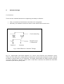
Hytec Electronics Ltd – VME64x ‘Hot Swap’ Functionality Support
•
•
•
•
•
•
Fully VME64x (i.e. VITA 1.1-1998 VME64 Extensions Standard) compliant.
Allows Carrier Card Replacement without the need to power down its IOC.
Allows Any IP Replacement without the need to power down its IOC.
Completely Safe – all hardware is design protected hot swap safe.
Hytec Electronics Ltd provided drivers will automatically re-instate the new hardware.
No need for new code development from the end user.
Provides High System Availability and Increased System Uptime.
HYTEC Head Office
HYTEC Leicester Office
Post : 5 Cradock Road, Reading, Berkshire, RG2 0JT,
England.
Phone : +44 (0)118 9757770
Fax : +44 (0)118 9757566
Post : 64 Amy Street, Leicester, LE3 2FB,
England.
Phone : +44 (0)116 2630250
Fax : +44 (0)116 2630399
Email : [email protected]
1
Introduction
In this document, we discuss Hytec Electronics hardware implementation and software,
involved in supporting hot swap in Industry Pack (IP) card drivers on VME64x carrier cards
such as the Hytec8002. By hot swap, we mean the ability to simply unplug a VME64x IP
carrier card from a correctly configured and running Input/Output Controller (IOC), replace a
defective component, say one of the IP cards, on the board and replace it into the running
system. The system will recognise that a board has been removed and replaced and resume
normal operation. Hot swap capability can be very useful in increasing overall system uptime,
especially in large installations.
2
Definitions and Glossary of Terms
Term
Description
DIN-style Connector
VME board and backplane connectors, as
described in IEC 60603-2 and IEC61076-4113.
A connection from the chassis to the
building’s grounding system. This ground is
usually isolated from logic ground in the
chassis.
Mechanical Levers mounted at the ends of a
VME Board faceplate / front panel which allow
easy extraction and removal from a sub rack
without the need for any tool. These levers
are fully specified in Chapter 8 of the IEEE
1101.10-1996 Standard.
Optional sensing
versions are available which indicate when a
board is correctly seated and the levers
locked.
Input/Output Controller.
Industry Pack.
The ability to insert or withdraw boards while
the system is powered and operating without
interruption of the system operation or
damage to the system.
A VME64x board connector pin which contacts
with the backplane connector before any of
the VME64x signal pins. These early contacts
provide a pre bias voltage or Pre-Charge
Voltage (VPC)
Pre-Charge Voltage (VPC) a supply voltage
which attaches before and is removed after
the main supplies and VME bus pins.
Boards
and/or
sub
rack
components
compliant with VITA 1.1-1998 VME64
Extensions Standard.
Frame Ground
Injector / Extractor
IOC
IP
Live Insertion
Pre-leading pin
VPC
VME64x compliant
3
Card Hardware to Allow Hot Swap Support
In brief Hytec Electronics Ltd carrier cards (for instance the Hytec8002) have the following
hardware features in support of their hot swap VME64x compliance.
3.1 Extra Connectors and Transition Boards
The VME64x standard provides for additional pins and connectors which allow all external
connections to be made via a transition board. This allows all external wiring to be made to
the rear of the IOC. Therefore there is nothing to disconnect and nothing to inhibit easy carrier
card replacement.
3.2 Pre-Charge Voltage (VPC)
Certain ground and supply pins (known as Pre-leading Pins) on the VME64x connectors are
longer than the rest, allowing them to connect earlier during insertion. This early voltage
supply, specifically known as the Pre-Charge Voltage or VPC, is used as a power up the carrier
card’s Hot Swap Voltage Controller and VME Bus buffer ICs. The Hytec Electronics Ltd carrier
cards use a Summit Hot Swap Controller and dual supply buffers. These dual supply buffers
on detection of VPC drive the VME bus to the safe tri-state condition before it is actually
connected. The hot swap controller awaits the LI/I signal from the VME back plane then run
the powers up sequence, generate an on-board reset and then finally release the tri-state on
the VME bus buffers. The VPC longevity is used in a reverse manner when removing a carrier
card.
3.3 Locking Injector / Extractor Position Sensing Handle
VME64 has always used special carrier card handles which allow easy, reliable extraction and
insertion without the need for any additional tools. The Hytec Electronics Ltd range of VME64x
carrier cards are equipped with sensing injector/Extractor Handles. They provide a low level
(ground) when the card is correctly seated and the ejector locked in, and a high (pull up from
VPC) as soon as the ejector is unlocked. The Summit Hot Swap Controller can directly accept
these signals and responds to them in a similar way to a VPC removal or detection. This gives
an extra level of warning and protection to the hot swap hardware and applications. This is an
option of VME64x compliance, which Hytec Electronics Ltd fits as standard for the extra
reliability and safety of its hot swap range.
3.4 Electro-Static Discharge
The Hytec Electronics Ltd range of VME64x carrier cards are designed to support safe electrostatic discharge via two sources…
1. The carrier cards have a bottom PCB edge is exposed metal (known as a ‘printed wiring
strip’).
2. The carrier card front panel has guide pins both top and bottom to provide additional
discharge sources through the guide pin sockets in the IOC.
The carrier cards are fitted with 2.2 MegOhms discharge resistors to provide safe discharge
paths via any of the above drain sources. This safely discharges the carrier card during any
hot swap.
3.5 Front Panel Display
VME64x compliance demands certain Front Panel LEDs and defined operation.
Hytec
Electronics Ltd range of carrier cards fully supports this with its ‘VME’ green LED and ‘NOT
CONFIGURED’ blue LED.
4
Software Basic concepts and restrictions
Assuming that the hardware is hot swappable, i.e. it adheres to the VME64x standard (at least
for the most part, see section XX for slight deviations from the standard that can be
accommodated in software). Note that only the carrier card, but not the IP card hardware,
need conform to the standard. If the IP driver software is correctly written, any IP card will be
hot swappable if it is mounted on a hot swappable carrier card such as the Hytec 8002 carrier
card.
In general, the modified drvIpac software supports scheduled and unscheduled hot swap
events. In scheduled hot swap, the user calls the routine ipacHSRemove before physically
removing the carrier card from the VME system. This allows the drivers to shut down the
hardware before the board is removed. This can allow the hardware to bring itself into a state
which suitable for swapping out.
In unscheduled hot swap, the card is simply removed without any warning to the software
system. If boards are to be removed from and inserted into a running system at any time, this
is possible and supported by Hytec Drivers and Hardware but poses some problems for the
software (see restrictions below).
In this document, we restrict ourselves to the case where we want to replace a faulty piece of
equipment in a running system. We therefore assume that:
Every VME slot must have a carrier board with functionally the same hardware before and
after the swap.
This restriction still ALLOWS the following swaps…
1. The replacement of a faulty IP card with a functional equivalent.
2. The replacement of a faulty carrier card.
3. Multiple carrier cards can be removed from the system at any given point in time.
It is legitimate to remove two or more carrier cards, replace any number of IP cards with
functional equivalents on the removed carriers, and then to replace the carriers into the
identical VME slots.
This restriction DISALLOWS the following swaps…
1. Moving of a carrier card from a VME slot n to m.
2. Adding an IP card to an empty IP slot on a carrier.
3. Adding a new VME64x carrier card to the system.
If any of these operations need to be performed, then the system will need to be reconfigured,
which typically requires at least a reboot of the IOC.
5
Software Design
5.1 Overview
There are two essential elements to supporting hot swap in software…
•
•
First, a removal and reinsertion event has to be recognised.
Secondly, the software must know how to react when these events occur.
Carrier status flag
XXX
YY
Y
Broad Presence
(1=Removed)
Removal
Insertion
Fig 5.1 Board Removal / Insertion Timings
Fig 5.1: approximate time-state diagram of a carrier card removal and reinsertion event.
There is a time delay when using polling to determine removal and reinsertion events, marked
as XXX for removal and YYY for reinsertion. The delay marked XXX can affect system integrity
if a driver attempts to access a carrier after it has been removed, but before this has been
detected by the carrier polling task.
5.2 Detecting Card Removal
There are two techniques for detecting the removal of a carrier card.
5.2.1 Interrupt
According to the VME64x specifications, a carrier should generate an interrupt when the card
is withdrawn. When the handles of the carrier card have been flipped up, but before the card
can be removed completely from the crate, the card will generate an interrupt. The VME64x
specifications furthermore state that the VME slot number should be put on the bus by the
card. In this way, the processor can quickly determine when which card is being removed.
Often IP cards on the carrier will generate their own interrupts for their own functionality. It is
necessary for the carrier to have its own interrupt vector to handle the removal event. It is
advisable to choose a higher priority for the card removal interrupt level than for the IP
interrupt levels.
In this scenario, the card removal interrupt service routine (ISR) sets a flag for the presence
of each carrier card. The IP driver routines check the status of this flag before accessing the
hardware in the usual way.
Note that this does not guarantee trouble free operation when removing a carrier card
because the checking of the carrier status flag and hardware register access cannot be
performed as an atomic operation. For example, a bus error can occur in the following case:
The IP driver checks the carrier present flag and finds the card to be present (flag=true).
Right after this, the card is removed, generating an interrupt. As a consequence, the high
priority interrupt handler sets the carrier flag to false. Once the interrupt handler exits, the IP
driver resumes running. If it now accesses the non-existent hardware registers in the normal
way (i.e. without using vxMemProbe()), it will terminate with a bus error. While this scenario
will be very rare, it cannot be fully excluded.
5.2.2 Poll and Probe
If a carrier card does not generate an interrupt on its removal, this event can nevertheless be
recognised by periodic polling. This method can be made to work reliably if…
1. The polling task runs at a higher priority than any other task accessing the hardware to
be hot swapped.
2. The driver routine accesses the hardware by using vxMemProbe().
Condition 1 ensures that the data flags signalling the absence of a board are not accessed
when the polling task is updating them. This is a mutex on the shared "presence flag" data
based on task priority. Condition 2 ensures that a bus error will not occur if the hardware is
accessed after a card is removed just after periodic polling has found it to be present (see the
delay marked with XXX in figure 5.1).
5.3 Detecting Card Insertion
The VME64x specification requires reinsertion of a board to be detected by polling. This is best
performed by a high priority task at the carrier level. The IP driver level must check the carrier
status flag immediately before accessing hardware registers in order to avoid a bus error. The
delay in the detection of a reinsertion event is not critical to the correct functioning of the
system (see figure 5.1).
5.4 Acting on Card Removal and Reinsertion
The IP driver routines should check for the existence of the hardware before accessing
hardware registers. A copy of the hardware registers value should be kept in RAM for each
hardware device.
When the hardware has been removed, the routines should return a status value indicating
the fact to the EPICS record level. Upon reinsertion, the driver should reinitialise the hardware
Register set from the previously saved values in RAM where this makes sense.
5.5 Discussion
Note that, in principle, carrier card polling or interrupt handling is not necessary if the IP driver
level uses vxMemprobe() for all hardware access. However, it is more efficient to handle
removal and reinsertion events at the carrier board level rather than for each IP card. In
addition, it is advantageous in terms of portability for the IP driver to be able to question the
carrier for its existence in the system, regardless of how board removal and reinsertion events
are detected. For this reason, the drvIpac header file has been extended with a query function
ipmCarrierIsPresent(). In addition, IP drivers should access hardware registers using the
VxMemProbe() function to avoid bus errors.
6
Acknowledgements
Steve Hunt is the man who first wrote hot swappable EPICS drivers. This document is the
result of useful discussions with him. Of course, all errors are entirely mine.
W Scott and Dave Brownless who developed the majority of the hardware drivers for Hytec
Electronics Ltd.
Melvyn Newman and Alan Burley who developed the majority of the actual hardware for Hytec
Electronics Ltd.
7
Bibliography
For much documentation about EPICS, including a list of
all EPICS supported hardware, see the EPICS homepage
at http://www.aps.anl.gov
[1] The EPICS IPAC drvIpac Module was written by Andrew Johnson
<[email protected]>. The homepage of this software is
http://www.aps.anl.gov/asd/people/anj/ipac
[2] The HyTec Electronics 8002 VME64X industry pack carrier board
hardware user manual can be downloaded from the Hytec web site:
http://www.hytec-electronics.co.uk
[3] The HyTec VICB8002 drvIpac driver user manual can be downloaded
from the Hytec web site: http://www.hytec-electronics.co.uk
[4] VME64x Live Insertion System Requirements VITA 1.4-200x
web site: http://www.vita.com
[5] Summit Microelectronics Inc S39421 Hot Swap Voltage Controller Datasheet 2004 9.1
1/23/01 web site: http://www.summitmicro.com