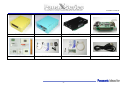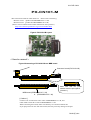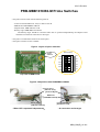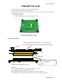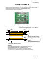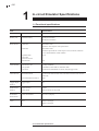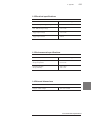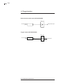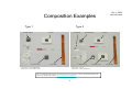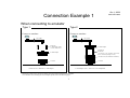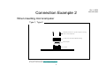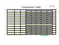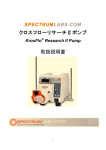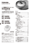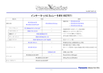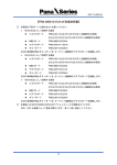
1
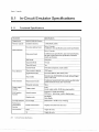
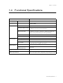
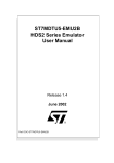
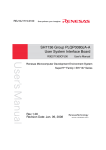
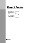
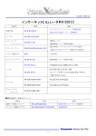
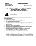
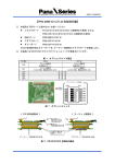
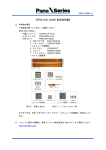
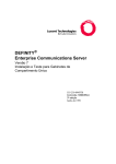
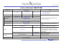
No.SS08-21CB6-0E
In-Circuit Emulator MN101CB6
Product Name
ICE
Probe set
Connector board
MBB board
Product Number
In-Circuit Emulator Specification
PX-ICE101C/E
PX-ICE101C/D
PX-ICE101C/E-PLUS
---
PRB-CN101-M
PRB-CN5-101(2)
---
-> PX-ICE101C/E-PLUS
For other product type supported by this board,
PRB-MBB101CB6-M
refer to the instruction.
PRB-ADP101-32-M
PRB-DMY101CB6-M
Product of TOKYO ELETECH CORPORATION
PRB-FAD-32BK
Instruction
PX-IFC-PCC-6
---
Compliant with PCMCIA Ver2.1/JEIDA Ver4.2
PX-IFC-PCI-6
---
Compliant with PCI2.1 of PCI-SIG standard.
When using the Low profile the PCI with
small-footprint PC's, replace the bracket by
provided one.
---
USB20C10B
PX-SDX101C00-0P0*
---
Compliant with USB1.1/2.0
PanaX Series Debugger
Debugger
PX-DBF101C00-0P0*
C Compiler/Assembler
-> PX-ICE101C/D
-> PX-ICE101C/E-Lite
PX-PRB101CB6-Y00*
ICE CONNECTOR
Interface
PX-ICE101C/E-Lite
No set
Adapter board
Dummy target board
Note
Debug Factory® Builder
PX-ICC101C00-0P0*
-1-
No.SS08-21CB6-0E
PX-ICE101C/D
PX-ICE101C/E
PX-ICE101C/E-Lite
PX-PRB101CB6-Y00*
PRB-FAD-32BK
PX-IFC-PCC-6
PC-IFC-PCI-6
USB20C10B
-2-
014-70E-124A1
PX-CN101-M
This board can be used for PX-ICE101C/E. Please refer to following.
MN101C series (product No.PRB-MBB101C***-M)
MN101E series (product No.PRB-MBB101E***-M)
(Please visit our website for the latest information on the product.)
http://www.semicon.panasonic.co.jp/e-micom/index.html
Figure1.PX-CN101-M Layout
< How to connect >
Figure2.Connecting a PX-CN101-M to a MBB board
Connector board (PX-CN101-M)
Make sure that the points
marked would be put together.
[ Caution1 ]
MBB board (PRB-MBB101C***-M)
or (PRB-MBB101D***-M)
[ Caution1 ]
Connect CNC of PX-CN101-M to CNC of PRB-MBB101***-M, and
CND of PX-CN101-M to CND of PRB-MBB101***-M.
When connecting the boards, make sure that they are connected without tilt.
If you put pressure on one side of the board, that may cause any damage to the pins.
CN101(E).doc
091-70E-502A0
PRB-CN5-101
This board can be used for PX-ICE101C/E. Please refer to following.
MN101C series (product No.PRB-MBB101C***-M)
MN101E series (product No.PRB-MBB101E***-M)
(Please visit our website for the latest information on the product.)
http://www.semicon.panasonic.co.jp/micom/
Figure1.PRB-CN5-101 Layout
< How to connect >
Figure2.Connecting a PRB-CN5-101 to a MBB board
Connector board (PRB-CN5-101)
Make sure that the points
marked would be put together.
[ Caution1 ]
MBB board (PRB-MBB101C***-M)
MBB board (PRB-MBB101E***-M)
[ Caution1 ]
Connect CNC of PRB-CN5-101 to CNC of (PRB-MBB101C***-M), (PRB-MBB101E***-M) and
CND of PX-CN101-M to CND of (PRB-MBB101C***-M), (PRB-MBB101E***-M).
When connecting the boards, make sure that they are connected without tilt.
If you put pressure on one side of the board, that may cause any damage to the pins.
CN5_101(E).doc
078-71E-610A1
PRB-MBB101CB6-M Probe Switches
- This probe must be used with the following boards.
- Connector board: PRB-CN5-101(2) or PX-CN101-M
- MBB board: PRB-MBB101CB6-M
- Adapter board: PRB-ADP101-32-M
- Dummy target: PRB-DMY101CB6-M
The dummy target should be connected when ICE is operated independently, the adapter board
should be connected at connection to the target.
- This probe is mounted the switches for mask option.
- The option switches are not available.
Figure1. Layout of option switches
Default setting
OFF
ON
Option
switches
OP0
OFF
OP1
OFF
OP2
OFF
OP3
OFF
OP4
OFF
OP5
Top view of MBB board
Figure2. Composition with PRB-MBB101CB6-M
Connector board
[PRB-CN5-101(2)]
([PX-CN101-M])
MBB board
[PRB-MBB101CB6-M]
Dummy target
[PRB-DMY101CB6-M]
- When ICE is operated independently.
Flexible adapter board
[PRB-ADP101-32-M]
- At connection to the target
MBB_CB6(E)_a1.doc
08X-72E-638A0
PRB-ADP101-32-M
When connected to the target, use this board with MBB board.
This board can be used with the following boards.
(The product type is subject to change without prior notice. The latest information should be
confirmed on our web site.)
- PRB-MBB101CD0-M
Improper matching may cause any damage to the ICE.
Figure 1.Adapter Board Layout
< How to connect >
Connector board : PRB-CN5-101(2)
or
PX-CN101-M
The connector board, which can be used by the kind changes.
MBB board
Make sure that the points marked
would be put together.
[ Caution 1 ]
Adapter board : PRB-ADP101-32-M
[ Caution1 ]
Connect CNE of MBB board to CNE of PRB-ADP101-32-M, and
CNF of MBB board to CNF of PRB-ADP101-32-M.
When connecting the boards, make sure that they are connected without tilt.
If you put pressure on one side of the board, that may cause any damage to the pins.
adp32pin(E).doc
077-73E-605A0
PRB-DMY101CB6-M
Dummy target boards differ depending upon the models. This board can be used for only MN101CB6.
When unconnected to the target, use this board with the PRB-MBB101CB6-M.
Improper matching may cause any damage to the ICE.
Figure 1.PRB-DMY101CB6-M Layout
< How to connect >
Connector board: PRB-CN5-101 (2)
or
PX-CN101-M
MBB board: PRB-MBB101CB6-M
Make sure that the points marked
would be put together.
[Caution1]
Dummy target: PRB-DMY101CB6-M
[Caution1]
Connect CNE of PRB-MBB101CB6-M to CNE of PRB-DMY101CB6-M, and
CNF of PRB-MBB101CB6-M to CNF of PRB-DMY101CB6-M.
When connecting the boards, make sure that they are connected without tilt.
If you put pressure on one side of the board, that may cause any damage to the pins.
dmyCB6(E).doc
232
1
In-circuit Emulator Specifications
1-1 Functional specifications
Item
Specifications
Devices
MN101CXX Series
Memory size
Emulation memory
256 Kbytes (standard)
480 Kbytes (maximum)
Break function
ROM break
Maximum 4 events
Condition: Area and pass count specification
Maximum 4 events
Condition: Specifications of area and pass count, bit mask, read/write/
access, match/mismatch, AND condition
2-level
RAM break
Sequential break
Trace break
RAM access break
External break
1-bit
Trace function
Trace memory size
Trace get data
Trace mode
511 steps (standard)
ROM address, RAM address, RAM data, R/W
Normal mode, ROM/RAM area mode, delayed trigger mode
Timer function
Measurement mode
Time measurement resolution
Execution time measurement mode, maximum execution time measurement mode
100ns
Trigger output
function
Trigger output
One
RAM monitor
function
Sample memory
Display mode
32 bytes
Dump list mode, bit map mode
Performance
measurement
Profile measurement
Run ratio (%) display
Clock
OSCI
XI
Emulator and target
Emulator and target
In-circuit Emulator Specifications
9. Appendix
233
1-2 Electrical specifications
Parameter
Rating
Emulator and probe supply voltage
0.5 to 6.0V
EXT. BREAK input voltage
−0.3 to 5.5V
Trigger output voltage
−0.3 to 5.5V
Trigger output current
±10mA
1-3 Environmental specifications
Rating
Parameter
Operating temperature
Storage temperature
10°C to 30°C
0°C to 45°C
Operating humidity
Storage humidity
20% to 80%
90% or less
1-4 External dimensions
Length × width × height
130 × 100 × 40mm
In-circuit Emulator Specifications
234
1-5 Target interface
External break probe input (OPTION PROBE)
74HCT 541
OPTION PROBE
(yellow)
External break signal
Trigger output (OPTION PROBE)
74HCT 541
OPTION PROBE
(blue)
In-circuit Emulator Specifications
Trigger signal
Chapter 1 Overview
1.4 Functional Specifications
Parameter
Specifications
Memory capacity
Emulation memory
1 MB (ROM, RAM)
Mapping
Measurement block
Switchable between emulation memory and external memory
in bank (64KB)
Break functions
Software break
Up to 255 events
Execution address break
Up to 2 events
Conditions: area, pass count specification
Data access break
Up to 2 events
Conditions: area, data comparison <match/not match>, bit
mask, access specification, pass count specification
Sequential break
4 levels
Trace full break
Yes
Trace capacity
2K frames
Acquired trace data
Execution address, data address, data, access status
Trace modes
Normal mode, delayed trigger mode (Stop tracing after tracing
for 1K frame after a trigger event occurs)
Measurement mode
Execution time, Maximum execution time between events
Resolution / Maximum
measurement time
50ns/214s
Trace function
Timer function
Trigger output function
2 trigger pins (only pulse output)
Watch output function
All address spaces of the microcomputer
(Note: The target software temporarily stops during accessing)
Functional Specifications 5
Oct 1, 2008
085-72E-630A0
Flexible Cable Adapter
User’s Manual
Software & Solutions Development Center
Corporate System LSI Division
Semiconductor Company
Panasonic Corporation
Oct 1, 2008
Introduction
085-72E-630A0
- Composition of Flexible Cable Adapter
There are two composition types by microcomputer’s packages.
Type 1. Socket cover (for emulator connection) is soldered to the EXB adapter.
Type 2. EXB adapter and socket cover (for emulator connection) are independent.
- Contents confirmation
Please check the package components with Composition Examples and Composition Table.
- Connection
When connecting to the emulator, please refer to Connection Example 1.
When inserting the microcomputer, please refer to Connection Example 2.
- Detailed Socket information
For more information about Socket (Technical drawings, Foot patterns, Cautions, Technical
Information etc.), please visit the following website: Tokyo Eletech Corporation
http://www.tetc.co.jp/e_index.htm
1
Oct 1, 2008
Composition Examples
Type 1
085-72E-630A0
Type 2
b. EXB Adapter
e. Socket
f. Socket Cover
d. Guide Pin
a. KC Cable
b. EXB Adapter
f. Socket Cover
long screws : for b.EXB Adapter
short screws : for f. Socket Cover
c. Socket Cover
long screws : not use
short screws : for f. Socket Cover
For more information about Socket (Technical drawings, Foot patterns, Cautions, Technical Information etc.),
please visit the following website: http://www.tetc.co.jp/e_index.htm
2
e. Socket
a. KC Cable
Oct 1, 2008
Connection Example 1
085-72E-630A0
When connecting to emulator
Type 1
Type 2
Connect to emulator
Connect to emulator
a. KC Cable
a. KC Cable
Fit and fix
b. EXB Adapter to the
e. Socket with screws.
b. EXB Adapter
d. Guide Pin
(Fit and fix
c. Socket Cover (for emulator connection)
to the e. Socket by turning a screw.)
b. EXB Adapter
c. Socket Cover (for emulator connection)
e. Socket
e. Socket
* Socket Cover is soldered to b. EXB adapter.
* b. EXB Adapter and c. Socket Cover are independent.
Please use f. Socket Cover (for microcomputer inserting) when inserting the microcomputer.
For connection when inserting the microcomputer, please refer to the following page.
3
Oct 1, 2008
Connection Example 2
When inserting microcomputer
Type 1, Type 2
Fit and fix f. Socket Cover (for microcomputer inserting)
to the e. Socket with screws.
f. Socket Cover (for microcomputer inserting)
Microcomputer
e. Socket
For more information about Socket (Technical drawings, Foot patterns, Cautions, Technical Information etc.),
please visit the following website: http://www.tetc.co.jp/e_index.htm
For emulator connection, please refer to the previous page.
4
085-72E-630A0
Oct 1, 2008
Composition Table
085-72E-630A0
EXB Sets
Model Name
Target Package
a. KC Cable
b. EXB Adapter
PRB-FAD-32BK
SSOP032-P-0300
KC200-50N (n=1)
PRB-EXB-32BK
PRB-FAD-044SA
QFP044-P-1010
KC200-50N (n=1)
PRB-EXB-044SA
EXB-32BK-PA
c. Socket Cover (for
emulator connection)
LQFP048-P2-0707
KC200-50N (n=1)
LQFP064-P-1414
KC200-50N (n=2)
YSPACK32BK
TQFP064-P-1010
KC200-50N (n=2)
microcomputer inserting)
YSGUIDE-S
NSPACK32BK
HSPACK32BK
-------
-------
NQPACK044SA
HQPACK044SA
NQPACK048SD
HQPACK048SD
NQPACK064SA160
HQPACK064SA160
NQPACK064SD-ND
HQPACK064SD
Type 2
YQPACK048SD
YQGUIDE-S
Type 1
PRB-EXB-064SA160
-------
-------
PRB-EXB-064SD
EXB-064SD-PA
PRB-FAD-080SB160
LQFP080-P-1414
KC200-50N (n=2)
PRB-FAD-100SB
QFP100-P-1818
KC200-80N (n=2)
PRB-EXB-100SB
PRB-FAD-100SD
LQFP100-P-1414
KC200-80N (n=2)
PRB-EXB-100SD
PRB-FAD-112SB
LQFP112-P-2020
KC200-80N (n=2)
PRB-FAD-128SD
LQFP128-P-1818
KC200-80N (n=2)
Type 2
YQPACK064SD
YQGUIDE-S
Type 1
PRB-EXB-080SB160
EXB-080SB-PA
-------
-------
NQPACK080SB
HQPACK080SB160
Type 1
EXB-100SB-PA
EXB-100SD-PA
-------
-------
NQPACK100SB
HQPACK100SB
Type 2
YQPACK100SD
YQGUIDE-S
NQPACK100SD-ND
HQPACK100SD
PRB-EXB-112SB
Type 1
EXB-112SB-PA
-------
-------
NQPACK112SB
HQPACK112SB
PRB-EXB-128SD
EXB-128SD-PA
Composition
Types
Type 1
EXB-064SA-PA
PRB-FAD-064SD
f. Socket Cover (for
PRB-EXB-048SD
EXB-048SD-PA
PRB-FAD-064SA160
e. Socket
Type 2
EXB-044SA-PA
PRB-FAD-048SD
d. Guide Pin
Type 2
YQPACK128SD
YQGUIDE-S
NQPACK128SD
HQPACK128SD
For more information about Socket (Technical drawings, Foot patterns, Cautions, Technical Information etc.), please visit the following website: http://www.tetc.co.jp/e_index.htm
For composition example and connection example, please refer to the appropriate composition type.
5