1
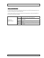
Page 1
SEM-SAFE DEEP FAT FRYER WATERMIST SYSTEM
USER MANUAL
TABLE OF CONTENTS
Part 1
Design data
Page 2
System Description
Page 3
Component Description
Page 5
System Activation and Re-establishing
Page 9
Part 2
Part 3
Part 4
Part 5
Six Month Check
Page 12
Part 6
Spare Parts
Page 17
Drawings
Page 18
Component List
Page 19
Component Data Sheets
Page 20
Part 7
Part 8
Part 9
Part 1. Design data:
User Manual, Issue no. 1
20. September 2003
Page 2
SEM-SAFE DEEP FAT FRYER WATERMIST SYSTEM
Supply Voltage:
Power consumption:
24 V DC UPS
50 VA
Initial operation pressure at nozzle heads:
Test pressure:
145 bar decreasing
218 bar
Unit capacity:
1 unit consisting of;
H2O cylinders: 1 pc. containing 8 l
N2 cylinders: 1 pc. containing 8 l / 145 bar
Nozzle nominal capacity:
2 x Main nozzle type DFF 36, each k-factor = 0,47
1 x Main / cooling nozzle type DFF 27, each k-factor = 0,28
System water capacity:
8 litres
Water quality required:
De-ionizated freshwater is recommended. However, potable freshwater may be used.
*Potable water which comply with the EU-order 80/778/EEC
* If the system is for Lloyds Register classification the system has to be filled with de-ionizated
water under all circumstances. Therefore it has to be controlled by each check that fresh water/sea
water has not been filled into the system.
User Manual, Issue no. 1
20. September 2003
Page 3
SEM-SAFE DEEP FAT FRYER WATERMIST SYSTEM
Part 2. System description:
The system detailed is our Sem-Safe Fire Extinguishing Watermist System for fire fighting of
single vat Deep Fat Fryer units.
General Plant Description:
See drawing no. DFF-2108 HEAT / PUSH, rev. 0.
The Sem-Safe Watermist System designed for fire protection of the vessels deep fat fryer units
listed hereunder, is consisting of a separate self-contained unit, and consisting of 1 H2O and 1 N2
high pressure cylinders. The cylinders may be installed in a stainless steel enclosure. The system
is designed for automatic and manual operation.
The plant covers the following deep fat fryers located in the mentioned areas;
- Main Galley
The Sem-Safe Watermist DFF fire-extinguishing System is designed for fire protection of deep
fat fryer units, based on fire-extinguishing in deep fat fryer oil with a very fine high-pressure
water mist.
The DFF fire-extinguishing system is a pressure vessel based system consisting of two highpressure cylinders as a “stand alone” system as a separate fire-section. The extinguishing media
is freshwater.
The DFF fire-extinguishing system is consisting of the following major items;
- Pressure vessel unit; N2 and H2O high pressure cylinders with valves and release unit,
- Sem-Safe DFF nozzle heads and pipe system,
- Pulse valve,
- Control unit,
- Release push-button,
- Heat detector,
- Alarm indicator.
Dimensioning of the unit
Dimensioning of the system is based from our Deep Fat Fryer performance tests, carried out at
the Danish Institute of Fire and Security Technology (DIFT) in March 2003. The system is
tested in accordance with the ISO 15371:2000 standard.
Dimensioning of the system is based on protection of one deep fat fryer (single vat). The system
capacity is 8 litres and designed to provide water to the DFF nozzles for fire-protection in
approximately 10 minutes.
User Manual, Issue no. 1
20. September 2003
SEM-SAFE DEEP FAT FRYER WATERMIST SYSTEM
Page 4
The water consumption for one single vat deep fat fryer is 8 litres freshwater in approximately
10 minutes.
Extinguishing times and capacities required for split vat deep fat fryer units and multiple vat
deep fat fryer units, are different from single vat deep fat fryer units.
Power supply
The DFF control unit is designed for a 24 V DC / 50 VA power supply. The power supply is
provided from the vessel.
Water supply
The H2O high pressure cylinder, 8 litres, is recommended to be filled with de-ionizated freshwater
after any release.
Water supply to the DFF fire-extinguishing system is recommended to be filled with de-ionizated
freshwater. If de-ionizated freshwater is not available potable freshwater which comply with the
EU-order 80/778/EEC, may be used.
Activation of the system
The DFF system is designed for manual operation, activating a “Watermist release” push-button,
and for automatic operation from a heat detector placed in the DFF hood. The system can also be
emergency released. See detailed description in chapter 4.
Unit location
The Sem-Safe Watermist pressure vessel unit, control unit and operations should be located
outside the protected areas for safe and easy access even during a fire in the protected space
(galley).
Nozzle location
The SEM-SAFE Watermist Deep Fat Fryer nozzle heads are mounted inside the Deep Fat Fryer
hoods in an even grid right below the ceiling, as show on the examples in the enclosed drawing
DFF-2103.
The actual position of the nozzles in the individual Deep Fat Fryer hoods are depending of the
various sizes of the Deep Fat Fryers, and to a certain extend of the actual shaping of the Deep
Fat Fryer hoods.
User Manual, Issue no. 1
20. September 2003
Page 5
SEM-SAFE DEEP FAT FRYER WATERMIST SYSTEM
Part 3. Component description:
Pressure vessel unit; N2 and H2O high-pressure cylinders with valves and release unit
The pressure vessel unit consists of two high-pressure cylinders, one cylinder for water and one
cylinder pressurised to 145 bar with Nitrogen (N2) working as prime mover of the water in the
water cylinder. Each cylinder is having content of 8 litres.
The N2 cylinder is fitted with a cylinder normally open shut off valve, a contact pressure gauge
solenoid valve release unit, high pressure flexible hose, and a manual release lever.
When the release of the N2 cylinder has taken place the N2 is pressing out the water in the water
cylinder to the SEM-SAFE DFF Watermist nozzles. The pressure in the system will reduce
gradually as the system is using water, until the cylinders are emptied.
A pressure gauge is mounted on the N2 cylinder, and a pressure switch controls the pressure in the
cylinder. If the cylinder for some reason should lose pressure, an alarm is raised to the control
system.
The H2O cylinder is mounted with a cylinder adaptor and discharge pipe.
The fresh water- and nitrogen cylinders are interconnected via a 6 mm stainless steel pipe.
Further, the system is equipped with a “feed back” pressure switch, mounted in the system after
the H2O cylinder water outlet. The “feed back” pressure switch is activating when the system is
released.
The pressure vessel system can also be made with a service valve and a drain valve for testing and
service purposes. This is an option that can be chosen, and is not standard.
The unit automatically releases in the case a fire is detected in one of the Deep Fat Fryers. When
the system is activated, the N2 cylinder solenoid valve opens and nitrogen pressure will, via the 6
mm pipe connecting the two cylinders, be directed into the fresh water cylinder and subsequently
press out the water to the discharge pipe and further to the DFF section(s).
The system can also be manually released by operating the release handle on the N2 cylinder.
The unit overall dimensions are (approximately);
length = 400 mm, depth = 250 mm, height = 800 mm.
Weight of the unit (two cylinders) in stand by condition including brackets, water and N2 is
approximately 40 kg.
User Manual, Issue no. 1
20. September 2003
Page 6
SEM-SAFE DEEP FAT FRYER WATERMIST SYSTEM
Controls
The DFF control panel can be designed for automatic release from a heat detector placed in the
DFF hood and / or manual release from “Watermist Release” push-button(s), or manual release
from a release handle at the N2 cylinder.
The DFF controls are built into a separate enclosure; a DFF control box having its own separate
control for the DFF fire section.
The DFF fire-extinguishing System is released by operating a “Watermist Release” push button,
or automatically from a 150°C heat detector placed in the DFF hood.
When a “Watermist Release” push button is pressed or the heat detector has activated, a release
signal to the control box are set, and the N2 cylinder solenoid valve will open and Watermist is
released from the SEM-SAFE Watermist Deep Fat Fryer nozzle heads.
The release of the system will automatically set a signal for the operation of an audible alarm.
When the DFF fire-extinguishing System is released, the following outputs from the DFF control
box are provided;
- Signal to DFF cut-off at WM release (potential free signal)
- Signal to ventilation cut-off at WM release (potential free signal – as a pulse signal)
- Signal to Fire damper cut-off at WM release (potential free signal)
- “System released” / “System Failure” signal out (potential free signal)
- Signal out to close 24VDC solenoid valve ~ 20 sec. after WM release
- 24 V DC out put to Alarm indicator in galley ~ 70mA
- 24 V DC out put to the N2 release solenoid valve ~ 14W
Controls for the automatic release and control of the unit as well as “System Failure” alarm
indications with alarms for;
− Low pressure in the N2 cylinder; at falling pressure to ~ 120 bar
− No power at system
− “System released”
− Auto Release switch in “OFF” position
If the system is equipped with test and drain valve, these will also raise an alarm if out of normal
standby position.
When Watermist to the Deep Fat Fryer has been released, the high-pressure cylinders should
allow to be fully emptied.
The DFF control unit enclosure is made for 24 V DC power supply, 50 VA, in IP54 protection.
Calculated power consumption at full load is ~ 2 Amperes.
Pulse Valve
User Manual, Issue no. 1
20. September 2003
SEM-SAFE DEEP FAT FRYER WATERMIST SYSTEM
Page 7
The Pulse valve is a normally open directional high-pressure electrically operated solenoid
valve.
The Pulse valve is normally open and allows for water to the main DFF nozzles. A timer
automatically closes for the Pulse valve ~15 seconds after release of the system – after the fire
has been extinguished – hereafter only the cooling DFF nozzle is active, impeding the DFF oil to
re-ignite.
The Pulse valve made in stainless steel, is supplied loose for installation into the pipe system.
Alarm indicator
An audible alarm indicator for mounting inside the galley is supplied. The alarm indicator will
activate when the system is released.
The alarm indicator is for 24VDC supply ~ 70mA, and has a high sound out put of 102 dB(A).
the sound signal can be changed for 11 different signals.
Pipe System
The pipes and necessary fittings are supplied in stainless steel AISI 316, and the pipes are to be
joined by compression fittings.
The cutting ring fittings are of DIN 2353 standard (ISO 8434-1).
The main pipeline size and length is determined by the calculated pressure drop. Normally pipe
dimensions of Ø15,0 x 1,5 mm or Ø 10,0 x 1,0 mm are installed.
The main pipeline is branched into a distribution pipeline normally Ø 6,0 x 1,0 mm installed
right above the Deep Fat Fryer.
The Sem-Safe Watermist nozzles are connected to the distribution line with 6 mm compression
fittings.
The pipes are to be installed in noise and vibration free heavy-duty pipe hangers for supporting
the tubes with approx. 1,5 metres interval.
Necessary stainless steel pipe (AISI 316) and compression fittings are supplied.
All pipes are supplied with 3. 1. B certificate.
Heat detectors for automatic activation
User Manual, Issue no. 1
20. September 2003
Page 8
SEM-SAFE DEEP FAT FRYER WATERMIST SYSTEM
For automatic systems only. We have programmed the system PLC control to release the system
automatically by activation from a heat detector(s).
We have based the fire detection system for the automatic release from heat detectors only,
dedicated to the individual objects (Deep Fat Fryers) protected. We have used Salwiko SWM1KL/150 heat detectors in IP 67.
The signal from an activated heat detector is controlled in the PLC, and this signal is treated to
give a signal to release the dedicated section.
That is, if a heat detector dedicated to an object activates, the N2 cylinder release solenoid valve
(and the dedicated section solenoid valve opens) and the Watermist system is released.
We suggest the following coverage with heat detectors of the respective objects protected;
For each of the Deep Fat Fryers we would place one heat detector, placed centrally above the
fryer in the Deep Fat Fryer hood .
Where more than one heat detector covers an object, these are to be connected in parallel.
Sem-Safe Watermist Nozzles
See drawing no. DFF-1708, rev. 0, and DFF-1709, rev. 0, and DFF-2103, rev. 0.
The SEM-SAFE Deep Fat Fryer nozzle heads are of open nozzles type;
- DFF Nozzle 27 (one main and one cooling micro nozzle in same nozzle head), to be mounted
in the centreline above the Deep Fat Fryer
- DFF Nozzle 36 (two main micro nozzles in same nozzle head), to be mounted in line with
the fryer ends, max. 375 mm from the centreline, above the Deep Fat Fryer.
The SEM-SAFE Deep Fat Fryer nozzle heads are made in brass with a strong pewter-nickel
alloy surface treatment, giving the nozzle head a “stainless steel look”.
The Watermist micro nozzles are made in stainless steel AISI 316, and are of the same type as
the SEM-SAFE Watermist nozzles used in all our SEM-SAFE Watermist Systems.
Total amount of SEM-SAFE Deep Fat Fryer nozzle heads included are 3.
User Manual, Issue no. 1
20. September 2003
SEM-SAFE DEEP FAT FRYER WATERMIST SYSTEM
Page 9
Part 4. System Activation and Re-establishing:
Activation of the system
The DFF system is designed for automatic release from a heat detector placed in the DFF hood
and / or manual release from a “Watermist Release” push-button. The system can also be
emergency released from a manual release handle at the N2 cylinder.
For automatic activation, the system receives an incoming signal from a heat detector placed
locally in the deep fat fryer hoods, which automatically will release watermist to the dedicated
deep fat fryer.
In case of a fire, a signal provided by the locally placed heat detector, will be transferred to the
PLC in the control panel.
The PLC operates N2 solenoid release valve (and the dedicated section valve), and provides a
signal for the Safety Management System, as well as a signal to shut down the exhaust fan for
the actual room/galley hood.
A facility for switching “OFF” automatic activation mode is established. In the front of the unit
control panel an “AUTO RELEASE” switch in built in. The switch has three positions; “AUTO
RELEASE” “ON” and “OFF”, and “AUTO”. When in “ON”, the system can be released
automatically – from the heat detectors and from the locally placed “Watermist Release” pushbutton(s).
When in OFF”, the system can only be released from the locally placed “Watermist Release”
push-buttons or from the emergency release lever on the N2 cylinder. When the “AUTO
RELEASE” switch is left in OFF” position, an alarm will be raised = “System Failure”.
If the switch is in “AUTO” position, operating power is removed from the system solenoids and
the prime mover N2 to the system is actually stopped. However, the residual pressure in the
water cylinder will for some time still force water out of the nozzles however at a reduced
pressure.
Manual activation
In case of a fire, the system is “manually” operated by pressing a “Watermist Release” pushbutton, locally placed outside the protected space.
By pressing this “Watermist Release” push-button, the system is set in operation immediately;
Watermist is released from the SEM-SAFE Watermist Deep Fat Fryer nozzle heads.
For emergency activation of the system, in case of an error in the operation system, (the section
valves can be emergency operated by opening the by-pass valve built in each section valve), and
by manually operating (pulling) the emergency release lever on the N2 cylinder placed in the
stainless steel unit enclosure.
User Manual, Issue no. 1
20. September 2003
Page 10
SEM-SAFE DEEP FAT FRYER WATERMIST SYSTEM
Note: At emergency release of the system, ventilation shall be shut down and dampers shall be
closed, and power to the deep fat fryer should be cut off as far possible.
After releasing
When Watermist to the Deep Fat Fryer once has been released for fire-fighting, the system
should be allowed to run the full fire-extinguishing sequence, i. e. the high-pressure cylinders
should be allowed to be fully emptied.
If the system is equipped with a test valve, it is possible to close for water to the DFF nozzles, by
manually closing the test valve.
If the system is equipped with a three position selector switch (note; this is only for systems
having automatic release from a heat detector) it is possible to remove operating power from the
system solenoids by turning the switch to “AUTO” position. This operation will close the system
solenoid N2 release valve and the prime mover N2 to the system is actually stopped. However,
the residual pressure in the water cylinder will for some time still force water out of the nozzles
however at a reduced pressure.
When a fire has been extinguished and the high-pressure cylinders are fully emptied, the system
should be reset. Basically this means refilling of the N2 and H2O high-pressure cylinders.
After any release, the N2 cylinder must be replaced or refilled with new nitrogen cylinders of 145
bar pressure, in order to reset the unit. Any release means that even if the N2 cylinder is not
emptied it must be replaced / refilled at all times. Filling the N2 cylinder with new N2 can be done
at a recognized filling station. A cylinder refilling procedure for information may be forwarded
upon request.
For the reassembly / disassembling of the N2 cylinder release unit, see data sheet no.: 01-71720003.
Re-fill the H2O cylinder with de-ionizated fresh water, as described hereunder;
See drawing DFF 1710. Water is filled manually through the 1/8” BSP threaded port, until water
appears from the - untied - H2O high-pressure cylinder outlet fitting.
Tighten again the H2O high-pressure cylinder outlet fitting after the H2O cylinder is full.
Water supply to the DFF fire-extinguishing system is recommended to be filled with de-ionizated
freshwater. If de-ionizated freshwater is not available potable freshwater which comply with the
EU-order 80/778/EEC, may be used.
Restart ventilation when this has been shut off during the release of the system.
Re-establish fire damper when this has been shut off during the release of the system.
Reset DFF heating element when this has been shut off during the release of the system.
User Manual, Issue no. 1
20. September 2003
SEM-SAFE DEEP FAT FRYER WATERMIST SYSTEM
Page 11
Check that the “System Ready” lamp indication lights up (only automatic systems has “System
Ready” lamp).
User Manual, Issue no. 1
20. September 2003
Page 12
SEM-SAFE DEEP FAT FRYER WATERMIST SYSTEM
Part 5.: Six month check
To ensure that the system always will function satisfactorily, a periodic check programme has to be
carried out according to the mentioned procedure.
After having executed the procedure the individual check programmes are dated and signed for in
the enclosed Test Procedure Log Sheet.
PART 5.1 Visual inspection of N2 / H2O cylinder unit
EVERY SIX
MONTH CHECK
User Manual, Issue no. 1
PART 5.2 Check alarms
Simulate automatic release of the system from heat
detectors.
Simulate release of the system from “Release Watermist”
PART 5.4
push buttons.
PART 5.3
20. September 2003
Page 13
SEM-SAFE DEEP FAT FRYER WATERMIST SYSTEM
5.1
Visual inspection of N2 / H2O cylinder unit
Ref. drawing no. DFF-2108, rev. 1, Data Sheet DS 01-7172-1150/1300, and DS 01-6471-0150.
Precondition:
• Report time for inspection to control room.
•
Test Procedure:
1. Check that the indication lamps in control panel are OK.
2. Check that “System Ready” indication lamp lit, and “System Failure” does not lit.
3. Check that pressure indicator on N2 cylinder is above ~ 140 bar.
4. Check that “AUTO RELEASE” is “ON”.
5. Check that the bursting disc, pos. 1 on Data Sheet no. DS 01-6471-0150 is in place.
6. General check of the pipe installation, pulse valve and nozzles.
7. Check that test valve and drain valve are in closed and open position respectively, and that
the limit switches are working OK.
8. Check the leak / bleeder valve release indicator cap (green) is in place, i. e. the system has
not been released.
User Manual, Issue no. 1
20. September 2003
Page 14
SEM-SAFE DEEP FAT FRYER WATERMIST SYSTEM
5.2
Check alarms
Ref. drawing no. DFF-2108, rev. 1, Data Sheet DS 01-7172-1150/1300
Precondition:
• Report time for inspection to control room.
• Remove N2 cylinder release solenoid valve coil, Data Sheet DS 01-7172-1150/1300, pos. 4,
to prevent watermist being released.
• System in “System Ready” mode.
Test Procedure:
1. Switch the “AUTO RELEASE ON / OFF” selector switch to “OFF” position.
Observe:
•
•
•
“System Failure” indication on the unit enclosure control panel.
Indication in SMS.
Reset the system again by switching the “AUTO RELEASE ON / OFF” selector switch to “ON”,
and note that the system return to “System Ready” mode.
2. Simulate N2 cylinder low pressure alarm by removing the el-socket in the contact pressure
gauge.
Observe:
•
•
•
“System Failure” indication on the unit enclosure control panel.
Indication in SMS.
Remount the removed el-socket and the system is reset; note that the system return to “System
Ready” mode.
Re-establishing the system:
•
•
•
Remount N2 cylinder release solenoid valve coil.
Remount the removed el-socket.
User Manual, Issue no. 1
20. September 2003
SEM-SAFE DEEP FAT FRYER WATERMIST SYSTEM
5.3
Page 15
Simulate automatic release of the system from heat detectors.
Ref. drawing no. DFF-2108, rev. 1, and Data Sheet DS 01-7172-1150/1300.
Precondition:
• Report time for inspection to control room.
• Remove N2 cylinder release solenoid valve coil, Data Sheet DS 01-7172-1150/1300, pos. 4,
to prevent watermist being released.
• System in “System Ready” mode.
• Check that “AUTO RELEASE” is “ON”.
Test Procedure:
1. Simulate automatic release of the system from a random selected heat detector. Carefully
(slowly) heat up the heat detector to just above 150 ºC. (Alarm horn will activate).
Observe:
•
•
•
•
•
•
•
“FIRE” indication on the unit enclosure control panel.
That the N2 solenoid valve pulls.
That the solenoid pulse valve closes (pulls) after 15 seconds.
That the dedicated ventilation fan stops.
That the dedicated fire damper shuts down.
Alarm indicator in the galley sounds.
That the dedicated deep fat fryer shuts down.
When the heat detector again has cooled down, the system is reset; note that the system return to
“System Ready” mode.
Carry out the test over again for all the individual heat detectors.
Re-establishing the system:
•
•
•
•
Remount N2 cylinder release solenoid valve coil.
Restart ventilation when this has been shut off during the release of the system.
Re-establish fire damper when this has been shut off during the release of the system.
Reset DFF heating element when this has been shut off during the release of the system.
User Manual, Issue no. 1
20. September 2003
Page 16
SEM-SAFE DEEP FAT FRYER WATERMIST SYSTEM
5.4
Simulate release of the system from “Release Watermist” push button(s).
Ref. drawing no. DFF-2108, rev. 1, and Data Sheet DS 01-7172-1150/1300.
Precondition:
• Report time for inspection to control room.
• Remove N2 cylinder release solenoid valve coil, Data Sheet DS 01-7172-1150/1300 pos. 4, to
prevent watermist being released.
• System in “System Ready” mode.
• Check that “AUTO RELEASE” is “ON”.
Test Procedure:
1. Simulate release of the system from a “Release Watermist” push button.
Observe:
•
•
•
•
•
•
•
“FIRE” indication on the unit enclosure control panel.
That the N2 solenoid valve pulls.
That the solenoid pulse valve closes (pulls) after 15 seconds.
That the dedicated ventilation fan stops.
That the dedicated fire damper shuts down.
Alarm indicator in the galley sounds.
That the dedicated deep fat fryer shuts down.
The system is reset; note that the system return to “System Ready” mode.
Carry out the test over again for all the individual “Release Watermist” push buttons.
Re-establishing the system:
•
•
•
•
•
Remount N2 cylinder release solenoid valve coil.
Restart ventilation when this has been shut off during the release of the system.
Re-establish fire damper when this has been shut off during the release of the system.
Reset DFF heating element when this has been shut off during the release of the system.
Part 6. Spare Parts:
User Manual, Issue no. 1
20. September 2003
SEM-SAFE DEEP FAT FRYER WATERMIST SYSTEM
Page 17
Enclosed to this paragraph is our recommended List Of Spare Parts, however no Spare Parts are
included in the order.
User Manual, Issue no. 1
20. September 2003
Page 18
SEM-SAFE DEEP FAT FRYER WATERMIST SYSTEM
Part 7. Drawings:
Draw. no.
DFF-2108
DFF-2103
DFF-1708
DFF-1709
DFF-1710
DFF-2602
10003765
User Manual, Issue no. 1
LIST OF DRAWINGS
Rev.
Description
1
DFF FIRE EXTINGUISHING SYSTEM
0
NOZZLE INSTALLATION
0
DEEP FAT FRYER NOZZLE 27
0
DEEP FAT FRYER NOZZLE 36
0
ADAPTER FOR H2O CYLINDER DFF
A PUSH-BUTTON
SET OF ELECTRICAL DIAGRAM, REV. 17/6/2003
20. September 2003
SEM-SAFE DEEP FAT FRYER WATERMIST SYSTEM
Page 19
Part 8. Component List:
Enclosed to this paragraph is the Component List.
User Manual, Issue no. 1
20. September 2003
Page 20
SEM-SAFE DEEP FAT FRYER WATERMIST SYSTEM
Part 9. Component Data Sheets:
Data Sheet no.:
1
2
3
4
5
6
6A
7
8
9
10
11
12
13
14
15
16
17
18
19
20
21
22
IN 01-7172-0004
DS 01-7172-1150
DS 15-8020-0007
DS 01-3273-0140
DS 01-3272-0180
DS 15-8240-0037
DS 01-6471-0150
DS 01-3388-0000
26A
26
User Manual, Issue no. 1
LIST OF DATA SHEETS
Description
SOLENOID VALVE (PULSE VALVE)
COLSON VALVE
HEAT DETECTOR
AUDIBLE ALARM
RELEASE UNIT FOR VALVE
RELEASE UNIT GAUGE NORMALLY CLOSED VALVE
CONTACT PRESSURE N.C.
FLEX. HOSE ¼” 400 mm
HI-FLEX. HOSE ¼” FOR PILOT LINE 450 mm
SOLENOID VALVE
PNEUMATIC ARGONITE VALVE
LEAK/ BLEEDER UNIT
PRESSURE SWITCH
BRACKETS FOR CYLINDERS
CYLINDERS 8 L
20. September 2003
SEM-SAFE DEEP FAT FRYER WATERMIST SYSTEM
User Manual, Issue no. 1
Page 21
20. September 2003