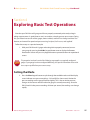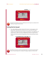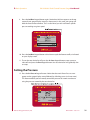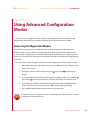
1
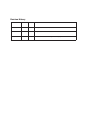
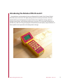
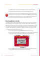
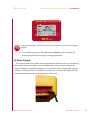
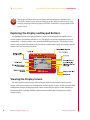
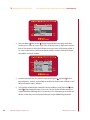
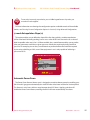
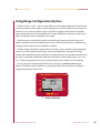
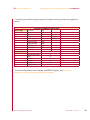
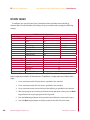
Retrotec Model DM-2A mark II
Dual Channel Pressure Gauge
User Guide
Revision History
Jan 29, 2008
0.00
Mark II, Jeff
Jan 29, 2008
0.01
Colin copied to Word 2003 and edited it.
Jan 31, 2008
0.02
Joe copied it to Word 2004 and edited it
0.03
Revised for documentation re-design and new style guide
Feb. 22, 2008
Steve
DM-2A Mark II Dual-Channel Pressure Gauge User Manual
Retrotec Model DM-2A mark II
Dual Channel Pressure Gauge
User Guide
Retrotec Energy Innovations, Ltd.
DM-2A Mark II 2008-02-22
DM-2A Mark II Dual-Channel Pressure Gauge User Manual
Copyright © 2005-2008 Retrotec Energy Innovations, Ltd. All rights reserved.
This document contains materials protected under International Copyright Laws. All rights reserved. No part of this
document may be copied or reproduced in any form or by any means without the prior written consent of Retrotec
Energy Innovations, Ltd.
Retrotec makes no warranties with respect to this documentation and disclaims any implied warranties of
merchantability, quality, or fitness for any particular purpose. The information in this document is subject to change
without notice. Retrotec reserves the right to make revisions to this publication without obligation to notify any person
or entity of any such changes.
ii
Retrotec Energy Innovations, Ltd.
DM-2A Mark II 2008-02-22
DM-2A Mark II Dual-Channel Pressure Gauge User Manual
About Retrotec Energy Innovations
Retrotec Energy Innovations, Ltd. manufactures blower doors (or door fans) that are used
in over 40 countries to measure the leakage rate of buildings, houses, rooms, ductwork and
enclosures. Retrotec’s Windows software uses the leakage results to calculate energy loss,
ventilation rates, smoke control and fire suppressant loss rates according to the following
standards:
Enclosure Integrity Tests using:
• NFPA 2001
• ISO 14520
Energy Loss Tests using:
• EN13829
• British CIBSE TM23
• Canadian CGSB 149.10
• American ASTM E779
• Europe CEN/TC
• Japanese standard
• Dutch NEN 2686
• SuperE
• Title 24
Smoke and Refuge using:
• PFEER
• 1994 Uniform Building Code Section 905
Enclosure integrity testing includes retention time calculations for all clean agent fire
suppressants such as FM-200, INERGEN, Argon, Argonite, FE-227, FE13, CO2, Nitrogen, NAF S III, and
Novec 1230. It also includes relief vent calculations and a test method for measuring relief vent
capacity in place.
Retrotec Energy Innovations, Ltd.
DM-2A Mark II 2008-02-22
iii
DM-2A Mark II Dual-Channel Pressure Gauge User Manual
Energy loss testing is used for measuring losses in large commercial buildings and residences
where mandatory testing is required to fulfill the criteria of certain jurisdictional standards. For
example, residential homes in Canada are tested to fulfill R-2000 requirements while existing
housing stock is tested for EnerGuide ratings using the CGSB standard. Canada has exported its
R-2000 technology abroad under the SuperE label where a special SuperE program performs the
needed test there.
Smoke control testing is performed under the 1994 Uniform Building Code Section 905 where
maximum leakage levels are specified. Retrotec door fans are capable of measuring the leakage
of an entire floor of almost any building, giving the designer useful quality control information to
calculate the transmission rate of smoke or pollutants from one floor to the next. Individual floors
can be isolated and measured so that the leakage area of each floor or component is known.
PFEER is the Protection for Fire and Emergency Evacuation Refuge intended for use on oil
platforms where a safe haven must be free of smoke and toxic fumes in the event of a mishap.
This is enforced by Lloyds of London shipping standards. Retrotec air current testers are used
as air movement detectors in a variety of applications but mostly to find leaks in the above
applications so the requirements of these standards can be met.
iv
Retrotec Energy Innovations, Ltd.
DM-2A Mark II 2008-02-22
DM-2A Mark II Dual-Channel Pressure Gauge User Manual
Table of Contents
Section 1
Getting Started
Installing the Batteries
Checking Battery Health
AC Power Adapter
Exploring the Display and Keypad Buttons
Viewing the Display Screen
Using the Keypad Buttons
3
3
4
5
6
6
7
Section 2
Working with the Setup Screen
Enabling and Disabling Devices
Enabling and Disabling Modes
@-mode Extrapolation Slope (n)
Automatic Power Down
Area Units
Volume Units
European Decimal Conventions
Sig Figs
Reverse Mode
13
13
15
17
17
18
18
19
20
20
Section 3
Connecting Your Gauge to a Fan
23
Section 4
Exploring Basic Test Operations
Setting the Mode
Using Time Average
Using Auto Zero
Setting the Fan Speed
Using Jog/Hold
Setting the Pressure
Retrotec Energy Innovations, Ltd.
27
27
28
28
29
30
31
DM-2A Mark II 2008-02-22
DM-2A Mark II Dual-Channel Pressure Gauge User Manual
Section 5
Using Advanced Configuration Modes
Accessing Configuration Modes
Preset Configuration
Choosing Custom Configuration Options
Using Range Configuration Options
33
33
34
34
35
Appendix A
Configuring and Using the DM-2A for Specific Standards
CGSB 149.10 Configuration
Canadian ecoENERGY Configuration
DS/EN 13829
37
37
38
40
Appendix B
Glossary of Terms and Abbreviations
Abbreviations
43
44
Appendix C
Getting Help With Your Gauge
Frequently Asked Questions
Getting Help
Main Offices
Contacting Technical Support
Submitting Gauges for Calibration and/or Repair
Warranty information
Period of Coverage
90-Day Warranty Exception
Repaired/Replacement Exception
Warranty on Refurbished Equipment
Who is Covered
Obtaining Warranty Service
Products Purchased from Resellers Products Purchased from Retrotec
Field Replacement/Repair
Factory Return and Repair
Immediate Exchange
Other Limitations
vi
Retrotec Energy Innovations, Ltd.
45
45
47
47
47
47
48
48
48
48
49
49
49
49
49
50
50
50
50
DM-2A Mark II 2008-02-22
Introducing the Retrotec DM-2A mark II
Congratulations on the purchase of your new Retrotec DM-2A mark II Dual-Channel Digital
Micromanometer and Control. This high-quality, precision measuring instrument is the most
advanced of its type and represents the state-of-the-art for air-tightness testing, enclosure
leakage measurement, and building performance assessment. This user guide will help you to
quickly set up and start using your gauge and will provide you with step-by-step instructions on
how to perform basic operations and configurations changes.
Retrotec Energy Innovations, Ltd.
DM-2A Mark II 2008-02-22
1: Getting Started
Retrotec Energy Innovations, Ltd.
DM-2A Mark II Dual-Channel Pressure Gauge User Manual
DM-2A Mark II 2008-02-22
1: Getting Started
DM-2A Mark II Dual-Channel Pressure Gauge User Manual
Section 1
Getting Started
Before you can begin using your new DM-2A mark II gauge, there are a few quick tasks you’ll
need to perform. You’ll find that setting up your gauge for first use and exploring its basic
operations is a relatively simple operation that takes just a few moments. In this section, you’ll
learn to install the batteries, determine battery health, and/or attach the power adapter.
Installing the Batteries
The DM-2A mark II requires four (4) rechargeable 1.5 volt NiMH (nickel metal hydride) AA type
batteries to operate. To install the rechargeable batteries, follow these steps:
1. Remove the panel labeled Battery Compartment on the under side of the gauge by
loosening the screw using a Phillips screw driver (as shown next) and removing the
battery compartment panel.
Do not open the panel labeled ‘No User Serviceable Parts Inside. Do Not Open.’ Doing so
will void your calibration and warranty.
Retrotec Energy Innovations, Ltd.
DM-2A Mark II 2008-02-22
1: Getting Started
DM-2A Mark II Dual-Channel Pressure Gauge User Manual
2. Install the batteries according to the orientation symbols on the circuit panel.
3. Replace the battery compartment panel and securely tighten the screw.
The DM-2A mark II contains a built-in NiMH battery charger. Other battery types (such as
alkaline batteries) can be used to power the DM-2A but you MUST remove these batteries
before attaching an external power source. Use only rechargeable NiMH AA batteries in
your DM-2A mark II gauge. Never attempt to recharge alkaline batteries.
Checking Battery Health
Your gauge features a battery health indicator that displays the current status of the battery
life while viewing the main operational screen. The battery health symbol is located at the
upper-left corner of the gauge display and indicates the battery’s remaining charge (as shown
next). Batteries are charged via an available external power source – such as the AC adapter or
an umbilical cable attached to a powered fan – regardless of whether the gauge is on or off.
To determine battery health, follow these steps:
1. Turn on the gauge by pressing the On/Off button once (as shown next).
2. The introduction screen will be displayed (shown next). After a short delay, the screen
will display the gauge model number, serial number, and calibration date.
3. Press the On/Off button a second time to view the main display screen. Locate the
battery health symbol at the upper-left corner (as shown next).
Retrotec Energy Innovations, Ltd.
DM-2A Mark II 2008-02-22
1: Getting Started
DM-2A Mark II Dual-Channel Pressure Gauge User Manual
Under typical operation, the DM-2A will operate for many hours on a set of fully charged
batteries.
4. To turn off the gauge, press and briefly hold the On/Off button. The display will
become blank indicating the gauge is no longer operational.
AC Power Adapter
Your gauge includes an AC adapter that will provide power when the unit is on and recharges
the batteries (if required) while it is attached. Without the AC power adapter attached, the
gauge will operate on available battery power. To attach the AC power adapter cable, plug the
pronged end of the unit into an available power outlet and insert the power adapter jack into
the port labeled Power on the top of the gauge (as shown next).
Retrotec Energy Innovations, Ltd.
DM-2A Mark II 2008-02-22
1: Getting Started
DM-2A Mark II Dual-Channel Pressure Gauge User Manual
Your gauge will charge while turned off and while external power is available either
from the AC adapter or from power available on the fan. While the batteries are actively
charging, the gauge will dimly display a ‘BATTERIES CHARGING’ message together with a
progress meter.
Exploring the Display and Keypad Buttons
Your Retrotec DM-2A mark II gauge features a touch-sensitive keypad that enables you to
use the gauge as an interface to the fan in use. The gauge is essentially comprised of two user
components—a display window and a set of specialized keypad buttons. The display window
(shown next) provides information on the current test mode and/or setup, and provides data on
device status and measurement values.
Viewing the Display Screen
The display portion of your gauge will provide you with all measurement values and the
current status of your device, test configuration, and test device as well as enable you to perform
configuration changes to the gauge itself. Labels surrounding the display screen indicate the
information that is statically available, while contextual information is displayed on various
display screens.
Retrotec Energy Innovations, Ltd.
DM-2A Mark II 2008-02-22
1: Getting Started
DM-2A Mark II Dual-Channel Pressure Gauge User Manual
The following list explains what each of the information labels printed around the perimeter
of your display screen represent:
• Baseline Indicates either the baseline pressure that will be deducted from the PrA
value or the current battery health status.
• n Indicates the value of the slope of the line along which @-measurements will be
extrapolated.
• Time Indicates time averaging on or off.
• Zero Indicates whether the auto zero feature is currently on or off.
• Speed Indicates the current speed signal going to the device as a percent value.
• Device Displays the device currently selected for use with your gauge.
• Range Config Indicates the current flow restrictor plate/ring/range configuration
set for the device.
• Set Indicates the pressure or fan speed that is being controlled.
• Pressure Indicates the pressure value for channel A.
• Mode Indicates the current results mode in use for the lower portion of the display.
• Volume and Area Input and Display Indicates the current value of the volume
used to calculate air changes or the area used in per-unit area displays.
• Jog/Hold display Indicates whether if the Jog or Hold features are currently active.
Using the Keypad Buttons
The keypad buttons (shown next) enable you to navigate screens, make selections, and
enter values in the course of your testing operations. The keypad buttons serve dual functions
according to the input expected and/or required by the device.
Retrotec Energy Innovations, Ltd.
DM-2A Mark II 2008-02-22
1: Getting Started
DM-2A Mark II Dual-Channel Pressure Gauge User Manual
The keys labeled 0 through 9 and the decimal point can be used for inputting values when
needed. You’ll also notice there are four directional keys labeled with arrows as in 2, 4, 6, and
8 representing up, left, right, and down (respectively). Besides the numeric and directional
functions, keys also include these secondary functions:
Mode ��������������������������������������������������������������������
The DM-2A mark II can display measurements and calculate results in
a variety of units. The upper portion of the display screen (PrA) always shows
channel A pressure, while the lower display area can change according to the
channel B display or the current mode. Press Mode continuously to cycle through
the selections made available from the Setup menu. Choose from these modes:
• Flow Displays the calculated flow though the fan.
• EqLA This displays the Equivalent Leakage Area, sometimes called the
Canadian ELA usually taken at 10 Pa .
• EfLA Displays the Effective Leakage Area (EfLA), sometimes called the US or
LBL (Lawrence Berkeley Labs) ELA and taken at 4 Pa.
• Air change Measures the air changes per hour. This mode requires that you
input the volume on the main screen.
• Flow/Area Displays the flow divided by the area that you have input on the
main screen.
• EqLA/Area Displays the equivalent leakage area (EqLA) divided by the area
that you have input on the main screen.
Retrotec Energy Innovations, Ltd.
DM-2A Mark II 2008-02-22
1: Getting Started
DM-2A Mark II Dual-Channel Pressure Gauge User Manual
• Velocity Displays the air velocity. This mode requires that a pitot tube be
installed.
• Velocity Flow Displays the flow calculated from the velocity and crosssectional area of the measured duct.
Range Config Press the Range Config keypad button to cycle through the
available flow ranges for the current test fan.
Setup Press the Setup keypad button to access the main Setup menu. The Setup
menu allows you to control and customize the gauge to meet your specific
testing needs. From the Setup menu you can choose to enable or disable devices
and/or modes, set the ‘n’ (@-mode extrapolation) value, set power down options,
and enter area and volume units and many other options (see Enabling and
Disabling Modes in Section 2, Working with the Setup Screen). Any changes you
make in the Setup menu are permanently saved.
Baseline The Baseline feature enables you to measure the background (baseline)
pressure in the room or enclosure before you begin testing. Once measured,
your gauge will automatically subtract this baseline pressure from your housepressure (PrA) measurements. Press the Baseline keypad button once to initiate
the baseline pressure reading test. Your gauge will display ‘Acquiring’ and will
begin to sample the background pressure. While acquiring the pressure values,
the gauge will continuously display the updated average pressure and the
duration of sampling on the screen. Pressing the button a second time to enable
the Baseline mode with the average pressure that was observed. From this point
on and until the feature is disabled, the baseline pressure displayed in the top left
corner of the screen will automatically be subtracted from the PrA readings. Press
the Exit keypad button to cancel out of Baseline mode.
Time Avg Press the Time Avg button to cycle through the available time
averaging settings or turn time averaging off. Time averaging causes the gauge
to display the average readings over the time interval. The current time averaging
value is displayed below the Time label on the gauge. Time averaging may be set
to 1, 2, 4, 8, 10, or 20 seconds, or 1 or 2 minutes.
Retrotec Energy Innovations, Ltd.
DM-2A Mark II 2008-02-22
1: Getting Started
DM-2A Mark II Dual-Channel Pressure Gauge User Manual
Auto Zero Press the Auto Zero keypad button to turn the automatic zeroing
function on or off. Automatic zeroing sets the gauge to automatically zero itself
every 10 seconds. Generally speaking, the DM-2 should be used with auto zero
feature on. However, to save batteries or when conducting high-speed computer
data acquisition you can maximize your gauge performance and data-transfer
rates by turning the Auto Zero feature on at the start of each data acquisition
cycle, but turn it off while the gauge is communicating with the computer.
Set Pressure The Set Pressure feature enables you to input any desired enclosure
pressure and place the gauge in Set Pressure mode. While in Set Pressure mode,
the gauge will automatically control the fan to achieve your desired enclosure
pressure.
For more information on using the Set Pressure feature, see Setting the Pressure in Section
4, Exploring Basic Test Operations.
Jog/Hold Pressing Jog/Hold cycles the gauge to Jog, Hold, or Off. Jog mode
is only available while the gauge is in Set Pressure or Set Speed modes. In Jog
mode, you can incrementally adjust the target fan speed one percent per click
or target enclosure pressure value 5 Pa per click using the (Up) and (Down)
keypad buttons. Hold mode freezes the current values being displayed.
While using Jog mode for Set Pressure, press and hold the (Up) and
buttons for three seconds to increase the target value by 5 Pa.
10
(Down) keypad
Set Speed This feature enables you to directly set the fan speed. While in Set
Speed mode, the gauge will automatically control the fan to achieve your desired
fan speed.
Device ��������������������������������������������������������������������������
Press this keypad button to enable you to cycle through the available fan
models. Devices can be enabled and disabled using the Setup menu.
@ Pressure If Set Speed is used, the first @ setting will be the displayed pressure.
If Set Pressure is used, the first @ setting will be the set pressure. The second @
setting will always be the value entered when the gauge is set up and can differ
for each mode.
Retrotec Energy Innovations, Ltd.
DM-2A Mark II 2008-02-22
1: Getting Started
DM-2A Mark II Dual-Channel Pressure Gauge User Manual
On / Off, Backlight Pressing this button once while the gauge is off turns it on
and displays the Retrotec introduction screen. Pressing the button a second time
displays the main operational display screen. While the gauge is on, you can press
this button to toggle the backlighting illumination for the display screen on or
off. Press and hold this button turn the gauge off.
Enter, Volume/Area This multi-application keypad button applies to several
functions. The Enter application is used to select menu items, cycle through
available options, or apply input values. The Volume and Area applications are
used to activate data entry for volume or area depending on the mode in use.
When these modes are activated, the display will display the current volume or
area being used and will flash “[ENTER]”.
Exit Press the Exit button to back out of the current menu screen and return to
the previous one, or to cancel a menu selection. Pressing the Exit keypad button
will also immediately shut down the fan and cancel out of Baseline, Set Pressure
and/or Set Speed modes.
Retrotec Energy Innovations, Ltd.
DM-2A Mark II 2008-02-22
11
1: Getting Started
DM-2A Mark II Dual-Channel Pressure Gauge User Manual
NOTES
12
Retrotec Energy Innovations, Ltd.
DM-2A Mark II 2008-02-22
2: Working with the Setup Screen
DM-2A Mark II Dual-Channel Pressure Gauge User Manual
Section 2
Working with the Setup Screen
If you’re preparing your DM-2A mark II gauge for first-time use, or need to make adjustments
to the gauge’s current setup configuration, this section will help guide you through the process
and briefly explain the available options. Follow the steps in this section to access the setup and
mode options. You’ll learn how to select device and mode setup options to enable or disable
testing devices, set the power-down feature, set unit measurement preferences for area and
volume measurements, choose European or North American decimal conventions, significant
figures, and reverse mode.
Enabling and Disabling Devices
In addition to Retrotec’s complete line of fan equipment, your DM-2A mark II supports fan
equipment from virtually every other fan manufacturer on the market. Chances are you have
only one or two different types of fan equipment. Rather than forcing you to tediously scroll
through all of the supported fan devices, the Device Setup sub-menu of the Setup menu enables
you to custom-configure your gauge to show only the specific fan devices that you use. The
final configuration is permanently saved in your gauge and can be changed at any time. Once
configured, the Device keypad button will cycle through only the devices that are currently
enabled.
To access the device setup options and enable or disable a device profile, follow these steps:
1. Press the On/Off button to turn on your gauge. Press On/Off a second time to exit
the introduction screen and view the main operational screen.
2. Press the Setup button to access the Setup menu.
3. Use the (Up) and
(as shown next).
Retrotec Energy Innovations, Ltd.
(Down) keypad buttons to navigate to Device Setup in the list
DM-2A Mark II 2008-02-22
13
2: Working with the Setup Screen
DM-2A Mark II Dual-Channel Pressure Gauge User Manual
4. Press the Enter, (Left), and/or (Right) keypad buttons to display the Enable/
Disable Device screen (as shown next). A list of device names is displayed in column
format. The column on the right indicates the current status of the device profile. A
Yes status in this column indicates the device profile is enabled, while No indicates
the profile is currently disabled.
5. Locate the fan device(s) you will be using by pressing the (Up) and (Down)
keypad buttons. Symbols surrounding the enabled or disable state will flash on and
off to indicate the state is selected.
6. To toggle the enable/disable state of the device profile on or off, press the (Left),
and/or (Right) keypad buttons. If you wish, you can disable all other devices to
simplify operation (although this isn’t necessary). This will enable you to disable fan
devices so that they are not displayed when pressing the Device keypad button.
14
Retrotec Energy Innovations, Ltd.
DM-2A Mark II 2008-02-22
2: Working with the Setup Screen
DM-2A Mark II Dual-Channel Pressure Gauge User Manual
7. Device ranges and/or configurations can also be custom-configured if needed. For
example, if you don’t require the low flow ranges for a Retrotec 2000 fan, you can
configure the gauge to disable the L4, L2, and L1 ranges. This will prevent those
ranges from being displayed when you press the Range Config keypad button. To
configure specific ranges, press Enter while the device is selected in the list to view
the available range options. Use the Enter, (Left), and/or (Right) keypad buttons
to cycle between Yes (enabled) or No (disabled) beside the device range in the list.
8. Once you have ensured that the device you want to use the gauge with is enabled
(and others are disabled, if desired), pressing the Exit keypad button to return to the
main Setup menu and again to return to the main operational screen.
Enabling and Disabling Modes
Your DM-2 mark II supports the calculation and display of a variety of house-testing and
building-science parameters. Some of these parameters will be useful for your specific testing
needs; others may be of little or no use to you. Rather than forcing you to tediously scroll though
all of the supported parameters, you can use Mode Setup to custom-configure your gauge to
enable access to only the specific parameters that are important to you. Configurations are
permanently saved in your gauge and can be changed at any time. Once configured, the Mode
keypad button will cycle through only those modes that are enabled in the Mode Setup menu.
To access mode setup options and change settings, follow these steps:
1. Press the On/Off button to turn on your gauge. Press On/Off a second time to exit
the Introduction screen and view the main operational screen.
2. Press the Setup button to access the Setup menu.
3. Using the (Up) and/or (Down) keypad buttons to navigate to Mode Setup in the
available list (as shown next).
Retrotec Energy Innovations, Ltd.
DM-2A Mark II 2008-02-22
15
2: Working with the Setup Screen
DM-2A Mark II Dual-Channel Pressure Gauge User Manual
4. Press the Enter, (Left), and/or (Right) keypad buttons to view the Enable/Disable
Modes screen. In this screen, you can enable or disable measurement modes select
the units of measurement for that mode. Available modes are: Pressure, Flow, EfLA,
EqLA, Air Changes, Flow per Area, EqLA per Area, Velocity and Velocity Flow.
Each mode has the following configuration options:
• Enable/Disable Setting the mode’s units to Off will disable that
parameter from being displayed when the Mode keypad button is
pressed during normal operation of the gauge. For example, to disable
EfLA from being displayed, set it to Off.
• Change Units All modes support a variety of units of measurement.
Selecting any unit of measurement will enable the parameter and will
display that parameter in the selected units.
• Define a Fixed-@-Pressure A unique fixed-@-pressure can be defined
for almost any parameter. For example, you can enable Flow@50Pa and
EfLA@4Pa to be displayed, simply by defining 50 and 4 as the @ pressures
for Flow and EfLA respectively.
5. Use the (Up) and/or (Down) keypad buttons to navigate the available menu
selections. Menu options differ depending on the mode you wish to change. For
example, some modes offer options while others require values to be entered.
6. Press the Enter, (Up) and/or (Down) keypad buttons to cycle through the
options available to select modes.
7. Press Enter to change value-based options. A value range will typically be displayed
to indicate the available values.
8. Enter your new value using the numeric keypad functions. Once you have entered
the correct value, press the Enter keypad button to apply the change. The new value
will be displayed beside the option.
9. Press the Enter keypad button to access the options for a selected menu item.
10. Once you applied and/or reviewed your new settings, press the Exit keypad
button to return to the main Setup menu and again to return to the main
operational screen.
16
Retrotec Energy Innovations, Ltd.
DM-2A Mark II 2008-02-22
2: Working with the Setup Screen
DM-2A Mark II Dual-Channel Pressure Gauge User Manual
To cancel an incorrectly entered value, press the Exit keypad button. Any values you
entered will not be applied.
For more information on selecting the configuration options available to each of the available
modes, see Choosing Custom Configuration Options in Section 5, Using Advanced Configurations.
@-mode Extrapolation Slope (n)
This option enables you to define the slope of the line along which @-mode extrapolations
will be calculated. Generally speaking, houses use a value of 0.65 and duct-work uses a value of
0.60. Acceptable values are 0.5 to 1.0. When enabled, the @-mode feature enables you to predict
what your parameter would be at a given pressure, without the need to physically reach that
pressure. For example, you can the @-mode feature to predict the flow that would be required
to pressurize a building to 50 Pa, even if the equipment in use is only capable of achieving a
pressure of 35 Pa.
Automatic Power Down
The Power Down feature (shown next) is designed to maximize battery power by enabling your
DM-2A mark II gauge to automatically turn itself off when it has been inactive for set time period.
This feature is set in hours within a range between 0 and 255 hours. Applying a 0 value will
disable the Power Down feature, meaning the DM-2 will never automatically shut down.
Retrotec Energy Innovations, Ltd.
DM-2A Mark II 2008-02-22
17
2: Working with the Setup Screen
DM-2A Mark II Dual-Channel Pressure Gauge User Manual
The Power Down feature affects normal operation during testing. Be certain to allow for
typical testing operations when choosing a setting.
Area Units
You can choose your unit measure preference for the area measurements that are displayed
on the gauge using the Area setup option (shown next). The area units may be set to square feet
(ft2), square meters (m2), square centimeters (cm2), or square inches (in2).
Volume Units
You can choose your Volume unit measure preference (as shown next) for the volume
measurements that are displayed on the gauge. The volume units may be set to cubic feet (ft2) or
cubic meters (m2).
18
Retrotec Energy Innovations, Ltd.
DM-2A Mark II 2008-02-22
2: Working with the Setup Screen
DM-2A Mark II Dual-Channel Pressure Gauge User Manual
European Decimal Conventions
Use the European decimal convention option to specify how whole and fractional values are
presented both on the display and in captured data. European conventions use a comma (,)
rather than a decimal point (.) to separate the integer portion of a number from the fractional
portion. Your DM-2A mark II gauge supports both conventions. Choosing Yes as the European
option (shown next) sets the decimal to a comma, while choosing No applies a period. For
example, ten and one half pascals would be displayed as 10,5.
Setting the European option to No will cause the gauge to display a period (decimal point)
as the separator between the integer and the fractional portion of the displayed number, as is
common in North America. For example, ten and one half pascals would be displayed as 10.5 Pa.
Retrotec Energy Innovations, Ltd.
DM-2A Mark II 2008-02-22
19
2: Working with the Setup Screen
DM-2A Mark II Dual-Channel Pressure Gauge User Manual
Sig Figs
The Significant Figures – or ‘Sig Figs’ – feature controls the number of significant digits displayed
and allows an extra digit, round to the nears 5 to be displayed. The available options are:
2.5 Two significant figures plus a third figure rounded to either 0 or 5.
3.0 Three significant figures.
3.5 Three significant figures plus a fourth figure rounded to either 0 or 5.
For example, the table shown next illustrates example values displayed using specific
significant figure options.
Base Number
1.0345
20.353
147.626
4326.72
2.5
1.05
20.0
150
4350
Significant Figures
3.0
1.03
20.4
148
4330
3.5
1.035
20.35
147.5
4325
Reverse Mode
The Reverse Mode option (shown next) essentially enables you to set your gauge to control a
fan device in reverse of normal operations. For normal operations, leave the Reverse Mode option
set to No, meaning the feature is disabled. This is the default configuration for your gauge.
20
Retrotec Energy Innovations, Ltd.
DM-2A Mark II 2008-02-22
2: Working with the Setup Screen
DM-2A Mark II Dual-Channel Pressure Gauge User Manual
In normal (forward) mode, your gauge will increase the fan speed in order to achieve higher
pressures and decrease the fan speed in order to achieve lower pressures. Reverse mode is used
for advanced neutralization testing and sets the gauge in Reverse Control mode. While in this
mode, the gauge will increase the fan speed in order to reduce the pressure and decrease the fan
speed in order to increase the pressure. Reverse Control mode is enabled by setting the Reverse
Mode option to Yes.
For more information on adjusting your gauge for specific measurement standards, see
Appendix A, Configuring and Using Your DM-2A Mark II Gauge for Specific Standards
discussed later in this user guide.
Retrotec Energy Innovations, Ltd.
DM-2A Mark II 2008-02-22
21
2: Working with the Setup Screen
DM-2A Mark II Dual-Channel Pressure Gauge User Manual
NOTES
22
Retrotec Energy Innovations, Ltd.
DM-2A Mark II 2008-02-22
3: Connecting Your Gauge
DM-2A Mark II Dual-Channel Pressure Gauge User Manual
Section 3
Connecting Your Gauge to a Fan
Connecting your DM-2A mark II to your Retrotec door fan or other similar device is a
straightforward operation. Your Retrotec umbilical cord includes the necessary tube and cable
connections. The tubes are color-coded to match other system hardware. For example, the red
pressure hose connects to the red pressure port on the top end of the gauge. The yellow pressure
tube connects to yellow pressure port, and so on. The pressure and hardware connection ports
are also clearly labeled on the top of your gauge as follows:
Pressure ports:
• Green Input B (+) • Yellow Ref B (-) (fan) • Red Ref A (-) (door) • Blue Input A (+) Hardware connections
• Speed Control Connects your gauge to a fan device using an Ethernet Retrotec
Control cable connection.
• USB PC The USB (Universal Serial Bus) port is used to connect the gauge to a PC
equipped with Retrotec software. Over this interface the computer can assume
complete control of the gauge for data acquisition and control for advanced
automated testing.
Use the LCD Contrast dial to increase or decrease the legibility of the display screen. Higher
contrast settings will increase the display screen legibility in low-light situations, but will
reduce battery life.
• Power Connects your gauge to an external power source using either the AC
power adapter or power available on the fan (if available).
Retrotec Energy Innovations, Ltd.
DM-2A Mark II 2008-02-22
23
3: Connecting Your Gauge
DM-2A Mark II Dual-Channel Pressure Gauge User Manual
Let’s explore a typical connection procedure as a practical example. To set up the connections
required to use a Retrotec fan device, follow these simple steps:
1. Plug the yellow Ethernet cable into the port labeled Speed Control.
2. Plug the red and yellow tubes into the color-coded pressure ports on the top side of
the gauge (as shown next). Ensure the tubes are snugly connected to the ports.
3. Locate the end of the umbilical cord that includes the longest length of red pressure
tube. Using the connections at this end of the umbilical cord, plug the yellow
Ethernet cable into the port labeled Speed Control on the fan top.
4. If external power is needed for the gauge, plug the power jack into the port labeled
Power on the top of the gauge. External power is provided either by the AC adapter
attached to an on-site AC power source, or (if available) power available from the fan.
To continue the set up operation and connect your gauge to the Retrotec door fan, follow
these steps:
5. Attach the Ethernet-style control cable to the port labeled Speed Control on the top
panel of the fan.
6. Attach the yellow flow-pressure tube to the yellow port labeled Ref B (fan) on the top
panel of the fan.
7. Attach the power cord jack (if available) to the port labeled Power on the top panel of
the fan.
8. Plug the main AC power cord for the fan into an available power supply source and
attach the opposite end to the port on the fan top panel labeled Main Power.
24
Retrotec Energy Innovations, Ltd.
DM-2A Mark II 2008-02-22
3: Connecting Your Gauge
DM-2A Mark II Dual-Channel Pressure Gauge User Manual
9. Pass the red pressure tube through the door panel or cloth to the other side of
the door. This tube is intentionally 15 feet longer than the yellow pressure tube to
accommodate the extra distance required and is designed to measure the pressure
created across the wall. Pull all of the red tubing to the other side of the door and
lay it in a location that is beyond the flow stream of the fan and not subject to wind
effects.
10. Your Retrotec DM-2A mark II gauge and door fan are now connected and ready for
you to perform basic test operations.
Retrotec Energy Innovations, Ltd.
DM-2A Mark II 2008-02-22
25
3: Connecting Your Gauge
DM-2A Mark II Dual-Channel Pressure Gauge User Manual
NOTES
26
Retrotec Energy Innovations, Ltd.
DM-2A Mark II 2008-02-22
4: Basic Operations
DM-2A Mark II Dual-Channel Pressure Gauge User Manual
Section 4
Exploring Basic Test Operations
Now that your DM-2A mark II gauge and fan are properly connected you’re ready to begin
taking measurements. A good place to start is to conduct a simple pressure-pressure test. Doing
this, you’ll learn how to turn on the gauge, choose a Mode, activate Time Average and Auto Zero
features, and control fan speed and pressure using Set Speed, Set Pressure, and Jog/Hold.
Follow these steps as a practical example:
1. With your DM-2A mark II gauge and testing device properly connected, turn on
your gauge by pressing the On/Off keypad button once to display the Retrotec
introduction screen and press any keypad button to proceed to the main operational
screen.
The procedure involved in each of the following steps applies to a typically configured
gauge. If your gauge has been configured differently, the specific information discussed in
these steps may differ from your current setup.
Setting the Mode
2. Press the Mode keypad button to cycle through the enabled modes until the display
screen indicates two pressure readings—PrA and PrB (as shown next). Notice the
pressure readings on the gauge fluctuate slightly. This is due to minute pressure
changes in the room or enclosure that the gauge is currently measuring. Since the
DM-2A mark II takes pressure readings 20 times per second, the readings can change
rapidly.
Retrotec Energy Innovations, Ltd.
DM-2A Mark II 2008-02-22
27
4: Basic Operations
DM-2A Mark II Dual-Channel Pressure Gauge User Manual
Using Time Average
3. The time averaging feature calculates the average pressure over a given time period.
Pressing the Time Avg keypad button enables you to cycle through the range of
time-averaging intervals: Off, 1s, 2s, 4s, 8s, 10s, 20s, 1m, and 2m (where s represents
seconds and m represents minutes). The current time average interval is displayed in
the display window below the Time label (as shown next). Press the Time Avg keypad
button once and notice that the pressure values change according to the current
time average setting.
Using Auto Zero
4. Press the Auto Zero keypad button once to activate the feature. Your gauge will
periodically produce an audible clicking sound. When Auto Zero is active,
your gauge’s solenoids will automatically be reset every ten seconds. Your gauge
display indicates the Auto Zero On or Off state below the Zero label in the upper-right
corner of the screen (as shown next). Press the Auto Zero keypad button to turn off
the feature.
28
Retrotec Energy Innovations, Ltd.
DM-2A Mark II 2008-02-22
4: Basic Operations
DM-2A Mark II Dual-Channel Pressure Gauge User Manual
Using the Auto Zero feature consumes additional power that may be a consideration when
operating your gauge on batteries alone.
Setting the Fan Speed
5. Press the Set Speed keypad button. Notice the Fan Speed %: prompt appears on the
gauge display screen followed by a blinking cursor (as shown next). This feature
enables you to directly enter the fan speed to a value between 1 and 100 percent. For
example, enter a value of 25 and press the Enter keypad button to apply the value.
The fan speed on the test device will gradually increase to the percentage value you
entered.
Depending on what your current Time Average feature is set to while using the Set Speed
feature, it may take longer for the readings on the gauge to update to the actual value.
Retrotec Energy Innovations, Ltd.
DM-2A Mark II 2008-02-22
29
4: Basic Operations
DM-2A Mark II Dual-Channel Pressure Gauge User Manual
6. While the Set Speed feature is active, the current speed of the fan will be displayed
in the lower-right corner of the display screen (as shown next). The pressure
values displayed will remain relatively constant, although minute changes are to
be expected.
Using Jog/Hold
7. Press the Jog/Hold keypad button once. Notice that Jog now appears at the top
centre of your gauge display screen (as shown next).
8. Press the (Up) and/or (Down) keypad buttons to adjust the speed of the test
device fan. Each keypad button press will change the test device fan speed by 1
percent.
Press and hold the (Up) and/or
speed by five percent increments.
30
Retrotec Energy Innovations, Ltd.
(Down) keypad buttons to change the test device fan
DM-2A Mark II 2008-02-22
4: Basic Operations
DM-2A Mark II Dual-Channel Pressure Gauge User Manual
9. Press the Jog/Hold keypad button again. Notice that Hold now appears at the top
centre of your gauge display screen (as shown next). In this state, your gauge will
hold the current measurements. This is useful when you wish to freeze a specific
pressure reading at a given speed.
10. Press the Jog/Hold keypad button a third time to cycle the feature to off, as indicated
on your display screen.
11. To turn the test device fan off, press the Set Speed keypad button, enter a percent
value of 0 and press the Enter keypad button. Your test device fan will gradually slow
to a stop.
Setting the Pressure
12. Press the Set Pressure keypad button. Notice that the words Room Pressure: now
appear on the gauge display screen followed by a blinking cursor (as shown next).
This feature enables you to manually control the pressure of a room or enclosure
using the pressure created by the test device fan.
Retrotec Energy Innovations, Ltd.
DM-2A Mark II 2008-02-22
31
4: Basic Operations
DM-2A Mark II Dual-Channel Pressure Gauge User Manual
The Set Pressure feature will cannot be used in free-air tests.
13. For example, enter a value of 25 and press the Enter keypad button. The fan speed on
the test device will gradually increase until the pressure value you entered is matched
by the value displayed next to the PrA reading (as shown next).
14. Press and hold the On/Off keypad button to end your test session. The test fan will
gradually slow to a stop.
The larger the enclosure, the more time may be required for the fan to match the pressure
requested using the Set Pressure feature.
By following this practical exploration of the basic operation of your gauge, you’ve learned how
to turn on your gauge, conduct basic speed and pressure tests, take readings, and view the status
of certain gauge features. Once you’ve familiarized yourself with these basic operations, you can
begin to use the gauge to accomplish more complex measurements.
32
Retrotec Energy Innovations, Ltd.
DM-2A Mark II 2008-02-22
5: Advanced Modes
DM-2A Mark II Dual-Channel Pressure Gauge User Manual
Section 5
Using Advanced Configuration
Modes
The DM-2A mark II gauge has several different pre-programmed test measurement mode
configurations that enable you to quickly calculate various measurements in the field.
Accessing Configuration Modes
By default, your gauge comes configured with a number of commonly used modes preenabled. However, if you need to you can change the enabled modes or their displayed units
at any time. For example, to meet a specific requirement or preference you can display pressure
values in PSF instead of Pa. These types of configuration changes are simple and straightforward
to perform.
To quickly access and/or change measurement mode configurations, follow these brief steps:
1. Press the Setup button, select Mode Setup, and press Enter to view the Enable/Disable
Modes menu screen.
2. Navigate to select a mode in the list using the
buttons.
(Up) and/or
(Down) keypad
3. To cycle through the unit measurement types for available modes press the Enter,
(Up) and/or (Down) keypad buttons. Choosing Off disables the selected mode.
4. To change pressure values associated with specific modes press the Enter keypad
button, enter the pressure value, and press Enter again to apply the change.
5. Press the Exit keypad button twice to return to the main menu.
For detailed steps on setting device modes, see Enabling and Disabling Devices in Section
2, Working with the Setup Screen.
Retrotec Energy Innovations, Ltd.
DM-2A Mark II 2008-02-22
33
5: Advanced Modes
DM-2A Mark II Dual-Channel Pressure Gauge User Manual
Preset Configuration
By default, your DM-2A mark II gauge is set to use a preset unit measurement configuration
for each of the available modes. These defaults affect how all measurements are displayed. The
default unit measurement configurations are listed in the following table:
Mode
Settings
Pressure
Flow
EfLA
EqLA
Air Changes
Flow per Area
EqLA per Area
Velocity
Velocity Flow
Pa
cfm
Off
ft2
/h
Off
Off
Off
Off
@ 50 Pa
@ 4 Pa
@ 10 Pa
@ 50 Pa
Choosing Custom Configuration Options
You can customize your mode configurations and unit measurements independently as
needed. The changes you apply to the unit measurements will affect the information displayed
by your gauge during your test operations. The custom unit measurement configurations
available for you to choose from are listed in the table shown next.
Mode
Pressure
Flow
EfLA
EqLA
Air Change
Flow per Area
EqLA per Area
Velocity
Velocity Flow
34
Retrotec Energy Innovations, Ltd.
Pa
Off
Off
Off
Off
Off
Off
Off
Off
in wc
cfm
cm2
cm2
/h
3
m /hr/m2
ft2/ft2
m/s
cfm
Options
PSF
l/s
in2
in2
m3/s
ft2
ft2
cfm/ft2
in2/100ft2
km/h
l/s
l/s/m2
in2/ft2
f/s
m3/s
m3/h
cm2/m2
fpm
m3/h
DM-2A Mark II 2008-02-22
5: Advanced Modes
DM-2A Mark II Dual-Channel Pressure Gauge User Manual
Using Range Configuration Options
Each flow device – or fan – supports various flow restrictor range configurations which enable
you to test enclosures with larger or smaller leakage areas. Each fan model that your gauge can
control can use a unique set of flow ranges. Your DM-2A gauge can be configured to specific
range configuration for your selected device. The range configuration setting you select in turn
affects all calculated values displayed by your gauge.
The flow ranges are achieved by enlarging or reducing the opening of the fan being used
delivers air flow to the enclosure being tested. Using a combination of various-sized fitted rings
and plugs the fan opening can be enlarged or reduced.
The flow settings achieved by applying these restrictions apply a specific range configuration
value and as the fan opening size changes, the range configuration is changed. The range
configurations applied to the fan correspond to configurations on your gauge for the device you
are using. For example, the Retrotec 3300 series door-fan has 7 flow ranges (Open, A, B, C8, C4,
C2, C1) which correspond to the rings and plugs while they are installed in the fan opening.
You can change the range configuration for your gauge using the Range Config keypad
button. The current range is indicated on your gauge’s display screen adjacent to the Range
Configuration label (as shown next).
Retrotec Energy Innovations, Ltd.
DM-2A Mark II 2008-02-22
35
5: Advanced Modes
DM-2A Mark II Dual-Channel Pressure Gauge User Manual
NOTES
36
Retrotec Energy Innovations, Ltd.
DM-2A Mark II 2008-02-22
A: Specific Configurations
DM-2A Mark II Dual-Channel Pressure Gauge User Manual
Appendix A
Configuring and Using the DM2A for Specific Standards
Different unit measurement conventions are often used and/or required in different
jurisdictions and vary according to the standards set out by local codes and authorities. You
can configure your DM-2A mark II gauge to adhere to virtually any code or standard in a
few moments using the procedures described previously in this user guide. See Accessing
Configuration Modes in Section 5 Using Advanced Configuration Modes.
The following section details the recommended configurations you will need to set your DM2A mark II gauge to in order to obtain measurements based on specific standards.
CGSB 149.10 Configuration
To configure your DM-2A mark II gauge to display measurements and adhere to the Canadian
General Standards Board (CGSB) 149.10, choose the following options:
Mode Setup
(Other Settings)
Retrotec Energy Innovations, Ltd.
CGSB 149.10 Configuration
Pressure
Flow
EfLA
EqLA
Air Changes
Flow per Area
EqLA per Area
Velocity
Velocity Flow
n
Power Down Hour
Area
Volume
European
Sig Figs
Reverse Mode
Pa
l/s
Off
cm2
/h
Off
cm2/m2
Off
Off
@ 25Pa
@ 10Pa
@ 50Pa
@ 10Pa
.65
2
m2
m3
No
2.5
No
DM-2A Mark II 2008-02-22
37
A: Specific Configurations
DM-2A Mark II Dual-Channel Pressure Gauge User Manual
To perform your CGSB 149.10 standards test procedure, follow these steps:
1. Assess and measure the Envelope Area as specified in the standard.
2. With your gauge on and running and from the main operation screen, press the
Mode keypad button to set your gauge to EqLA/Area mode.
For the EqLA/Area mode to be available, it must be enabled. To enable a mode use options
in the Setup screen. A mode is enabled when it is set to a value other than off.
3. Press the Enter keypad button and input the envelope area value according to
your measurements.
4. Conduct door-fan test at 50 Pa or as specified in the standard.
5. Use the @ Pressure keypad button to display the Flow @ 25.0 Pa and the EqLA @
10.0 Pa.
6. Results for EqLA and NLA (=EqLA/Area) may be read directly from your gauge.
7. Your CGSB 149.10 standards test procedure is complete.
For more information on standards used by the Canadian General Standards Board, visit
http://pwgsc.gc.ca/cgsb/home/index-e.html.
Canadian ecoENERGY Configuration
The Canadian ecoENERGY Program requires reading of EqLA at 10 Pa and air-changes at 50 Pa.
Most test technicians prefer using imperial units but metric units are simply to apply. Your DM2A gauge will provide these values automatically without doing a multipoint test or you can
use Retrotec’s Door-Fan 3.0 software to perform the test manually or even automatically with
Retrotec model Q systems such as the Q46, Q4E and Q56.
38
Retrotec Energy Innovations, Ltd.
DM-2A Mark II 2008-02-22
A: Specific Configurations
DM-2A Mark II Dual-Channel Pressure Gauge User Manual
To configure your DM-2A mark II gauge for the Canadian ecoEnergy requirements, apply these
settings:
Mode Setup
(Other Settings)
Canadian ecoENERGY Configuration
Pressure
Pa
Flow
off
EfLA
Off
EqLA
In2
@ 10.0 Pa
Air Changes
/h
@ 50.0 Pa
Flow per Area
Off
EqLA per Area
Off
Velocity
Off
Velocity Flow
Off
n
Power Down Hour
Area
Volume
European
Sig Figs
Reverse Mode
0.65
2
m2
m3
No
2.5
No
For more information on the Canadian ecoENERGY Program, visit http://www.
ecoaction.gc.ca/ecoenergy-ecoenergie/index-eng.cfm
Retrotec Energy Innovations, Ltd.
DM-2A Mark II 2008-02-22
39
A: Specific Configurations
DM-2A Mark II Dual-Channel Pressure Gauge User Manual
DS/EN 13829
To configure your gauge for the Dansk Standard for thermal performance of buildings,
determination of air permeability of buildings, fan pressurization method, apply the following
settings:
Mode Setup
(Other Settings)
DS/EN 13829 Configuration
Pressure
Pa
Flow
m3/h
EfLA
Off
EqLA
Off
Air Changes
/h
Flow per Area
cm3/h/m2
EqLA per Area
Off
Velocity
Off
Velocity Flow
Off
n
Power Down Hour
Area
Volume
European
Sig Figs
Reverse Mode
@ 50.0 Pa
@ 50.0 Pa
@ 50.0 Pa
0.65
2
m2
m3
No
2.5
No
DS/EN 13829 is a multi-point test. However, the DM-2A mark II can also provide for
quick single-point checks of the enclosure. To perform a single-point test, follow these
steps:
1. Assess and measure the Envelope Area as specified in the standard.
2. Assess and measure the Net Floor Area as specified in the standard.
3. Assess and measure the Internal Volume of the building as specified in the standard.
4. With your gauge on and running and from the main operation screen, press the Mode
keypad button to set your gauge to the Air Chg mode.
5. Press the Enter keypad button and input the Internal Volume as measured in step 3.
6. Press the Mode keypad button to display screen to view the Flow/Area mode.
40
Retrotec Energy Innovations, Ltd.
DM-2A Mark II 2008-02-22
A: Specific Configurations
DM-2A Mark II Dual-Channel Pressure Gauge User Manual
7. Press the Enter keypad button and input either the Envelope Area or the Net Floor
Area as follows:
• The Envelope Area if you wish to display Air Permeability as specified in the
standard.
• The Net Floor Area is you wish to display Specific Leakage Rate as specified in
the standard.
8. Press the @ Pressure button to display the Flow @ 50.0 Pa, Air Changes @ 50.0 Pa, and
either Air Permeability or Specific Leakage Rate @ 50.0 Pa.
9. Results may be read directly from the DM-2A mark II.
10. In order to record both Air Permeability and Specific Leakage Rate, you will
need to re-enter the Envelope Area and Net Floor Area values according to your
measurements and/or calculations.
Retrotec Energy Innovations, Ltd.
DM-2A Mark II 2008-02-22
41
A: Specific Configurations
DM-2A Mark II Dual-Channel Pressure Gauge User Manual
NOTES
42
Retrotec Energy Innovations, Ltd.
DM-2A Mark II 2008-02-22
B: Glossary
DM-2A Mark II Dual-Channel Pressure Gauge User Manual
Appendix B
Glossary of Terms and
Abbreviations
As you learn how to use your gauge and/or consult sections within this guide, you may
encounter abbreviations that you’re unfamiliar with.
• ACH Air changes per hour.
• EfLA Effective leakage area being measured.
• EqLA Equivalent leakage area being measured.
• EqLA/Area EqLA divided by the area that you have input into the Setup menu.
• Flow Calculated flow though the fan.
• Flow/Area Flow divided by the area that you have input into the setup menu.
• Velocity Flow Flow calculated from the velocity and cross-sectional area.
• Velocity Air velocity (requires installation of a pitot tube).
• Door Fan A test instrument that fits into an open doorway in order to pressurize
and enclosure. The result is a measurement of the opening size.
• Envelope The surfaces composed of floor and walls and floors that separate the
test volume from volume surrounding the test volume.
• Equivalent Leakage Area (ELA or EqLA) This is the total size of all opens in an
enclosure. The EqLA value is also referred to as the whole room leakage and includes
leaks through the ceiling and below the ceiling area (BCLA). In CA2001 this is
measured in units of square feet or square meters at a reference pressure in Pascals.
The ELA should not be confused with another EqLA that is often called the EfLA or
Effective Leakage Area. It is very unfortunate that both these ELA’s have the same
acronym of ELA. The EfLA was developed for the US ASTM standard and is smaller
than the EqLA by at least a factor of 0.61 because it uses a discharge coefficient of 1.0.
This EfLA is sometimes referred to as the LBL or Lawrence Berkley Labs EqLA because
it was developed and used by LBL natural air change model that enjoys wide usage.
Retrotec Energy Innovations, Ltd.
DM-2A Mark II 2008-02-22
43
B: Glossary
DM-2A Mark II Dual-Channel Pressure Gauge User Manual
• Flow Pressure The pressure difference between inside the fan (in the flow stream)
and ambient air, outside the fan.
• Room Pressure The pressure difference between inside the building/room under
test and the ambient outside air.
• Pascal (Pa) Often abbreviated to Pa, this represents a very small metric unit of
pressure. There are 249 Pascals in 1 water column. A water column is the pressure
required to push water up 1 inch in a tube. One Pascal = 0.000145 pounds per square
inch.
Abbreviations
• /h Per hour
• cfm Cubic feet per minute
• cm2 Square centimeters
• fpm Feet per minute
• fps Feet per second
• ft2 Square feet
• in wc Inches of water column
• in2 Square inches
• km/h Kilometers per hour
• l/s Liters per second
• m/s Meters per second
• m2 Square meters
• m3/h Cubic meters per hour
• m3/s Cubic meters per second
• mph Miles per hour
• Pa Pascals
• PSF Pounds per square foot
• Sig Fig Significant figures
• l/s/m2 Liters per second per square meter
• NLA Normalized leakage area
44
Retrotec Energy Innovations, Ltd.
DM-2A Mark II 2008-02-22
C: Getting Help
DM-2A Mark II Dual-Channel Pressure Gauge User Manual
Appendix C
Getting Help With Your Gauge
As you become familiar with using your DM-2A mark II gauge, you may have questions with
its basic operations and/or functions or you may encounter a situation that seems out of the
ordinary. There is often a simple answer or solution to solving common problems.
Frequently Asked Questions
Before contacting Retrotec technical support, review the answers to these frequently asked
questions geared toward solving common difficulties:
Q: Nothing appears on the display screen when I turn on my gauge. Is my gauge
damaged?
A: Your Retrotec gauge is designed for maximum durability in the most rigorous usage
scenarios. If nothing appears on the display screen after pressing the On/Off keypad
button, check for the following:
• If running on battery power only, check that the batteries are installed (and
installed correctly).
• Turn the LCD Contrast button on the top side of the gauge to increase the
display screen contrast.
• Plug the AC power adapter jack into a power outlet and insert it into the port
marked Power on the top side of the gauge and press the On/Off keypad
button again.
Q: The test device I wish to use does not appear when I cycle through the device list by
pressing the Device keypad button. How do I select my test device?
A: The device you wish to use may be disabled in the Setup options. To enable a device,
follow these brief steps:
1. With your gauge on and running and from the main operational screen, press
the Setup keypad button.
2. Navigate the Setup menu selections and select Device Setup in the menu.
Retrotec Energy Innovations, Ltd.
DM-2A Mark II 2008-02-22
45
C: Getting Help
DM-2A Mark II Dual-Channel Pressure Gauge User Manual
3. Press the Enter keypad button to display the Enable/Disable Device screen
showing a list of device profile names. A Yes status in the right-hand column
indicates the device profile is enabled; a No indicates the profile is currently
disabled.
4. Select your device and toggle its enable/disable state using the
(Right) keypad buttons.
(Left), and/or
5. Press the Exit keypad button to return to the main Setup menu and again to
return to the main operational screen.
6. For more information on enabling or disabling test devices, see Choosing Mode
Setup Options in Section 2 Working with the Setup Screen.
46
Q: The room pressure value my gauge is displaying doesn’t appear to be correct? What’s
causing this?
A: This is often caused by the Baseline mode inadvertently being left on. Check the
status information next to the Baseline label on the display. To toggle the Baseline
status off, press the Baseline keypad button once.
Q: The pressure values on my gauge display intermittently and the gauge itself seems
to be operating sluggishly. Is it malfunctioning?
A: It may be that the Time Average feature is active and set to a long time interval.
Check the status information next to the Time label on the display. To turn the Time
Average status off or decrease the interval time period, press the Time Avg keypad
button to cycle through the available options.
Q: I have tried to resolve my problem on my own, but I believe my gauge is
malfunctioning. What do I do?
A: If you are unable to resolve your current problem on your own, contact technical
support using the contact information in the following section.
Retrotec Energy Innovations, Ltd.
DM-2A Mark II 2008-02-22
C: Getting Help
DM-2A Mark II Dual-Channel Pressure Gauge User Manual
Getting Help
If you are unable to resolve a problem you’ve encountered or you suspect there may be a more
complex problem with your gauge, contact Retrotec using one of the options discussed in the
following section.
Main Offices
Retrotec Energy Innovations Ltd.
611-1540 West 2nd Avenue
Vancouver, BC V6J 1H2 Canada
Web Site: www.retrotec.com
Contacting Technical Support
Tel: 604-732-0142
Fax: 604-737-0162
Email: [email protected]
Hours of Operation
Pacific Standard Time: 0800-1700
Eastern Standard Time: 1100-2000
Greenwich Mean Time: 1600-0100
Submitting Gauges for Calibration and/or Repair
All systems requiring calibration or repair must be shipped to our manufacturing facility for
calibration and repair work. Please include a detailed packing list. If possible, take digital photos
of your equipment prior to shipping.
Retrotec Inc.
1060 East Pole Road
Everson, WA USA 98247
IMPORTANT: Do not send air current testers with any equipment submitted for repair. If these items are
sent to the repair center, they will not be returned.
Retrotec Energy Innovations, Ltd.
DM-2A Mark II 2008-02-22
47
C: Getting Help
DM-2A Mark II Dual-Channel Pressure Gauge User Manual
Warranty information
Your limited warranty covers defects in materials and workmanship in “Products” manufactured by Retrotec to the extent
of repair or replacement except in the case of air current testers where replacement is the only option provided all
shipping costs are paid by the first end user.
Your limited warranty does not cover the following items:
•
Products that have been subjected to:
•
Misuse, neglect or accident
•
Physical damage during shipping
•
Improper installation, operation, application or handling
•
Water or fire or dust or chemical damage
•
Products that have been damaged due to repair, alteration, or modification unless specifically requested by
Retrotec.
•
Damage due to normal wear and tear.
•
Parts and components manufactured by third parties and packaged with Retrotec Products such as printers
and computers. Warranty of these items is covered under the original manufacturer’s warranty. Locate the
nearest original manufacturer service center for problems related to these components.
•
Costs (including any duties or applicable fees) of shipping your warranted Products to Retrotec for repair.
•
Lost business due to malfunctions
Period of Coverage
Subject to the following exemptions, the limited warranty period is for 24 months from when the Products were
purchased by the first end-user:
90-Day Warranty Exception
The limited warranty is for 90 days for the following parts:
•
Weather-strip
•
Cloth for Aluminum-Frame Doors, Carry-cases and Covers
•
Air Current Testers
•
Flex-duct
Repaired/Replacement Exception
The limited warranty is for the balance of the original warranty or for 90 days from the date returned and delivered to the
first end-user, whichever is longer.
48
Retrotec Energy Innovations, Ltd.
DM-2A Mark II 2008-02-22
C: Getting Help
DM-2A Mark II Dual-Channel Pressure Gauge User Manual
Warranty on Refurbished Equipment
The limited warranty is for 180 days on all refurbished equipment.
Who is Covered
This limited warranty extends to the first end-user purchaser who bought Products directly from Retrotec. If Retrotec
Products were purchased through a Retrotec Authorized Reseller, that Reseller may be able to offer better service.
Retrotec may always be contacted directly for warranty service.
Obtaining Warranty Service
Products Purchased from Resellers
If you have bought directly from a Retrotec Reseller, call the company you bought it from and describe your problem.
They may be able to respond more quickly and save you shipping costs. Your reseller will decide whether:
•
To send field replacement parts, or
•
To authorize you to return the Product to the Reseller for service, or
•
To send an immediate exchange, or
•
To instruct you to contact Retrotec directly
Products Purchased from Retrotec
If your Products were purchased directly from Retrotec, phone (604)732-0142 or send an email to [email protected]
and describe the problem. Proof of date of purchase will be required. Retrotec will decide whether:
•
To send field replacement parts, or
•
To send an immediate exchange, or
•
To authorize you too return the Product to Retrotec for service
If Retrotec has authorized a return, address the shipment to:
Retrotec Inc
1060 East Pole Road
Everson, WA, USA, 98247
Attention: Warranty, Repair, & Calibration
All returns must have freight, duty and brokerage prepaid and must include a note stating:
•
The problem
•
The contact person at your company
•
Phone number
•
A return address
Retrotec Energy Innovations, Ltd.
DM-2A Mark II 2008-02-22
49
C: Getting Help
DM-2A Mark II Dual-Channel Pressure Gauge User Manual
Field Replacement/Repair
Most defective parts are easily field-replaceable. This is the fastest way to get problems corrected and repairs completed.
If Retrotec agrees that Warranty Replacement Parts are required, Retrotec will ship the necessary parts to you free of
charge, and at Retrotec’s expense, using the carrier and method of our choice. Rush or Express shipments will be at your
expense.
Factory Return and Repair
All Products covered by this warranty, with the exception of air-current testers, may be returned to Retrotec for repair
and service at your expense for shipping, duty and brokerage. Returned products found to be covered under this limited
warranty will be repaired or replaced, free of charge, and returned to you at Retrotec’s expense, using the carrier and
method of our choice. Rush or Express shipments will be at your expense. Products found to be not covered under this
limited warranty will be repaired and returned to you at your expense, upon receipt of full payment for such repairs and
shipping. Products found not to be defective will be shipped back at your expense.
Immediate Exchange
Retrotec offers to send out Immediate Exchange replacement Products with the following conditions:
•
The problem occurs within the first 14 days of receipt
•
The product was purchased direct from Retrotec.
•
Retrotec will provide a quotation for these Products including your choice of shipping. Upon full
payment of this quotation, Retrotec will ship these Immediate Exchange Products.
•
Defective Products must be returned to Retrotec. Upon their return, our service personnel will assess all
Defective Products.
•
If Products are found to be defective, then costs for all Products and shipping by standard delivery (non
rush), will be credited back your account.
Other Limitations
This is Retrotec’s complete warranty for the Products, and states your exclusive remedies. This limited warranty is
given in lieu of all other express warranties. Implied warranties, including without limitation, the implied warranties of
merchantability and fitness for a particular purpose, are given only if specifically required by applicable law. Otherwise,
they are specifically excluded.
No warranty is made that the software will meet your requirements or will work in combination with any hardware
or applications software products provided by third parties or that any/all defects in the software products will be
corrected.
In no event shall Retrotec be liable, whether in contract or tort (including negligence) for damages in excess of the
purchase price of the Product, or for any indirect, incidental, special or consequential damages of any kind, or loss of
revenue or profits, loss of business, loss of information or data, or other financial loss arising out of or in connection with
the ability or inability to use the Products, to the full extent these damages may be disclaimed by law.
50
Retrotec Energy Innovations, Ltd.
DM-2A Mark II 2008-02-22